CN217656402U - A multi-span large-span top mobile power supply aerial facility system - Google Patents
A multi-span large-span top mobile power supply aerial facility systemDownload PDFInfo
- Publication number
- CN217656402U CN217656402UCN202221755426.4UCN202221755426UCN217656402UCN 217656402 UCN217656402 UCN 217656402UCN 202221755426 UCN202221755426 UCN 202221755426UCN 217656402 UCN217656402 UCN 217656402U
- Authority
- CN
- China
- Prior art keywords
- cable
- wire rope
- assembly
- pulley
- lifting
- Prior art date
- Legal status (The legal status is an assumption and is not a legal conclusion. Google has not performed a legal analysis and makes no representation as to the accuracy of the status listed.)
- Expired - Fee Related
Links
Images


Classifications
- Y—GENERAL TAGGING OF NEW TECHNOLOGICAL DEVELOPMENTS; GENERAL TAGGING OF CROSS-SECTIONAL TECHNOLOGIES SPANNING OVER SEVERAL SECTIONS OF THE IPC; TECHNICAL SUBJECTS COVERED BY FORMER USPC CROSS-REFERENCE ART COLLECTIONS [XRACs] AND DIGESTS
- Y02—TECHNOLOGIES OR APPLICATIONS FOR MITIGATION OR ADAPTATION AGAINST CLIMATE CHANGE
- Y02T—CLIMATE CHANGE MITIGATION TECHNOLOGIES RELATED TO TRANSPORTATION
- Y02T10/00—Road transport of goods or passengers
- Y02T10/60—Other road transportation technologies with climate change mitigation effect
- Y02T10/70—Energy storage systems for electromobility, e.g. batteries
Landscapes
- Carriers, Traveling Bodies, And Overhead Traveling Cranes (AREA)
Abstract
Translated fromChinese
Description
Translated fromChinese技术领域technical field
本实用新型涉及移动供电空中设施技术领域,尤其涉及一种多索式大跨距顶部移动供电的空中设施系统。The utility model relates to the technical field of mobile power supply air facilities, in particular to a multi-cable type large-span top mobile power supply air facility system.
背景技术Background technique
随着杂戏演出、空中表演形式的多样性发展,演出剧目的日新月异,为了演员的安全,设备的可靠,目前的高空表演装置的驱动系统多采用临时的,只适用于本场合的演出,而且只是吊挂轻巧的道具,钢索端部不可调节,钢索顶部滑轮偏角大;道具在旋转过程中存在主索受力不均,吊点剧烈摆动,钢索容易缠绕;钢索顶部移动供电,供电系统运动与道具运动不协调,电缆在钢索上运行容易出现卡滞现象,从而影响供电效果;同时目前大部分驱动设备只有一套减速电机,一旦减速电机故障,会导致演出中断或者终止。With the diversified development of various forms of performances and aerial performances, the repertoire of performances is changing with each passing day. For the safety of actors and the reliability of equipment, the driving systems of current high-altitude performance devices are mostly temporary, which are only suitable for performances on this occasion. It is only for hanging light props, the end of the wire rope cannot be adjusted, and the pulley on the top of the wire rope has a large declination angle; during the rotation of the props, the main cable is not uniformly stressed, the hanging point swings violently, and the wire rope is easily entangled; the top of the wire rope moves to supply power , the movement of the power supply system is not coordinated with the movement of the props, and the cable is prone to jam when running on the steel cable, which affects the power supply effect; at the same time, most of the current driving equipment only has a set of geared motors. Once the geared motor fails, the performance will be interrupted or terminated. .
实用新型内容Utility model content
本实用新型的目的在于提供一种多索式大跨距顶部移动供电的空中设施系统,从而解决现有技术中存在的前述问题。The purpose of the present utility model is to provide a multi-cable type large-span top mobile power supply aerial facility system, so as to solve the aforementioned problems existing in the prior art.
为了实现上述目的,本实用新型采用的技术方案如下:In order to achieve the above purpose, the technical scheme adopted by the present utility model is as follows:
一种多索式大跨距顶部移动供电的空中设施系统,包括钢立柱组件、辅助支撑组件、承载及供电钢索、钢索固定组件、旋转导向滑轮组件、运行小车、吊具组件、升降钢丝绳、行走钢丝绳、循环钢丝绳、电缆拖轮组、电缆拖轮头、驱动组件、电缆驱动装置;A multi-cable large-span top mobile power supply aerial facility system, including steel column components, auxiliary support components, bearing and power supply steel cables, steel cable fixing components, rotating guide pulley components, running trolleys, spreader components, lifting wire ropes , walking wire rope, circulating wire rope, cable tug set, cable tug head, drive assembly, cable drive device;
表演场地顶部相对两侧的钢结构上分别设置有一个钢立柱组件,承载及供电钢索的两端分别绕过钢立柱组件顶部设置的钢索支撑滑轮组件后经钢索固定组件与所述钢结构固定连接;A steel column assembly is respectively set on the steel structure on the opposite sides of the top of the performance venue. Structure fixed connection;
所述电缆拖轮组、电缆拖轮头和运行小车依次间隔悬挂在所述承载及供电钢索上,所述电缆拖轮组与所述电缆拖轮头相连,所述电缆拖轮头与所述运行小车相连,运行小车下方设置有吊具组件;The cable tug set, the cable tug head and the running trolley are suspended on the bearing and power supply steel cables in sequence, the cable tug set is connected with the cable tug head, and the cable tug head is connected with the running trolley, A spreader assembly is arranged under the running trolley;
所述钢立柱组件的侧面设置有与其固定连接的辅助支撑组件,所述辅助支撑组件的顶部设置有钢丝绳支撑滑轮组件,所述钢立柱组件的下端以及其附近的钢结构上设置有旋转导向滑轮组件,所述吊具组件和运行小车上连接有升降钢丝绳,所述升降钢丝绳的两端绕过相应侧的旋转导向滑轮组件后分别与驱动组件和钢立柱组件上的旋转吊环固定连接;所述运行小车上固定连接有行走钢丝绳,所述行走钢丝绳的两端分别绕过相应侧的钢丝绳支撑滑轮组件后与所述驱动组件相连;The side of the steel column assembly is provided with an auxiliary support assembly that is fixedly connected to it, the top of the auxiliary support assembly is provided with a wire rope support pulley assembly, and the lower end of the steel column assembly and the steel structure near it are provided with a rotating guide pulley group. A lifting wire rope is connected to the spreader assembly and the running trolley, and the two ends of the lifting wire rope bypass the rotating guide pulley assembly on the corresponding side and are respectively fixedly connected to the rotating lifting ring on the driving assembly and the steel column assembly; The running trolley is fixedly connected with a walking wire rope, and the two ends of the walking wire rope respectively bypass the wire rope supporting pulley assembly on the corresponding side and are connected with the driving assembly;
所述循环钢丝绳的一端与所述电缆驱动装置相连,所述循环钢丝绳的另一端依次绕过所述电缆拖轮组和所述电缆拖轮头后与所述电缆驱动装置相连;所述电缆和/或光纤搭设在所述电缆拖轮组和所述电缆拖轮头上。One end of the circulating wire rope is connected to the cable driving device, and the other end of the circulating wire rope is connected to the cable driving device after bypassing the cable tug set and the cable tug head in turn; the cable and/or Optical fibers are mounted on the cable tug set and the cable tug head.
优选的,所述承载及供电钢索包括平行且间隔设置的承载钢索和电缆钢索,所述电缆钢索的两侧分别设置有至少一条承载钢索,所述运行小车悬挂在所述承载钢索和所述电缆钢索上,所述电缆拖轮组和所述电缆拖轮头悬挂在所述电缆钢索上;所述承载钢索和电缆钢索的型号通过离散仿真技术进行计算选择,所述承载钢索和电缆钢索上连接有实时拉力检测装置,所述实时拉力检测装置实时检测承载钢索和电缆钢索的拉力,当拉力超过预设拉力的120%,即发出警报,实现过载保护。Preferably, the bearing and power supply cables include parallel and spaced bearing cables and cable cables, at least one bearing cable is respectively provided on both sides of the cable cables, and the running trolley is suspended on the bearing cables. On the wire rope and the cable wire rope, the cable tug set and the cable tug head are suspended on the cable wire rope; The load-bearing wire rope and the cable wire rope are connected with a real-time tension detection device. The real-time tension detection device detects the tension of the load-bearing wire rope and the cable wire rope in real time. When the tension exceeds 120% of the preset tension, an alarm is issued to realize overload. Protect.
优选的,所述吊具组件包括升降连接座、设置在所述升降连接座下表面的吊具以及设置在所述升降连接座两端的旋转升降滑轮;所述运行小车包括行走连接座、设置在行走连接座上的钢丝绳固定座、设置在所述行走连接座顶部的行走滑轮和行走导向轮以及设置在所述行走连接座两端的升降导向轮和旋转导向轮;升降钢丝绳的一端与驱动组件相连,另一端先依次绕过钢立柱组件上的旋转导向滑轮组件、运行小车一侧的升降导向轮和吊具组件上的旋转升降滑轮后,再依次绕过运行小车另一侧的升降导向轮后与钢立柱组件上的旋转吊环固定连接;行走钢丝绳与钢丝绳固定座固定连接,所述行走钢丝绳的两端分别绕过运行小车上相应端的旋转导向轮后,再绕过钢立柱组件上的旋转导向滑轮组件和钢丝绳支撑滑轮组件以及钢立柱组件一侧设置的配重导轨上的张紧轮后,与驱动组件相连;所述承载钢索绕过所述行走滑轮,所述电缆钢索绕过所述行走导向轮,所述行走钢丝绳与所述行走连接座固定连接。Preferably, the sling assembly includes a lifting connecting seat, a sling disposed on the lower surface of the lifting connecting seat, and rotating lifting pulleys arranged at both ends of the lifting connecting seat; the running trolley includes a walking connecting seat, which is arranged on the The wire rope fixing seat on the walking connection seat, the walking pulley and the walking guide wheel arranged on the top of the walking connection seat, and the lifting guide wheel and the rotating guide wheel arranged at both ends of the walking connection seat; one end of the lifting wire rope is connected with the drive assembly , the other end first bypasses the rotating guide pulley assembly on the steel column assembly, the lifting guide wheel on one side of the running trolley and the rotating lifting pulley on the spreader assembly, and then bypasses the lifting guide wheel on the other side of the running trolley. It is fixedly connected with the rotating ring on the steel column assembly; the walking wire rope is fixedly connected with the wire rope fixing seat, and the two ends of the walking wire rope respectively bypass the rotating guide wheel on the corresponding end of the running trolley, and then bypass the rotating guide on the steel column assembly. The pulley assembly and the wire rope support pulley assembly and the tensioning wheel on the counterweight guide rail set on one side of the steel column assembly are connected to the drive assembly; the carrying wire rope goes around the walking pulley, and the cable wire rope goes around the The walking guide wheel is used, and the walking wire rope is fixedly connected with the walking connecting seat.
优选的,所述驱动组件包括升降装置和行走装置,空中设施系统包括四条行走钢丝绳和四条升降钢丝绳,四条升降钢丝绳分别连接一套升降装置,即一条升降钢丝绳由一套升降装置驱动,四条行走钢丝绳与同一套行走装置相连,即四条行走钢丝绳由一套行走装置驱动;行走装置与升降装置都采用卷扬机驱动的方式实现运动。Preferably, the drive assembly includes a lifting device and a traveling device, and the aerial facility system includes four traveling wire ropes and four lifting wire ropes, and the four lifting wire ropes are respectively connected to a set of lifting devices, that is, one lifting wire rope is driven by a set of lifting devices, and the four walking wire ropes are driven by a set of lifting devices. It is connected with the same set of walking devices, that is, the four walking wire ropes are driven by a set of walking devices; both the walking device and the lifting device are driven by a hoist to achieve movement.
优选的,所述行走装置和所述升降动装置均包括固定底座、自排绳组件、卷筒组件、卷筒固定组件、链轮、驱动链条和电机组件;所述固定底座的上表面设置有沿其长度方向延伸的导轨,所述导轨上设置有能够沿其移动的移动支架;所述卷筒固定组件水平设置在固定底座的上方,且其两端与移动支架固定连接,所述卷筒组件同轴设置在所述卷筒固定组件的内部;所述卷筒固定组件上设置有两个电机组件,两个电机组件分别与卷筒组件的两端相连;所述自排绳组件包括丝杠和螺母,所述丝杠的一端与所述固定底座相连,所述螺母套设在所述丝杠上,所述螺母与所述卷筒固定件固定连接且游动设置,所述丝杠和所述卷筒组件的一端分别设置有一个链轮,所述驱动链条与两个链轮啮合;Preferably, both the walking device and the lifting and lowering device include a fixed base, a self-arranging rope assembly, a drum assembly, a drum fixing assembly, a sprocket, a drive chain and a motor assembly; the upper surface of the fixed base is provided with A guide rail extending along its length direction, the guide rail is provided with a movable bracket that can move along the guide rail; the reel fixing assembly is horizontally arranged above the fixed base, and its two ends are fixedly connected with the movable bracket, the reel The assembly is coaxially arranged inside the drum fixing assembly; two motor assemblies are arranged on the drum fixing assembly, and the two motor assemblies are respectively connected with both ends of the drum assembly; the self-arranging rope assembly includes a wire A screw and a nut, one end of the screw is connected to the fixed base, the nut is sleeved on the screw, the nut is fixedly connected to the drum fixing piece and is set in a floating manner, the screw is and one end of the reel assembly is respectively provided with a sprocket, and the drive chain is engaged with the two sprockets;
所述卷筒组件包括旋转轴、轴套、挡绳辊和卷筒;所述卷筒的两端设置有旋转轴,所述旋转轴通过键连接有轴套,所述轴套经轴承与行走卷筒固定组件相连;所述卷筒的两端设置有挡绳辊;The reel assembly includes a rotating shaft, a shaft sleeve, a rope blocking roller and a reel; the two ends of the reel are provided with a rotating shaft, the rotating shaft is connected with a shaft sleeve through a key, and the shaft sleeve is connected to the running through a bearing. The reel fixing components are connected; both ends of the reel are provided with rope blocking rollers;
各所述升降钢丝绳分别缠绕在各相应升降装置的卷筒上,各所述行走钢丝绳的两端分别一收一放间隔缠绕在所述行走装置的卷筒上。Each of the lifting wire ropes is respectively wound on the reel of each corresponding lifting device, and both ends of each of the traveling wire ropes are respectively wound on the reel of the walking device at intervals.
优选的,所述升降钢丝绳在升降装置的卷筒上缠绕的节距与所述升降装置的丝杠的节距分别通过卷筒上的链轮齿数和丝杠上的链轮齿数进行调整,最终两者相等;所述行走钢丝绳在行走装置的卷筒上缠绕的节距与所述行走装置的丝杠的节距分别通过卷筒上的链轮齿数和丝杠上的链轮齿数进行调整,最终两者相等。Preferably, the winding pitch of the lifting wire rope on the drum of the lifting device and the pitch of the lead screw of the lifting device are respectively adjusted by the number of sprocket teeth on the drum and the number of sprocket teeth on the lead screw, and finally The two are equal; the pitch of the walking wire rope wound on the drum of the traveling device and the pitch of the screw of the traveling device are adjusted by the number of sprocket teeth on the drum and the number of sprocket teeth on the screw, respectively. In the end both are equal.
优选的,所述电缆拖轮组包括多个间隔悬挂在所述电缆钢索上的电缆拖轮,相邻两个电缆拖轮之间经链条连接,位于端部的一个电缆拖轮经链条与所述电缆拖轮头相连;所述电缆拖轮头经链条与所述运行小车相连。Preferably, the cable tug set includes a plurality of cable tugs suspended on the cable steel wire at intervals, two adjacent cable tugs are connected by a chain, and one cable tug at the end is connected to the cable tug via a chain The head of the cable tug is connected with the running trolley through a chain.
优选的,所述电缆拖轮包括第一支架、挡片、第一滑轮组、第二滑轮组、第二支架和电缆支撑;所述第一支架一侧的两端分别设置有一第一滑轮组,所述第一支架的另一侧的两端分别连接有一个挡片,所述挡片的相对两侧分别设置有一第二滑轮组,所述挡片上设置有链条连接件;所述第一支架中部连接有垂直于其的第二支架,所述第二支架与电缆支撑相连,所述第二支架上设置有压板,所述电缆和/或光纤伸展在所述电缆支撑上且经压板压紧;所述链条连接件与与其相邻的电缆拖轮上的链条连接件经链条相连;第一滑轮组与电缆钢索相连,循环钢丝绳从电缆驱动装置伸出绕过钢结构上的旋转导向滑轮组件后,再绕过一侧的两个第二滑轮组后经电缆拖轮头转向绕过另一侧的两个第二滑轮组,最后再绕过钢结构上的旋转导向滑轮组件后固定在电缆驱动装置上。Preferably, the cable tug includes a first bracket, a baffle, a first pulley group, a second pulley group, a second bracket and a cable support; two ends of one side of the first bracket are respectively provided with a first pulley group, the first pulley group Two ends of the other side of a bracket are respectively connected with a blocking piece, the opposite sides of the blocking piece are respectively provided with a second pulley group, the blocking piece is provided with a chain connecting piece; the middle part of the first bracket is connected with a vertical the second bracket, the second bracket is connected with the cable support, the second bracket is provided with a pressure plate, the cable and/or the optical fiber is stretched on the cable support and pressed by the pressure plate; the chain The connecting piece is connected with the chain connecting piece on the adjacent cable tug through the chain; the first pulley group is connected with the cable wire rope, and the circulating wire rope extends from the cable drive device and goes around the rotating guide pulley assembly on the steel structure, and then goes around. The two second pulley groups on one side are turned around the two second pulley groups on the other side through the cable tug head, and finally they are fixed on the cable drive device after they bypass the rotating guide pulley assembly on the steel structure.
优选的,电缆拖轮头包括第一支架、第一挡片、第一滑轮组、转向滑轮、第二支架和电缆支撑;所述第一支架一侧的两端分别设置有一第一滑轮组,所述第一支架的另一侧的两端分别连接有一个挡片,所述挡片上设置有链条连接件,其中一个挡片的相对两侧分别设置有一第二滑轮组,另一挡片上设置有转向滑轮;所述第一支架中部连接有垂直于其的第二支架,所述第二支架与电缆支撑相连,所述第二支架上设置有压板,所述电缆和/或光纤伸展在所述电缆支撑上且经压板压紧;第一滑轮组与电缆钢索相连,循环钢丝绳绕过一侧的第二滑轮组后经转向滑轮转向后绕过另一侧的一个第二滑轮组。Preferably, the cable tug head includes a first bracket, a first baffle, a first pulley group, a steering pulley, a second bracket and a cable support; two ends of one side of the first bracket are respectively provided with a first pulley group, the first pulley group Two ends of the other side of a bracket are respectively connected with a blocking piece, a chain connecting piece is arranged on the blocking piece, a second pulley group is respectively provided on the opposite sides of one blocking piece, and a diverting pulley is provided on the other blocking piece; The middle part of the first bracket is connected with a second bracket perpendicular to it, the second bracket is connected with the cable support, the second bracket is provided with a pressure plate, and the cable and/or the optical fiber is stretched on the cable support The first pulley set is connected with the cable wire rope, and the circulating wire rope bypasses the second pulley set on one side and then turns around by the steering pulley and then bypasses a second pulley set on the other side.
优选的,所述第一滑轮组包括上下相邻设置的悬挂滑轮,所述电缆钢索穿过两个悬挂滑轮之间的缝隙;所述第二滑轮组包括上下相邻设置的大滑轮和小滑轮,所述链条连接件位于所述小滑轮的下方;所述循环钢丝绳穿过大滑轮和小滑轮之间的缝隙;所述第一滑轮组与第二滑轮组通过旋转轴自动调节角度,令电缆拖轮头和电缆拖轮组能够在带有坡度的钢索上平稳运行。Preferably, the first pulley group includes suspension pulleys arranged up and down adjacently, and the cable wire passes through the gap between the two suspension pulleys; the second pulley group includes a large pulley and a small pulley arranged adjacently up and down, The chain connector is located under the small pulley; the circulating wire rope passes through the gap between the large pulley and the small pulley; the first pulley group and the second pulley group automatically adjust the angle through the rotating shaft, so that the cable tug head and the The cable tug set can run smoothly on steel cables with slopes.
本实用新型的有益效果是:1、通过升降以及行走工作的双电机自排绳结构,实现速度快、行程大的道具与场景切换功能,合理布置运行小车的数量、升降行走吊点,实现一车或多车在承载及供电钢索上自动调节角度并平稳顺畅运行。2、运行小车上各吊点处的滑轮摆动设置,使其能够承载道具旋转的复杂动作,运行小车的水平运行由一套行走装置驱动,升降钢丝绳和行走钢丝绳两两备份,实现机械冗余设计,机械设计同步运行。3、在运行小车移动时,电缆拖轮随运行小车进行移动,固定在电缆拖轮上的电缆及光纤随着电缆拖轮移动,电缆及光纤留有足够的余量,保证线电缆及光纤与运行小车的协调运行,实现大跨度钢索上长距离强弱电、光缆信号的传输效果。4、通过采用双电机结构,增加设备的可靠性,主减速电机出现故障,可迅速切换到备用减速电机,实现“零误差”运行。5、系统的运行速度快、自动化程度高、工作效率高,满足了剧场的功能使用。The beneficial effects of the utility model are as follows: 1. Through the double-motor self-arranging rope structure for lifting and walking, realizing the switching function of props and scenes with fast speed and large stroke, rationally arranging the number of running trolleys, lifting and walking lifting points, and realizing a The car or multi-car automatically adjusts the angle on the carrying and power supply cables and runs smoothly and smoothly. 2. The swing setting of pulleys at each lifting point on the running trolley enables it to carry the complex motion of prop rotation. The horizontal running of the running trolley is driven by a set of walking devices, and the lifting wire rope and the walking wire rope are backed up by two to realize the mechanical redundancy design. , the mechanical design runs synchronously. 3. When the running trolley moves, the cable tug moves with the running trolley, the cables and optical fibers fixed on the cable tug move with the cable tug, and there is enough margin for the cables and optical fibers to ensure that the cables and optical fibers are in line with the running trolley. Coordinated operation to achieve long-distance strong and weak current and optical cable signal transmission effects on long-span steel cables. 4. By adopting the double motor structure, the reliability of the equipment is increased. If the main deceleration motor fails, it can be quickly switched to the backup deceleration motor to achieve "zero error" operation. 5. The system has fast running speed, high degree of automation and high work efficiency, which satisfies the functional use of the theater.
附图说明Description of drawings
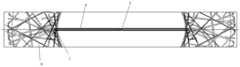
图1是实用新型实施例中空中设施系统的结构示意图;1 is a schematic structural diagram of an aerial facility system in an embodiment of the utility model;
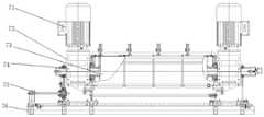
图2是实用新型实施例中空中设施系统的俯视图;Fig. 2 is the top view of the aerial facility system in the utility model embodiment;
图3是实用新型实施例中运行小车、电缆拖轮和电缆拖轮头的示意图;Fig. 3 is the schematic diagram of running trolley, cable tug and cable tug head in the embodiment of the utility model;
图4是实用新型实施例中运行小车与吊具组件的连接示意图;4 is a schematic diagram of the connection between the running trolley and the spreader assembly in the embodiment of the utility model;
图5是实用新型实施例中升降装置的结构示意图;5 is a schematic structural diagram of a lifting device in an embodiment of the utility model;
图6是实用新型实施例中行走装置的结构示意图;Fig. 6 is the structural representation of the walking device in the embodiment of the utility model;
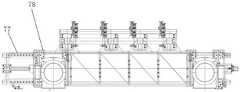
图7是实用新型实施例中电缆拖轮组的结构示意图;Fig. 7 is the structural representation of the cable tug set in the embodiment of the utility model;
图8是实用新型实施例中电缆拖轮的结构示意图;8 is a schematic structural diagram of a cable tug in an embodiment of the utility model;
图9是实用新型实施例中电缆拖轮头的结构示意图。9 is a schematic structural diagram of a cable tug head in an embodiment of the utility model.
图中:1、鸟巢;2、电缆拖轮;21、第一支架;22、挡片;23、悬挂滑轮;24、大滑轮;25、小滑轮;26、第二支架;27、电缆支撑;28、压板;3、电缆拖轮头;31、转向滑轮;32、链条;33、链条连接件;4、承载及供电钢索;41、承载钢索;42、电缆钢索;5、运行小车;51、行走连接座;52、行走滑轮;53、升降导向轮;54、行走导向轮;6、吊具组件;61、升降连接座;62、旋转升降滑轮;7、升降装置;71、电机;72、卷筒固定组件;73、卷筒组件;74、链轮;75、丝杠;76、固定底座;77、导轨;78、移动支架;8、钢结构;9、钢立柱组件;10、钢索固定组件;11、旋转导向滑轮组件;12、升降钢丝绳;13、行走钢丝绳;14、循环钢丝绳;15、电缆和/或光纤;16、行走装置。In the figure: 1. Bird's nest; 2. Cable tug; 21. First bracket; 22. Block; 23. Suspension pulley; 24. Large pulley; 25. Small pulley; 26. Second bracket; 27. Cable support; 28 , pressure plate; 3, cable tug head; 31, steering pulley; 32, chain; 33, chain connector; 4, bearing and power supply cable; 41, bearing cable; 42, cable cable; 5, running trolley; 51 , walking connection seat; 52, walking pulley; 53, lifting guide wheel; 54, walking guide wheel; 6, spreader assembly; 61, lifting connecting seat; 62, rotating lifting pulley; 7, lifting device; 71, motor; 72 73, reel assembly; 74, sprocket; 75, lead screw; 76, fixed base; 77, guide rail; 78, mobile bracket; 8, steel structure; 9, steel column assembly; 10,
具体实施方式Detailed ways
为了使本实用新型的目的、技术方案及优点更加清楚明白,以下结合附图,对本实用新型进行进一步详细说明。应当理解,此处所描述的具体实施方式仅仅用以解释本实用新型,并不用于限定本实用新型。In order to make the purpose, technical solutions and advantages of the present utility model more clearly understood, the present utility model will be further described in detail below with reference to the accompanying drawings. It should be understood that the specific embodiments described herein are only used to explain the present invention, and are not used to limit the present invention.
如图1和图2所示,本实施例中,提供了一种多索式大跨距顶部移动供电的空中设施系统,包括钢立柱组件9、辅助支撑组件、承载及供电钢索4、钢索固定组件10、旋转导向滑轮组件11、运行小车5、吊具组件6、升降钢丝绳12、行走钢丝绳13、循环钢丝绳14、电缆拖轮组、电缆拖轮头3、驱动组件、电缆驱动装置;As shown in Figures 1 and 2, in this embodiment, a multi-cable long-span top mobile power supply aerial facility system is provided, including a
表演场地顶部相对两侧的钢结构8上分别设置有一个钢立柱组件9,承载及供电钢索4的两端分别绕过钢立柱组件9顶部设置的钢索支撑滑轮组件后经钢索固定组件10与所述钢结构8固定连接;A
所述电缆拖轮组、电缆拖轮头3和运行小车5依次间隔悬挂在所述承载及供电钢索4上,所述电缆拖轮组与所述电缆拖轮头3相连,所述电缆拖轮头3与所述运行小车5相连,运行小车5下方设置有吊具组件6;The cable tug set, the
所述钢立柱组件9的侧面设置有与其固定连接的辅助支撑组件,所述辅助支撑组件的顶部设置有钢丝绳支撑滑轮组件,所述钢立柱组件9的下端以及其附近的钢结构8上设置有旋转导向滑轮组件11,所述吊具组件6和运行小车5上连接有升降钢丝绳12,所述升降钢丝绳12的两端分别绕过相应侧的旋转导向滑轮组件11后与驱动组件和钢立柱组件9上的旋转吊环固定连接;所述运行小车5上固定连接有行走钢丝绳13,所述行走钢丝绳13的两端分别绕过相应侧的支撑滑轮组件后与所述驱动组件相连;The side of the
所述循环钢丝绳14的一端与所述电缆驱动装置相连,所述循环钢丝绳14的另一端依次绕过所述电缆拖轮组和所述电缆拖轮头3后与所述电缆驱动装置相连;所述电缆和/或光纤15搭设在所述电缆拖轮组和所述电缆拖轮头3上。One end of the circulating
本实施例中,假设表演场地为鸟巢1;则钢立柱组件9安装在鸟巢1顶部相对两侧的钢结构8上;承载钢索41的两端分别经钢立柱组件9支撑后通过钢索固定组件10固定在鸟巢1相对两侧的钢结构8上,令承载钢索41悬挂在鸟巢1上空。In this embodiment, it is assumed that the performance venue is the bird's nest 1; the
本实施例中,所述钢索固定组件10包括钢索固定头、钢索拉锚和实时拉力监测装置,所述钢索固定头通过销轴固定连接在钢索拉锚上,所述钢索拉锚与所述钢结构8固定连接;所述实时拉力监测装置与所述承载钢索41和电缆钢索42相连。In this embodiment, the wire
钢索支撑滑轮组件固定在支撑立柱上,钢索支撑滑轮组件受力大并在低温环境使用,因此选材时采用耐低温的材料,同时钢索支撑滑轮组件设置钢索挡绳辊及钢索防跳槽装置,防止运行小车5在承载及供电钢索4上运行时出现承载及供电钢索4跳槽至钢索支撑滑轮组件外侧和钢索支撑滑轮组件与钢索支撑滑轮座侧隙中;承载及供电钢索4的端部经钢索固定组件10固定,钢索固定组件10通过销轴连接固定在钢索拉锚上,钢索拉锚固定在鸟巢1的钢结构8上。由于鸟巢1的结构以及温度、风量、雨雪、吊挂道具载荷的影响,承载钢索41和电缆钢索42的挠度会发生变化,承载钢索41和电缆钢索42的受力会发生变化,通过实时监测拉力装置,可实时监测承载及供电钢索4的拉力,当拉力超过设计的120%,就会报警,实现过载保护,确保设备安全可靠。The wire rope support pulley assembly is fixed on the support column. The wire rope support pulley assembly is subject to large force and is used in a low temperature environment. Therefore, materials that are resistant to low temperature are used when selecting materials. The jumping device prevents the load and power supply wire 4 from jumping to the outside of the wire rope support pulley assembly and the side gap between the wire rope support pulley assembly and the wire rope support pulley seat when the running
系统中各部件之间都适当留有合适的间距,各运行小车5在带有斜坡的承载钢索41上不会出现钢丝绳的缠绕,相邻的运行小车5也不会出现碰撞。Appropriate distances are properly reserved between the components in the system, so that each running
如图3至图7所示,本实施例中,所述承载及供电钢索4包括平行且间隔设置的承载钢索41和电缆钢索42,所述电缆钢索42的两侧分别设置有至少一条承载钢索41,所述运行小车5悬挂在所述承载钢索41和所述电缆钢索42上,所述电缆拖轮组和所述电缆拖轮头3悬挂在所述电缆钢索42上。承载钢索41和电缆钢索42的型号根据实际情况通过离散型仿真技术进行选取,并且通过对运行小车的结构设计进行多工况分析,解决超静定的多索支撑技术。承载钢索41的设置数量也可以根据实际情况进行选择。As shown in FIG. 3 to FIG. 7 , in this embodiment, the bearing and power supply cables 4 include parallel and spaced
所述吊具组件6包括升降连接座61、设置在所述升降连接座61下表面的吊具以及设置在所述升降连接座61两端的旋转升降滑轮62;所述运行小车5包括行走连接座51、设置在行走连接座51上的钢丝绳固定座、设置在所述行走连接座51顶部的行走滑轮52和行走导向轮54以及设置在所述行走连接座51两端的升降导向轮53和旋转导向轮;升降钢丝绳12的一端与驱动组件相连,另一端先依次绕过钢立柱组件9上的旋转导向滑轮组件11、运行小车5一侧的升降导向轮53和吊具组件6上的旋转升降滑轮62后,再依次绕过运行小车5另一侧的升降导向轮53后与钢立柱组件9上的旋转吊环固定连接;行走钢丝绳13与钢丝绳固定座固定连接,所述行走钢丝绳13的两端分别绕过运行小车5上相应端的旋转导向轮后,再绕过钢立柱组件9上的旋转导向滑轮组件11和钢丝绳支撑滑轮组件以及钢立柱组件9一侧设置的配重导轨上的张紧轮后,与驱动组件相连;所述承载钢索41绕过所述行走滑轮52,所述电缆钢索42绕过所述行走导向轮54,所述行走钢丝绳13与所述行走连接座51固定连接。The
本实施例中,承载钢索41的数量为四条,电缆钢索42的数量为一条;电缆钢索42位于中间,两侧分别设置两条承载钢索41。运行小车5的行走连接座51采用矩形结构,在运行小车5行走连接座51的四角分别设置一组行走滑轮52和一组升降导向轮53,移动方向相对两侧的中部分别设置一组行走导向轮54。相应侧的承载钢索41绕过相应侧的行走滑轮52,电缆钢索42绕过行走导向轮54后,将运行小车5悬挂在承载钢索41上。In this embodiment, the number of bearing
同样的为了保证吊具组件6的平稳升降,吊具组件6的升降连接座61也设置为矩形的,升降连接座61的四角分别设置一组旋转升降滑轮62;系统中包括多条分别位于运行小车5的相对两侧的升降钢丝绳12,相应侧的升降钢丝绳12一端与驱动组件相连,另一端依次绕过行走连接座51一角的升降导向轮53、升降连接座61一角上的旋转升降滑轮62后与吊具组件6的滑轮连接再绕过同一侧另一角上的旋转升降滑轮62,再绕过同一侧另一角上的升降导向轮53后与钢立柱组件9上的旋转吊环固定连接。Similarly, in order to ensure the smooth lifting of the
行走钢丝绳13的数量为四条,行走钢丝绳13与行走连接座51上的钢丝绳固定座固定连接,两端分别与驱动组件相连。The number of the
矩形的行走连接座51和升降连接座61不仅能够提供足够支撑力,还能够使运行小车5能够在带坡度的承载钢索41上平稳运行,不出现晃动、偏摆现象。The rectangular
吊具组件6中的吊具用于与道具相连;通过升降钢丝绳12改变吊具与运行小车5之间的竖直距离,实现道具在竖直方向上升降;通过行走钢丝绳13改变运行小车5在承载钢索41上的位置,实现道具在水平方向上移动。The spreader in the
升降钢丝绳12在恶劣环境下会出现轻微摆动,旋转升降滑轮62可调节角度,确保升降钢丝绳12仍处于零偏角;行走钢丝绳13经张紧装置张紧后通过压板28固定在运行小车5上,实现道具水平方向的移动。The
运行小车5的数量可以根据实际情况进行选择。当设置多台运行小车5时,各运行小车5与连接的吊具组件6之间留有合适的间距,确保运行小车5钢丝绳之间不会缠绕,运行小车5间安装挡绳组件,当多台运行小车5同步运行到钢立柱组件9边缘时,由于承载钢索41带有坡度,使得多台运行小车5高低不一致,升降、行走钢丝绳13会碰到运行小车5,可通过挡绳组件调节行走钢丝绳13的高度,避免这些情况;多车时运行小车5通过编码器读取位置,控制系统设置互锁,当运行小车5间距在互锁数据内,会出现减速停车保护,当控制系统出现故障,可通过防撞组件确保运行小车5间的安全距离。The number of running
如图5和图6所示,本实施例中,所述驱动组件包括升降装置7和行走装置16,空中设施系统包括四条行走钢丝绳13和四条升降钢丝绳12,四条升降钢丝绳12分别连接一套升降装置7,即一条升降钢丝绳12由一套升降装置7驱动,四条行走钢丝绳13与同一套行走装置16相连,即四条行走钢丝绳13由一套行走装置16驱动;行走装置16与升降装置7都采用卷扬机驱动的方式实现运动。电缆驱动装置采用导向滑轮行走、力矩电机形式驱动电缆拖轮组和电缆拖轮头行走。As shown in Figures 5 and 6, in this embodiment, the drive assembly includes a
运行小车5和吊具组件6上相应的导向轮和滑轮与升降钢丝绳12以及行走钢丝绳13的数量匹配,进一步保证运行小车5的吊具组件6的平稳运行。The corresponding guide wheels and pulleys on the running
所述行走装置16和升降装置7均包括固定底座76、自排绳组件、卷筒组件73、卷筒固定组件72、链轮74、驱动链条和电机组件71;所述固定底座76的上表面设置有沿其长度方向延伸的导轨77,所述导轨77上设置有能够沿其移动的移动支架78;所述卷筒固定组件72水平设置在固定底座76的上方,且其两端与移动支架78固定连接,所述卷筒组件73同轴设置在所述卷筒固定组件72的内部;所述卷筒固定组件72上设置有两个电机组件71,两个电机组件71分别与卷筒组件73的两端相连;所述自排绳组件包括丝杠75和螺母,所述丝杠75的一端与所述固定底座76相连,所述螺母套设在所述丝杠75上,所述螺母与所述卷筒固定件固定连接且游动设置,所述丝杠75和所述卷筒组件73的一端分别设置有一个链轮74,所述驱动链条与两个链轮74啮合;The walking device 16 and the
所述卷筒组件73包括旋转轴、轴套、挡绳辊和卷筒;所述卷筒的两端设置有旋转轴,所述旋转轴通过键连接有轴套,所述轴套经轴承与行走卷筒固定组件72相连;所述卷筒的两端设置有挡绳辊;The
各所述升降钢丝绳12分别缠绕在各相应升降装置7的卷筒上,各所述行走钢丝绳13的两端分别一收一放间隔缠绕在所述行走装置16的卷筒上。Each of the
所述升降钢丝绳12在升降装置7的卷筒上缠绕的节距与所述升降装置7的丝杠75的节距分别通过卷筒上的链轮齿数和丝杠75上的链轮齿数进行调整,最终两者相等;所述行走钢丝绳13在行走装置16的卷筒上缠绕的节距与所述行走装置16的丝杠75的节距分别通过卷筒上的链轮齿数和丝杠75上的链轮齿数进行调整,最终两者相等。The winding pitch of the
升降装置7的工作过程为:升降装置7的电机71上电合闸,带动卷筒组件73旋转,升降钢丝绳12缠绕收紧,升降钢丝绳12拖动吊具组件6带动道具向靠近运行小车5的方向移动,卷筒组件73旋转带动链轮74转动,链轮74旋转使得螺母在丝杠75上移动,从而使卷筒组件73随移动支架78在导轨77上行走,直至到位;电机71上电合闸并反转,随着升降钢丝绳12舒展,吊具组件6与运行小车5之间的距离逐渐增大,吊具组件6逐渐下放道具,直至到位,卷扬机回到原位。The working process of the
行走装置16的工作过程为:行走装置16的电机71上电合闸,带动卷筒组件73旋转,行走钢丝绳13的两端一收一放,行走钢丝绳13拖动运行小车5沿承载钢索41向一方移动,卷筒组件73旋转带动链轮74转动,链轮74旋转使得螺母在丝杠75上移动,从而使卷筒组件73随移动支架78在导轨77上行走,直至到位;电机71上电合闸并反转,行走钢丝绳13的两端一放一收,行走钢丝绳13拖动运行小车5沿承载钢索41向另一方移动,直至到位,卷扬机回到原位。The working process of the traveling device 16 is as follows: the
如图7至图9所示,本实施例中,所述电缆拖轮组包括多个间隔悬挂在所述电缆钢索42上的电缆拖轮2,相邻两个电缆拖轮2之间经链条32连接,位于端部的一个电缆拖轮2经链条32与所述电缆拖轮头3相连;所述电缆拖轮头3经链条32与所述运行小车5相连。As shown in FIG. 7 to FIG. 9 , in this embodiment, the cable tug set includes a plurality of cable tugs 2 suspended on the
所述电缆拖轮2包括第一支架21、挡片22、第一滑轮组、第二滑轮组、第二支架26和电缆支撑27;所述第一支架21一侧的两端分别设置有一第一滑轮组,所述第一支架21的另一侧的两端分别连接有一个挡片22,所述挡片22的相对两侧分别设置有一第二滑轮组,所述挡片22上设置有链条连接件33;所述第一支架21中部连接有垂直于其的第二支架26,所述第二支架26与电缆支撑27相连,所述第二支架26上设置有压板28,所述电缆和/或光纤15伸展在所述电缆支撑27上且经压板28压紧;所述链条连接件33与与其相邻的电缆拖轮2上的链条连接件33经链条32相连;第一滑轮组与电缆钢索42相连,循环钢丝绳从电缆驱动装置伸出绕过钢结构上的旋转导向滑轮组件11后,再绕过一侧的两个第二滑轮组后经电缆拖轮头转向绕过另一侧的两个第二滑轮组,最后再绕过钢结构上的旋转导向滑轮组件11后固定在电缆驱动装置上。The cable tug 2 includes a first bracket 21, a baffle 22, a first pulley group, a second pulley group, a second bracket 26 and a cable support 27; two ends of one side of the first bracket 21 are respectively provided with a first pulley group, Two ends of the other side of the first bracket 21 are respectively connected with a blocking piece 22, the opposite sides of the blocking piece 22 are respectively provided with a second pulley group, and the blocking piece 22 is provided with a chain connecting piece 33; The middle of the first bracket 21 is connected with a second bracket 26 perpendicular to it, the second bracket 26 is connected with the cable support 27, the second bracket 26 is provided with a pressure plate 28, the cable and/or the optical fiber 15 stretched on the cable support 27 and pressed by the pressing plate 28; the chain connector 33 is connected with the chain connector 33 on the adjacent cable tug 2 via the chain 32; the first pulley group is connected with the cable wire 42, After the circulating wire rope extends from the cable drive device and goes around the rotating guide pulley assembly 11 on the steel structure, it goes around the two second pulley blocks on one side, and then turns around the two second pulley blocks on the other side through the cable tug head. Finally, it goes around the rotating
电缆拖轮头3包括第一支架21、第一挡片22、第一滑轮组、转向滑轮31、第二支架26和电缆支撑27;所述第一支架21一侧的两端分别设置有一第一滑轮组,所述第一支架21的另一侧的两端分别连接有一个挡片22,所述挡片22上设置有链条连接件33,其中一个挡片22的相对两侧分别设置有一第二滑轮组,另一挡片22上设置有转向滑轮31;所述第一支架21中部连接有垂直于其的第二支架26,所述第二支架26与电缆支撑27相连,所述第二支架26上设置有压板28,所述电缆和/或光纤15伸展在所述电缆支撑27上且经压板28压紧;第一滑轮组与电缆钢索42相连,循环钢丝绳14绕过一侧的第二滑轮组后经转向滑轮31转向后绕过另一侧的一个第二滑轮组。The
所述第一滑轮组包括上下相邻设置的悬挂滑轮23,所述电缆钢索42穿过两个悬挂滑轮23之间的缝隙;所述第二滑轮组包括上下相邻设置的大滑轮24和小滑轮25,所述链条连接件33位于所述小滑轮25的下方;所述循环钢丝绳14穿过大滑轮24和小滑轮25之间的缝隙。第一滑轮组的作用是用于将电缆拖轮2和电缆拖轮头3悬挂在电缆钢索42上。第二滑轮组的作用是为了让循环钢丝绳14带动电缆拖轮2和电缆拖轮头3沿电缆钢索42实现往复移动,进而带动电缆和/或光纤1510进行供电和/或信号传输。所述第一滑轮组与第二滑轮组通过旋转轴自动调节角度,令电缆拖轮头3和电缆拖轮组能够在带有坡度的钢索上平稳运行。The first pulley group includes suspension pulleys 23 that are adjacently arranged up and down, and the
本实施例中,电缆钢索42通过钢立柱组件9支撑后,两端经钢索固定组件10固定在表演场地的钢结构8上形成一个支撑滑索结构,所有的电缆拖轮2以及电缆拖轮头3通过第一滑轮组悬挂在电缆钢索42上;循环钢丝绳14一端从电缆驱动装置出来后,从电缆拖轮2一侧的两组大滑轮24和小滑轮25间的空隙通过,再由电缆拖轮头3上的转向滑轮31转向,从电缆拖轮2另一侧的两组大滑轮24和小滑轮25间的空隙中穿过并回到电缆驱动装置完成循环,达到电缆拖轮2和电缆拖轮头3水平行走的目的;相邻两电缆拖轮2间通过链条连接件33用链条32连接,进而限制电缆拖轮2的最大间距,保证电缆拖轮2在向表演场地中心行进时,位于压板28与电缆支撑27之间的电缆及光纤在电缆拖轮2上不受拉力;电缆拖轮头3与运行小车5相连形成一个刚性整体结构,利用运行小车5自重大的特点,避免电缆拖轮头3可能倾覆的情况;电缆驱动装置采用随动的控制原理,与运行小车5随动,解决电缆拖轮头3与威亚小车不同步造成的各种风险。In this embodiment, after the
电缆驱动装置的工作过程为:电缆驱动装置的电机71上电合闸,带动卷筒组件73旋转,循环钢丝绳14的两端收绳,循环钢丝绳14拖动电缆拖轮组和电缆拖轮头3沿电缆钢索42向一方移动,卷筒组件73旋转带动链轮74转动,链轮74旋转使得螺母在丝杠75上移动,从而使卷筒组件73随移动支架78在导轨77上行走,直至到位;电机71上电合闸并反转,循环钢丝绳14的两端放绳,循环钢丝绳14拖动电缆拖轮2和电缆拖轮头3沿电缆钢索42向另一方移动,直至到位,卷扬机回到原位。The working process of the cable drive device is as follows: the
通过采用本实用新型公开的上述技术方案,得到了如下有益的效果:By adopting the above-mentioned technical scheme disclosed by the present utility model, the following beneficial effects are obtained:
本实用新型提供了一种多索式大跨距顶部移动供电的空中设施系统,系统通过升降以及行走工作的双电机自排绳结构,实现速度快、行程大的道具与场景切换功能,合理布置运行小车的数量、升降行走吊点,实现一车或多车在承载及供电钢索上自动调节角度并平稳顺畅运行。运行小车上各吊点处的滑轮摆动设置,使其能够承载道具旋转的复杂动作,运行小车的水平运行由一套行走装置驱动,升降钢丝绳和行走钢丝绳两两备份,实现机械冗余设计,机械设计同步运行。在运行小车移动时,电缆拖轮随运行小车进行移动,固定在电缆拖轮上的电缆及光纤随着电缆拖轮移动,电缆及光纤留有足够的余量,保证线电缆及光纤与运行小车的协调运行,实现大跨度钢索上长距离强弱电、光缆信号的传输效果。通过采用双电机结构,增加设备的可靠性,主减速电机出现故障,可迅速切换到备用减速电机,实现“零误差”运行。系统的运行速度快、自动化程度高、工作效率高,满足了剧场的功能使用。The utility model provides a multi-cable type large-span top mobile power supply aerial facility system. The system realizes the switching function of props and scenes with high speed and large travel through the double-motor self-arranging rope structure for lifting and walking, and is reasonably arranged. The number of running trolleys, the lifting and lifting points, and the automatic adjustment of the angle of one or more trolleys on the load-bearing and power supply cables and smooth and smooth operation. The swinging setting of pulleys at each lifting point on the running trolley enables it to carry the complex motion of prop rotation. The horizontal running of the running trolley is driven by a set of walking devices, and the lifting wire rope and the walking wire rope are backed up in two to realize the mechanical redundancy design. Design runs synchronously. When the running trolley moves, the cable tug moves with the running trolley, the cables and optical fibers fixed on the cable tug move with the cable tug, and there is enough margin for the cables and optical fibers to ensure the coordinated operation of the cables and optical fibers and the running trolley , to achieve the transmission effect of long-distance strong and weak electricity and optical cable signals on large-span steel cables. By adopting the double-motor structure, the reliability of the equipment is increased. If the main gear motor fails, it can be quickly switched to the backup gear motor to achieve "zero error" operation. The system has fast running speed, high degree of automation and high work efficiency, which satisfies the functional use of the theater.
以上所述仅是本实用新型的优选实施方式,应当指出,对于本技术领域的普通技术人员来说,在不脱离本实用新型原理的前提下,还可以做出若干改进和润饰,这些改进和润饰也应视本实用新型的保护范围。The above are only the preferred embodiments of the present invention. It should be pointed out that for those skilled in the art, without departing from the principles of the present invention, several improvements and modifications can be made. These improvements and Retouching should also be considered within the scope of protection of the present invention.
Claims (10)
Translated fromChinesePriority Applications (1)
| Application Number | Priority Date | Filing Date | Title |
|---|---|---|---|
| CN202221755426.4UCN217656402U (en) | 2022-07-07 | 2022-07-07 | A multi-span large-span top mobile power supply aerial facility system |
Applications Claiming Priority (1)
| Application Number | Priority Date | Filing Date | Title |
|---|---|---|---|
| CN202221755426.4UCN217656402U (en) | 2022-07-07 | 2022-07-07 | A multi-span large-span top mobile power supply aerial facility system |
Publications (1)
| Publication Number | Publication Date |
|---|---|
| CN217656402Utrue CN217656402U (en) | 2022-10-25 |
Family
ID=83685701
Family Applications (1)
| Application Number | Title | Priority Date | Filing Date |
|---|---|---|---|
| CN202221755426.4UExpired - Fee RelatedCN217656402U (en) | 2022-07-07 | 2022-07-07 | A multi-span large-span top mobile power supply aerial facility system |
Country Status (1)
| Country | Link |
|---|---|
| CN (1) | CN217656402U (en) |
Cited By (1)
| Publication number | Priority date | Publication date | Assignee | Title |
|---|---|---|---|---|
| CN115173351A (en)* | 2022-07-07 | 2022-10-11 | 北京北特圣迪科技发展有限公司 | Multi-cable type large-span overhead facility system with top mobile power supply |
- 2022
- 2022-07-07CNCN202221755426.4Upatent/CN217656402U/ennot_activeExpired - Fee Related
Cited By (2)
| Publication number | Priority date | Publication date | Assignee | Title |
|---|---|---|---|---|
| CN115173351A (en)* | 2022-07-07 | 2022-10-11 | 北京北特圣迪科技发展有限公司 | Multi-cable type large-span overhead facility system with top mobile power supply |
| CN115173351B (en)* | 2022-07-07 | 2025-09-09 | 北京北特圣迪科技发展有限公司 | Multi-cable type large-span top movable power supply air facility system |
Similar Documents
| Publication | Publication Date | Title |
|---|---|---|
| CN103306199B (en) | Mounting method of bottom width overhaul hanging basket of bridge | |
| CN209651616U (en) | Walking payingoff mechanism | |
| EP2889251B1 (en) | Load guiding arrangement | |
| CN217656402U (en) | A multi-span large-span top mobile power supply aerial facility system | |
| CN111717802A (en) | A super high-rise curtain wall hoisting system based on 5G technology | |
| CN102182167B (en) | Stayed bidirectional portal opening and closing machine for dam gate | |
| CN213085256U (en) | Single-beam portal crane with suspended trolley | |
| CN103101847B (en) | Tower type truss installing structure and method without cooperation with altitude hoisting equipment | |
| CN115173351A (en) | Multi-cable type large-span overhead facility system with top mobile power supply | |
| CN110040638B (en) | Cable-mounted crane device for mounting stiff beam of suspension bridge and mounting method | |
| CN105268200B (en) | Change the method for object running orbit and posture by soft rope | |
| CN217535282U (en) | Double-cable type multi-vehicle air performance system | |
| CN215828211U (en) | Horizontal hoisting device for construction | |
| CN214995832U (en) | Rail crane ship capable of horizontally and vertically walking for high-altitude suspension construction of building | |
| CN105268201A (en) | Equipment capable of changing moving trajectories and postures of object by flexible cables | |
| CN208996484U (en) | It is a kind of to pitch servo-actuated wiring armed lever mechanism and crossing frame | |
| CN108868171B (en) | Pitching follow-up crossing frame and control method thereof | |
| CN215289744U (en) | Transportation equipment for bridge deck with irregular steel box arch rib segments | |
| CN222498420U (en) | Lifting device for replacing super high-rise building engine | |
| CN201623403U (en) | Trailer-type drawing tension control system for transmission line tension stringing | |
| CN110371860A (en) | A kind of hydraulic towing lifting single-beam wirerope loop wheel machine | |
| KR100875395B1 (en) | Wire winch for tire | |
| CN217612910U (en) | A dual-motor large-stroke self-arranging rope drive system | |
| CN118793220B (en) | Construction method of prestressed cable net formwork support system for reinforced concrete cone shell of silo | |
| CN219885434U (en) | Generator stator hoisting system |
Legal Events
| Date | Code | Title | Description |
|---|---|---|---|
| GR01 | Patent grant | ||
| GR01 | Patent grant | ||
| CF01 | Termination of patent right due to non-payment of annual fee | ||
| CF01 | Termination of patent right due to non-payment of annual fee | Granted publication date:20221025 |