CN217502037U - Portable Fan - Google Patents
Portable FanDownload PDFInfo
- Publication number
- CN217502037U CN217502037UCN202220318943.9UCN202220318943UCN217502037UCN 217502037 UCN217502037 UCN 217502037UCN 202220318943 UCN202220318943 UCN 202220318943UCN 217502037 UCN217502037 UCN 217502037U
- Authority
- CN
- China
- Prior art keywords
- air inlet
- pressurizing
- air outlet
- hood
- wind
- Prior art date
- Legal status (The legal status is an assumption and is not a legal conclusion. Google has not performed a legal analysis and makes no representation as to the accuracy of the status listed.)
- Active
Links
Images


Classifications
- F—MECHANICAL ENGINEERING; LIGHTING; HEATING; WEAPONS; BLASTING
- F04—POSITIVE - DISPLACEMENT MACHINES FOR LIQUIDS; PUMPS FOR LIQUIDS OR ELASTIC FLUIDS
- F04D—NON-POSITIVE-DISPLACEMENT PUMPS
- F04D25/00—Pumping installations or systems
- F04D25/02—Units comprising pumps and their driving means
- F04D25/08—Units comprising pumps and their driving means the working fluid being air, e.g. for ventilation
- F04D25/084—Units comprising pumps and their driving means the working fluid being air, e.g. for ventilation hand fans
- F—MECHANICAL ENGINEERING; LIGHTING; HEATING; WEAPONS; BLASTING
- F04—POSITIVE - DISPLACEMENT MACHINES FOR LIQUIDS; PUMPS FOR LIQUIDS OR ELASTIC FLUIDS
- F04D—NON-POSITIVE-DISPLACEMENT PUMPS
- F04D25/00—Pumping installations or systems
- F04D25/02—Units comprising pumps and their driving means
- F04D25/08—Units comprising pumps and their driving means the working fluid being air, e.g. for ventilation
- F—MECHANICAL ENGINEERING; LIGHTING; HEATING; WEAPONS; BLASTING
- F04—POSITIVE - DISPLACEMENT MACHINES FOR LIQUIDS; PUMPS FOR LIQUIDS OR ELASTIC FLUIDS
- F04D—NON-POSITIVE-DISPLACEMENT PUMPS
- F04D17/00—Radial-flow pumps, e.g. centrifugal pumps; Helico-centrifugal pumps
- F04D17/06—Helico-centrifugal pumps
- F—MECHANICAL ENGINEERING; LIGHTING; HEATING; WEAPONS; BLASTING
- F04—POSITIVE - DISPLACEMENT MACHINES FOR LIQUIDS; PUMPS FOR LIQUIDS OR ELASTIC FLUIDS
- F04D—NON-POSITIVE-DISPLACEMENT PUMPS
- F04D25/00—Pumping installations or systems
- F04D25/02—Units comprising pumps and their driving means
- F04D25/06—Units comprising pumps and their driving means the pump being electrically driven
- F04D25/0693—Details or arrangements of the wiring
- F—MECHANICAL ENGINEERING; LIGHTING; HEATING; WEAPONS; BLASTING
- F04—POSITIVE - DISPLACEMENT MACHINES FOR LIQUIDS; PUMPS FOR LIQUIDS OR ELASTIC FLUIDS
- F04D—NON-POSITIVE-DISPLACEMENT PUMPS
- F04D29/00—Details, component parts, or accessories
- F04D29/002—Details, component parts, or accessories especially adapted for elastic fluid pumps
- F—MECHANICAL ENGINEERING; LIGHTING; HEATING; WEAPONS; BLASTING
- F04—POSITIVE - DISPLACEMENT MACHINES FOR LIQUIDS; PUMPS FOR LIQUIDS OR ELASTIC FLUIDS
- F04D—NON-POSITIVE-DISPLACEMENT PUMPS
- F04D29/00—Details, component parts, or accessories
- F04D29/26—Rotors specially for elastic fluids
- F04D29/32—Rotors specially for elastic fluids for axial flow pumps
- F04D29/325—Rotors specially for elastic fluids for axial flow pumps for axial flow fans
- F—MECHANICAL ENGINEERING; LIGHTING; HEATING; WEAPONS; BLASTING
- F04—POSITIVE - DISPLACEMENT MACHINES FOR LIQUIDS; PUMPS FOR LIQUIDS OR ELASTIC FLUIDS
- F04D—NON-POSITIVE-DISPLACEMENT PUMPS
- F04D29/00—Details, component parts, or accessories
- F04D29/40—Casings; Connections of working fluid
- F04D29/42—Casings; Connections of working fluid for radial or helico-centrifugal pumps
- F04D29/4206—Casings; Connections of working fluid for radial or helico-centrifugal pumps especially adapted for elastic fluid pumps
- F04D29/4226—Fan casings
- F04D29/4253—Fan casings with axial entry and discharge
- F—MECHANICAL ENGINEERING; LIGHTING; HEATING; WEAPONS; BLASTING
- F04—POSITIVE - DISPLACEMENT MACHINES FOR LIQUIDS; PUMPS FOR LIQUIDS OR ELASTIC FLUIDS
- F04D—NON-POSITIVE-DISPLACEMENT PUMPS
- F04D29/00—Details, component parts, or accessories
- F04D29/40—Casings; Connections of working fluid
- F04D29/42—Casings; Connections of working fluid for radial or helico-centrifugal pumps
- F04D29/44—Fluid-guiding means, e.g. diffusers
- F04D29/441—Fluid-guiding means, e.g. diffusers especially adapted for elastic fluid pumps
- F04D29/444—Bladed diffusers
- F—MECHANICAL ENGINEERING; LIGHTING; HEATING; WEAPONS; BLASTING
- F04—POSITIVE - DISPLACEMENT MACHINES FOR LIQUIDS; PUMPS FOR LIQUIDS OR ELASTIC FLUIDS
- F04D—NON-POSITIVE-DISPLACEMENT PUMPS
- F04D29/00—Details, component parts, or accessories
- F04D29/40—Casings; Connections of working fluid
- F04D29/52—Casings; Connections of working fluid for axial pumps
- F04D29/522—Casings; Connections of working fluid for axial pumps especially adapted for elastic fluid pumps
- F—MECHANICAL ENGINEERING; LIGHTING; HEATING; WEAPONS; BLASTING
- F04—POSITIVE - DISPLACEMENT MACHINES FOR LIQUIDS; PUMPS FOR LIQUIDS OR ELASTIC FLUIDS
- F04D—NON-POSITIVE-DISPLACEMENT PUMPS
- F04D29/00—Details, component parts, or accessories
- F04D29/40—Casings; Connections of working fluid
- F04D29/52—Casings; Connections of working fluid for axial pumps
- F04D29/54—Fluid-guiding means, e.g. diffusers
- F04D29/541—Specially adapted for elastic fluid pumps
- F04D29/545—Ducts
- F—MECHANICAL ENGINEERING; LIGHTING; HEATING; WEAPONS; BLASTING
- F04—POSITIVE - DISPLACEMENT MACHINES FOR LIQUIDS; PUMPS FOR LIQUIDS OR ELASTIC FLUIDS
- F04D—NON-POSITIVE-DISPLACEMENT PUMPS
- F04D29/00—Details, component parts, or accessories
- F04D29/66—Combating cavitation, whirls, noise, vibration or the like; Balancing
- F04D29/661—Combating cavitation, whirls, noise, vibration or the like; Balancing especially adapted for elastic fluid pumps
- F04D29/667—Combating cavitation, whirls, noise, vibration or the like; Balancing especially adapted for elastic fluid pumps by influencing the flow pattern, e.g. suppression of turbulence
- F—MECHANICAL ENGINEERING; LIGHTING; HEATING; WEAPONS; BLASTING
- F04—POSITIVE - DISPLACEMENT MACHINES FOR LIQUIDS; PUMPS FOR LIQUIDS OR ELASTIC FLUIDS
- F04F—PUMPING OF FLUID BY DIRECT CONTACT OF ANOTHER FLUID OR BY USING INERTIA OF FLUID TO BE PUMPED; SIPHONS
- F04F5/00—Jet pumps, i.e. devices in which flow is induced by pressure drop caused by velocity of another fluid flow
- F04F5/14—Jet pumps, i.e. devices in which flow is induced by pressure drop caused by velocity of another fluid flow the inducing fluid being elastic fluid
- F04F5/16—Jet pumps, i.e. devices in which flow is induced by pressure drop caused by velocity of another fluid flow the inducing fluid being elastic fluid displacing elastic fluids
- F—MECHANICAL ENGINEERING; LIGHTING; HEATING; WEAPONS; BLASTING
- F05—INDEXING SCHEMES RELATING TO ENGINES OR PUMPS IN VARIOUS SUBCLASSES OF CLASSES F01-F04
- F05D—INDEXING SCHEME FOR ASPECTS RELATING TO NON-POSITIVE-DISPLACEMENT MACHINES OR ENGINES, GAS-TURBINES OR JET-PROPULSION PLANTS
- F05D2250/00—Geometry
- F05D2250/50—Inlet or outlet
- F05D2250/52—Outlet
- F—MECHANICAL ENGINEERING; LIGHTING; HEATING; WEAPONS; BLASTING
- F05—INDEXING SCHEMES RELATING TO ENGINES OR PUMPS IN VARIOUS SUBCLASSES OF CLASSES F01-F04
- F05D—INDEXING SCHEME FOR ASPECTS RELATING TO NON-POSITIVE-DISPLACEMENT MACHINES OR ENGINES, GAS-TURBINES OR JET-PROPULSION PLANTS
- F05D2260/00—Function
- F05D2260/96—Preventing, counteracting or reducing vibration or noise
- Y—GENERAL TAGGING OF NEW TECHNOLOGICAL DEVELOPMENTS; GENERAL TAGGING OF CROSS-SECTIONAL TECHNOLOGIES SPANNING OVER SEVERAL SECTIONS OF THE IPC; TECHNICAL SUBJECTS COVERED BY FORMER USPC CROSS-REFERENCE ART COLLECTIONS [XRACs] AND DIGESTS
- Y02—TECHNOLOGIES OR APPLICATIONS FOR MITIGATION OR ADAPTATION AGAINST CLIMATE CHANGE
- Y02E—REDUCTION OF GREENHOUSE GAS [GHG] EMISSIONS, RELATED TO ENERGY GENERATION, TRANSMISSION OR DISTRIBUTION
- Y02E10/00—Energy generation through renewable energy sources
- Y02E10/70—Wind energy
- Y02E10/72—Wind turbines with rotation axis in wind direction
Landscapes
- Engineering & Computer Science (AREA)
- Mechanical Engineering (AREA)
- General Engineering & Computer Science (AREA)
- Physics & Mathematics (AREA)
- Fluid Mechanics (AREA)
- Structures Of Non-Positive Displacement Pumps (AREA)
- Jet Pumps And Other Pumps (AREA)
Abstract
Translated fromChinese
Description
Translated fromChinese技术领域technical field
本实用新型涉及风扇技术领域,具体涉及一种风压增大的便携式风扇。The utility model relates to the technical field of fans, in particular to a portable fan with increased wind pressure.
背景技术Background technique
现有的风扇中,通常采用轴流式风扇,轴流式风扇的特点是风从进风到出风的路径不会往径向偏移,基本上等效于直进直出,风从进风端轴向进入轴流式风扇后,再从出风端轴向离开,这种方式风阻小,因此风量损失较小。并且由于轴流式风扇投入研发少,成本低,产品发展较为成熟,因此,一般情况下,本领域技术人员通常默认会采用轴流式风扇。In the existing fans, axial flow fans are usually used. The characteristic of axial flow fans is that the path of the wind from the air inlet to the air outlet will not deviate radially, which is basically equivalent to straight in and straight out, and the wind flows from the inlet to the outlet. After the wind end enters the axial flow fan axially, it leaves from the air outlet end axially. In this way, the wind resistance is small, so the loss of air volume is small. In addition, because the axial flow fan has less investment in research and development, low cost, and relatively mature product development, in general, those skilled in the art usually use the axial flow fan by default.
然而,轴流式风扇的风压较低,送风距离较短,以普通的手持风扇或桌面风扇为例,轴流式风扇使用时,对于用户与风扇之间的距离有一定要求,用户与风扇距离较大时,风扇对用户的吹风降温散热的功能将下降,而不能很好地满足用户需求。However, the axial flow fan has a low wind pressure and a short air supply distance. Taking an ordinary hand-held fan or a desktop fan as an example, when an axial flow fan is used, there are certain requirements for the distance between the user and the fan. When the distance between the fans is large, the function of the fan to cool the user's air for cooling and heat dissipation will be reduced, and the user's needs cannot be well met.
发明内容SUMMARY OF THE INVENTION
鉴于此,本实用新型提供一种通过在进风罩和出风罩的径向内侧设置增压器、混流风扇和加压件,使得对从所述进风口进入的风进行增压,增加了吹出的风的能量,提升了用户体验。In view of this, the present invention provides a supercharger, a mixed-flow fan and a pressurizing member arranged on the radially inner side of the air inlet hood and the air outlet hood, so that the air entering from the air inlet is supercharged, increasing the The energy of the blown wind enhances the user experience.
本实用新型提供一种便携式风扇,包括风力部和固定部,所述固定部用于通过柔性连接或夹持的方式将所述风力部固定于外部,所述风力部包括:进风部,包括进风罩以及位于所述进风罩径向内侧的增压器,所述进风罩上设有进风口;出风部,包括加压件以及连接于所述加压件径向外侧的出风罩,所述加压件的前端和所述出风罩的前端的径向之间形成出风口,所述出风部和所述进风部前后相配合,且共同形成容置部;混流风扇,收容于所述容置部,且绕转轴旋转,风自所述进风口进入所述容置部,后自所述出风口吹出。The utility model provides a portable fan, which comprises a wind power part and a fixing part, the fixing part is used for fixing the wind power part to the outside by means of flexible connection or clamping, and the wind power part comprises: an air inlet part, comprising: an air inlet hood and a supercharger located on the radially inner side of the air inlet hood, the air inlet hood is provided with an air inlet; an air outlet includes a pressurizing member and an outlet connected to the radially outer side of the pressurizing member an air hood, an air outlet is formed between the front end of the pressurizing member and the radial direction of the front end of the air outlet hood, the air outlet part and the air inlet part are matched in front and back, and together form a accommodating part; mixed flow The fan is accommodated in the accommodating portion and rotates around a rotating shaft, and the wind enters the accommodating portion from the air inlet, and then blows out from the air outlet.
进一步,所述加压件的厚度与所述出风罩的厚度的比值范围为0.5-1,所述加压件的厚度与所述混流风扇的厚度的比值范围为0.8-1.2;和/或,所述加压件的厚度为20-35mm,以形成可允许细长异物从所述出风口进入后无伤的安全空间。Further, the ratio of the thickness of the pressing member to the thickness of the air outlet hood is in the range of 0.5-1, and the ratio of the thickness of the pressing member to the thickness of the mixed-flow fan is in the range of 0.8-1.2; and/or , the thickness of the pressing member is 20-35mm, so as to form a safe space that can allow elongated foreign objects to enter from the air outlet without injury.
进一步,所述混流风扇包括旋转座和多个第一叶片,所述旋转座包括自后向前径向增大的导风面,多个所述第一叶片连接且等距布置于所述导风面;所述加压件包括加压座和多个第二叶片,所述加压座包括自后向前径向增大的加压面,多个所述第二叶片连接且等距布置于所述加压面,且多个所述第二叶片连接所述出风罩;所述增压器包括朝向所述混流风扇且自后向前径向增大的增压面。Further, the mixed flow fan includes a rotating seat and a plurality of first blades, the rotating seat includes a wind guide surface that radially increases from back to front, and a plurality of the first blades are connected and arranged equidistantly on the guide Wind surface; the pressurizing member includes a pressurizing seat and a plurality of second blades, the pressurizing seat includes a pressurizing surface that radially increases from rear to front, and a plurality of the second blades are connected and arranged at equal distances on the pressurizing surface, and a plurality of the second blades are connected to the air outlet cover; the supercharger includes a pressurizing surface facing the mixed-flow fan and increasing radially from the rear to the front.
进一步,所述导风面和所述加压面在轴向上紧邻间隔设置,所述导风面和所述加压面之间的间隔为1.8-2.2mm,所述第一叶片和所述第二叶片之间的间隔为1.8-2.2mm。Further, the wind guide surface and the pressurizing surface are arranged in close proximity to each other in the axial direction, and the interval between the wind guide surface and the pressurizing surface is 1.8-2.2 mm, and the first blade and the The spacing between the second blades is 1.8-2.2mm.
进一步,所述导风面和所述加压面整体形成径向增大的加压斜面,所述加压斜面与所述增压面和所述出风罩之间形成加压导流通道;所述导风面的至少部分和所述加压面的至少部分径向凹陷形成凹面。Further, the air guide surface and the pressurizing surface integrally form a radially increased pressurizing inclined surface, and a pressurizing guide channel is formed between the pressurizing inclined surface, the pressurizing surface and the air outlet hood; At least part of the wind guide surface and at least part of the pressurizing surface are radially recessed to form a concave surface.
进一步,所述加压座自后向前径向增大,多个所述第一叶片轴向上的投影未向外超出所述加压座的前端的径向截面边缘;和/或,所述加压座的前端和所述出风罩的前端之间的径向距离为4-6mm;和/或,所述进风口包括多个圆孔,所述圆孔的半径为1.05-1.45mm,以形成防异物进入的安全孔径。Further, the pressure seat increases radially from the rear to the front, and the projections of the plurality of first blades in the axial direction do not exceed the radial cross-sectional edge of the front end of the pressure seat; and/or, so The radial distance between the front end of the pressurizing seat and the front end of the air outlet hood is 4-6mm; and/or, the air inlet includes a plurality of circular holes, and the radius of the circular holes is 1.05-1.45mm , to form a safety aperture against the entry of foreign objects.
进一步,所述加压件包括加压座和前盖,所述加压座形成有开口朝前的容纳腔,电池收容于所述容纳腔,所述前盖遮盖所述容纳腔;还包括外转子无刷电机;所述旋转座形成有开口朝前的收容腔,所述外转子无刷电机收容于所述收容腔。Further, the pressurizing member includes a pressurizing seat and a front cover, the pressurizing seat is formed with an accommodating cavity with an opening facing forward, the battery is accommodated in the accommodating cavity, and the front cover covers the accommodating cavity; and an external A rotor brushless motor; the rotating seat is formed with an accommodation cavity with an opening facing forward, and the outer rotor brushless motor is accommodated in the accommodation cavity.
进一步,所述容纳腔中还设有开关和接口,所述开关用于启动、调节风速和关闭,所述接口用于与外部电源连接对所述电池充电,所述开关和所述接口向前显露于所述前盖。Further, a switch and an interface are also provided in the accommodating cavity, the switch is used for starting, adjusting the wind speed and closing, the interface is used for connecting with an external power source to charge the battery, the switch and the interface are forward revealed on the front cover.
进一步,所述增压器的前端与所述进风罩连接,所述增压器的后端悬空,所述增压器与所述进风罩之间形成过渡区,所述过渡区用于吸音降噪和缓存风;或所述增压器的前后两端均与所述进风罩连接,所述增压器与所述进风罩之间形成过渡区,所述过渡区用于吸音降噪。Further, the front end of the supercharger is connected to the air inlet hood, the rear end of the supercharger is suspended, and a transition area is formed between the supercharger and the air inlet hood, and the transition area is used for Sound absorption and noise reduction and buffering wind; or both the front and rear ends of the supercharger are connected to the air inlet hood, and a transition area is formed between the supercharger and the air inlet hood, and the transition area is used for sound absorption Noise reduction.
进一步,所述固定部包括支架、连接部和至少三个支腿,所述风力部可旋转地安装在所述支架上,所述支架和所述支腿可旋转地安装在所述连接部的相对两侧,且所述支腿可弯折定型。Further, the fixing part includes a bracket, a connecting part and at least three legs, the wind part is rotatably mounted on the bracket, and the bracket and the legs are rotatably installed on the connecting part. opposite sides, and the legs can be bent and shaped.
与现有技术相比,本实用新型便携式风扇具有以下有益效果:风从进风端轴向进入混流风扇后,再从出风端斜向离开,结合了轴流式风扇风量大和离心式风扇风压大的优点。同时,在进风罩和出风罩的径向内侧,还设置有增压器和加压件,进一步对进风口进入的风进行增压,增加了吹出的风的能量,提升了用户体验。Compared with the prior art, the portable fan of the present utility model has the following beneficial effects: after the wind enters the mixed-flow fan axially from the air inlet end, it leaves obliquely from the air outlet end. The advantage of pressing. At the same time, a supercharger and a pressurizer are also arranged on the radial inner side of the air inlet hood and the air outlet hood, which further supercharges the wind entering the air inlet, increases the energy of the blown wind, and improves the user experience.
附图说明Description of drawings
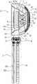
图1是本实用新型便携式风扇第一实施例的立体图;Fig. 1 is the perspective view of the first embodiment of the portable fan of the present invention;
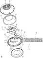
图2是本实用新型便携式风扇第一实施例一个角度的立体分解图;Fig. 2 is the perspective exploded view of the first embodiment of the portable fan of the present invention;
图3是本实用新型便携式风扇第一实施例另一角度的立体分解图;3 is a perspective exploded view of the first embodiment of the portable fan of the present invention from another angle;
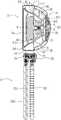
图4是本实用新型便携式风扇第一实施例的剖视图;4 is a cross-sectional view of the first embodiment of the portable fan of the present invention;
图5是本实用新型便携式风扇第二实施例的立体分解图;5 is an exploded perspective view of the second embodiment of the portable fan of the present invention;
图6是本实用新型便携式风扇第二实施例的剖视图。6 is a cross-sectional view of the second embodiment of the portable fan of the present invention.
具体实施方式Detailed ways
为便于更好地理解本实用新型的目的、结构、特征以及功效等,现结合附图和具体实施方式对本实用新型便携式风扇100作进一步说明。In order to facilitate a better understanding of the purpose, structure, features and efficacy of the present invention, the
如图1至图4所示,为本实用新型便携式风扇100,所述便携式风扇100包括风力部1和固定部2,所述固定部2用于将所述风力部1固定于外部。所述风力部1包括进风部11、出风部13和混流风扇3。所述进风部11包括进风罩12以及位于所述进风罩12径向内侧的增压器5,所述进风罩12上设有进风口121。所述出风部13包括加压件4以及连接于所述加压件4径向外侧的出风罩14,所述加压件4的前端和所述出风罩14的前端的径向之间形成出风口141,所述出风部13和所述进风部11前后相配合,且共同形成容置部15。所述混流风扇3收容于所述容置部15,且绕转轴旋转。所述进风口121和所述出风口141相连通,风自所述进风口121进入所述容置部15,后自所述出风口141吹出。As shown in FIG. 1 to FIG. 4 , it is a
如图1至图3所示,在本实施例中,所述固定部2为八爪鱼形式,所述固定部2通过柔性连接的方式将所述风力部1固定于外部,所述固定部2包括支架21、连接部22和三个支腿23,当然,所述支腿23的数量不以此为限制。所述支架21和三个所述支腿23安装在所述连接部22的相对两侧,具体说来,所述支架21安装于所述连接部22的上侧,三个所述支腿23安装在所述连接部22的下侧,并且,所述支架21、所述连接部22和三个所述支腿23三者之间可相对旋转,所述支架21可相对所述连接部22水平旋转,每一所述支腿23均可独自相对与所述连接部22的连接处旋转。As shown in FIG. 1 to FIG. 3 , in this embodiment, the
如图2至图4所示,所述支架21连接于所述风力部1的相对两侧,且自所述风力部1的相对两侧相向延伸,在所述风力部1的下方汇合,并在所述风力部1的下方安装于所述连接部22,所述风力部1可旋转地安装在所述支架21上。三个所述支腿23为挠性的,均可弯折定型,每一所述支腿23包括具有挠性的芯体231及包裹于所述芯体231外侧的套体232,所述芯体231可为铝质,材质软,弯曲后易保持,使得所述支腿23除了能正常支撑外,还能根据不同场景,可以手持、缠绕于其他支撑件上,例如可将所述便携式风扇100弯曲缠绕于婴儿车、摇椅等需要经常更换的儿童产品上,功能丰富灵活。所述套体232为软质胶套,所述套体232的外部还具有防滑纹,便于手持或其他固定方式。当然,所述芯体231和所述套体232的材质并不以此为限制。在其他实施例中,所述固定部2也可以是夹子形式,以通过夹持的方式将所述风力部1固定于外部。As shown in FIG. 2 to FIG. 4 , the
如图2至图4所示,所述混流风扇3包括旋转座31和多个第一叶片32,所述旋转座31包括自后向前径向增大的导风面311,所述导风面311可以整体呈径向增大,也可以部分径向增大,多个所述第一叶片32连接且等距布置于所述导风面311。所述旋转座31大致为截锥状,所述旋转座31在后端的径向截面积小于前端的径向截面积,所述旋转座31形成有开口朝前的收容腔312,外转子无刷电机33收容于所述收容腔312内。在所述旋转座31径向截面积较大的前端,有利于成型开口朝前的所述收容腔312,且易于将所述外转子无刷电机33放入所述收容腔312。所述外转子无刷电机33的使用寿命可达1万5小时,并且没有了有刷电机运转时产生的电火花,可极大减少电火花对遥控无线电设备的干扰;无刷的方式运转时摩擦力大大减小,运行顺畅,降噪效果好。As shown in FIG. 2 to FIG. 4 , the mixed-
如图2至图4所示,所述加压件4包括加压座41和多个第二叶片42,所述加压座41包括自后向前径向增大的加压面411,多个所述第二叶片42连接且等距布置于所述加压面411,且多个所述第二叶片42连接所述出风罩14。所述加压件4还包括前盖43,所述加压座41形成有开口朝前的容纳腔412,电池6收容于所述容纳腔412,所述前盖43遮盖所述容纳腔412。所述电池6收容于所述加压件4内,所述外转子无刷电机33收容于所述混流风扇3内,使所述电池6和所述外转子无刷电机33均收容于所述风力部1,所述便携式风扇100的运作系统较为集中。As shown in FIG. 2 to FIG. 4 , the
如图1、图2和图4所示,所述容纳腔412中还设有开关7和接口8,所述开关7用于启动、调节风速和关闭,所述接口8用于与外部电源连接对所述电池6充电,所述开关7和所述接口8向前显露于所述前盖43。所述前盖43的表面向后凹陷形成凹面,形成负压区(未标识),以减少湍流,从而减少噪音。同时,在其他实施例中,所述前盖43还可以是用于可拆换式设置的IP形象物品(未图示,下同),所述前盖43可外露,或通过至少部分透明材料进行遮盖,以提升用户对IP形象物品的交互。通过设置可拆换式,避免了不同的合作方要定制不同的模具,一套模具就能对接多个IP合作方,能降低40%左右的IP合作方生产成本;外露的IP形象物品,增加用户直接触摸IP形象物品,改变传统的使用体验。所述前盖43也可以用于设置香薰组件,也可以用于设置加湿和香薰结合的组件,也可以是用于收纳USB线束,也可以是用于LED灯的镜子等,并不以此为限制。As shown in FIG. 1 , FIG. 2 and FIG. 4 , the
如图2至图4所示,所述混流风扇3和所述加压件4轴向上紧邻间隔设置,所述旋转座31和所述加压座41在轴向上紧邻间隔设置,所述导风面311和所述加压面411在轴向上紧邻间隔设置。所述导风面311和所述加压面411之间的间隔为1.8-2.2mm(毫米,下同),以隔断所述混流风扇3和所述加压件4之间的间隔,使所述混流风扇3产生的风顺畅地经由所述加压件4,向前流向所述出风口141。所述第一叶片32和所述第二叶片42之间的间隔为1.8-2.2mm,以隔断所述混流风扇3在前端产生的气流沿所述第一叶片32和所述第二叶片42轴向间的间隙回流至后端,减少回流损耗,并隔断相邻两个所述第二叶片42之间的风发生串流,从而梳理气流并增加气压,实现导风、降噪的效果。当然,间隔的具体数值并不以此为限,只要能使所述混流风扇3的风顺畅流向所述出风口141,减少回流损耗即可。As shown in FIG. 2 to FIG. 4 , the mixed-
如图2至图4所示,所述加压座41自后向前径向增大,多个所述第一叶片32轴向上的投影未向外超出所述加压座41的前端的径向截面边缘,也就是说,从前向后看去,从所述出风口141看不到所述第一叶片32,用户也不会看到所述混流风扇3的转动,当使用在婴儿车上时,减少吸引婴儿的注意力,避免婴儿想触碰所述混流风扇3的情况的发生。在一些实施例中,所述加压座41的前端和所述出风罩14的前端之间的径向距离为4-6mm,所述进风口121包括多个圆孔,所述圆孔的半径为1.05-1.45mm,婴儿的指径大约为20-40mm,小开口进一步避免了婴儿的手指伸入的可能性,并且,在所述进风口121和所述出风口141均形成防异物进入的安全孔径。同时,在一些实施例中,所述加压件4的厚度为20-35mm,则自所述进风口121至转动的所述混流风扇3之间具有一定距离,以形成可允许细长异物从所述出风口141进入后无伤的安全空间。当然,应当理解,具体数值并不以此为限制。As shown in FIG. 2 to FIG. 4 , the
如图1、图2和图4所示,所述加压件4的厚度与所述出风罩14的厚度的比值范围为0.5-1,所述加压件4的厚度与所述混流风扇3的厚度的比值范围为0.8-1.2,以使气流经由所述第一叶片32进行高压聚风后,通过所述第二叶片42进行等效距离梳理,确保从所述加压件4产生的最终气流的高压风量和外部的负压风量所构造的最大使用风量,以及所述最大使用风量的聚合送风距离。应当理解,所述加压件4产生的最终气流风压高,可以带动所述壳体外附近的负压空气,从而进一步增大风量。当然,上述比值范围并不以此为限制。As shown in FIG. 1 , FIG. 2 and FIG. 4 , the ratio of the thickness of the
如图2至图4所示,所述增压器5包括朝向所述混流风扇3且自后向前径向增大的增压面51。在本实施例中,所述增压器5的前端与所述进风罩12连接,所述增压器5的后端悬空,所述增压器5与所述进风罩12之间形成过渡区52,所述过渡区52用于吸音降噪和缓存风。所述增压器5连接于所述进风罩12,且位于所述进风罩12的径向内侧,环设于所述混流风扇3的径向外侧,所述增压器5除了具有增压的作用,还有类似隔音玻璃的作用,起到降噪的效果。当然,所述增压器5的前端也可以是连接于所述出风罩14,或者连接于所述进风罩12和所述出风罩14交接的位置,并不以此为限。As shown in FIG. 2 to FIG. 4 , the
如图2至图4所示,所述导风面311和所述加压面411整体形成径向增大的加压斜面M,所述加压斜面M与所述增压面51和所述出风罩14之间形成加压导流通道T。所述导风面311的至少部分和所述加压面411的至少部分径向凹陷形成凹面,以增大所述加压导流通道T的容积,聚集风量。风自所述进风口121进入所述加压导流通道T,经过所述加压斜面M的两段式加压,风压增加且送风距离加大后,自所述出风口141斜向导出。As shown in FIG. 2 to FIG. 4 , the
如图5和图6所示,为本实用新型便携式风扇100第二实施例的立体分解图和剖视图,与第一实施例的不同之处在于:所述增压器5的前后两端均与所述进风罩12连接,所述增压器5与所述进风罩12之间形成所述过渡区52,所述过渡区52用于吸音降噪。当然,所述增压器5的前端也可以连接于所述出风罩14,或者连接于所述进风罩12和所述出风罩14交接的位置。在本实施例中,所述进风口121为格栅分开的多个开口。其他结构和性能与第一实施例基本一致,在此不再赘述。As shown in FIG. 5 and FIG. 6 , it is an exploded perspective view and a cross-sectional view of the second embodiment of the
以上详细说明仅为本实用新型之较佳实施例的说明,非因此局限本实用新型之专利范围,所以,凡运用本创作说明书及图示内容所为之等效技术变化,均包含于本创作之专利范围内。The above detailed description is only the description of the preferred embodiment of the present invention, and is not intended to limit the scope of the patent of the present invention. Therefore, any equivalent technical changes made by using the description and illustrations of this creation are included in this creation. within the scope of the patent.
Claims (10)
Translated fromChineseApplications Claiming Priority (2)
| Application Number | Priority Date | Filing Date | Title |
|---|---|---|---|
| CN2021223506263 | 2021-09-27 | ||
| CN202122350626 | 2021-09-27 |
Publications (1)
| Publication Number | Publication Date |
|---|---|
| CN217502037Utrue CN217502037U (en) | 2022-09-27 |
Family
ID=80305947
Family Applications (24)
| Application Number | Title | Priority Date | Filing Date |
|---|---|---|---|
| CN202122972208.8UActiveCN216742070U (en) | 2021-09-27 | 2021-11-30 | Pressurized mixed flow generator and portable bladeless fan with same |
| CN202111447538.3AActiveCN114183385B (en) | 2021-09-27 | 2021-11-30 | Pressurized mixed flow generator and portable bladeless fan equipped with the same |
| CN202122972198.8UActiveCN216742069U (en) | 2021-09-27 | 2021-11-30 | Pressurized mixed flow generator and portable bladeless fan equipped therewith |
| CN202122972162.XUActiveCN216742067U (en) | 2021-09-27 | 2021-11-30 | Pressurized mixed flow generator and portable bladeless fan with same |
| CN202122980532.4UActiveCN216742072U (en) | 2021-09-27 | 2021-11-30 | Pressurized mixed flow generator and portable bladeless fan with same |
| CN202122974743.7UActiveCN216842288U (en) | 2021-09-27 | 2021-11-30 | Pressurized mixed flow generator and portable bladeless fan equipped therewith |
| CN202111447539.8AActiveCN114183386B (en) | 2021-09-27 | 2021-11-30 | Pressurized mixed flow generator and portable bladeless fan equipped with the same |
| CN202122972174.2UActiveCN216742068U (en) | 2021-09-27 | 2021-11-30 | Mixed flow fan, pressurized mixed flow generator and portable bladeless fan equipped therewith |
| CN202111445161.8AActiveCN114087218B (en) | 2021-09-27 | 2021-11-30 | Handheld bladeless fan |
| CN202123156177.5UActiveCN217029355U (en) | 2021-09-27 | 2021-12-06 | Hand-held fan |
| CN202123124225.2UActiveCN217029352U (en) | 2021-09-27 | 2021-12-10 | Portable bladeless fan |
| CN202123143736.9UActiveCN216518757U (en) | 2021-09-27 | 2021-12-10 | Portable bladeless fan |
| CN202111518220.XAPendingCN114215774A (en) | 2021-09-27 | 2021-12-10 | Portable bladeless fan |
| CN202510930119.7APendingCN120720246A (en) | 2021-09-27 | 2021-12-10 | portable bladeless fan |
| CN202111519414.1APendingCN114215775A (en) | 2021-09-27 | 2021-12-10 | Portable Bladeless Fan |
| CN202123143489.2UActiveCN216518756U (en) | 2021-09-27 | 2021-12-10 | Portable bladeless fan |
| CN202123115702.9UActiveCN217029351U (en) | 2021-09-27 | 2021-12-10 | Portable bladeless fan |
| CN202510923424.3APendingCN120701591A (en) | 2021-09-27 | 2021-12-10 | Portable bladeless fan |
| CN202510922070.0APendingCN120701590A (en) | 2021-09-27 | 2021-12-10 | portable bladeless fan |
| CN202510922055.6APendingCN120626515A (en) | 2021-09-27 | 2021-12-10 | portable bladeless fan |
| CN202111510129.3APendingCN114215773A (en) | 2021-09-27 | 2021-12-10 | Portable Bladeless Fan |
| CN202220207524.8UActiveCN217029363U (en) | 2021-09-27 | 2022-01-25 | Hanging neck type fan |
| CN202220318943.9UActiveCN217502037U (en) | 2021-09-27 | 2022-02-17 | Portable Fan |
| CN202221164340.4UActiveCN217950721U (en) | 2021-09-27 | 2022-05-16 | Portable bladeless fan |
Family Applications Before (22)
| Application Number | Title | Priority Date | Filing Date |
|---|---|---|---|
| CN202122972208.8UActiveCN216742070U (en) | 2021-09-27 | 2021-11-30 | Pressurized mixed flow generator and portable bladeless fan with same |
| CN202111447538.3AActiveCN114183385B (en) | 2021-09-27 | 2021-11-30 | Pressurized mixed flow generator and portable bladeless fan equipped with the same |
| CN202122972198.8UActiveCN216742069U (en) | 2021-09-27 | 2021-11-30 | Pressurized mixed flow generator and portable bladeless fan equipped therewith |
| CN202122972162.XUActiveCN216742067U (en) | 2021-09-27 | 2021-11-30 | Pressurized mixed flow generator and portable bladeless fan with same |
| CN202122980532.4UActiveCN216742072U (en) | 2021-09-27 | 2021-11-30 | Pressurized mixed flow generator and portable bladeless fan with same |
| CN202122974743.7UActiveCN216842288U (en) | 2021-09-27 | 2021-11-30 | Pressurized mixed flow generator and portable bladeless fan equipped therewith |
| CN202111447539.8AActiveCN114183386B (en) | 2021-09-27 | 2021-11-30 | Pressurized mixed flow generator and portable bladeless fan equipped with the same |
| CN202122972174.2UActiveCN216742068U (en) | 2021-09-27 | 2021-11-30 | Mixed flow fan, pressurized mixed flow generator and portable bladeless fan equipped therewith |
| CN202111445161.8AActiveCN114087218B (en) | 2021-09-27 | 2021-11-30 | Handheld bladeless fan |
| CN202123156177.5UActiveCN217029355U (en) | 2021-09-27 | 2021-12-06 | Hand-held fan |
| CN202123124225.2UActiveCN217029352U (en) | 2021-09-27 | 2021-12-10 | Portable bladeless fan |
| CN202123143736.9UActiveCN216518757U (en) | 2021-09-27 | 2021-12-10 | Portable bladeless fan |
| CN202111518220.XAPendingCN114215774A (en) | 2021-09-27 | 2021-12-10 | Portable bladeless fan |
| CN202510930119.7APendingCN120720246A (en) | 2021-09-27 | 2021-12-10 | portable bladeless fan |
| CN202111519414.1APendingCN114215775A (en) | 2021-09-27 | 2021-12-10 | Portable Bladeless Fan |
| CN202123143489.2UActiveCN216518756U (en) | 2021-09-27 | 2021-12-10 | Portable bladeless fan |
| CN202123115702.9UActiveCN217029351U (en) | 2021-09-27 | 2021-12-10 | Portable bladeless fan |
| CN202510923424.3APendingCN120701591A (en) | 2021-09-27 | 2021-12-10 | Portable bladeless fan |
| CN202510922070.0APendingCN120701590A (en) | 2021-09-27 | 2021-12-10 | portable bladeless fan |
| CN202510922055.6APendingCN120626515A (en) | 2021-09-27 | 2021-12-10 | portable bladeless fan |
| CN202111510129.3APendingCN114215773A (en) | 2021-09-27 | 2021-12-10 | Portable Bladeless Fan |
| CN202220207524.8UActiveCN217029363U (en) | 2021-09-27 | 2022-01-25 | Hanging neck type fan |
Family Applications After (1)
| Application Number | Title | Priority Date | Filing Date |
|---|---|---|---|
| CN202221164340.4UActiveCN217950721U (en) | 2021-09-27 | 2022-05-16 | Portable bladeless fan |
Country Status (7)
| Country | Link |
|---|---|
| EP (1) | EP4411144A4 (en) |
| JP (2) | JP7742189B2 (en) |
| KR (1) | KR20240088808A (en) |
| CN (24) | CN216742070U (en) |
| AU (2) | AU2022349651B2 (en) |
| CA (1) | CA3233163A1 (en) |
| WO (1) | WO2023046145A1 (en) |
Families Citing this family (13)
| Publication number | Priority date | Publication date | Assignee | Title |
|---|---|---|---|---|
| CN216742070U (en)* | 2021-09-27 | 2022-06-14 | 深圳市几素科技有限公司 | Pressurized mixed flow generator and portable bladeless fan with same |
| CN220544885U (en)* | 2023-07-24 | 2024-02-27 | 深圳市几素科技有限公司 | Motor drive control circuit of portable fan |
| CN114508498A (en)* | 2022-03-10 | 2022-05-17 | 陈建元 | A multifunctional bladeless hand-held fan |
| CN116965624A (en)* | 2022-04-22 | 2023-10-31 | 深圳市几素科技有限公司 | Portable multifunctional umbrella and air outlet device |
| CN115434959A (en)* | 2022-09-23 | 2022-12-06 | 珠海格力电器股份有限公司 | Bladeless fan |
| AU2023411862B2 (en)* | 2022-12-19 | 2025-10-09 | Shenzhen JISU Technology Co., Ltd | Portable fan, driving circuit for portable fan, and handheld fan |
| JP2025043343A (en)* | 2022-12-19 | 2025-03-28 | 深▲せん▼市几素科技有限公司 | Portable fan, drive circuit for portable fan, and handheld fan |
| WO2024131243A1 (en)* | 2022-12-21 | 2024-06-27 | 深圳市几素科技有限公司 | Portable fan |
| WO2024260079A1 (en)* | 2023-06-23 | 2024-12-26 | 深圳市几素科技有限公司 | Fan module, motor for portable rotating device and high-speed motor |
| TWI879082B (en) | 2023-09-12 | 2025-04-01 | 宏碁股份有限公司 | Axial-flow heat-dissipation fan |
| WO2025108314A1 (en)* | 2023-11-21 | 2025-05-30 | 深圳市几素科技有限公司 | Fan module |
| WO2025154558A1 (en)* | 2024-01-19 | 2025-07-24 | ニデック株式会社 | Impeller and fan device |
| US12180977B2 (en)* | 2024-04-22 | 2024-12-31 | Guangdong Wanyi Electronics Co., Ltd. | High-speed booster fan module |
Family Cites Families (39)
| Publication number | Priority date | Publication date | Assignee | Title |
|---|---|---|---|---|
| TWI278576B (en)* | 2004-10-07 | 2007-04-11 | Sunonwealth Electr Mach Ind Co | Axial-flow heat-dissipating fan for boosting air pressure |
| JP2009191627A (en)* | 2008-02-12 | 2009-08-27 | Calsonic Kansei Corp | Electric fan device |
| CN102937117A (en)* | 2011-08-15 | 2013-02-20 | 任文华 | Bladeless fan |
| KR101255739B1 (en)* | 2012-10-23 | 2013-04-16 | 오승민 | The induced fan for two impeller for jet fan of track type supply air outlet |
| GB2509111B (en)* | 2012-12-20 | 2017-08-09 | Dyson Technology Ltd | A fan |
| CN105736470A (en) | 2013-02-15 | 2016-07-06 | 任文华 | Fan |
| JP6585349B2 (en)* | 2015-01-15 | 2019-10-02 | 富士工業株式会社 | Blower fan, blower and range hood |
| CN205533339U (en)* | 2016-03-09 | 2016-08-31 | 慈溪市附海佳青电器厂 | Domestic no leaf electric fan |
| CN105864887B (en)* | 2016-03-28 | 2018-12-18 | 广东美的制冷设备有限公司 | Air conditioner indoor unit |
| TWI636195B (en)* | 2017-02-07 | 2018-09-21 | 周書賢 | Air supply device |
| CN206582149U (en)* | 2017-03-22 | 2017-10-24 | 应万信 | A kind of hand-held fan |
| CN207621053U (en)* | 2017-11-02 | 2018-07-17 | 深圳市维特世嘉科技有限公司 | A kind of mirror fan |
| US10525371B1 (en)* | 2017-11-22 | 2020-01-07 | Lorraine Melody Hsu | Bladeless bubble fan |
| KR102072755B1 (en)* | 2018-05-15 | 2020-02-03 | 주식회사 휴로 | Portable air cleaning fan |
| CN208686628U (en)* | 2018-08-14 | 2019-04-02 | 东莞市龙晟电子科技有限公司 | a hand-held fan |
| JP7091194B2 (en)* | 2018-08-30 | 2022-06-27 | シャープ株式会社 | Blower |
| KR102425457B1 (en)* | 2018-10-19 | 2022-07-25 | 엘지전자 주식회사 | A Fan Motor |
| CN209053814U (en)* | 2018-11-20 | 2019-07-02 | 宁波富而保智能科技有限公司 | Handheld fan |
| CN211874763U (en)* | 2018-11-29 | 2020-11-06 | 曾固 | A radial out-shaft fluid counter-rotation action device and fan |
| CN209623001U (en)* | 2018-12-04 | 2019-11-12 | 鑫贺精密电子(东莞)有限公司 | A kind of hand-held refrigeration-type fan |
| CN209892472U (en)* | 2019-01-16 | 2020-01-03 | 深圳市火蜂鸟电子商务有限公司 | Spray fan |
| CN109681471B (en)* | 2019-02-14 | 2023-08-29 | 福建雪人股份有限公司 | Spacing assembly for multistage centrifugal compressor |
| KR102181188B1 (en)* | 2019-02-26 | 2020-11-20 | 이호영 | Portable pan and air purifier with the portable fan |
| CN210220096U (en)* | 2019-05-10 | 2020-03-31 | 重庆大学 | A portable bladeless blower based on semiconductor refrigeration |
| CN112303001B (en)* | 2019-08-02 | 2024-11-29 | 珠海格力电器股份有限公司 | Fan subassembly and have its cabinet air conditioner |
| CN210317846U (en)* | 2019-08-23 | 2020-04-14 | 深圳市航科精机技术有限公司 | Portable fan |
| CN211230887U (en)* | 2019-09-09 | 2020-08-11 | 深圳市迪比科电子科技有限公司 | Portable fan of humidification adding fragtant |
| CN211119841U (en)* | 2019-09-30 | 2020-07-28 | 华中科技大学同济医学院附属协和医院 | Multifunctional atomizing fan |
| CN219492703U (en)* | 2019-10-14 | 2023-08-08 | 东莞市叠品科技有限公司 | Connecting arm, fan assembly and fan |
| KR102188518B1 (en)* | 2019-11-28 | 2020-12-08 | 주식회사 명성 | Structure for double contra-rotating fan |
| CN113074141B (en)* | 2020-01-06 | 2023-03-31 | 广东威灵电机制造有限公司 | Diffuser, air supply device and dust collector |
| CN111322260B (en)* | 2020-04-03 | 2024-06-28 | 东莞市嘉木仕电子有限公司 | A handheld fan |
| CN111350700A (en)* | 2020-04-16 | 2020-06-30 | 陈建元 | flow amplifier |
| CN212867982U (en)* | 2020-07-31 | 2021-04-02 | 东莞市盛沃高叶轮机械设计有限公司 | Tube type hand-held fan |
| CN214145972U (en)* | 2020-12-21 | 2021-09-07 | 东莞市盛沃高叶轮机械设计有限公司 | Hand-held bladeless fan |
| CN120759779A (en)* | 2021-03-20 | 2025-10-10 | 陈燕玲 | fan header |
| CN112983867B (en)* | 2021-04-12 | 2025-04-18 | 深圳市星司南电子科技有限公司 | A handheld beauty mirror fan |
| CN216742070U (en)* | 2021-09-27 | 2022-06-14 | 深圳市几素科技有限公司 | Pressurized mixed flow generator and portable bladeless fan with same |
| CN216742071U (en)* | 2021-11-30 | 2022-06-14 | 深圳市几素科技有限公司 | Pressurized mixed flow generator and portable bladeless fan equipped therewith |
- 2021
- 2021-11-30CNCN202122972208.8Upatent/CN216742070U/enactiveActive
- 2021-11-30CNCN202111447538.3Apatent/CN114183385B/enactiveActive
- 2021-11-30CNCN202122972198.8Upatent/CN216742069U/enactiveActive
- 2021-11-30CNCN202122972162.XUpatent/CN216742067U/enactiveActive
- 2021-11-30CNCN202122980532.4Upatent/CN216742072U/enactiveActive
- 2021-11-30CNCN202122974743.7Upatent/CN216842288U/enactiveActive
- 2021-11-30CNCN202111447539.8Apatent/CN114183386B/enactiveActive
- 2021-11-30CNCN202122972174.2Upatent/CN216742068U/enactiveActive
- 2021-11-30CNCN202111445161.8Apatent/CN114087218B/enactiveActive
- 2021-12-06CNCN202123156177.5Upatent/CN217029355U/enactiveActive
- 2021-12-10CNCN202123124225.2Upatent/CN217029352U/enactiveActive
- 2021-12-10CNCN202123143736.9Upatent/CN216518757U/enactiveActive
- 2021-12-10CNCN202111518220.XApatent/CN114215774A/enactivePending
- 2021-12-10CNCN202510930119.7Apatent/CN120720246A/enactivePending
- 2021-12-10CNCN202111519414.1Apatent/CN114215775A/enactivePending
- 2021-12-10CNCN202123143489.2Upatent/CN216518756U/enactiveActive
- 2021-12-10CNCN202123115702.9Upatent/CN217029351U/enactiveActive
- 2021-12-10CNCN202510923424.3Apatent/CN120701591A/enactivePending
- 2021-12-10CNCN202510922070.0Apatent/CN120701590A/enactivePending
- 2021-12-10CNCN202510922055.6Apatent/CN120626515A/enactivePending
- 2021-12-10CNCN202111510129.3Apatent/CN114215773A/enactivePending
- 2022
- 2022-01-25CNCN202220207524.8Upatent/CN217029363U/enactiveActive
- 2022-02-17CNCN202220318943.9Upatent/CN217502037U/enactiveActive
- 2022-05-16CNCN202221164340.4Upatent/CN217950721U/enactiveActive
- 2022-09-26EPEP22872189.0Apatent/EP4411144A4/enactivePending
- 2022-09-26JPJP2024519102Apatent/JP7742189B2/enactiveActive
- 2022-09-26KRKR1020247011777Apatent/KR20240088808A/enactivePending
- 2022-09-26AUAU2022349651Apatent/AU2022349651B2/enactiveActive
- 2022-09-26WOPCT/CN2022/121246patent/WO2023046145A1/ennot_activeCeased
- 2022-09-26CACA3233163Apatent/CA3233163A1/enactivePending
- 2024
- 2024-12-12AUAU2024278338Apatent/AU2024278338A1/enactivePending
- 2025
- 2025-05-30JPJP2025090653Apatent/JP2025128214A/enactivePending
Also Published As
Similar Documents
| Publication | Publication Date | Title |
|---|---|---|
| CN217502037U (en) | Portable Fan | |
| US20110010958A1 (en) | Quiet hair dryer | |
| CN111441970A (en) | Handheld Bladeless Fan | |
| CN220539890U (en) | Fan module and blowing device | |
| CN104074159A (en) | Handheld blower | |
| CN211510824U (en) | Electric hair drier with novel structure | |
| CN104074158A (en) | Handheld blower | |
| CN118746011A (en) | Portable fan | |
| CN217518882U (en) | Fan with cooling device | |
| CN219020445U (en) | Personal Care Appliances | |
| CN217885334U (en) | Motor and hair dryer | |
| CN201806125U (en) | Mute air inlet device of electric hair drier | |
| WO2018098864A1 (en) | Air guide ring structure, air conditioner indoor unit and air conditioner | |
| CN217267182U (en) | Backpack hair-dryer | |
| CN205677860U (en) | Centrifugal impeller hair dryer | |
| CN223270215U (en) | Fan module and fan | |
| CN218065069U (en) | Novel warm air blower | |
| CN223035311U (en) | Handheld fan | |
| CN215808787U (en) | A wind-gathering silent heater | |
| CN215949869U (en) | Centrifugal fans and range hoods | |
| CN120021565A (en) | A low-noise, high-speed pet hair dryer |
Legal Events
| Date | Code | Title | Description |
|---|---|---|---|
| GR01 | Patent grant | ||
| GR01 | Patent grant |