CN217470540U - Image capture device and door assembly for image capture device - Google Patents
Image capture device and door assembly for image capture deviceDownload PDFInfo
- Publication number
- CN217470540U CN217470540UCN202090000858.7UCN202090000858UCN217470540UCN 217470540 UCN217470540 UCN 217470540UCN 202090000858 UCN202090000858 UCN 202090000858UCN 217470540 UCN217470540 UCN 217470540U
- Authority
- CN
- China
- Prior art keywords
- biasing member
- door
- image capture
- capture device
- slider
- Prior art date
- Legal status (The legal status is an assumption and is not a legal conclusion. Google has not performed a legal analysis and makes no representation as to the accuracy of the status listed.)
- Active
Links
Images


Classifications
- H—ELECTRICITY
- H05—ELECTRIC TECHNIQUES NOT OTHERWISE PROVIDED FOR
- H05K—PRINTED CIRCUITS; CASINGS OR CONSTRUCTIONAL DETAILS OF ELECTRIC APPARATUS; MANUFACTURE OF ASSEMBLAGES OF ELECTRICAL COMPONENTS
- H05K5/00—Casings, cabinets or drawers for electric apparatus
- H05K5/02—Details
- H05K5/0217—Mechanical details of casings
- H05K5/0221—Locks; Latches
- G—PHYSICS
- G03—PHOTOGRAPHY; CINEMATOGRAPHY; ANALOGOUS TECHNIQUES USING WAVES OTHER THAN OPTICAL WAVES; ELECTROGRAPHY; HOLOGRAPHY
- G03B—APPARATUS OR ARRANGEMENTS FOR TAKING PHOTOGRAPHS OR FOR PROJECTING OR VIEWING THEM; APPARATUS OR ARRANGEMENTS EMPLOYING ANALOGOUS TECHNIQUES USING WAVES OTHER THAN OPTICAL WAVES; ACCESSORIES THEREFOR
- G03B17/00—Details of cameras or camera bodies; Accessories therefor
- G03B17/02—Bodies
- G03B17/08—Waterproof bodies or housings
- H—ELECTRICITY
- H01—ELECTRIC ELEMENTS
- H01M—PROCESSES OR MEANS, e.g. BATTERIES, FOR THE DIRECT CONVERSION OF CHEMICAL ENERGY INTO ELECTRICAL ENERGY
- H01M50/00—Constructional details or processes of manufacture of the non-active parts of electrochemical cells other than fuel cells, e.g. hybrid cells
- H01M50/20—Mountings; Secondary casings or frames; Racks, modules or packs; Suspension devices; Shock absorbers; Transport or carrying devices; Holders
- H01M50/271—Lids or covers for the racks or secondary casings
- H—ELECTRICITY
- H05—ELECTRIC TECHNIQUES NOT OTHERWISE PROVIDED FOR
- H05K—PRINTED CIRCUITS; CASINGS OR CONSTRUCTIONAL DETAILS OF ELECTRIC APPARATUS; MANUFACTURE OF ASSEMBLAGES OF ELECTRICAL COMPONENTS
- H05K5/00—Casings, cabinets or drawers for electric apparatus
- H05K5/02—Details
- H05K5/03—Covers
Landscapes
- Physics & Mathematics (AREA)
- General Physics & Mathematics (AREA)
- Engineering & Computer Science (AREA)
- Microelectronics & Electronic Packaging (AREA)
- Chemical & Material Sciences (AREA)
- Chemical Kinetics & Catalysis (AREA)
- Electrochemistry (AREA)
- General Chemical & Material Sciences (AREA)
- Studio Devices (AREA)
Abstract
Translated fromChinese
Description
Translated fromChinese技术领域technical field
本公开大体涉及图像捕获设备,更具体涉及一种图像捕获设备,包括可移除门组件,该可移除门组件可在关闭位置与打开位置之间重新定位以隐藏、保护和暴露图像捕获设备的内部部件。The present disclosure relates generally to image capture devices, and more particularly to an image capture device including a removable door assembly repositionable between a closed position and an open position to conceal, protect and expose the image capture device of internal components.
背景技术Background technique
图像捕获设备通常包括多个门,该多个门用于隐藏各种内部部件,诸如例如,用于图像捕获设备的功率源(例如,一个或多个电池);一个或多个附件端口;IO接口;USB-C连接器等。然而,包括多个门需要多个密封件(每个门一个密封件),并且存在水和/或碎屑可能进入图像捕获设备的风险升高。附加地,在已知图像捕获设备中,门通常被被固定地连接到图像捕获设备的主体(即,不可从主体移除)。Image capture devices typically include multiple doors for concealing various internal components such as, for example, a power source for the image capture device (eg, one or more batteries); one or more accessory ports; IO interface; USB-C connector, etc. However, including multiple doors requires multiple seals (one seal per door), and there is an increased risk that water and/or debris may enter the image capture device. Additionally, in known image capture devices, the door is typically fixedly attached to the body of the image capture device (ie, not removable from the body).
为了解决这些问题,本公开描述了包括单个可移除门的图像捕获设备,该单个可移除门包括集成密封构件。To address these issues, the present disclosure describes an image capture device that includes a single removable door that includes an integrated sealing member.
发明内容SUMMARY OF THE INVENTION
在本公开的一个方面中,公开了一种图像捕获设备,包括:主体,该主体限定外围腔;以及门组件,该门组件可在打开位置与关闭位置之间移动以关闭或密封外围腔。该门组件包括:限定窗口的门体;滑块,该滑块延伸到窗口中,该滑块由门体支撑以便在第一位置与第二位置之间轴向移动;偏置构件,该偏置构件被配置为与滑块接合(接触);门锁,包括止挡件,该止挡件被配置为与偏置构件接合(接触);以及密封件,该密封件被固定地连接到门锁。In one aspect of the present disclosure, an image capture device is disclosed comprising: a body defining a peripheral cavity; and a door assembly movable between an open position and a closed position to close or seal the peripheral cavity. The door assembly includes: a door body defining a window; a slider extending into the window, the slider supported by the door body for axial movement between a first position and a second position; a biasing member, the biasing member a setting member configured to engage (contact) with the slider; a door lock including a stopper configured to engage (contact) the biasing member; and a seal fixedly connected to the door Lock.
当滑块处于第一位置时,门体相对于图像捕获设备的主体被轴向地固定,以阻止门组件从关闭位置移动到打开位置,并且当滑块处于第二位置时,门体相对于图像捕获设备的主体轴向可移动,以允许门组件从关闭位置移动到打开位置。When the slider is in the first position, the door body is axially fixed relative to the body of the image capture device to prevent movement of the door assembly from the closed position to the open position, and when the slider is in the second position, the door body is axially fixed relative to the body of the image capture device to prevent movement of the door assembly from the closed position to the open position. The body of the image capture device is axially movable to allow the door assembly to move from a closed position to an open position.
偏置构件被配置为与滑块接合(接触),使得滑块的轴向移动使得偏置构件从正常配置偏转到偏转配置。附加地,偏置构件被轴向地固定到门体,使得门体的轴向移动使得偏置构件的对应轴向移动。The biasing member is configured to engage (contact) the slider such that axial movement of the slider deflects the biasing member from the normal configuration to the deflected configuration. Additionally, the biasing member is axially secured to the door body such that axial movement of the door body causes corresponding axial movement of the biasing member.
门锁包括止挡件,该止挡件被配置为在正常配置中与偏置构件接合(接触),以阻止偏置构件和门体的轴向移动。然而,在从正常配置移动到偏转配置期间,偏置构件的偏转使得偏置构件移动离开与止挡件的接合(接触),以允许偏置构件和门体的轴向移动。The door lock includes a stop configured to engage (contact) the biasing member in a normal configuration to prevent axial movement of the biasing member and the door body. However, during movement from the normal configuration to the deflected configuration, deflection of the biasing member causes the biasing member to move out of engagement (contact) with the stopper to allow axial movement of the biasing member and door.
密封构件被固定地连接到门锁,使得门锁、偏置构件和滑块定位在门体与密封构件之间。密封构件包括弹性材料并且被定位为使得在门组件从打开位置移动到关闭位置期间密封构件被压缩在外围腔内,以当门组件处于关闭位置时,在门组件与图像捕获设备的主体之间形成密封。The sealing member is fixedly connected to the door lock such that the door lock, biasing member and slider are positioned between the door body and the sealing member. The sealing member includes a resilient material and is positioned such that the sealing member is compressed within the peripheral cavity during movement of the door assembly from the open position to the closed position to be between the door assembly and the body of the image capture device when the door assembly is in the closed position form a seal.
在某些实施例中,门体可在锁定位置与解锁位置之间轴向移动。在某些实施例中,当门体处于锁定位置时,门组件可以相对于图像捕获设备的主体旋转固定,并且当门体处于解锁位置时,门组件可以相对于图像捕获设备的主体旋转,以允许门组件从关闭位置移动到打开位置。在某些实施例中,门体可以包括锁定构件,该锁定构件被配置为当门体处于锁定位置时,与由图像捕获设备的主体所限定的容座接合(接触)。在某些实施例中,当门体处于解锁位置时,锁定构件可以与容座分离。在某些实施例中,偏置构件可以包括保持结构,该保持结构被配置为与门锁上的止挡件接触。在某些实施例中,当偏置构件处于正常配置时,保持结构和门锁上的止挡件可以轴向对准,以阻止偏置构件和门体的轴向移动。在这样的实施例中,偏置构件移动进入偏转配置可以使得保持结构和止挡件之间的轴向错位,以允许偏置构件和门体的轴向移动。在某些实施例中,保持结构可以包括成对翼部,该成对翼部从偏置构件的主体部分横向向外延伸。在某些实施例中,该成对翼部可以被配置为定位在由门锁限定的对应通道内,以阻止偏置构件和门体沿大致正交于门组件的纵向轴线的轴线远离密封构件移动。在某些实施例中,滑块可以包括偏转器,该偏转器被配置为与偏置构件接合(接触),以当滑块从第一位置移动到第二位置时,促进偏置构件朝向门锁偏转。在某些实施例中,该偏置构件可以限定被配置为接纳滑块的开口。In certain embodiments, the door body is axially movable between a locked position and an unlocked position. In some embodiments, the door assembly may be rotationally fixed relative to the body of the image capture device when the door body is in the locked position, and may be rotated relative to the body of the image capture device when the door body is in the unlocked position to Allows the door assembly to move from the closed position to the open position. In certain embodiments, the door body may include a locking member configured to engage (contact) a receptacle defined by the body of the image capture device when the door body is in the locked position. In certain embodiments, the locking member may be disengaged from the receptacle when the door body is in the unlocked position. In certain embodiments, the biasing member may include a retaining structure configured to contact a stop on the door lock. In certain embodiments, stops on the retaining structure and the door lock may be axially aligned to prevent axial movement of the biasing member and door body when the biasing member is in the normal configuration. In such embodiments, movement of the biasing member into the deflected configuration may cause axial misalignment between the retaining structure and the stop to allow axial movement of the biasing member and door body. In certain embodiments, the retention structure may include a pair of wings extending laterally outward from the body portion of the biasing member. In certain embodiments, the pair of wings may be configured to be positioned within corresponding passages defined by the door latch to prevent the biasing member and door body from moving away from the sealing member along an axis generally orthogonal to the longitudinal axis of the door assembly move. In certain embodiments, the slider may include a deflector configured to engage (contact) the biasing member to urge the biasing member toward the door when the slider is moved from the first position to the second position Lock deflection. In certain embodiments, the biasing member may define an opening configured to receive the slider.
在某些实施例中,滑块可以包括倾斜(angled)表面,该倾斜表面被配置为与限定偏置构件中的开口的端壁接合(接触),以当滑块从第一位置移动到第二位置时,促进偏置构件偏转。在某些实施例中,密封构件可以限定通道,该通道被配置为接纳从偏置构件延伸的指状物。在某些实施例中,通道可以限定端壁,该端壁被配置为与指状物接合(接触),以便阻止偏置构件和门体的继续轴向移动。在某些实施例中,密封构件可以经由门锁和偏置构件间接连接到门体上。在某些实施例中,密封构件可以包括接合结构,该接合结构被配置为将密封构件可旋转地连接并且轴向地固定到图像捕获设备的主体,使得门组件在打开位置与关闭位置之间的移动期间相对于图像捕获设备的主体是可旋转的。在某些实施例中,图像捕获设备还可以包括一个或多个功率源;配件端口;I/O接口;以及USB-C连接器。在这样的实施例中,当门组件处于打开位置时,功率源、附件端口、I/O接口和/或USB-C连接器可以被定位为用于经由外围腔访问。可以想象,上文所描述的图像捕获设备可以包括本段落中描述的特征和元件的任何组合。In certain embodiments, the slider may include an angled surface configured to engage (contact) an end wall defining an opening in the biasing member for when the slider is moved from the first position to the second position In the second position, deflection of the biasing member is facilitated. In certain embodiments, the sealing member may define a channel configured to receive a finger extending from the biasing member. In certain embodiments, the channel may define an end wall configured to engage (contact) the finger so as to prevent continued axial movement of the biasing member and door. In certain embodiments, the sealing member may be indirectly connected to the door body via the door lock and biasing member. In certain embodiments, the sealing member may include an engagement structure configured to rotatably connect and axially secure the sealing member to the body of the image capture device such that the door assembly is between an open position and a closed position is rotatable relative to the body of the image capture device during movement. In some embodiments, the image capture device may also include one or more power sources; accessory ports; I/O interfaces; and a USB-C connector. In such an embodiment, the power source, accessory port, I/O interface, and/or USB-C connector may be positioned for access via the peripheral cavity when the door assembly is in the open position. It is envisioned that the image capture devices described above may include any combination of the features and elements described in this paragraph.
在本公开的另一方面中,公开了一种用于图像捕获设备的门组件。该门组件包括:密封构件,该密封构件能够可释放地连接到图像捕获设备并且被配置为在门组件关闭时,与图像捕获设备形成密封;门锁,该门锁固定到密封构件;偏置构件,该偏置构件由门锁接纳;门体,该门体可相对于图像捕获设备沿着第一移动轴线在锁定位置与解锁位置之间轴向移动;以及滑块,该滑块由门体支撑。In another aspect of the present disclosure, a door assembly for an image capture device is disclosed. The door assembly includes: a sealing member releasably connectable to the image capture device and configured to form a seal with the image capture device when the door assembly is closed; a door lock secured to the sealing member; a bias a member received by the door lock; a door body axially movable relative to the image capture device along a first axis of movement between a locked position and an unlocked position; and a slider supported by the door body support.
当门体处于锁定位置时,门组件相对于图像捕获设备可旋转地固定;而当门体处于解锁位置时,门组件相对于图像捕获设备可旋转以允许打开门组件。门体被固定地连接到偏置构件,使得门体的轴向移动引起偏置构件的对应轴向移动。When the door body is in the locked position, the door assembly is rotatably fixed relative to the image capture device; and when the door body is in the unlocked position, the door assembly is rotatable relative to the image capture device to allow the door assembly to be opened. The door body is fixedly connected to the biasing member such that axial movement of the door body causes corresponding axial movement of the biasing member.
滑块由门体支撑,以促进滑块沿着第二移动轴线的轴向移动,该第二移动轴线大致平行于第一移动轴线延伸。滑块被配置为与偏置构件接合(接触),使得滑块在第一位置与第二位置之间的移动使得偏置构件在正常配置与偏转配置之间偏转。当偏置构件处于正常配置时,偏置构件和门体相对于图像捕获设备轴向地固定,并且当偏置构件处于偏转配置时,偏置构件和门体相对于图像捕获设备轴向可移动,使得滑块进入第二位置的移动促进打开门组件。The slide is supported by the door to facilitate axial movement of the slide along a second axis of movement extending substantially parallel to the first axis of movement. The slider is configured to engage (contact) the biasing member such that movement of the slider between the first position and the second position deflects the biasing member between the normal configuration and the deflected configuration. When the biasing member is in the normal configuration, the biasing member and door are axially fixed relative to the image capture device, and when the biasing member is in the deflected configuration, the biasing member and door are axially movable relative to the image capture device , such that movement of the slider into the second position facilitates opening the door assembly.
在某些实施例中,门锁可以包括成对止挡件,并且偏置构件可以包括成对翼部,当偏置构件处于正常配置时,该成对翼部与成对止挡件轴向对准,使得成对止挡件与成对翼部之间的接合(接触) 阻止偏置构件和门体的轴向移动。在这样的实施例中,偏置构件移动进入偏转配置可以使得成对翼部移动离开与成对止挡件的轴向对准,以允许偏置构件和门体的轴向移动。在某些实施例中,成对翼部可以被配置为定位在由门锁限定的对应通道内,以阻止偏置构件和门体沿着大致正交于门组件的纵向轴线的轴线远离密封构件移动。在某些实施例中,滑块可以包括偏转器,该偏转器被配置为与偏置构件接合(接触),以在滑块从第一位置轴向移动到第二位置以及成对翼部移动脱离与成对止挡件的轴向对准期间、促进偏置构件偏转。在某些实施例中,该偏置构件可以限定被配置为接纳滑块的开口。在某些实施例中,滑块可以包括倾斜表面,该倾斜表面被配置为与限定偏置构件中的开口的端壁接合(接触),以当滑块从第一位置移动到第二位置时,促进偏置构件偏转。在某些实施例中,该密封构件可以限定通道,该通道被配置为接纳从偏置构件延伸的指状物。在某些实施例中,该通道可以限定端壁,该端壁被配置为与指状物接合(接触),以便阻止偏置构件和门体的继续轴向移动。可以想象,上文所描述的门组件可以包括在本段落中描述的特征和元件的任何组合。In certain embodiments, the door lock may include a pair of stops, and the biasing member may include a pair of wings that are axially axial to the pair of stops when the biasing member is in the normal configuration Aligned such that engagement (contact) between the pair of stops and the pair of wings prevents axial movement of the biasing member and door body. In such embodiments, movement of the biasing member into the deflected configuration may cause the pair of wings to move out of axial alignment with the pair of stops to allow axial movement of the biasing member and door body. In certain embodiments, the pair of wings may be configured to be positioned within corresponding channels defined by the door latch to prevent the biasing member and door body from moving away from the sealing member along an axis generally orthogonal to the longitudinal axis of the door assembly move. In certain embodiments, the slider may include a deflector configured to engage (contact) the biasing member for axial movement of the slider from the first position to the second position and movement of the pair of wings Deflection of the biasing member is facilitated during disengagement from axial alignment with the pair of stops. In certain embodiments, the biasing member may define an opening configured to receive the slider. In certain embodiments, the slider may include a ramped surface configured to engage (contact) an end wall defining an opening in the biasing member, when the slider is moved from the first position to the second position , which facilitates deflection of the biasing member. In certain embodiments, the sealing member can define a channel configured to receive a finger extending from the biasing member. In certain embodiments, the channel may define an end wall configured to engage (contact) the finger so as to prevent continued axial movement of the biasing member and door. It is envisioned that the door assemblies described above may include any combination of the features and elements described in this paragraph.
在本公开的另一方面中,公开了一种包括门组件的图像捕获设备的组装方法。该方法包括:通过将图像捕获设备上的枢转构件插入门组件的密封构件上的夹中以允许门组件在打开和关闭期间相对于图像捕获设备的主体旋转,而将门组件可移除地连接到图像捕获设备;将门锁固定安装到密封构件;将偏置构件定位在门锁内;将滑块连接到门体;以及将偏置构件固定地连接到门体。In another aspect of the present disclosure, a method of assembling an image capture device including a door assembly is disclosed. The method includes removably connecting the door assembly by inserting a pivot member on the image capture device into a clip on a sealing member of the door assembly to allow the door assembly to rotate relative to a body of the image capture device during opening and closing to an image capture device; fixedly mounting the door lock to the sealing member; positioning the biasing member within the door lock; attaching the slider to the door body; and fixedly attaching the biasing member to the door body.
滑块可相对于门体轴向移动,并且被配置为与偏置构件接合(接触),使得滑块的轴向移动经由门体使得偏置构件的对应轴向移动。The slider is axially movable relative to the door body and is configured to engage (contact) the biasing member such that axial movement of the slider causes corresponding axial movement of the biasing member via the door body.
偏置构件连接到门体,使得门体在门组件的锁定和解锁期间的轴向移动使得偏置构件的对应轴向移动。The biasing member is connected to the door body such that axial movement of the door body during locking and unlocking of the door assembly results in corresponding axial movement of the biasing member.
在某些实施例中,将滑块和偏置构件连接到门体可以包括:定位滑块和偏置构件,使得在门组件的锁定和解锁期间,滑块可沿着第一移动轴线移动,而偏置构件和门体可沿着第二移动轴线移动,该第二移动轴线与第一移动轴线大致平行延伸。在某些实施例中,将偏置构件连接到门体可以包括:将偏置构件连接到门体,使得滑块的轴向移动使得偏置构件沿着移动轴线偏转,该移动轴线大致正交于第一移动轴线和第二移动轴线中的每个移动轴线延伸。可以设想,上文所描述的方法可以包括本段落中描述的特征、元件和/或任务的任何组合。In certain embodiments, connecting the slider and the biasing member to the door body may include positioning the slider and the biasing member such that the slider is movable along the first axis of movement during locking and unlocking of the door assembly, Instead, the biasing member and the door body are movable along a second axis of movement that extends generally parallel to the first axis of movement. In certain embodiments, connecting the biasing member to the door body may include connecting the biasing member to the door body such that axial movement of the slider deflects the biasing member along an axis of movement that is substantially orthogonal Extends on each of the first movement axis and the second movement axis. It is contemplated that the methods described above may include any combination of the features, elements and/or tasks described in this paragraph.
根据本公开实施例的当图像捕获设备和用于图像捕获设备的门组件能够方便地实现门体的解锁和锁定并且能够确保密封性能。The image capturing device and the door assembly for the image capturing device according to the embodiments of the present disclosure can conveniently realize the unlocking and locking of the door body and can ensure the sealing performance.
附图说明Description of drawings
当结合附图阅读时,根据以下具体实施方式以最佳方式理解本公开。应当强调,根据惯例,附图的各个特征并非按比例绘制。相反,为了清楚起见,各种特征的尺寸被任意扩大或缩小。The present disclosure is best understood in light of the following detailed description when read in conjunction with the accompanying drawings. It should be emphasized that, according to common practice, the various features of the drawings are not drawn to scale. On the contrary, the dimensions of the various features are arbitrarily expanded or reduced for clarity.
图1A至图1D是图像捕获设备的一个示例的等轴视图。1A-1D are isometric views of one example of an image capture device.
图2A至图2B是图像捕获设备的另一示例的等轴视图。2A-2B are isometric views of another example of an image capture device.
图2C是图2A至图2B的图像捕获设备的横截面视图。2C is a cross-sectional view of the image capture device of FIGS. 2A-2B.
图3A至图3B是图像捕获系统的示例的框图。3A-3B are block diagrams of examples of image capture systems.
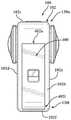
图4A是包括根据本公开的原理的门组件的图像捕获设备的侧平面图,门组件被示为处于关闭锁定位置。4A is a side plan view of an image capture device including a door assembly shown in a closed locked position in accordance with the principles of the present disclosure.
图4B是图像捕获设备的前透视图,门组件被示为处于关闭锁定位置。4B is a front perspective view of the image capture device with the door assembly shown in a closed locked position.
图4C是图像捕获设备的侧平面图,门组件被示为处于关闭解锁位置。4C is a side plan view of the image capture device with the door assembly shown in a closed, unlocked position.
图4D是图像捕获设备的侧平面图,门组件被示为处于打开位置。4D is a side plan view of the image capture device with the door assembly shown in an open position.
图4E是图像捕获设备的前平面图,门组件被示为处于打开位置。4E is a front plan view of the image capture device with the door assembly shown in an open position.
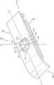
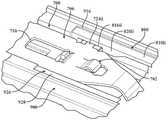
图5是图示了门组件与图像捕获设备的连接的局部(竖直)横截面视图,其中门组件被示为处于解锁位置。5 is a partial (vertical) cross-sectional view illustrating the connection of the door assembly to the image capture device, with the door assembly shown in an unlocked position.
图6是与图像捕获设备分离的门组件的侧透视图。6 is a side perspective view of the door assembly separated from the image capture device.
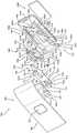
图7是门组件的顶透视图,其中零件分离。Figure 7 is a top perspective view of the door assembly with the parts separated.
图8是门组件的底透视图,其中零件分离。Figure 8 is a bottom perspective view of the door assembly with the parts separated.
图9是示出了门组件处于锁定位置的局部(竖直)横截面视图。Figure 9 is a partial (vertical) cross-sectional view showing the door assembly in a locked position.
图10是示出了处于锁定位置的门组件的局部顶透视图。Figure 10 is a partial top perspective view showing the door assembly in the locked position.
图11是示出了处于解锁位置的门组件的局部(竖直)横截面视图。Figure 11 is a partial (vertical) cross-sectional view showing the door assembly in an unlocked position.
图12是示出了处于解锁位置的门组件的局部透视(竖直)横截面视图。12 is a partial perspective (vertical) cross-sectional view showing the door assembly in an unlocked position.
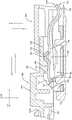
图13是被示为连接到处于关闭锁定位置的图像捕获设备的门组件的局部(竖直)横截面视图。13 is a partial (vertical) cross-sectional view of a door assembly shown connected to the image capture device in a closed, locked position.
图14是被示为连接到处于关闭锁定位置的图像捕获设备的门组件的局部(水平)横截面视图。14 is a partial (horizontal) cross-sectional view of a door assembly shown connected to the image capture device in a closed, locked position.
具体实施方式Detailed ways
本公开描述了图像捕获设备以及与其一起使用的门组件的各种实施例。本文中所描述的门组件被配置为可移除地连接到图像捕获设备并且在打开位置与关闭位置之间可移动以隐藏和准许访问图像捕获设备的各种内部部件,这些内部部件包括:例如功率源(例如,一个或多个电池);一个或多个附件端口;I/O接口;USB-C连接器等。为了防止(如果并非完全防止)碎屑和/或水进入,本文中所描述的门组件包括密封构件,该密封构件被配置为在关闭时与图像捕获设备的主体形成(防水)密封。The present disclosure describes various embodiments of image capture devices and door assemblies for use therewith. The door assemblies described herein are configured to be removably attached to the image capture device and moveable between open and closed positions to conceal and grant access to various internal components of the image capture device, including, for example: A power source (eg, one or more batteries); one or more accessory ports; I/O interfaces; USB-C connectors, etc. To prevent, if not completely prevent, the ingress of debris and/or water, the door assemblies described herein include a sealing member configured to form a (waterproof) seal with the body of the image capture device when closed.
除了密封构件之外,本文中所描述的门组件包括:门体,该门体在锁定位置与解锁位置之间可移动(例如,可滑动);偏置构件 (例如,弹簧夹),该偏置构件被固定地连接到门体;门锁,该门锁阻止门体轴向移动,从而阻止偏置构件轴向移动;滑块,该滑块由门体支撑,用于在第一位置与第二位置之间轴向移动;以及间隔件。In addition to the sealing member, the door assemblies described herein include: a door body that is movable (eg, slidable) between a locked position and an unlocked position; a biasing member (eg, a spring clip) that biases The setting member is fixedly connected to the door body; the door lock prevents the door body from moving axially, thereby preventing the biasing member from moving axially; axial movement between the second positions; and a spacer.
在锁定位置中,门体接合(接触)图像捕获设备的主体以阻止打开门组件,而在解锁位置中,门体与图像捕获设备的主体脱离(不接触)以准许打开门组件。然而,门体的轴向移动经由偏置构件与门锁上的止挡件之间的接合(接触)而被约束,直至滑块移动到第二位置为止,从而阻止(如果并非完全防止)门体无意(例如,意外或非想要)移动到解锁位置(例如,在图像捕获设备掉落的情况下),因此导致门组件无意(例如,意外或非想要)打开。In the locked position, the door body engages (contacts) the body of the image capture device to prevent opening of the door assembly, while in the unlocked position, the door body disengages (out of contact) with the body of the image capture device to permit opening of the door assembly. However, axial movement of the door body is restrained via engagement (contact) between the biasing member and a stop on the door lock until the slider moves to the second position, preventing, if not completely preventing, the door The body is inadvertently (eg, accidentally or unintended) moved to the unlocked position (eg, in the event that the image capture device is dropped), thereby causing the door assembly to open unintentionally (eg, accidentally or unintendedly).
当滑块从第一位置移动到第二位置时,滑块使得偏置构件从正常配置偏转到偏转配置。在偏转配置中,偏置构件移动解除与门锁上的止挡件的接合(接触),这允许偏置构件轴向移动,因此允许门体解锁门组件。The slider deflects the biasing member from the normal configuration to the deflected configuration when the slider moves from the first position to the second position. In the deflected configuration, the biasing member moves out of engagement (contact) with the stop on the door lock, which allows the biasing member to move axially, thus allowing the door body to unlock the door assembly.
间隔件由密封构件支撑(例如,安装到密封构件),以减少(如果并非完全消除)门组件的部件之间的非期望相对移动。附加地或可替代地,间隔件可以在门组件关闭时增强在密封构件与图像捕获设备之间形成的密封;增加冲击吸收;和/或增强图像捕获设备的部件之间的电连接性。The spacers are supported by the sealing member (eg, mounted to the sealing member) to reduce, if not completely eliminate, undesired relative movement between the components of the door assembly. Additionally or alternatively, the spacers may enhance the seal formed between the sealing member and the image capture device when the door assembly is closed; increase shock absorption; and/or enhance electrical connectivity between components of the image capture device.
图1A至图1D是图像捕获设备100的示例的等轴视图。图像捕获设备100可以包括主体102,该主体102具有构造在主体102的前表面上的透镜104、主体102的前表面上的各种指示器(诸如LED、显示器等)、各种输入机构(诸如按钮、开关和触摸屏机构)、以及主体102内部的电子器件(例如,成像电子器件、功率电子器件等)(用于经由透镜104捕获图像和/或执行其他功能)。图像捕获设备100可以被配置为捕获图像和视频并存储所捕获的图像和视频以用于后续显示或回放。1A-1D are isometric views of examples of
图像捕获设备100可以包括各种指示器,包括LED灯106和LCD 显示器108。图像捕获设备100还可以包括按钮110,该按钮110被配置为允许图像捕获设备100的用户与图像捕获设备100交互,以打开图像捕获设备100,操作与图像捕获设备100的门相关联的闩锁或铰链,和/或以其他方式配置图像捕获设备100的操作模式。图像捕获设备100还可以包括麦克风112,该麦克风112被配置为接收和记录音频信号以及记录视频。
图像捕获设备100可以包括I/O接口114(例如,如使用虚线所指示地隐藏)。如图1B中最佳所示,I/O接口114可以由图像捕获设备100的可移除门115覆盖和密封。可移除门115可以例如使用闩锁机构115a(例如,如使用虚线所指示地隐藏)来安装,该闩锁机构115a通过接合相关联的按钮110(如所示出的)来打开。
可移除门115还可以使用铰链机构安装到图像捕获设备100,从而允许可移除门115在允许访问I/O接口114的打开位置与阻止访问 I/O接口114的关闭位置之间旋转(例如,枢转)。可移除门115还可以具有移除位置(未示出),在该移除位置中,整个可移除门115与图像捕获设备100分离,也就是说,在该处闩锁机构115a和铰链机构允许可移除门115从图像捕获设备100移除。
图像捕获设备100还可以包括另一麦克风116,该另一麦克风 116集成到主体102中。图像捕获设备100的前表面可以包括两个排水端口,作为排水通道118的一部分。图像捕获设备100可以包括交互式显示器120,该交互式显示器120允许与图像捕获设备100 交互,同时在图像捕获设备100的表面上显示信息。如所图示的,图像捕获设备100可以包括透镜104,该透镜104被配置为接收入射到透镜104上的光并且将所接收的光引导到透镜104内部的图像传感器上。The
图1A至图1D的图像捕获设备100包括包围并保护内部电子器件的外部。在该示例中,外部包括形成矩形立方体的六个表面(即,前面102a,侧面(左和右)102b、102c,背面102d,顶面102e和底面102f)。更进一步地,图像捕获设备100的前表面和后表面均为矩形。在其他实施例中,外部可以具有不同的形状。图像捕获设备 100可以由诸如塑料、铝、钢或玻璃纤维之类的刚性材料制成。图像捕获设备100可以包括与本文中所描述的特征不同的特征。例如,图像捕获设备100可以包括附加按钮或不同接口特征,诸如可互换透镜、冷靴和热靴,它们可以向图像捕获设备100等添加功能特征。The
图像捕获设备100可以包括各种类型的图像传感器,诸如电荷耦合设备(CCD)传感器、有源像素传感器(APS)、互补金属氧化物半导体(CMOS)传感器、N型金属氧化物半导体(NMOS)传感器、和/或任何其他图像传感器或图像传感器的组合。
尽管未图示,在各种实施例中,图像捕获设备100可以包括其他附加电子部件(例如,图像处理器、相机系统(片上系统)等),这些其他附加电子部件可以包括在图像捕获设备100的主体102内的一个或多个电路板上。Although not shown, in various embodiments,
图像捕获设备100可以经由有线或无线计算通信链路(例如,I/O 接口114)与外部设备(诸如外部用户接口设备之类)接口或通信。用户接口设备例如可以为下文参考图3B所描述的个人计算设备 360。可以使用任何数目的计算通信链路。计算通信链路可以为直接计算通信链路或间接计算通信链路,诸如包括另一设备的链路,或可以使用诸如因特网之类的网络。
在一些实现方式中,计算通信链路可以是wi-fi链路、红外链路、蓝牙(BT)链路、蜂窝链路、zigbee链路、近场通信(NFC)链路 (诸如ISO/IEC 20643协议链路)、高级网络技术互操作性(ANT+) 链路和/或任何其他无线通信链路或链路的组合。In some implementations, the computational communication link may be a wi-fi link, an infrared link, a Bluetooth (BT) link, a cellular link, a zigbee link, a near field communication (NFC) link (such as ISO/IEC) 20643 protocol link), Advanced Network Technology Interoperability (ANT+) link, and/or any other wireless communication link or combination of links.
在一些实现方式中,计算通信链路可以为HDMI链路、USB链路、数字视频接口链路、显示端口接口链路(诸如视频电子标准协会(VESA)数字显示接口链路)、以太网链路、Thunderbolt链路和 /或其他有线计算通信链路。In some implementations, the computing communication link may be an HDMI link, a USB link, a digital video interface link, a display port interface link (such as a Video Electronics Standards Association (VESA) digital display interface link), an Ethernet link circuits, Thunderbolt links, and/or other wired computing communication links.
图像捕获设备100可以经由计算通信链路将诸如全景图像之类的图像或其各部分传输到用户接口设备(未示出),并且用户接口设备可以存储、处理、显示全景图像或其组合。
用户接口设备可以为计算设备,诸如智能电话、平板计算机、平板手机、智能手表、便携式计算机、和/或另一设备或设备的组合,这些设备被配置为接收用户输入,经由计算通信链路与图像捕获设备100通信信息,或接收用户输入并且经由计算通信链路与图像捕获设备100通信信息。The user interface device may be a computing device, such as a smartphone, tablet computer, phablet, smart watch, portable computer, and/or another device or combination of devices configured to receive user input, communicate with via a computing communication link
用户接口设备可以显示或以其他方式呈现由图像捕获设备100 获取的内容,诸如图像或视频。例如,用户接口设备的显示器可以为由图像捕获设备100捕获或创建的全景图像或视频表示的三维空间中的视口。The user interface device may display or otherwise present content captured by the
用户接口设备可以将诸如元数据之类的信息传达到图像捕获设备100。例如,用户接口设备可以将用户接口设备相对于所定义的坐标系的取向信息发送到图像捕获设备100,使得图像捕获设备100 可以确定用户接口设备相对于图像捕获设备100的取向。The user interface device may communicate information, such as metadata, to the
基于所确定的取向,图像捕获设备100可以标识由图像捕获设备100捕获的全景图像或视频的一部分,以供图像捕获设备100发送到用户接口设备以作为视口呈现。在一些实现方式中,基于所确定的取向,图像捕获设备100可以确定用户接口设备的位置和/或用于查看全景图像或视频的一部分的尺寸。Based on the determined orientation,
用户接口设备可以实现或执行一个或多个应用,以管理或控制图像捕获设备100。例如,用户接口设备可以包括用于控制相机配置、视频获取、视频显示或图像捕获设备100的任何其他可配置或可控制方面的应用。The user interface device may implement or execute one or more applications to manage or control the
用户接口设备(诸如经由应用)可以诸如响应于用户输入诸如经由基于云或社交媒体服务,来生成和共享一个或多个图像或短视频剪辑。在一些实现方式中,用户接口设备诸如经由应用可以诸如响应于用户输入远程控制图像捕获设备100。A user interface device (such as via an application) may generate and share one or more images or short video clips, such as in response to user input, such as via a cloud-based or social media service. In some implementations, a user interface device, such as via an application, can remotely control
用户接口设备诸如经由应用可以与由图像捕获设备100捕获图像或视频同时,显示由图像捕获设备100捕获的未经处理或经最低程度处理的图像或视频,诸如用于镜头取景,这在本文中可以称为实时预览,并且可以响应于用户输入而执行。在一些实现方式中,用户接口设备诸如经由应用可以诸如响应于用户输入在由图像捕获设备100捕获图像或视频的同时,诸如利用标签标记一个或多个关键时刻。The user interface device, such as via an application, may display the unprocessed or minimally processed image or video captured by the
用户接口设备诸如经由应用可以诸如响应于用户输入显示或以其他方式呈现与图像或视频相关联的标记或标签。例如,标记可以呈现在相机滚动应用中,用于视频精彩场面的位置查看和/或回放。The user interface device, such as via an application, may display or otherwise present indicia or labels associated with the image or video, such as in response to user input. For example, markers may be presented in a camera roll application for location viewing and/or playback of video highlights.
用户接口设备诸如经由应用可以无线控制相机软件、硬件或两者。例如,用户接口设备可以包括可由用户访问的基于网络的图形接口,用于从图像捕获设备100选择实况或先前记录的视频流以在用户接口设备上显示。The user interface device can wirelessly control the camera software, hardware, or both, such as via an application. For example, the user interface device may include a web-based graphical interface accessible by a user for selecting a live or previously recorded video stream from the
用户接口设备可以接收指示用户设置的信息,诸如图像分辨率设置(例如,3840像素×2160像素)、帧速率设置(例如,每秒60 帧(fps))、位置设置和/或上下文设置,其可以响应于用户输入而指示诸如山地骑行之类的活动,并且可以将设置或相关信息传达到图像捕获设备100。The user interface device may receive information indicative of user settings, such as image resolution settings (eg, 3840 pixels by 2160 pixels), frame rate settings (eg, 60 frames per second (fps)), location settings, and/or context settings, which An activity such as mountain biking may be indicated in response to user input, and settings or related information may be communicated to image
图2A至图2B图示了图像捕获设备200的另一示例。图像捕获设备200包括主体202和设置在主体202的相对表面上两个相机透镜204、206,例如采用背靠背或Janus配置。尽管通常描绘为相机,但是应当领会,图像捕获设备200的特定配置可以在本公开的备选实施例中发生变化。例如,应当设想,图像捕获设备200可以替代地采取手机的形式。2A-2B illustrate another example of an
图像捕获设备可以包括主体202内部的电子器件(例如,成像电子器件、功率电子器件等),用于经由透镜204、206捕获图像和 /或执行其他功能。图像捕获设备可以包括各种指示器,诸如LED灯 212和LCD显示器214。The image capture device may include electronics (eg, imaging electronics, power electronics, etc.) internal to the
图像捕获设备200可以包括各种输入机构,诸如按钮、开关和触摸屏机构。例如,图像捕获设备200可以包括按钮216,该按钮 216被配置为允许图像捕获设备200的用户与图像捕获设备200交互,以打开图像捕获设备200,以及以其他方式配置图像捕获设备 200的操作模式。在一种实现方式中,图像捕获设备200包括快门按钮和模式按钮。然而,应当领会,在备选实施例中,图像捕获设备 200可以包括附加按钮以支持和/或控制附加功能性。
图像捕获设备200还可以包括一个或多个麦克风218,该一个或多个麦克风218被配置为接收和记录音频信号(例如,话音或其他音频命令)以及记录视频。
图像捕获设备200可以包括I/O接口220和交互显示器222,该交互显示器222允许与图像捕获设备200交互,同时在图像捕获设备200的表面上显示信息。
图像捕获设备200可以由诸如塑料、铝、钢或玻璃纤维之类的刚性材料制成。在一些实施例中,本文中所描述的图像捕获设备200 包括除了所描述的特征之外的特征。例如,代替I/O接口220和交互式显示器222,图像捕获设备200可以包括附加接口或不同接口特征。例如,图像捕获设备200可以包括附加按钮或不同接口特征,诸如可互换透镜、冷靴和热靴,它们可以向图像捕获设备200添加功能特征等。
图2C是图2A至图2B的图像捕获设备200的光学模块223的横截面视图。光学模块223便于捕获球面图像,因而包括第一图像捕获设备224和第二图像捕获设备226。第一图像捕获设备224界定第一视场228,如图2C所示,并且包括第一集成传感器-透镜组件 (ISLA)229,该第一ISLA经由透镜204接收光并且将光引导到第一图像传感器230上。同样,第二图像捕获设备226限定第二视场 232,如图2C所示,并且包括第二ISLA 233,该第二ISLA 233经由透镜206接收光并且将光引导到第二图像传感器234上。为了便于捕获球面图像,图像捕获设备224、226(和相关部件)可以采用背靠背(Janus)配置布置,使得透镜204、206面向大致相反方向。2C is a cross-sectional view of the optical module 223 of the
透镜204、206的视场228、232分别在边界236、238的上方和下方示出。在第一透镜204之后,第一图像传感器230可以从进入第一透镜204的光捕获第一超半球面图像平面,并且在第二透镜206 之后,第二图像传感器234可以从进入第二透镜206的光捕获第二超半球面图像平面。Fields of
诸如盲点240、242的一个或多个区域可以在透镜204、206的视场228、232之外,以便限定“死区”。在死区中,来自透镜204、 206和对应图像传感器230、234的光可以被模糊,并且可以从捕获中省略盲点240、242中的内容。在一些实现方式中,图像捕获设备 224、226可以被配置为使盲点240、242最小。One or more regions, such as
视场228、232可以重叠。靠近图像捕获设备200的拼接点244、 246(视场228、232在该处重叠)在本文中可以称为重叠点或拼接点。由远离拼接点244、246的相应透镜204、206捕获的内容可以重叠。The fields of
由相应图像传感器230、234同时捕获的图像可以组合以形成组合图像。组合相应图像可以包括:使由相应图像传感器230、234捕获的重叠区域相关,对准所捕获的视场228、232,以及将图像拼接在一起以形成凝聚的组合图像。Images captured simultaneously by the
透镜204、206、图像传感器230、234、或两者的对准(诸如位置和/或倾斜)的轻微改变可以改变其相应视场228、232的相对位置和拼接点244、246的位置。对准的改变可以影响盲点240、242的尺寸,这可以包括不均等地改变盲点240、242的尺寸。Slight changes in the alignment (such as position and/or tilt) of the
指示图像捕获设备224、226的对准的不完整或不准确信息(诸如拼接点244、246的位置)可以减小生成组合图像的准确性、效率或两者。在一些实现方式中,图像捕获设备200可以维持指示透镜 204、206和图像传感器230、234的位置和取向的信息,使得可以准确确定视场228、232,拼接点244、246或两者,这可以提高生成组合图像的准确度、效率或两者。Incomplete or inaccurate information indicative of the alignment of the
透镜204、206可以彼此横向偏移,可以偏离图像捕获设备200 的中心轴线的中心,或可以横向偏移并偏离中心轴线的中心。与具有背靠背透镜(诸如沿着同一轴线对准的透镜)的图像捕获设备相比较,包括横向偏移透镜的图像捕获设备可以包括相对于用于安装透镜的镜筒的长度显著减小的厚度。例如,图像捕获设备200的总厚度可以接近单个镜筒的长度,而非如果采用背靠背配置一样的话是单个镜筒的长度的两倍。减小透镜204、206之间的横向距离可以改善视场228、232中的重叠。The
由图像捕获设备224、226捕获的图像或帧可以组合、合并或拼接在一起以产生组合图像,诸如球面图像或全景图像,该球面图像或全景图像可以为等角平面图像。在一些实现方式中,生成组合图像可以包括三维或时空降噪(3DNR)。在一些实现方式中,可以沿着拼接边界的像素精确地匹配,以使边界不连续性最小。The images or frames captured by the
图3A至图3B是图像捕获系统的示例的框图。3A-3B are block diagrams of examples of image capture systems.
首先,参考图3A,示出了图像捕获系统300。图像捕获系统300 包括图像捕获设备310(例如,相机或无人机),该图像捕获设备 310可以例如为图2A至图2C中所示的图像捕获设备200。First, referring to FIG. 3A, an
图像捕获设备310包括处理设备312,该处理设备312被配置为从第一图像传感器314接收第一图像并且从第二图像传感器316接收第二图像。图像捕获设备310包括通信接口318,该通信接口318 用于将图像传送到其他设备。图像捕获设备310包括用户接口320,以允许用户控制图像捕获功能和/或查看图像。图像捕获设备310包括电池322,该电池322用于为图像捕获设备310供电。图像捕获设备310的部件可以经由总线324彼此通信。
处理装置312可以被配置为执行图像信号处理(例如,滤波、色调映射、拼接和/或编码)以基于来自图像传感器314和316的图像数据来生成输出图像。处理装置312可以包括具有单个或多个处理核的一个或多个处理器。处理装置312可以包括存储器,诸如随机存取存储器(RAM)设备、闪存、或另一合适类型的存储设备,诸如非暂态计算机可读存储器。处理装置312的存储器可以包括可以由处理装置312的一个或多个处理器访问的可执行指令和数据。
例如,处理装置312可以包括一个或多个动态随机存取存储器 (DRAM)模块,诸如双数据速率同步动态随机存取存储器(DDR SDRAM)。在一些实现方式中,处理装置312可以包括数字信号处理器(DSP)。在一些实现方式中,处理装置312可以包括专用集成电路(ASIC)。例如,处理装置312可以包括定制图像信号处理器。For example,
第一图像传感器314和第二图像传感器316可以被配置为检测特定光谱(例如,可见光谱或红外光谱)的光并且将构成图像的信息作为电信号(例如,模拟信号或数字信号)传送。例如,图像传感器314和316可以包括CCD或CMOS中的有源像素传感器。图像传感器314和316可以检测通过相应透镜(例如,鱼眼透镜)入射的光。在一些实现方式中,图像传感器314和316包括数模转换器。在一些实现方式中,图像传感器314和316保持处于具有重叠的相应视场的固定取向。The
通信接口318可以实现与个人计算设备(例如,智能电话、平板电脑、膝上型计算机或台式计算机)的通信。例如,通信接口318 可以用于接收控制图像捕获设备310中的图像捕获和处理的命令。例如,通信接口318可以用于将图像数据传送到个人计算设备。例如,通信接口318可以包括有线接口,诸如高清晰度多媒体接口 (HDMI)、通用串行总线(USB)接口或火线接口。例如,通信接口318可以包括无线接口,诸如蓝牙接口、zigbee接口和/或wi-fi接口。
用户接口320可以包括LCD显示器,该LCD显示器用于向用户呈现图像和/或消息。例如,用户接口320可以包括按钮或开关,该按钮或开关使得人能够手动打开或关闭图像捕获设备310。例如,用户接口320可以包括用于拍摄图片的快门按钮。
电池322可以为图像捕获设备310和/或其外围设备供电。例如,电池322可以无线充电或通过微USB接口充电。
图像捕获系统300可以用于实现本公开中所描述的技术中的一些或全部技术。
参考图3B,示出了另一图像捕获系统330。图像捕获系统330 包括图像捕获设备340和个人计算设备360,该图像捕获设备340 和个人计算设备360经由通信链路350通信。图像捕获设备340例如可以为图1A至图1D所示的图像捕获设备100。个人计算设备360 例如可以为关于图1A至图1D所描述的用户接口设备。Referring to Figure 3B, another
图像捕获设备340包括图像传感器342,该图像传感器342被配置为捕获图像。图像捕获设备340包括通信接口344,该通信接口 344被配置为经由通信链路350将图像传送到个人计算设备360。
个人计算设备360包括处理装置362,该处理装置362被配置为使用通信接口366从图像传感器342接收图像。处理装置362可以被配置为执行图像信号处理(例如,滤波、色调映射、拼接和/或编码)以基于来自图像传感器342的图像数据来生成输出图像。
图像传感器342被配置为检测特定光谱(例如,可见光谱或红外光谱)的光,并且将构成图像的信息作为电信号(例如,模拟信号或数字信号)传送。例如,图像传感器342可以包括CCD或CMOS 中的有源像素传感器。图像传感器342可以检测通过相应透镜(例如,鱼眼透镜)入射的光。在一些实现方式中,图像传感器342包括数模转换器。来自图像传感器342的图像信号可以经由总线346 传递到图像捕获设备340的其他部件。The
通信链路350可以为有线通信链路或无线通信链路。通信接口 344和通信接口366可以通过通信链路350实现通信。例如,通信接口344和通信接口366可以包括HDMI端口或其他接口、USB端口或其他接口、火线接口、蓝牙接口、zigbee接口和/或wi-fi接口。例如,通信接口344和通信接口366可以用于将图像数据从图像捕获设备340传送到个人计算设备360以进行图像信号处理(例如,滤波、色调映射、拼接和/或编码),从而基于来自图像传感器342的图像数据来生成输出图像。
处理装置362可以包括具有单个或多个处理核的一个或多个处理器。处理装置362可以包括存储器,诸如RAM、闪存、或其他合适类型的存储设备,诸如非暂态计算机可读存储器。处理装置362 的存储器可以包括可以由处理装置362的一个或多个处理器访问的可执行指令和数据。例如,处理装置362可以包括一个或多个DRAM 模块,诸如DDR,SDRAM。
在一些实现方式中,处理装置362可以包括DSP。在一些实现方式中,处理装置362可以包括集成电路,例如ASIC。例如,处理装置362可以包括定制图像信号处理器。处理装置362可以经由总线368与个人计算设备360的其他部件交换数据(例如,图像数据)。In some implementations, the
个人计算设备360可以包括用户接口364。例如,用户接口364 可以包括触摸屏显示器,该触摸屏显示器用于向用户呈现图像和/或消息并且从用户接收命令。例如,用户接口364可以包括按钮或开关,该按钮或开关使得人能够手动打开或关闭个人计算设备360。在一些实现方式中,经由用户接口364接收的命令(例如,开始记录视频、停止记录视频、或捕获照片)可以经由通信链路350传递到图像捕获设备340。
图像捕获系统330可以用于实现本公开中所描述的技术中的一些或全部技术。
现在,参考图4A至图4E,将讨论门组件400,该门组件400表示上述门115(图1B)的备选实施例。更具体地,图4A提供了其中门组件400被示为处于关闭锁定位置的图像捕获设备100的侧视图;图4B提供了其中门组件400被示为处于关闭锁定位置的图像捕获设备400的前透视图;图4C提供了其中门组件400被示为处于关闭解锁位置的图像捕获设备100的侧视图;图4D提供了其中门组件 400被示为处于打开位置的图像捕获设备100的侧平面图;并且图 4E提供了其中门组件400被示为处于打开位置的图像捕获设备100 的前平面图。尽管以下结合图像捕获设备100进行了一般性地讨论,但是应当领会,门组件400可以被配置为与诸如本文中所描述的各种实施例(例如,前述的图像捕获设备200、300)之类的任何图像捕获设备一起使用。Referring now to FIGS. 4A-4E , a
门组件400可旋转地(例如,可枢转地)连接到图像捕获设备 100的主体102,使得门组件400可在关闭位置(图4A至图4C)与打开位置(图4D、图4E)之间移动(可重新定位),以露出或隐藏由图像捕获设备100的主体102限定的外围腔122。如图4D所示,外围腔122可以包括、容纳或以其他方式提供对图像捕获设备100 的一个或多个部件C的访问,该一个或多个部件C包括:例如用于图像捕获设备100的功率源124(例如,前述电池322);附件端口126;前述IO接口114(图1B);USB-C连接器128等。
门组件400完整了图像捕获设备100的外部,并且在所图示的实施例中,部分沿着图像捕获设备的一侧(例如,左侧面102b)在相对(上和下)圆弧角部段130u、130l之间延伸。更具体地,门组件400包括上端(近端)402u和下端(远端)402l,该上端(近端) 402u在顶面102e与底面102f之间的位置处可枢转地连接到主体 102,该下端(远端)402l终止于(或邻近于)角部段130u,使得下端402l位于(或邻近于)角部段130l处(当门组件400处于关闭位置时),该角部段130l大致靠近(例如,邻近于)图像捕获设备100 的底面102f。
还参考图5至图12,门组件400限定纵向轴线Y并且包括:门体500;滑块600;偏置构件700;门锁800;密封件900;以及间隔件1000,该间隔件1000由密封构件900支撑(例如,安装到密封构件900)。更具体地,图5提供了示出了门组件400经由枢转构件 132(例如,铰链销134)连接到图像捕获设备100的局部(竖直) 横截面视图,其中门组件400被示出为处于关闭解锁位置;图6提供了被示为与图像捕获设备100分开的门组件400的侧透视图;图7 和图8分别提供了零件分离的门组件400的俯视图和仰视图;图9 提供了示出了处于关闭锁定位置的门组件400的局部(竖直)横截面视图;图10提供了示出了处于关闭锁定位置的门组件400的局部俯视透视图;图11提供了处于关闭解锁位置的门组件400的局部(竖直)横截面视图;图12提供了处于关闭解锁位置的门组件400的局部透视(竖直)横截面视图。5-12,
门体500可以包括任何合适材料或材料的组合,并且可以通过任何合适制造方法形成。在整个附图所示的特定实施例中,例如,门体500包括金属材料(例如,不锈钢、铝等),并且经由注模形成。门体500可沿着移动轴线YL在锁定位置与解锁位置(第一位置与第二位置)之间移动,该移动轴线YL大致平行于门组件400的纵向轴线Y延伸,以锁定或解锁门组件400,并且包括:相应的上端 502u和下端(近端和远端)502l;锁定构件504;窗口506;轨道508;以及凸台(boss)结构510。
锁定构件504(图4E、图5、图8)定位在门体500的下端502l 处,并且被配置为插入到图像捕获设备100的壳体102中的对应容座136(图5)中以及从其移除,使得在门体500在解锁位置与锁定位置之间移动期间,锁定构件504可与壳体102接合(接触)或脱离(脱离接触)。更具体地,当门体500处于锁定位置时,锁定构件504定位在图像捕获设备100的壳体102中的容座136内,以相对于壳体102旋转地固定门组件400,因此维持门组件400处于关闭位置。相比之下,当门组件500处于解锁位置时,锁定构件504从容座136移除,从而准许门组件400相对于壳体102旋转,因此准许门组件400移动进入打开位置。Locking member 504 ( FIGS. 4E , 5 , 8 ) is positioned at
在整个附图所示的具体实施例中,锁定构件504被配置为齿512,该齿被配置为插入到由壳体102限定的容座136(例如,通道或其他这种表面不规则)中。然而,应当领会,锁定构件504和容座136 的具体配置在备选实施例中可以发生变化,而不脱离本公开的范围。锁定构件504从门体500的(远侧)端壁514(图8)向上(竖直) 延伸(例如,在未锁定位置与锁定位置之间的过渡时,大致平行于门体500的移动轴线YL(图5))。通过参考图4B、图5和图9,应当领会,端壁514在配置上为弓形,以便匹配由壳体102限定的整个外部轮廓,由此当门组件400关闭并且门体500处于锁定位置时,端壁514与图像捕获设备100的底面102f齐平。In the particular embodiment shown throughout the figures, the locking
门体500中的窗口506被配置为容纳滑块600,使得滑块600可相对于(和独立于)门体500轴向移动。更具体地,窗口506由相应的上边缘516u、下边缘516l和侧边缘516i、516ii限定,并且在于第一位置(图4A、图4B)与第二位置(图4C)之间移动期间容纳滑块600,在该第一位置中,门体500相对于图像捕获设备100 的主体102轴向地固定,以阻止(如果并非完全阻止)打开门组件 400,并且在该第二位置中,门体500相对于图像捕获设备100的主体102轴向可移动,以允许打开门组件400,如下文所进一步详细描述的。The
轨道508以大致平行关系从门体500的内表面518延伸(即,朝向密封构件900),并且每个轨道508包括肩部520以限定通道 522。更具体地,在所图示的实施例中,门体500包括具有限定通道 522i的肩部520i的第一轨道508i和具有限定通道522ii的肩部520ii 的第二轨道508ii。滑块600被配置为定位在通道522i、522ii内,使得滑块600由门体500支撑。尽管在所图示的实施例中被示为与门体500一体形成,但是应当领会,在没有背离本公开的范围的情况下,轨道508可以形成为可以(例如,经由粘合剂、焊接等)安装到门体500的单独分立部件。The rails 508 extend in a generally parallel relationship from the
凸台结构510包括凸台524和一对棘爪526i、526ii。凸台524 被配置为接纳对应紧固件528(例如,螺钉、销等)以将偏置构件 700安装到门体500上,如下文所进一步详细描述的,使得滑块600 定位在门体500与偏置构件700之间。棘爪526定位在凸台524的横向外侧,并且被配置为与偏置构件700接合(接触),以阻止(如果并非完全防止)偏置构件700在门组件400内(例如,相对于门体500)旋转。尽管被图示为棘爪526i、526ii在配置上通常为弓形,但是应当领会,棘爪526i、526ii可以以适合于阻止偏置构件700旋转的预期目的的任何方式配置。例如,其中棘爪526i、526ii可以被配置为柱等的实施例不超出本公开的范围。The
虽然在所图示的实施例中,凸台结构510被示出为与门体500 一体形成,但是应当领会,在没有背离本公开的范围的情况下,凸台结构510可以被形成为单独分立部件,该单独分立部件可以(例如,经由粘合剂、焊接等)安装到门体500。Although in the illustrated embodiment, the
滑块被配置为由用户手动操纵,以促进门体500和门组件400 的解锁,如下文所进一步地详细描述的,并且可以通过使用任何合适材料或材料组合的任何合适制造方法形成。在整个附图所示的具体实施例中,例如,滑块600由金属材料(例如,不锈钢、铝等) 形成,并且包括支撑触觉构件604的主体602、偏转器606、以及斜坡608。The slider is configured to be manually manipulated by a user to facilitate unlocking of the
滑块600的主体602包括侧部610i、610ii,该侧部610i、610ii 被配置为容纳在分别由门体500上的轨道508i、508ii限定的通道 522i、522ii内。更具体地,肩部520i、520ii支撑滑块600的主体602,使得滑块600可在对应于门体500的锁定位置的第一位置(图4A、图4B)与对应于门体500的解锁位置的第二位置(图4C)之间沿着移动轴线YS(图9)轴向移动,该移动轴线YS大致平行于门体500 的移动轴线YL和门组件400的纵向轴线Y延伸。因此,滑块600 从第一位置移动到第二位置便于门组件400的解锁,下文提供了其进一步细节。
为了便于滑块600在第一位置与第二位置之间移动,滑块600 包括触觉构件604。触觉构件604被配置为由用户手动接合,并且允许向偏置构件700施加合适力以手动解锁门体500,因此解锁门组件 400,如下文所详细描述的。例如,在所图示的实施例中,触觉构件604被配置为限定指状物抓持器614的按钮(开关)612并且延伸穿过门体500中的窗口506。To facilitate movement of the
在某些实施例中,滑块600可以包括视觉指示器616(图4C) (例如,彩色材料条带、不同纹理等)以标识门组件400是锁定还是解锁。例如,当滑块600处于第一位置时(例如,当门组件400 被锁定时),视觉指示器616可以被门体500隐藏。然而,在移动到第二位置时(例如,当门组件400被解锁时),视觉指示器616 可以通过门体500中的窗口506变得可见,以向用户表示门组件400 已经被解锁。In certain embodiments, the
偏转器606从滑块600的内表面618(图8)向内延伸(即,远离门体500),用于与包括在偏置构件700上的对应偏转器702接合 (接触),以促进偏置构件700偏转,如下文所讨论的,并且偏转器606可以包括适于该预期目的的任何结构。更具体地,在整个附图所示的特定实施例中,偏转器606包括弓形(弯曲)突起620。然而,应当领会,在没有背离本公开的范围的情况下,偏转器606的配置可以在备选实施例中发生变化。A
斜坡608与偏转器606轴向(纵向)隔开,更具体地,位于偏转器606的近侧(竖直上方)。斜坡608从滑块600的主体602向内(即,远离门体500)延伸并且限定倾斜表面622,该倾斜表面被配置为与偏置构件700接合(接触),下文提供了其细节。斜坡608 与偏置构件700之间的接合(接触)不仅有助于偏置构件700偏转,如下文所讨论的;而且有助于当滑块600从第一位置移动到第二位置时,滑块600相对于偏置构件700(和门体500)移动。The
继续参考图1A至图12,将讨论偏置构件700。偏置构件700可以包括任何合适材料或材料的组合,并且可以通过任何合适制造方法(例如,冲压、注模、机加工等)形成。例如,在整个附图所示的特定实施例中,偏置构件700由弹性(例如,柔性)金属材料(例如,弹簧钢、铝等)一体(例如,整体)形成。With continued reference to FIGS. 1A-12 , the biasing
在所图示的实施例中,偏置构件700被配置为弹簧板,该弹簧板包括:相对的上端和下端(第一端和第二端)704u、704l;主体部分706,该主体部分定位在端704u、704l之间;指状物708;开口 710;一个或多个保持结构712;以及上述偏转器702。In the illustrated embodiment, the biasing
偏置构件700的上端704u轴向(竖直)固定到门体500并且包括向外(即,朝向门体500)延伸的凸缘714。偏置构件700的上端 704u限定开口716i、716ii、716iii,这些开口716i、716ii、716iii被配置为将偏置构件700安装到门体500。更具体地,开口716i被配置为接纳紧固件528,使得紧固件528延伸穿过开口716i并且进入凸台524,以将偏置构件700被固定地连接到门体500,并且开口 716ii、716iii被配置为接纳分别从门体500上的凸台结构510延伸的棘爪526i、526ii。如上文所提及的,通过开口716ii、716iii接纳棘爪526i、526ii阻止(如果并非完全防止)偏置构件700在门组件400 内(例如,相对于门体500)旋转。The
指状物708从偏置构件700的主体部分706向内(即,远离门体500)延伸并且被配置为与密封构件900接合(接触)以限制偏置构件700和门体500的(竖直)行进,如下文所进一步详细描述的。在整个附图所示的特定实施例中,指状物708被示为与偏置构件700 的主体部分706一体(例如,整体)形成,由此主体部分706限定开口718(图8)。然而,应当领会,在没有背离本公开的范围的情况下,指状物708可以形成为安装到主体部分706(例如,经由粘合剂、焊接等)的单独分离部件(例如,以便消除开口718)。The
如图9所示,由偏置构件700的主体部分706限定的开口710 被配置为接纳滑块600的斜坡608,使得当滑块600处于第一位置时,如图9所示,斜坡608延伸穿过偏置构件700。更具体地,斜坡608 延伸穿过开口710,使得倾斜表面622被定位为与限定开口710的端壁720接合(接触)。在滑块600从第一位置移动到第二位置时,斜坡608的倾斜表面622横穿端壁720,从而使偏置构件700向内偏转(即,远离门体500)。为了促进偏置构件700偏转,如图9所示,例如,限定开口710的端壁720可以包括斜切表面722,该斜切表面 722对应于倾斜表面622的配置向内延伸(即,远离门体500)。例如,可以想象由斜切表面722限定的角度可以与由倾斜表面622限定的角度基本相似或相同。As shown in FIG. 9 , the
在整个附图所示的本公开的实施例中,斜坡608被图示为包括大致多边形(例如,矩形)的纵向(竖直)横截面配置。因此,开口710以对应大致多边形(例如,矩形)的方式配置,以便于开口 710接纳斜坡608。然而,应当领会,在没有背离本公开的范围的情况下,斜坡608和开口710的具体配置可以在备选实施例中发生变化。In the embodiments of the present disclosure shown throughout the drawings,
一个或多个保持结构712从偏置构件700的主体部分706大致正交于门组件400的纵向轴线Y(图6)横向向外延伸。更具体地,在整个附图所示的本公开的实施例中,保持结构712包括从偏置构件700的主体部分706横向向外延伸的一对翼724i、724ii。尽管在所图示的实施例中被示为与偏置构件700的主体部分706一体形成,但应当领会,在没有背离本公开的范围的情况下,保持结构712可以形成为(例如,经由粘合剂、焊接等)安装到主体部分706的单独分立部件。附加地,尽管被示为包括两个翼724,但是仅包括单个翼724的实施例也会在本公开的范围内。One or
偏转器702在开口710的竖直下方的位置处与开口710轴向(远侧)隔开,以便限定支撑表面726,该支撑表面726被配置为与滑块 600上的偏转器606接合(接触)。偏转器702从主体部分706向外 (即,朝向门主体500)延伸,用于在偏转器606远侧(竖直下方) 的位置处与滑块600的内表面618接合(接触)。如下文所进一步详细讨论的,偏置构件700与滑块600之间的接合(接触)(例如,支撑表面726与偏转器606之间的接合(接触)以及偏转器702与内表面618之间的接合(接触))维持滑块600的横向(水平)位置,使得滑块600以图9和图10所图示的方式保持定位在门体500 中的窗口506内。The
如上文所提及的,偏转器702被配置为与包括在滑块600上的偏转器606接合(接触),以在滑块600从第一位置移动到第二位置时促进偏置构件700偏转,并且偏转器702可以包括适合于该预期目的的任何结构。更具体地,偏转器702从偏置构件700的主体部分706向外(即,朝向门体500)延伸,使得偏转器606、702沿相对方向延伸。在整个附图中所示的特定实施例中,偏转器702包括弓形(弯曲)突起728,该弓形突起728在配置上大体对应于突起620。然而,如结合偏转器606所提及的,应当领会,在没有背离本公开的范围的情况下,偏转器702的配置可以在备选实施例中发生变化。附加地,虽然在整个附图所示的特定实施例中,偏转器702 被示为与偏置构件700的主体部分706一体(例如,整体)形成,由此偏置构件700包括附加开口730,但是应当领会,在没有背离本公开的范围的情况下,偏转器702可以被形成为单独分立部件,该单独分立部件可以(例如,经由粘合剂、焊接等)安装到偏置构件700的主体部分706(例如,以便消除开口730)。As mentioned above, the
滑块600(沿箭头1所示的方向)从第一位置(图9)移动到第二位置(图11)使得偏置构件700沿着轴线YD(图9)从初始(第一)配置(图9)对应偏转(移动)到偏转(第二)配置,该轴线 YD大致正交于门体500的移动轴线YL、滑块600的移动轴线YS 和门组件400的纵向轴线Y延伸。在初始配置中,偏置构件700与门体500隔开第一(侧向)距离,而在偏转(第二)配置(图11、图12)中,偏置构件700与门体500隔开大于第一距离的第二(侧向)距离。然而,偏置构件700上的偏转器702(凭借由紧固件528 和凸台524建立的偏置构件700与门体500之间的固定轴向连接) 阻止滑块600移动,直至阈值力施加到滑块600上,足以使偏转器 606跨越(移动越过)偏转器702。由偏置构件700提供的对滑块600 的移动阻力阻止(如果并非完全防止)滑块600(例如,在图像捕获设备100掉落的情况下)意外或非想要地移动到第二位置,因此无意地(例如,意外地或非想要地)解锁或打开门组件400。Movement of the slider 600 (in the direction of arrow 1 ) from the first position ( FIG. 9 ) to the second position ( FIG. 11 ) causes the biasing
在施加阈值力时,当偏转器606跨越偏转器702时,偏转器606、 702彼此抵靠,并且斜坡608朝向限定偏置构件700的主体部分706 中的开口710的端壁720移动。在偏转器606、702彼此抵靠时,门体500阻止滑块600侧向(向外)移动(即,远离偏置构件700并且朝向门体500的移动),这允许滑块600的侧向位置在门组件400 内保持相对恒定。结果,滑块600的移动使偏置构件700沿箭头2 所指示的方向向内偏转(即,远离门体500)。滑块600朝向第二位置(沿箭头1所指示的方向)的继续移动使得斜坡608的倾斜表面 622与端壁720接合(接触),这导致偏置构件700进一步(向内) 偏转和斜坡608从开口710退出。在斜坡608从开口710缩回时,滑块600朝向第二位置(沿箭头1所示的方向)的连续移动导致斜坡608的内表面624定位成与偏置构件700的主体部分706的支撑表面726接触,如图11和图12所示。因此,偏置构件700从初始配置(图9)移动到偏转配置(图11、图12)由滑块600从第一位置移动到第二位置和偏转器606、702以及斜坡608与限定偏置构件 700的主体部分中的开口710的端壁720之间的最终接触引起。Upon application of the threshold force, when
相反,当滑块600从第二位置移动到第一位置(沿箭头3所指示的方向)时,斜坡608的内表面624跨越偏置构件700的主体部分706的支撑表面726,在此期间,偏转器606经过偏转器702。当斜坡608到达形成在主体部分706中的开口710时,随着斜坡608 重新进入开口710,倾斜表面622跨越端壁720。在斜坡608重新进入开口710时,随着偏置构件700在从偏转配置返回到其正常配置 (图9)期间沿由箭头4指示的方向向外(即,朝向门体500)移动时,偏转器606与偏转器702接触。在恢复偏置构件700的正常配置,这通过在构造偏置构件700时包括一种或多种弹性材料而变得容易时,偏置构件700与门体500之间的(侧向)距离减小。Conversely, when the
偏置构件700的下端704l包括凸缘732,该凸缘被配置为与密封构件900接合(接触)。更具体地,凸缘732包括弓形(弯曲) 端734,该弓形(弯曲)端734抵靠密封构件900以产生并向偏置构件700施加向外指向的力(即,指向门体500的力)。由凸缘732 产生的向外指向的力使得偏置构件700在更居中的区域(例如,靠近开口710)中而非在端704u和/或端704l处偏转,并且增大必须施加到滑块600上以将滑块600从第一位置(图9)移动到第二位置(图 11、图12)并且使得偏置构件700以上文所讨论的方式偏转的阈值力。因此,凸缘732进一步防止滑块600意外地或非想要地移动到第二位置以及无意地(例如,意外地或非想要地)解锁和打开门组件400。附加地,由凸缘732产生的向外指向的力经由支撑表面726 与偏转器606之间的接合(接触)以及偏转器702与滑块600的内表面618之间的接合(接触)传达到滑块600,以向外偏置滑块600,从而维持滑块600的侧向(水平)位置。The
门锁800被配置为与偏置构件700(接合)接触,以维持偏置构件700的轴向(竖直)位置,从而维持门体500的轴向(竖直)位置,直至施加上文所提及的阈值力。在施加阈值力时,偏置构件700 与门锁800脱离(移动离开与其接触),以允许偏置构件700和门体500的移动,从而解锁门组件400。门锁800可以包括任何合适材料或材料的组合,并且可以通过任何合适制造方法(例如,冲压、注模、机加工等)形成。例如,在整个附图所示的特定实施例中,门锁800由金属材料(例如,弹簧钢、铝等)一体(例如,整体) 形成。The
门锁800包括内主体部分802,该内主体部分802具有一个或多个开口804,该一个或多个开口804被配置为接纳密封构件900上的一个或多个对应结构,以将门锁800被固定地连接到密封构件900。更具体地,在整个附图所示的实施例中,门锁800包括一对开口804i、 804ii,该对开口804i、804ii被配置为接纳从密封构件900向外延伸 (即,朝向门体500)的对应突起902i、902ii(例如,柱904i、904ii)。The
在诸如在整个附图中示出的实施例之类的某些实施例中,内主体部分802还可以包括切口(例如,离隙、开口等)806,该切口被配置为接纳从密封构件900向外延伸(即,朝向门体500)的对应锚固件906。在切口806内接纳锚固件906还相对于密封构件900安装门锁800,并且阻止(如果并非完全防止)门锁800与密封构件900 之间相对旋转。In certain embodiments, such as the embodiments shown throughout the figures, the
门锁800还包括外支撑结构808,该外支撑结构808从内主体部分802向外隔开(即,更靠近门体500)。更具体地,在所图示的实施例中,外支撑结构808包括一对轨道810i、810ii,该对轨道810i、 810ii大致平行于内主体部分802延伸。轨道810i、810ii通过(水平)支柱812i至812iv与内主体部分802隔开,该支柱812i至812iv从内主体部分802的角部段延伸,使得轨道810i、810ii和内主体部分802共同限定一对(水平)接纳空间814,该一对接纳空间814被配置为接纳偏置构件700上的一个或多个保持结构712。更具体地,轨道810i、810ii和内主体部分802限定通道816i、816ii,该通道816i、 816ii大致平行于门组件400的纵向轴线Y(图6)(竖直)延伸。通道816i、816ii被配置为接纳翼724i、724ii,使得翼724i、724ii 被定位为分别邻近(例如,接触)由轨道810i、810ii限定的内表面 818i、818ii,这阻止(如果并非完全消除)门锁800与偏置构件700 之间相对(侧向)移动,因此阻止门锁800与门体500之间相对(侧向)移动。更具体地,通过将翼724i、724ii分别接纳在通道816i、816ii内而建立的偏置构件700与门锁800之间的接合(接触)阻止 (如果并非完全消除)偏置构件700和门体500沿着轴线X(图6) 朝向或远离密封构件900移动,该轴线X大致正交于门组件400的纵向轴线Y。The
每个轨道810包括止挡件820(例如,凸起、突起、棘爪或其他这种表面不规则),该止挡件被配置为与偏置构件700上的一个或多个保持结构712接合(接触)。更具体地,轨道810i包括止挡件 820i,该止挡件820i被配置为与翼724i接合(接触),并且轨道810ii 包括止挡件820ii,该止挡件820ii被配置为与翼724ii接合(接触)。尽管被图示为从轨道810i、810ii向内延伸(即,朝向密封构件900),但是应当领会,在备选实施例中,在没有背离本公开的范围的情况下,止挡件820i、820ii可以向外延伸。例如,在备选实施例中,可以设想,这些止挡件820可以替代地被配置为凹部、切口等。Each track 810 includes a stop 820 (eg, a protrusion, protrusion, detent, or other such surface irregularity) configured to engage one or
如上文所提及的,可以设想,包括在偏置构件700上的翼724 的数目可以在本公开的备选实施例中发生变化(例如,使得偏置构件仅包括单个翼724)。如此,还设想了门锁800的实施例,其中门锁800包括具有单个止挡件820的单个轨道810。As mentioned above, it is contemplated that the number of wings 724 included on the biasing
除了以上文所讨论的方式促进门锁800与偏置构件700之间的接触之外,可以设想,包括通道816i、816ii可以促进门锁800的制造。例如,通道816i、816ii可以允许底切,从而降低与制造(例如,将止挡件820i、820ii分别模制到轨道810i、810ii)相关联的复杂性。In addition to facilitating contact between
通过参考图7至图10,可以领会,当滑块600处于第一位置时,翼724i、724ii与分别包括在轨道810i、810ii上的止挡件820i、820ii 大致配准(垂直对准),这阻止(如果并非完全防止)了偏置构件 700移动,因此阻止门体500相对于图像捕获设备100的主体102 移动。然而,在向滑块600施加阈值力时,偏置构件700偏转,使得翼724i、724ii移动脱离与止挡件820i、820ii的相应(竖直)对准。更具体地,在偏置构件700偏转时,翼724i、724ii向内(即,远离门体500)移动,这允许翼724i、724ii移动经过止挡件820i、820ii,从而允许偏置构件700和门体500相对于图像捕获设备100的主体 102移动以解锁门组件400。7-10, it can be appreciated that when the
为了增加门锁800的稳定性和/或刚性,在诸如在整个附图中示出的实施例之类的某些实施例中,门锁800还可以包括加强件822。更具体地,在所图示的实施例中,门锁800包括一对上壁824iu、824iiu 和一对下壁824il、824iil,它们中的每个壁从内主体部分802向外(即,朝向门主体500)延伸。To increase the stability and/or rigidity of
密封构件900被配置为与由图像捕获设备100的主体102限定的外围腔122(图4D、图5)相对应,使得密封构件900在打开或关闭门组件400期间可插入到外围腔122中并且可从外围腔122中移除。更具体地,在所图示的实施例中,密封构件900包括:一对大致线性的侧壁908i、908ii;在这些侧壁908i、908ii之间延伸的一对大致线性的端壁910i、910ii;以及圆弧角部分912i至912iv。然而,应当领会,在没有背离本公开的范围的情况下,可以在各种实施例中(例如,依据图像捕获设备100、外围腔122等的特定配置) 改变密封部件900的特定配置。The sealing
密封构件900包括弹性可压缩材料,以便于在关闭门组件400 时与图像捕获设备100的主体102密封接合(接触),因此在外围腔122中形成(防水)密封。更具体地,在关闭门组件400时,随着密封构件900压靠在图像捕获设备100的主体102上时,压力施加到密封构件900,这导致密封构件900的侧向(水平)和/或轴向 (竖直)膨胀,从而密封主体102。可以设想,密封构件900可以包括(例如,可以由)适合于以本文中所描述的方式密封主体102(例如,外围腔122)的预期目的的任何材料或材料的组合。例如,在整个附图所示的本公开的特定实施例中,密封构件900包括由(第一) 可压缩材料(例如,硅橡胶)形成的外层914o(图12)和由(第二) 材料(例如,金属材料、聚碳酸酯等)形成的内层(芯)914i,以增加密封构件900和门组件400的刚度和稳定性。然而,应当领会,在本公开的备选实施例中,设想用于构造密封部件900的一种或多种材料可以发生变化,并且密封部件900可以仅由单一材料形成。Sealing
密封构件900与偏置构件700向内隔开(即,更远离门体500 并且更靠近图像捕获设备100的主体102),并且整合到门组件400 中。更具体地,密封构件900被固定地连接到门锁800,使得门锁 800、偏置构件700和滑块600定位在门体500与密封构件900之间。Sealing
密封构件900包括腔916,该腔916由相应的上端壁918u和下端壁9181限定,腔916被配置为接纳门锁800。为了便于将门锁800 固定在腔916内,如上文所提及的,在所图示的实施例中,密封构件900包括从腔916内从密封构件900向外延伸(即,朝向门体500) 的突起902i、902ii(例如,柱904i、904ii),用于分别插入到形成在门锁800的内主体部分802中的开口804i、804ii中。为了进一步安装门锁800和密封构件900,在某些实施例中,可以设想,门锁 800和密封构件900可以热桩接在一起。因此,密封构件900经由门锁800间接连接到门体500、滑块600和偏置构件700。Sealing
具体,参见图7和图8,密封构件900限定腔室920,该腔室被配置为接纳偏置构件700的主体部分706。为了进一步容纳偏置构件 700,密封构件900限定通道922,该通道定位在腔室920内,该通道被配置为接纳从偏置构件700的主体部分706延伸的指状物708 以限制偏置构件700和门体500的(竖直)行进,如上文所太急的。更具体地,在偏置构件700移动到偏转配置(图11、图12)时,随着偏置构件700与门体500一起滑动,指状物708跨越通道922。指状物708被配置为与限定通道922的端壁924接合(接触),以便阻止(如果并非完全防止)偏置构件700(沿图9、图11和图12中由箭头1指示的方向)连续远侧(竖直向下)移动。因此,门组件 400的(竖直)移动范围由门体500的上端502u与图像捕获设备100 的主体102的远侧表面140(图4C)之间的接合(接触)(在移动范围的上端)以及偏置构件700的主体部分706上的指状物708与限定通道922的端壁924之间的接合(接触)(在移动范围的下端) 限定。例如,在整个附图中所示的本公开的实施例中,可以设想,门组件400的(竖直)移动范围可以基本位于近似3mm至近似7mm 的范围内。然而,通过改变通道922的轴向(竖直)尺寸(例如,通道922的长度)和/或指状物708的轴向(竖直)尺寸(例如,通道708的长度),可以根据需要或期望调整门组件400在锁定位置与解锁位置之间的移动范围。如此,本文中还考虑了近似3mm至近似7mm范围之外的移动范围。Specifically, referring to FIGS. 7 and 8 , the sealing
密封构件900还限定了定位在门体500上的轨道508i、508ii之间的侧向离隙(relief)926。侧向离隙926被配置为接纳滑块600的侧部610i,并且在解锁或锁定门组件400期间,为滑块600提供支承表面928,使得滑块600在第一位置(图9)与第二位置(图11、图12)之间移动期间在侧向离隙926内行进。侧向离隙926由端壁 930限定,该端壁930被配置为与滑块600接合(接触)以限制滑块 600的近侧(垂直向上)行进,以便当滑块600处于第一位置时,确保并维持滑块600与门体500中的窗口506的上边缘516u之间的间隙(间距)。可以设想,减少(如果并非完全消除)滑块600与窗口506的上边缘516u之间的接触可以阻止(如果并非完全防止)滑块600无意(例如,意外或非想要)移动(例如,在图像捕获设备掉落的情况下),因此防止无意(例如,意外或非想要)解锁和打开门组件400。The sealing
现在,还参考图13和图14,图13和图14分别提供了被示为连接到图像捕获设备100的主体102的门组件400的轴向(竖直)和横向(水平)横截面视图。为了便于将门组件400连接到枢转构件 132,密封构件900包括接合结构932(例如,夹934)。尽管在所图示的实施例中被示为与密封构件900一体形成,但是应当领会,在没有背离本公开的范围的情况下,接合结构932可以形成为(例如,经由粘合剂、焊接等)安装到密封构件900的单独分立部件。附加地,虽然被示为包括单个夹934,但是应当领会,在门组件400 的备选实施例中,夹934的数目可以发生变化。Referring now also to FIGS. 13 and 14 , FIGS. 13 and 14 provide axial (vertical) and lateral (horizontal) cross-sectional views, respectively, of the
夹934被配置为与枢转构件132接合(接触)以相对于图像捕获设备100的壳体102轴向(竖直)固定密封构件900,同时允许门组件400在打开或关闭期间相对于主体102旋转。更具体地,门组件400围绕延伸穿过枢转构件132和夹934的旋转轴线XR(图5、图13、图14)可旋转。
夹934在配置上大致为C形,并且包括臂936i、936ii,这些臂 936i、936ii在它们之间限定通道938,该通道938被配置为接纳枢转构件132,使得夹934在打开或关闭门组件400期间相对于枢转构件132可旋转。例如,在诸如在整个附图中示出的实施例之类的某些实施例中,夹934可以被配置为以允许夹934相对于枢转构件132 旋转的方式与枢转构件132形成干涉配合(例如,卡扣配合)。The
具体参考图13和图14,夹934被配置为沿X方向、Y方向和Z 方向中的一个或多个方向产生间隙(间隔),以允许密封构件900 沿X方向、Y方向和Z方向中的一个或多个方向相对于图像捕获设备100的枢轴构件132和主体102移动。在关闭门组件400期间,这种移动允许密封构件900,因此允许门组件400相对于由图像捕获设备100的主体102限定的外围腔122(图4D、图5)自动将其自身居中,以便于在门组件400与图像捕获设备100的主体102之间形成防水密封。13 and 14, the
为了便于将夹934连接到枢转构件132,可以设想夹934可以包括弹性(例如,柔性)材料,诸如不锈钢,其允许臂934ii和/或臂 934i在连接到枢转构件132期间偏转,并且在将枢转构件132接纳在通道938内时返回到其正常位置。在某些实施例中,在枢转构件 132由于构造夹934时使用的弹性(柔性)材料以及在夹934连接到枢转构件132期间产生的合成偏转而位于通道938内时,随着夹934 返回到其正常位置,可以设想夹934可以提供枢转构件132已经适当连接到夹934的听觉指示。To facilitate attachment of
在诸如在整个附图中示出的实施例之类的本公开的某些实施例中,门组件400还可以包括例如在图4A、图4B和图5中看到的前述间隔件1000。间隔件1000被配置为定位在密封构件900与图像捕获设备100的主体102之间,并且在所图示的实施例中,被配置为泡沫块1002。间隔件1000可以包括适合于以下一个或多个预期目的的任何材料(例如,可以由其组成):在关闭门组件400时,增强在密封构件900与图像捕获设备100的主体102之间形成的密封;减少(如果并非完全消除)门组件400的部件之间的非期望相对移动;增加减震;和/或增强图像捕获设备的部件之间的电连接性(例如,电池322的连接(图4D))。In certain embodiments of the present disclosure, such as those shown throughout the drawings, the
为了促进间隔件1000相对于密封构件900的正确取向,在某些实施例中,密封构件900可以在其内面942上包括一个或多个凸起肋940(或其他此类突起或表面不规则),这些肋940(或其他此类突起或表面不规则)共同限定用于间隔件1000的接纳空间944以引导间隔件1000进入适当定位。附加地或可替代地,可以设想间隔件 1000可以例如通过使用一个或多个机械紧固件(例如,螺钉)、粘合剂等安装到密封构件900。To facilitate proper orientation of the
现在,参考图7和图8,对门组件400的组装进行讨论。首先,通过将突起902i、902ii定位在形成于门锁800中的相应开口804i、 804ii内,门锁800(图7、图8)被安装到密封构件900。如上文所提及的,可以设想,门锁800和密封构件900可以热桩接以进一步将门锁800和密封构件900安装在一起。Referring now to FIGS. 7 and 8 , the assembly of the
在门锁800和密封构件900连接之前或之后,偏置构件700定位在门锁800内,使得一个或多个保持结构712(例如,翼724i、724ii) 位于分别邻近(例如,接触)轨道810i、810ii上的止挡件820i、820ii 的通道816i、816ii内。然后,偏置构件700可以连接到门体500,其中滑块600位于其间。更具体地,滑块600的侧部610i、610ii定位在由门主体500的内表面518上的轨道508i、508ii限定的通道 522i、522ii内,使得触觉构件604延伸穿过窗口506,并且偏置构件700连接到门主体500,使得斜坡608延伸穿过偏置构件700的主体部分706中的开口710。为了将偏置构件700连接到门体500,紧固件528通过偏置构件700的上端706u中的开口716i插入到凸台 524中,并且从凸台结构510延伸的棘爪526i、526ii定位在开口716ii、 716iii内。在将偏置构件700连接到门体500时,滑块600上的偏转器606被定位为邻近偏置构件700上的偏转器702(例如,与其接合 (接触)),以便抵抗滑块600从第一位置移动到第二位置,直至施加阈值力。Before or after the
在组装密封构件和门锁800以及将偏置构件700连接到门体500 之前或之后,间隔件1000可以连接到密封构件900(例如,通过将间隔件1000安装在由肋940限定在密封构件900的内表面942上的接纳空间944内)。The
如果(例如,在修理、维护、碎屑移除等期间)需要拆卸,则诸如垫片、螺丝刀等之类的工具(未示出)可以定位在偏置构件700 与密封构件900之间,以将偏置构件700与密封构件900和门锁800 分离,因此将滑块600和门体500与密封构件900和门锁800分离。更具体地,如图12所示,例如,包括在偏置构件700的上端706u 处的凸缘714限定具有成角上端表面946的接纳空间734,该成角上端表面946限定被配置为接纳工具的腔室920。在将工具插入到接纳空间734时,可以向工具施加力,从而将偏置构件700与密封构件 900分离。If disassembly is required (eg, during repair, maintenance, debris removal, etc.), a tool (not shown) such as a gasket, screwdriver, etc., may be positioned between the biasing
现在,参考图4A至图14,对门组件400的使用和操作进行讨论。当需要或期望时,门组件400可以从关闭位置(图4A至图4C)移动到打开位置(图4D、图4E)(例如,使用较大功率源124移除和 /或替换功率源124(例如,电池322)和/或提供对附件端口126、IO 接口114、USB-C连接器128等的访问)。为了允许门组件400从关闭位置移动到打开位置,滑块600从第一位置(图9)移动到第二位置(图11、图12),以将门体500从锁定位置(图4A、图4B) 移动到解锁位置(图4C、图5),从而解锁门组件400。由于通过将紧固件528连接到凸台524并且将棘爪526i、526ii定位在开口 716ii、716iii内而建立的偏置构件700、滑块600和门体500的布置和连接,所以滑块600可相对于门体500和偏置构件700移动,并且偏置构件700、滑块600和门体500的组件在锁定和解锁期间可相对于门锁800和密封构件900移动。因此,门锁800和密封件900 共同构成固定子组件,而门体500、滑块600和偏置构件700共同构成可移动子组件。Referring now to FIGS. 4A-14 , the use and operation of the
滑块600从第一位置移动到第二位置并且由此来解锁门组件400,受到偏转器606、702之间的接触的阻碍(图9),直至阈值力被施加到滑块600,该阈值力阻止(如果并非完全防止)滑块600 和/或门组件400意外或非想要移动,因此解锁和/或打开门组件400 (例如,在图像捕获设备100掉落的情况下)。在施加阈值力时,偏转器606跨越偏转器702,并且斜坡608的倾斜表面622接触并跨越限定开口710的端壁720,使得斜坡608从开口710缩回。偏转器 606跨越偏转器702的移动使得偏置构件700首先向内偏转(即,远离门体500并朝向门锁800移动),这通过斜坡608的倾斜表面622 跨越端壁720的行进来补充,以移动偏置构件700进入偏转配置(图 11、图12)。在偏置构件700移动进入偏转配置时,偏置构件上的翼724i、724ii移动离开与门锁800的轨道810i、810ii上的止挡件 820i、820ii的轴向(竖直)对准,这允许偏置构件700(沿由箭头5 (图5)指示的方向)远侧(即,竖直向下)移动。The
在偏置构件700移动进入偏转配置之后,滑块600继续远侧移动导致斜坡608的内表面624(图11、图12)定位在偏置构件700 的主体部分706的支撑表面726上,这允许滑块600移动进入第二位置。在第二位置中,触觉构件604的远侧(下)端面626被定位为与门体500中的窗口506的下边缘516l接合(接触),使得施加到滑块600的远侧(向下)力经由触觉构件604传达到门体500,从而移动门体500进入解锁位置中。可替代地,可以设想,在移动滑块600进入第二位置之后,力可以直接(例如,经由手动接合)而非间接(经由滑块600)施加到门体500。After the biasing
由于通过将紧固件528接纳在凸台524内并且将棘爪526i、526ii 接纳在偏置构件700的上端704u中的对应开口716ii、716iii而建立的偏置构件700与门体500之间的固定连接,所以施加到门体500 上的力传达到偏置构件700上,使得门体500和偏置构件700一前一后地移动。远侧移动门体500导致从图像捕获设备100的主体102 中的容座136移除锁定构件504(图5),从而解锁门体500(和门组件400)并且门体500的上端502u从由主体102的远侧表面140 (图5)和外表面144限定的凹部142(图13)退出。将门主体500 的上端502u从凹部142中退出在门主体500与图像捕获设备100的主体102之间产生了足够的轴向(竖直)间隙,以允许门组件400 相对于(即,远离)图像捕获设备100的主体102围绕旋转轴线XR 旋转进入打开位置。The relationship between the biasing
如果需要或期望,则门组件400可以与图像捕获设备100的主体102分离。例如,可以向门组件400施加拉力以偏转夹934的臂 936i、936ii,使得夹934可以与枢转构件132分离。The
为了将门组件400重新连接到图像捕获设备100的主体102,枢转构件132重新插入到夹934的通道938中,在此期间,构造夹934 时使用的弹性材料允许臂936i、936ii偏转。更具体地,枢转构件132 向外(远离臂936i)偏转夹934的臂936ii,使得枢转构件132接纳并安置在通道938内。To reconnect
在重新连接门组件400之后,门组件400可以相对于(即,朝向)图像捕获设备100的主体102旋转进入关闭位置。在关闭门组件400期间,密封构件900和间隔件1000(例如,经由与限定外周腔122的主体102的部分的接触)压缩,以便密封门组件400和主体102。一旦关闭,门组件400可以移动进入锁定位置(图4A、图 4B),在此期间,门体500、偏置构件700和滑块600(沿箭头6(图 5)所指示的方向)向近侧(垂直向上)移动。门体500、偏置构件 700和滑块600的近侧移动使得斜坡608的内表面624跨越偏置构件 700的主体部分706的支撑表面726,并且使得偏转器606通过偏转器702,使得斜坡608重新进入开口710。在斜坡608重新进入开口 710并且偏置构件700的正常配置恢复时,偏转器606、702开始接触。由于偏转器606、702的对应弓形配置以及偏置构件700的弹性构造,所以可以设想,偏转器606、702之间的接触可以促进(例如,鼓励)滑块600的近侧(向上)移动(即,朝向枢转构件132)并且使滑块600返回到第一位置。After the
当门体500向近侧(即,朝向枢转构件132)移动时,锁定构件 504(图5)重新插入到图像捕获设备100的壳体102中的容座136 中,从而阻止(如果并非完全防止)门组件400无意打开(例如,在图像捕获设备100掉落的情况下)。附加地,如图13所示,在锁定位置中,门体500的上端502u邻近限定凹部142的表面140、144 定位(例如,接合(接触)),以当门组件400处于关闭锁定位置时,减小(如果并非完全消除)门组件400与图像捕获设备100的主体102之间的间距。如此,当门组件400处于关闭锁定位置时,枢转构件132被门组件400完全隐藏。When
可以设想,在锁定或解锁门组件400期间,滑块600和门体500 的滑动移动可以改善用户感觉和总体用户体验,因为门组件400的解锁、门组件400的打开和/或门组件400从图像捕获设备100的主体102的移除可以经由单个移动(即,滑块600和门体500的远侧 (向下)移动)来完成。为了进一步改善用户体验,在某些实施例中,可以设想,附加偏置构件(例如,弹簧)(未示出)可以定位在图像捕获设备100的主体102与门组件400之间,以一旦解锁了门组件400,就迫使门组件400进入打开位置。在这样的实施例中,可以设想,门组件400可以通过单个移动(即,通过移动门组件400 进入解锁位置)来解锁和打开。It is envisioned that the sliding movement of the
所属领域的技术人员应当了解,本文中所描述并且在附图中所示出的本公开的各种实施例构成非限制性实例,并且在没有背离本公开的范围的情况下,附加部件和特征可以添加到上文所讨论的实施例中的任一实施例。附加地,所属领域的技术人员应当了解,在没有背离本公开的范围的情况下,结合一个实施例所示出或描述的元件和特征可以与另一实施例的元件和特征组合以实现任何期望结果,并且基于所提供的描述而领会当前所公开的主题的其他特征和优点。落入本领域普通技术人员的能力范围内的对本文中所描述的任何实施例和/或实施例的特征的变化、组合和/或修改也在本公开的范围内,可以由组合、集成和/或省略来自所公开的实施例中的任一实施例的特征而产生的备选实施例也是如此。It should be appreciated by those skilled in the art that the various embodiments of the present disclosure described herein and illustrated in the accompanying drawings constitute non-limiting examples and additional components and features may be added without departing from the scope of the present disclosure. Can be added to any of the embodiments discussed above. Additionally, those skilled in the art will appreciate that elements and features illustrated or described in connection with one embodiment may be combined with elements and features of another embodiment to achieve any desired purpose without departing from the scope of the present disclosure. As a result, other features and advantages of the presently disclosed subject matter will be appreciated based on the description provided. Variations, combinations and/or modifications of any of the embodiments and/or features of the embodiments described herein that fall within the purview of those of ordinary skill in the art are also within the scope of the present disclosure, and may be accomplished by combining, integrating and The same is true for alternative embodiments that result from omitting features from any of the disclosed embodiments.
对于权利要求的任何要素使用术语“可选地”是指可以包括或省略该要素,其中两种备选方案都在权利要求的范围内。附加地,使用较为宽泛的术语诸如“包括”、“包含”和“具有”应当理解为对诸如“由……组成”、“基本上由……组成”和“大体由……组成”之类的较为狭义的术语提供支持。因此,保护范围不受上文所陈述的描述的限制,而是由所附权利要求限定,并且包括权利要求的主题的所有等同物。Use of the term "optionally" with respect to any element of a claim means that the element may be included or omitted, with both alternatives being within the scope of the claim. Additionally, the use of broader terms such as "comprising," "comprising," and "having" should be understood to refer to terms such as "consisting of," "consisting essentially of," and "consisting substantially of." support in narrower terms. Accordingly, the scope of protection is not limited by the description set forth above, but is defined by the appended claims, including all equivalents of the subject matter of the claims.
在前述描述中,可以参考附图中图示的各种结构之间的空间关系以及结构的空间取向。然而,在完全阅读本公开之后,本领域技术人员应当认识到,本文中所描述的结构可以以适于其预期目的的任何方式定位和定向。因此,诸如“上方”、“下方”、“上”、“下”、“内”、“外”、“左”、“右”、“向上”、“向下”、“向内”、“向外”、“水平”、“垂直”等之类的术语的使用应当理解为描述结构之间的相对关系和/或结构的空间取向。本领域技术人员还应当认识到,这些术语的使用可以在由一个或多个对应附图提供的说明的上下文中提供。In the foregoing description, reference may be made to the spatial relationships between the various structures and the spatial orientation of the structures as illustrated in the accompanying drawings. However, after fully reading this disclosure, those skilled in the art will appreciate that the structures described herein may be positioned and oriented in any manner suitable for their intended purpose. Thus, words such as "above," "below," "up," "down," "in," "out," "left," "right," "up," "down," "in," " The use of terms such as outward," "horizontal," "vertical," etc. should be understood to describe the relative relationship between structures and/or the spatial orientation of structures. Those skilled in the art will also recognize that usage of these terms may be provided in the context of the description provided by one or more corresponding figures.
附加地,诸如“近似”、“大致”、“大体”等术语应当理解为允许在它们所关联的任何数值范围或概念的变化。例如,诸如“近似”和“大致”之类的术语的使用应当理解为涵盖量级为25%的变化或允许制造公差和/或设计偏差。Additionally, terms such as "approximately," "substantially," "substantially," and the like should be understood to allow for variation within any numerical range or concept to which they are associated. For example, the use of terms such as "approximately" and "approximately" should be understood to encompass variations on the order of 25% or allow for manufacturing tolerances and/or design deviations.
尽管本文中可以使用诸如“第一”、“第二”等之类的术语来描述各种操作、元件、部件、区域和/或段,但是这些操作、元件、部件、区域和/或段不应受限于这些术语的使用,因为这些术语用于将一个操作、元件、部件、区域或段与另一操作、元件、部件、区域或段区分开。因此,除非另有明确说明,否则在没有本公开的范围的情况下,第一操作、元件、部件、区域或段可以称为第二操作、元件、部件、区域或段。Although terms such as “first,” “second,” etc. may be used herein to describe various operations, elements, components, regions and/or sections, these operations, elements, components, regions and/or sections are not You should be limited by the use of these terms as these terms are used to distinguish one operation, element, component, region or section from another operation, element, component, region or section. Thus, unless expressly stated otherwise, a first operation, element, component, region or section could be termed a second operation, element, component, region or section without the scope of the present disclosure.
每一个权利要求作为另一公开内容并入说明书中,并且表示本公开的实施例。此外,短语“A、B和C中的至少一个”和“A和/或B 和/或C”应当各自解释为包括仅A,仅B,仅C,或A、B和C的任何组合。Each claim is incorporated into the specification as another disclosure and represents an embodiment of the present disclosure. Furthermore, the phrases "at least one of A, B, and C" and "A and/or B and/or C" should each be interpreted to include A only, B only, C only, or any combination of A, B, and C.
Claims (20)
Translated fromChineseApplications Claiming Priority (3)
| Application Number | Priority Date | Filing Date | Title |
|---|---|---|---|
| US201962901998P | 2019-09-18 | 2019-09-18 | |
| US62/901,998 | 2019-09-18 | ||
| PCT/US2020/050483WO2021055251A1 (en) | 2019-09-18 | 2020-09-11 | Door assemblies for image capture devices |
Publications (1)
| Publication Number | Publication Date |
|---|---|
| CN217470540Utrue CN217470540U (en) | 2022-09-20 |
Family
ID=74884555
Family Applications (1)
| Application Number | Title | Priority Date | Filing Date |
|---|---|---|---|
| CN202090000858.7UActiveCN217470540U (en) | 2019-09-18 | 2020-09-11 | Image capture device and door assembly for image capture device |
Country Status (4)
| Country | Link |
|---|---|
| US (3) | US11675251B2 (en) |
| CN (1) | CN217470540U (en) |
| DE (1) | DE212020000722U1 (en) |
| WO (1) | WO2021055251A1 (en) |
Families Citing this family (7)
| Publication number | Priority date | Publication date | Assignee | Title |
|---|---|---|---|---|
| US12066748B2 (en) | 2019-09-18 | 2024-08-20 | Gopro, Inc. | Door assemblies for image capture devices |
| DE212020000722U1 (en) | 2019-09-18 | 2022-04-26 | Gopro, Inc. | door assemblies for imaging devices |
| WO2022000417A1 (en) | 2020-07-02 | 2022-01-06 | Gopro, Inc. | Removable battery door assemblies for image capture devices |
| USD1050227S1 (en) | 2020-08-14 | 2024-11-05 | Gopro, Inc. | Camera door |
| USD1066462S1 (en) | 2021-02-12 | 2025-03-11 | Gopro, Inc. | Camera door |
| USD1061682S1 (en) | 2022-08-04 | 2025-02-11 | Gopro, Inc. | Camera door |
| USD1064025S1 (en)* | 2024-02-04 | 2025-02-25 | Chunping Guo | Camera |
Family Cites Families (455)
| Publication number | Priority date | Publication date | Assignee | Title |
|---|---|---|---|---|
| US1033525A (en) | 1912-02-14 | 1912-07-23 | Ansco Company | Photographic camera. |
| CA168972A (en) | 1916-03-07 | 1916-04-18 | Carl Frederick Streit | Bed corner iron |
| US1612277A (en) | 1922-11-03 | 1926-12-28 | Drop Head Projector Company | Housing for portable motion-picture machines |
| US3508482A (en) | 1967-10-30 | 1970-04-28 | Eastman Kodak Co | Handle and battery compartment for photographic apparatus |
| US3721746A (en) | 1971-10-01 | 1973-03-20 | Motorola Inc | Shielding techniques for r.f. circuitry |
| US4208028A (en) | 1974-09-16 | 1980-06-17 | Garrett Brown | Support apparatus |
| USD243618S (en) | 1975-08-13 | 1977-03-08 | P. R. Mallory & Co., Inc. | Electric battery |
| US4091402A (en) | 1976-12-20 | 1978-05-23 | Philip Siegel | Camera support bracket and flash unit mounting device |
| JPS53148432A (en) | 1977-05-30 | 1978-12-25 | Canon Inc | Back cover for cameras provided with sounding body |
| USD260513S (en) | 1979-03-15 | 1981-09-01 | Comstock Kenneth C | Housing for electrical circuits |
| US4469423A (en) | 1983-01-10 | 1984-09-04 | Eastman Kodak Company | Film light shield |
| NL8500219A (en) | 1985-01-28 | 1986-08-18 | Philips Nv | TELEVISION CAMERA. |
| US4733259A (en) | 1987-03-16 | 1988-03-22 | Ng Chong Y | Tiltable tripod attachment for a camera |
| USD299651S (en) | 1987-12-03 | 1989-01-31 | Siemens Aktiengesellschaft | Desk-top computer housing |
| USD321705S (en) | 1988-08-31 | 1991-11-19 | Fuji Photo Film Co., Ltd. | Disposable camera |
| JPH02100244U (en) | 1989-01-26 | 1990-08-09 | ||
| USD330499S (en) | 1989-04-06 | 1992-10-27 | Holiday Rambler Corporation | Door hinge |
| US5216371A (en) | 1989-06-12 | 1993-06-01 | Ricoh Company, Ltd. | Battery pack including measuring and indicating |
| USD328888S (en) | 1989-10-16 | 1992-08-25 | Lloyd Wise & Company | Battery pack for a mobile telephone or the like |
| USD339365S (en) | 1990-05-21 | 1993-09-14 | James Urcuilio | Surveillance camera |
| USD329040S (en) | 1990-09-10 | 1992-09-01 | Oki Electric Industry Co., Ltd. | Battery pack for a portable radio telephone |
| USD334169S (en) | 1991-10-02 | 1993-03-23 | Apple Computer, Inc. | Battery pack for a personal laptop computer |
| USD348043S (en) | 1992-04-07 | 1994-06-21 | Motorola, Inc. | Battery housing for a portable radio data terminal |
| JPH05304625A (en) | 1992-04-24 | 1993-11-16 | Sony Corp | Video camera |
| FR2691266B1 (en) | 1992-05-18 | 1995-12-01 | Fuji Photo Film Co Ltd | PHOTOGRAPHIC FILM UNIT WITH INTEGRATED OBJECTIVE AND MANUFACTURING METHOD THEREOF. |
| USD338220S (en) | 1992-10-15 | 1993-08-10 | Fuji Photo Film Co., Ltd. | Camera |
| US5708900A (en) | 1993-06-18 | 1998-01-13 | Olympus Optical Co., Ltd. | Camera |
| JP2889466B2 (en) | 1993-06-30 | 1999-05-10 | キヤノン株式会社 | camera |
| USD354739S (en) | 1993-06-30 | 1995-01-24 | Durham Rodney L | Underground storage unit for items sensitive to environmental conditions |
| US5400234A (en) | 1994-03-09 | 1995-03-21 | Yu; Abraham | Light |
| USD372896S (en) | 1995-06-13 | 1996-08-20 | Motorola, Inc. | Battery housing |
| JPH09146168A (en) | 1995-11-27 | 1997-06-06 | Asahi Optical Co Ltd | Still camera with LCD monitor |
| USD386147S (en) | 1996-03-25 | 1997-11-11 | Motorola, Inc. | Battery housing for portable communications device |
| USD385283S (en) | 1996-09-24 | 1997-10-21 | Motorola, Inc. | Holder for a communication device |
| US5727940A (en) | 1996-10-08 | 1998-03-17 | Fildan Accessories Corporation | Dental head gear |
| USD392659S (en) | 1996-11-12 | 1998-03-24 | Matsushita Electric Industrial Co., Ltd. | Digital still camera |
| US5808663A (en) | 1997-01-21 | 1998-09-15 | Dell Computer Corporation | Multimedia carousel for video conferencing and multimedia presentation applications |
| USD409160S (en) | 1997-04-07 | 1999-05-04 | Fibox Oy Ab | Holder for electronics and instrumentation enclosure |
| USD404356S (en) | 1997-05-01 | 1999-01-19 | Philip Morris Incorporated | Battery |
| US6315180B1 (en) | 1997-08-28 | 2001-11-13 | D. Scott Watkins | Camera mount |
| USD407098S (en) | 1997-10-14 | 1999-03-23 | Matsushita Electric Industrial Co.Ltd. | Digital still camera |
| USD418107S (en) | 1997-12-03 | 1999-12-28 | Motorola, Inc. | Battery housing |
| USD400496S (en) | 1998-01-21 | 1998-11-03 | Motorola, Inc. | Battery apparatus |
| USD402955S (en) | 1998-01-23 | 1998-12-22 | Duracell Inc. | Battery case |
| US5915142A (en) | 1998-02-03 | 1999-06-22 | Eastman Kodak Company | Camera extracts film cartridge responsive to opening door |
| US6153834A (en) | 1998-04-02 | 2000-11-28 | Motorola, Inc. | Flexible circuit with tabs for connection to battery cells |
| USD441386S1 (en) | 1998-04-23 | 2001-05-01 | Fujitsu General Limited | Body of a video camera |
| USD408796S (en) | 1998-04-24 | 1999-04-27 | Paradyne Corporation | Housing |
| USD463774S1 (en) | 1998-06-17 | 2002-10-01 | Black & Decker Inc. | Battery pack terminal and housing |
| USD535253S1 (en) | 1998-06-17 | 2007-01-16 | Black & Decker Inc. | Battery pack terminal and housing |
| USD412153S (en) | 1998-09-21 | 1999-07-20 | Lao-Chen Chen | Battery |
| AU140191S (en) | 1999-02-08 | 2000-03-28 | Nokia Mobile Phones Ltd | A battery |
| US20020046218A1 (en) | 1999-06-23 | 2002-04-18 | Scott Gilbert | System for digitally capturing and recording panoramic movies |
| USD449577S1 (en) | 1999-07-07 | 2001-10-23 | Mitsumi Electric Co., Ltd. | Battery case |
| USD432493S (en) | 1999-12-21 | 2000-10-24 | Eveready Battery Company, Inc. | Battery pack casing |
| JP2001217564A (en) | 2000-01-31 | 2001-08-10 | Canon Inc | Electronics |
| USD442982S1 (en) | 2000-02-14 | 2001-05-29 | Elmo Company Limited | Surveillance camera body |
| TW444939U (en) | 2000-03-03 | 2001-07-01 | Molex Inc | Battery connector |
| USD439218S1 (en) | 2000-04-17 | 2001-03-20 | Storm Electronics Company Limited | Rechargeable battery pack with vibrator and speaker for handheld electronic games |
| JP2001313017A (en) | 2000-04-28 | 2001-11-09 | Sanyo Electric Co Ltd | Packed batteries |
| USD516502S1 (en) | 2000-06-09 | 2006-03-07 | Shoot The Moon Products Ii, Llc | Rechargeable battery pack |
| USD457132S1 (en) | 2000-08-03 | 2002-05-14 | 3M Innovative Properties Company | Battery |
| USD460411S1 (en) | 2000-08-28 | 2002-07-16 | Shu Jane Wang | Battery for a handsfree mobile phone |
| JP2002207246A (en) | 2001-01-10 | 2002-07-26 | Ricoh Co Ltd | Waterproof case for camera |
| JP4107810B2 (en) | 2001-03-21 | 2008-06-25 | 株式会社リコー | Waterproof case for mobile devices |
| USD456006S1 (en) | 2001-05-17 | 2002-04-23 | Gen-X Of America, L.L.C. | Power supply |
| CN100391030C (en) | 2001-07-24 | 2008-05-28 | 索尼公司 | Battery pack for preventing erroneous mounting of device to be mounted in main body side apparatus |
| USD463469S1 (en) | 2001-11-02 | 2002-09-24 | Sony Corporation | Combined video camera and video tape recorder |
| JP2003142841A (en)* | 2001-11-02 | 2003-05-16 | Olympus Optical Co Ltd | Battery cover structure and recording medium cover structure |
| USD494940S1 (en) | 2002-01-14 | 2004-08-24 | European American Industries, Inc. | Enclosure |
| JP2003244529A (en) | 2002-02-20 | 2003-08-29 | Minolta Co Ltd | Digital camera |
| USD480682S1 (en) | 2002-03-07 | 2003-10-14 | Sony Corporation | Battery |
| USD474489S1 (en) | 2002-06-12 | 2003-05-13 | Canon Kabushiki Kaisha | Remote control pan-tilt camera |
| USD480741S1 (en) | 2002-08-01 | 2003-10-14 | Karl Storz Imaging, Inc. | Digital camera |
| USD484164S1 (en) | 2002-10-18 | 2003-12-23 | Fuji Photo Film Co., Ltd. | Digital camera |
| USD486510S1 (en) | 2002-10-18 | 2004-02-10 | Fuji Photo Film Co., Ltd. | Digital camera |
| USD483329S1 (en) | 2002-11-12 | 2003-12-09 | Chinfa Electronics Ind. Co., Ltd. | Power supply |
| USD487765S1 (en) | 2002-11-15 | 2004-03-23 | Hewlett-Packard Development Company, L.P. | Camera |
| USD481995S1 (en) | 2003-01-23 | 2003-11-11 | Sony Corporation | Rechargeable battery |
| USD489678S1 (en) | 2003-02-12 | 2004-05-11 | Arris International, Inc. | Battery cartridge |
| JP4217510B2 (en) | 2003-03-12 | 2009-02-04 | オリンパス株式会社 | Lid device and digital camera |
| US6718129B1 (en) | 2003-04-17 | 2004-04-06 | Eastman Kodak Company | Compact camera |
| USD502956S1 (en) | 2003-04-24 | 2005-03-15 | Joseph T. Holmes | Webcam mount for flexible positioning |
| US7204650B2 (en) | 2003-05-05 | 2007-04-17 | Amir Saied Ghanouni | Accessory assembly for photographic equipment |
| TWD103408S1 (en) | 2003-06-06 | 2005-03-01 | 賓得士股份有限公司 | Digital camera |
| JP2005278133A (en) | 2003-07-03 | 2005-10-06 | Fuji Photo Film Co Ltd | Solid state imaging device and optical device |
| USD512371S1 (en) | 2003-07-11 | 2005-12-06 | Arris International, Inc. | Battery cartridge |
| US6941066B2 (en) | 2003-07-23 | 2005-09-06 | Ogram Design Co., Ltd. | Camera case |
| USD492248S1 (en) | 2003-08-22 | 2004-06-29 | Gmp Wireless Medicine, Inc. | Battery pack for wireless ECG monitoring system |
| USD504904S1 (en) | 2003-09-02 | 2005-05-10 | Ikegami Tsushinki Co., Ltd. | Surveillance camera |
| USD490370S1 (en) | 2003-09-17 | 2004-05-25 | Koninklijke Philips Electronics N.V. | Automatic external defibrillator battery pack |
| USD515121S1 (en) | 2003-11-07 | 2006-02-14 | Scimeasure Analytical Systems, Inc. | CCD camera |
| EP1714334B1 (en) | 2004-01-28 | 2017-11-08 | Lg Chem, Ltd. | Secondary battery of assemble-type structure |
| JP4651077B2 (en)* | 2004-02-06 | 2011-03-16 | キヤノン株式会社 | Electronics |
| JP2005273778A (en) | 2004-03-24 | 2005-10-06 | Fujinon Corp | Rotation drive unit, and camera using the same rotation drive unit |
| USD521446S1 (en) | 2004-07-06 | 2006-05-23 | Shop Vac Corporation | Battery cartridge |
| USD521445S1 (en) | 2004-07-06 | 2006-05-23 | Shop Vac Corporation | Battery cartridge |
| USD531199S1 (en) | 2004-08-23 | 2006-10-31 | Pentax Corporation | Digital camera |
| CA109935S (en) | 2004-09-21 | 2006-03-27 | Sony Computer Entertainment Inc | Battery |
| USD524836S1 (en) | 2004-10-01 | 2006-07-11 | Konica Minolta Photo Imaging, Inc. | Digital camera |
| USD516503S1 (en) | 2004-10-20 | 2006-03-07 | Sony Corporation | Battery |
| JP4297038B2 (en)* | 2004-11-15 | 2009-07-15 | ソニー株式会社 | Electronics |
| USD538322S1 (en) | 2004-11-19 | 2007-03-13 | Fuji Photo Film Co., Ltd. | Digital camera |
| USD532433S1 (en) | 2004-12-10 | 2006-11-21 | Canon Kabushiki Kaisha | Digital camera |
| USD533574S1 (en) | 2004-12-15 | 2006-12-12 | Pentax Corporation | Digital camera |
| USD532030S1 (en) | 2004-12-16 | 2006-11-14 | Fuji Photo Film Co., Ltd. | Electronic camera |
| USD546277S1 (en) | 2004-12-23 | 2007-07-10 | Apple Inc. | Battery pack |
| USD532029S1 (en) | 2005-01-26 | 2006-11-14 | Samsung Techwin Co., Ltd. | Digital camera |
| USD524241S1 (en) | 2005-02-08 | 2006-07-04 | Sony Corporation | Battery |
| JP4270139B2 (en)* | 2005-02-15 | 2009-05-27 | ソニー株式会社 | Electronics |
| USD544463S1 (en) | 2005-03-07 | 2007-06-12 | Brookstone Purchasing, Inc. | Audio sound system |
| JP2006252825A (en) | 2005-03-08 | 2006-09-21 | Sony Corp | Electronics |
| USD527403S1 (en) | 2005-03-29 | 2006-08-29 | Samsung Electronics Co., Ltd. | Digital camera |
| JP2006295838A (en) | 2005-04-14 | 2006-10-26 | Fuji Photo Film Co Ltd | Camera system |
| USD523808S1 (en) | 2005-04-25 | 2006-06-27 | Motorola, Inc. | Rechargeable battery pack |
| USD534564S1 (en) | 2005-04-29 | 2007-01-02 | Olympus Imaging Corporation | Digital camera |
| US20060257137A1 (en) | 2005-05-10 | 2006-11-16 | Fromm Wayne G | Apparatus for supporting a camera by hand |
| TWD114979S1 (en) | 2005-06-24 | 2007-01-11 | 新力股份有限公司 | Rechargeable battery for computer |
| USD551969S1 (en) | 2005-06-28 | 2007-10-02 | The Procter & Gamble Company | Carton |
| KR100725539B1 (en) | 2005-07-05 | 2007-06-08 | 삼성전자주식회사 | Image photographing apparatus |
| JP4732044B2 (en) | 2005-07-19 | 2011-07-27 | キヤノン株式会社 | Lens barrel and imaging device |
| JP2007057997A (en) | 2005-08-26 | 2007-03-08 | Sanyo Electric Co Ltd | Electrical apparatus having lid |
| JP4452853B2 (en) | 2005-08-31 | 2010-04-21 | ソニー株式会社 | Imaging device |
| US20070071423A1 (en) | 2005-09-27 | 2007-03-29 | Fantone Stephen J | Underwater adaptive camera housing |
| JP4499026B2 (en) | 2005-12-15 | 2010-07-07 | 富士フイルム株式会社 | Lid opening / closing mechanism |
| US7632023B2 (en) | 2005-12-19 | 2009-12-15 | Fujifilm Corporation | Camera |
| USD555587S1 (en) | 2005-12-26 | 2007-11-20 | Nintendo Co., Ltd. | Storage battery for electronic equipment |
| USD556196S1 (en) | 2006-01-05 | 2007-11-27 | Inventec Multimedia & Telecom Corporation | Combined storage device and camera |
| JP2007194931A (en) | 2006-01-19 | 2007-08-02 | Fujifilm Corp | Imaging device |
| JP4804962B2 (en) | 2006-03-03 | 2011-11-02 | 富士通株式会社 | Imaging device |
| KR100761480B1 (en) | 2006-05-26 | 2007-09-27 | 삼성전자주식회사 | Portable Electronics and Cameras |
| USD556803S1 (en) | 2006-05-30 | 2007-12-04 | Sony Corporation | Video camera |
| USD577731S1 (en) | 2006-09-15 | 2008-09-30 | Innovative Office Products, Inc. | Boom extension arm |
| USD577729S1 (en) | 2006-10-06 | 2008-09-30 | Innovative Office Products, Inc. | Boom extension arm |
| USD566151S1 (en) | 2006-09-21 | 2008-04-08 | Lg Electronics Inc. | Surveillance camera |
| JP2008083149A (en) | 2006-09-26 | 2008-04-10 | Olympus Corp | Imaging apparatus with removable optical unit |
| US20080117328A1 (en) | 2006-11-21 | 2008-05-22 | Michael Daoud | Retractable camera arm |
| JP2008181767A (en)* | 2007-01-25 | 2008-08-07 | Panasonic Photo & Lighting Co Ltd | Battery cover structure of electronic equipment |
| USD561092S1 (en) | 2007-03-07 | 2008-02-05 | Jwin Electronics Corp. | Combined battery pack and silicone case for multimedia phone |
| JP4600415B2 (en) | 2007-03-30 | 2010-12-15 | ソニー株式会社 | Battery pack |
| US7484468B2 (en) | 2007-04-09 | 2009-02-03 | Sean Russell | Buoyant mount for supporting cinematographic apparatus |
| JP4478894B2 (en) | 2007-08-03 | 2010-06-09 | ソニー株式会社 | Waterproof case for electronic equipment |
| USD576486S1 (en) | 2007-10-18 | 2008-09-09 | Sony Corporation | Headphone cork packaging block |
| USD594497S1 (en) | 2007-11-16 | 2009-06-16 | Panasonic Corporation | Camera |
| CN201177715Y (en) | 2007-12-28 | 2009-01-07 | 华晶科技股份有限公司 | Battery cover structure of camera |
| US8367235B2 (en) | 2008-01-18 | 2013-02-05 | Mophie, Inc. | Battery pack, holster, and extendible processing and interface platform for mobile devices |
| JP4958804B2 (en) | 2008-01-22 | 2012-06-20 | キヤノン株式会社 | Optical lens barrel and imaging device |
| TWD135133S1 (en) | 2008-01-23 | 2010-06-01 | 新力股份有限公司 | Rechargeable battery |
| USD616742S1 (en) | 2008-02-01 | 2010-06-01 | Target Brands, Inc. | Cover |
| USD594047S1 (en) | 2008-03-13 | 2009-06-09 | Samsung Electronics Co., Ltd. | Camera |
| USD621860S1 (en) | 2008-04-18 | 2010-08-17 | Smc Corporation | Electric actuator |
| USD596217S1 (en) | 2008-04-30 | 2009-07-14 | Samsung Techwin Co., Ltd. | Digital camera |
| USD584683S1 (en) | 2008-06-19 | 2009-01-13 | Zih Corp. | Battery |
| WO2010005975A1 (en) | 2008-07-07 | 2010-01-14 | Woodman Labs | Camera housing with integrated expansion module |
| WO2010005976A1 (en) | 2008-07-07 | 2010-01-14 | Woodman Labs | Mount system for attaching camera to a sport board |
| KR101445612B1 (en) | 2008-07-17 | 2014-09-29 | 삼성전자주식회사 | Digital photographing device |
| USD610539S1 (en) | 2008-10-02 | 2010-02-23 | Sunforce Products Inc. | PSW inverter |
| CA130558S (en) | 2008-11-18 | 2010-01-20 | Toshiba Kk | Operating dial for an image adjusting apparatus |
| CN201311534Y (en) | 2008-11-21 | 2009-09-16 | 华晶科技股份有限公司 | Camera structure with battery cover module |
| USD616480S1 (en) | 2008-12-10 | 2010-05-25 | Panasonic Corporation | Network camera |
| JP2010198003A (en) | 2009-01-28 | 2010-09-09 | Panasonic Corp | Opening/closing door locking device |
| USD641389S1 (en) | 2009-03-11 | 2011-07-12 | Zahir Dastagir | Dual display camera |
| JP5409068B2 (en) | 2009-03-24 | 2014-02-05 | 株式会社ザクティ | Electronic device lid opening and closing device |
| USD635607S1 (en) | 2009-04-01 | 2011-04-05 | Sony Corporation | Video camera |
| US8300099B2 (en) | 2009-07-03 | 2012-10-30 | Stephanie Herrell | Four-sided photography camera |
| USD631835S1 (en) | 2009-07-03 | 2011-02-01 | Team Orion Europe S.A. | Battery case |
| USD647554S1 (en) | 2009-08-18 | 2011-10-25 | Sanwa Technologies Limited | Waterproof camera case |
| US20110042530A1 (en) | 2009-08-19 | 2011-02-24 | Mark Phillips | Flexipod with flexible bendable legs with a gripping surface |
| USD646313S1 (en) | 2009-08-26 | 2011-10-04 | Woodman Labs | Camera housing |
| JP5383391B2 (en) | 2009-08-31 | 2014-01-08 | キヤノン株式会社 | Electronics |
| USD622591S1 (en) | 2009-09-25 | 2010-08-31 | Drug Plastics & Glass Company, Inc. | Bottle cap |
| US20110129210A1 (en) | 2009-12-01 | 2011-06-02 | Dr. Elliot McGucken | Heros journey 9shooter bracket and totem potem pole micro mini mount apparatus, system, and method for connecting multiple cameras, stills cameras, video cameras, DSLRs, monitors, microphones, flashes, radio receivers, recording devices, mounts, power packs, and more |
| USD647944S1 (en) | 2009-12-18 | 2011-11-01 | Red.Com, Inc. | Camera component |
| US8544643B2 (en) | 2009-12-21 | 2013-10-01 | Zear Corporation Limited | Waterproof camera case with a lock mechanism |
| USD635512S1 (en) | 2010-01-06 | 2011-04-05 | Sony Corporation | Battery |
| JP5691188B2 (en) | 2010-02-12 | 2015-04-01 | ソニー株式会社 | Camera device |
| JP5521649B2 (en) | 2010-03-05 | 2014-06-18 | 株式会社リコー | Imaging device and in-vehicle camera |
| US20110223447A1 (en) | 2010-03-15 | 2011-09-15 | Research In Motion Limited | Power pack removal device for a portable electronic device |
| USD647935S1 (en) | 2010-03-16 | 2011-11-01 | Microsoft Corporation | Electronic camera |
| JP3160044U (en) | 2010-03-29 | 2010-06-10 | ソニー株式会社 | Power supply device |
| USD654850S1 (en) | 2010-04-07 | 2012-02-28 | Sony Corporation | Rechargeable battery |
| USD640975S1 (en) | 2010-05-12 | 2011-07-05 | Makita Corporation | Battery pack |
| USD640196S1 (en) | 2010-05-12 | 2011-06-21 | Chervon Limited | Battery pack |
| USD645814S1 (en) | 2010-06-11 | 2011-09-27 | Nintendo Co., Ltd. | Storage battery |
| US8665364B2 (en) | 2010-06-25 | 2014-03-04 | Omnivision Technologies, Inc. | Reinforcement structure for wafer-level camera module |
| USD638030S1 (en) | 2010-08-16 | 2011-05-17 | Apple Inc. | Electronic device |
| USD637552S1 (en) | 2010-08-27 | 2011-05-10 | Cisco Technology, Inc | Battery pack |
| USD642517S1 (en) | 2010-08-27 | 2011-08-02 | Cisco Technology, Inc. | Battery pack |
| JP2012083494A (en) | 2010-10-08 | 2012-04-26 | Olympus Imaging Corp | Electronic device |
| USD668247S1 (en) | 2010-10-29 | 2012-10-02 | Samsung Electronics Co., Ltd. | Vehicle mount |
| USD648270S1 (en) | 2011-01-26 | 2011-11-08 | Cham Battery Technology Co., Ltd. | Spare battery for cell phone |
| USD644988S1 (en) | 2011-01-31 | 2011-09-13 | Research In Motion Limited | Battery |
| JP2012173497A (en)* | 2011-02-21 | 2012-09-10 | Sanyo Electric Co Ltd | Lid mechanism of electronic appliance |
| USD660788S1 (en) | 2011-03-04 | 2012-05-29 | Blount, Inc. | Battery |
| CN202003118U (en) | 2011-03-04 | 2011-10-05 | 鸿富锦精密工业(深圳)有限公司 | Camera module |
| WO2012138455A1 (en) | 2011-03-10 | 2012-10-11 | Bowles Fluidics Corporation | Integrated automotive system, nozzle assembly and remote control method for cleaning an image sensor's lens |
| USD660339S1 (en) | 2011-03-16 | 2012-05-22 | Panasonic Corporation | Camera |
| JP2012215667A (en)* | 2011-03-31 | 2012-11-08 | Nikon Corp | Imaging apparatus |
| US9521398B1 (en) | 2011-04-03 | 2016-12-13 | Gopro, Inc. | Modular configurable camera system |
| JP5773762B2 (en) | 2011-06-03 | 2015-09-02 | キヤノン株式会社 | Electronics |
| USD672751S1 (en) | 2011-07-27 | 2012-12-18 | Gp Acoustics International Limited | Loudspeaker |
| USD667003S1 (en) | 2011-08-10 | 2012-09-11 | Harald Richter | Charging cradle for wireless phones |
| USD654853S1 (en) | 2011-08-15 | 2012-02-28 | Symbol Technologies, Inc. | Tablet computer battery |
| USD700166S1 (en) | 2011-08-19 | 2014-02-25 | Brookstone Purchasing, Inc. | Audio speaker |
| USD687426S1 (en) | 2011-11-01 | 2013-08-06 | James Requa | Portable phone case |
| USD676476S1 (en) | 2011-11-17 | 2013-02-19 | Panasonic Corporation | Video camera for memory card |
| JP5948825B2 (en)* | 2011-12-01 | 2016-07-06 | 株式会社リコー | Opening / closing lid device, electronic equipment |
| USD674749S1 (en) | 2011-12-19 | 2013-01-22 | Research In Motion Limited | Battery label |
| USD702278S1 (en) | 2012-01-06 | 2014-04-08 | Samsung Electronics Co., Ltd. | UV filter for digital camera |
| USD690280S1 (en) | 2012-01-09 | 2013-09-24 | Imation Corp. | Combined audio player and speaker |
| US8671847B2 (en) | 2012-01-24 | 2014-03-18 | Dimitrios Lymberis | Hunting utility tray and folding arm assembly |
| JP6166017B2 (en) | 2012-02-02 | 2017-07-19 | 株式会社ザクティ | Waterproof structure of electronic equipment |
| USD692042S1 (en) | 2012-04-30 | 2013-10-22 | Icontrol Networks, Inc. | Remote camera |
| AU344286S (en) | 2012-05-23 | 2012-09-10 | Techtronic Outdoor Products Tech Limited | Battery pack |
| KR101416309B1 (en) | 2012-06-01 | 2014-07-09 | (주)에이엔피 크리비즈 | manufacturing method of Integral connector camera for vehicle |
| USD776183S1 (en) | 2012-07-24 | 2017-01-10 | Sony Corporation | Video camera |
| USD744572S1 (en) | 2012-08-01 | 2015-12-01 | Elmo Co., Ltd. | Camera |
| USD682777S1 (en) | 2012-08-29 | 2013-05-21 | Sumeet Kumar Gupta | Battery for electronic equipment |
| USD702747S1 (en) | 2012-09-11 | 2014-04-15 | Gopro, Inc. | Camera housing |
| USD721395S1 (en) | 2012-09-13 | 2015-01-20 | Gopro, Inc. | Camera |
| USD699277S1 (en) | 2012-10-10 | 2014-02-11 | Woodman Labs, Inc. | Camera housing |
| USD682778S1 (en) | 2012-10-10 | 2013-05-21 | Woodman Labs, Inc. | Battery |
| USD699276S1 (en) | 2012-10-10 | 2014-02-11 | Woodman Labs, Inc. | Camera housing |
| US9033596B2 (en) | 2012-10-15 | 2015-05-19 | Gopro, Inc. | Camera mount vibration dampener |
| USD692939S1 (en) | 2012-10-16 | 2013-11-05 | Chicony Electronics Co., Ltd. | Camera |
| USD704246S1 (en) | 2012-11-13 | 2014-05-06 | James K Chun | Portable tripod base |
| US20140160349A1 (en) | 2012-12-06 | 2014-06-12 | Chicony Electronics Co., Ltd. | Engaging structure of electronic imaging device |
| USD709439S1 (en) | 2012-12-28 | 2014-07-22 | Rfa Brands, Llc | Battery case for a mobile device |
| USD708189S1 (en) | 2012-12-28 | 2014-07-01 | Huizhou Tcl Mobile Communication Co., Ltd | Wireless USB adapter system |
| USD699672S1 (en) | 2012-12-28 | 2014-02-18 | Hitachi Koki Co., Ltd. | Rechargeable battery |
| USD718617S1 (en) | 2013-02-02 | 2014-12-02 | Sweet Concepts Limited | Confection container |
| USD729059S1 (en) | 2013-02-02 | 2015-05-12 | Sweet Concepts Limited | Confection container |
| KR101482837B1 (en) | 2013-02-08 | 2015-01-20 | 주식회사 엘지화학 | Stepwise Cell Assembly |
| USD722043S1 (en) | 2013-02-18 | 2015-02-03 | James Requa | Detachable battery case |
| USD700136S1 (en) | 2013-03-15 | 2014-02-25 | Microsoft Corporation | Battery housing |
| USD708571S1 (en) | 2013-05-22 | 2014-07-08 | By Robot Co., Ltd. | Battery pack |
| USD715789S1 (en) | 2013-05-31 | 2014-10-21 | Iottie, Inc. | Case for electronic device |
| USD713868S1 (en) | 2013-06-19 | 2014-09-23 | Amaryllo International B.V. | Wireless IP camera |
| USD710921S1 (en) | 2013-07-18 | 2014-08-12 | Gopro, Inc. | Camera housing |
| USD710922S1 (en) | 2013-07-18 | 2014-08-12 | Gopro, Inc. | Camera housing |
| USD712391S1 (en) | 2013-07-18 | 2014-09-02 | Blackberry Limited | Electronic device shell |
| US10066427B2 (en) | 2013-07-19 | 2018-09-04 | Gopro, Inc. | Simplified draw latch with bent wireform mid-linkage |
| US8837928B1 (en) | 2013-07-23 | 2014-09-16 | Gopro, Inc. | Camera housing |
| USD729761S1 (en) | 2013-07-31 | 2015-05-19 | Shenzhen Rapoo Technology Co., Ltd. | Audio amplifier |
| USD729762S1 (en) | 2013-07-31 | 2015-05-19 | Shenzhen Rapoo Technology Co., Ltd. | Audio amplifier |
| USD726648S1 (en) | 2013-08-29 | 2015-04-14 | Carl Zealer | Power device |
| USD772804S1 (en) | 2013-09-05 | 2016-11-29 | Sony Corporation | Rechargeable battery |
| USD725691S1 (en) | 2013-09-11 | 2015-03-31 | Socialmatic LLC | Camera |
| USD722864S1 (en) | 2013-09-13 | 2015-02-24 | Nitroworks Corporation | Knuckle with a receiver for a pivot shaft |
| USD741141S1 (en) | 2013-09-17 | 2015-10-20 | Modern Fence Technologies, Inc. | Hood to cover a hinge |
| USD715347S1 (en) | 2013-09-25 | 2014-10-14 | Digital Ally, Inc. | Data recording device |
| US9004783B1 (en) | 2013-10-15 | 2015-04-14 | Gopro, Inc. | Camera mountable arm |
| USD712347S1 (en) | 2013-10-22 | 2014-09-02 | 3M Innovative Properties Company | Battery |
| USD759585S1 (en) | 2013-10-30 | 2016-06-21 | Logitech Europe S.A. | Removable battery attachment for a mobile device |
| US9126663B2 (en) | 2013-11-02 | 2015-09-08 | Russell Jones | Aquatic equipment-mounting headgear |
| USD777125S1 (en) | 2013-12-02 | 2017-01-24 | Tridonic Gmbh & Co Kg | Electrical housing |
| USD758467S1 (en) | 2013-12-02 | 2016-06-07 | Shenzhen AEE Technology Co., Ltd | Camera device |
| USD754242S1 (en) | 2013-12-24 | 2016-04-19 | SZ DJI Technology Co., Ltd. | Carrier |
| USD730287S1 (en) | 2013-12-31 | 2015-05-26 | Sony Corporation | Rechargeable battery |
| USD730423S1 (en) | 2014-01-05 | 2015-05-26 | C & A Marketing | Cubic action camera |
| US8992102B1 (en) | 2014-01-06 | 2015-03-31 | Gopro, Inc. | Camera housing for a square-profile camera |
| USD723456S1 (en) | 2014-01-22 | 2015-03-03 | Brunton Outdoor Inc. | Battery pack device |
| USD733781S1 (en) | 2014-01-27 | 2015-07-07 | Sercomm Corporation | IP camera |
| USD742952S1 (en) | 2014-02-06 | 2015-11-10 | Nikon Corporation | Digital camera |
| USD733788S1 (en) | 2014-03-06 | 2015-07-07 | Gopro, Inc. | Camera dive filter |
| USD727991S1 (en) | 2014-03-21 | 2015-04-28 | Panasonic Intellectual Property Management Co., Ltd. | Monitoring camera |
| USD727387S1 (en) | 2014-03-21 | 2015-04-21 | Panasonic Intellectual Property Management Co., Ltd. | Monitoring camera |
| USD724013S1 (en) | 2014-04-09 | 2015-03-10 | Schawbel Technologies Llc | Battery pack for an insole |
| USD776610S1 (en) | 2014-04-22 | 2017-01-17 | Briggs & Stratton Corporation | Battery |
| US20150316835A1 (en) | 2014-05-01 | 2015-11-05 | Ryan Douglas Scott | Camera positioning and mounting apparatus |
| TWD168379S (en) | 2014-05-19 | 2015-06-11 | 華晶科技股份有限公司 | detachable lens camera |
| USD750146S1 (en) | 2014-05-30 | 2016-02-23 | Gopro, Inc. | Camera housing |
| USD760309S1 (en) | 2014-05-30 | 2016-06-28 | Gopro, Inc. | Camera |
| TWD168381S (en) | 2014-06-17 | 2015-06-11 | 華晶科技股份有限公司 | Portion of external lens |
| JP1523764S (en) | 2014-07-01 | 2015-05-18 | ||
| USD725590S1 (en) | 2014-07-11 | 2015-03-31 | Gopro, Inc. | Battery |
| TWD179502S (en) | 2014-07-11 | 2016-11-11 | Gopro公司 | Camera |
| USD742818S1 (en) | 2014-07-18 | 2015-11-10 | Transducers Direct Llc | Battery pack |
| USD775254S1 (en) | 2014-07-21 | 2016-12-27 | Gopro, Inc. | Camera |
| JP2016031482A (en) | 2014-07-30 | 2016-03-07 | ソニー株式会社 | Imaging device |
| USD745589S1 (en) | 2014-08-21 | 2015-12-15 | Gopro, Inc. | Camera |
| USD753749S1 (en) | 2014-08-29 | 2016-04-12 | Hangzhou Hikvision Digital Technology Co., Ltd | Sport video camera |
| USD808898S1 (en) | 2014-09-03 | 2018-01-30 | Deben Group Industries Limited | Battery |
| USD741932S1 (en) | 2014-09-15 | 2015-10-27 | Chicony Electronics Co., Ltd. | Stand type of camera |
| USD752510S1 (en) | 2014-09-22 | 2016-03-29 | Limefuel, LLC | Rechargeable battery device |
| USD750680S1 (en) | 2014-10-20 | 2016-03-01 | ShenZhen Dazzne Technical Limited | Camera housing |
| US9661197B2 (en) | 2014-10-22 | 2017-05-23 | Gopro, Inc. | Quick-release ball-and-socket joint camera mount |
| US9423673B2 (en) | 2014-10-22 | 2016-08-23 | Gopro, Inc. | Quick-release ball-and-socket joint camera mount |
| USD750686S1 (en) | 2014-10-27 | 2016-03-01 | ShenZhen Dazzne Technical Limited | Camera |
| US9551915B2 (en) | 2014-11-07 | 2017-01-24 | Gopro, Inc. | Swivel wrist mount |
| USD763346S1 (en) | 2014-11-14 | 2016-08-09 | Withme Nevada, Inc. | Cashier station |
| USD764559S1 (en) | 2014-11-27 | 2016-08-23 | Hangzhou Hikvision Digital Technology Co., Ltd | Camera |
| USD755270S1 (en) | 2014-12-29 | 2016-05-03 | Garmin Switzerland Gmbh | Camera |
| USD766351S1 (en) | 2014-12-31 | 2016-09-13 | Autel Aerotech Co., Ltd. | Camera |
| USD808163S1 (en) | 2015-01-13 | 2018-01-23 | Xiaoyi Technology Co., Ltd. | Camera case |
| CN204390944U (en) | 2015-01-15 | 2015-06-10 | 上海小蚁科技有限公司 | Light guide structure around a kind of moving camera button |
| USD797040S1 (en) | 2015-01-20 | 2017-09-12 | My Core Control Development, Llc | Battery pack |
| US9360742B1 (en) | 2015-01-23 | 2016-06-07 | Gopro, Inc. | Swivel camera mount |
| USD780112S1 (en) | 2015-02-18 | 2017-02-28 | Limefuel, LLC | Rechargeable battery device |
| USD815032S1 (en) | 2015-02-20 | 2018-04-10 | Limefuel, LLC | Rechargeable battery device |
| JP1531268S (en) | 2015-02-27 | 2015-08-17 | ||
| US9992394B2 (en) | 2015-03-18 | 2018-06-05 | Gopro, Inc. | Dual-lens mounting for a spherical camera |
| US9977226B2 (en) | 2015-03-18 | 2018-05-22 | Gopro, Inc. | Unibody dual-lens mount for a spherical camera |
| USD755874S1 (en) | 2015-04-30 | 2016-05-10 | Digilife Technologies Co., Ltd. | Digital camera |
| USD778335S1 (en) | 2015-05-05 | 2017-02-07 | Gopro, Inc. | Camera |
| USD752672S1 (en) | 2015-05-11 | 2016-03-29 | Gopro, Inc. | Camera housing |
| USD765594S1 (en) | 2015-05-22 | 2016-09-06 | Shenzhen Innokin Technology Co., Limited. | Battery |
| TWD180939S (en) | 2015-06-09 | 2017-01-21 | 無線閉路電視有限公司 | A camera |
| USD763941S1 (en) | 2015-06-17 | 2016-08-16 | Jerry A. Smith | Camera case |
| USD754769S1 (en) | 2015-06-23 | 2016-04-26 | Taser International, Inc. | Body camera |
| USD755271S1 (en) | 2015-06-23 | 2016-05-03 | Taser International, Inc. | Body camera |
| USD766175S1 (en) | 2015-07-21 | 2016-09-13 | Symbol Technologies, Llc | Mobile computer battery |
| USD794695S1 (en) | 2015-07-31 | 2017-08-15 | Shenzhen Hongfeng Century Technology | Video camera |
| US9829772B2 (en) | 2015-09-01 | 2017-11-28 | Gopro, Inc. | Removable camera mount for a helmet |
| USD803920S1 (en) | 2015-09-11 | 2017-11-28 | Hanwha Techwin Co., Ltd. | Surveillance camera |
| US9507245B1 (en) | 2015-09-15 | 2016-11-29 | Gopro, Inc. | Detachable camera mount |
| USD818028S1 (en) | 2015-09-18 | 2018-05-15 | Netgear, Inc. | Camera |
| USD791848S1 (en) | 2015-09-22 | 2017-07-11 | Hangzhou Ezviz Network Co., Ltd. | Sports video camera |
| USD818513S1 (en) | 2015-10-01 | 2018-05-22 | Motorola Solutions, Inc. | Combined remote communication and audio video recording device |
| US9395031B1 (en) | 2015-10-14 | 2016-07-19 | Gopro, Inc. | Camera mount |
| USD798929S1 (en) | 2015-10-23 | 2017-10-03 | Gitup Limited | Camera |
| USD769346S1 (en) | 2015-11-17 | 2016-10-18 | Gopro, Inc. | Camera |
| USD805117S1 (en) | 2015-11-17 | 2017-12-12 | Gopro, Inc. | Camera |
| US9848132B2 (en) | 2015-11-24 | 2017-12-19 | Gopro, Inc. | Multi-camera time synchronization |
| USD777240S1 (en) | 2015-12-15 | 2017-01-24 | Gopro, Inc. | Camera socket mount adapter |
| USD830446S1 (en) | 2015-12-15 | 2018-10-09 | Gopro, Inc. | Multi-lens camera |
| USD820898S1 (en) | 2015-12-25 | 2018-06-19 | Nikon Corporation | Digital camera |
| JP1558651S (en) | 2015-12-25 | 2016-09-12 | ||
| USD803925S1 (en) | 2015-12-25 | 2017-11-28 | Nikon Corporation | Digital camera |
| USD776741S1 (en) | 2015-12-29 | 2017-01-17 | Gopro, Inc. | Camera dive housing |
| USD785697S1 (en) | 2015-12-29 | 2017-05-02 | Gopro, Inc. | Camera housing ball mount |
| USD785696S1 (en) | 2015-12-29 | 2017-05-02 | Gopro, Inc. | Camera frame |
| US20170195550A1 (en) | 2015-12-31 | 2017-07-06 | Jae Wan Kim | Action camera |
| USD772966S1 (en) | 2016-01-13 | 2016-11-29 | Xiaoyi Technology Co., Ltd. | Camera |
| USD835910S1 (en) | 2016-01-19 | 2018-12-18 | Nexark, Inc. | Waterproof case |
| USD869844S1 (en) | 2016-01-19 | 2019-12-17 | Nexark, Inc. | Low profile case |
| USD790000S1 (en) | 2016-01-26 | 2017-06-20 | Sz Dji Osmo Technology Co., Ltd. | Camera with gimbal |
| USD792919S1 (en) | 2016-02-02 | 2017-07-25 | Lg Electronics Inc. | Camera |
| USD803705S1 (en) | 2016-02-12 | 2017-11-28 | Honeywell International Inc. | Thermostat housing |
| TWD183881S (en) | 2016-03-10 | 2017-06-21 | 騰訊科技(深圳)有限公司 | Wearable camera |
| USD805569S1 (en) | 2016-03-15 | 2017-12-19 | Spectrum Optix Inc. | Square imaging aperture |
| USD822593S1 (en) | 2016-03-15 | 2018-07-10 | Symbol Technologies, Llc | Battery |
| TWD179851S (en) | 2016-03-21 | 2016-12-01 | 長園科技實業股份有限公司 | Battery packaging box |
| US9588407B1 (en) | 2016-04-06 | 2017-03-07 | Gopro, Inc. | Invertible timer mount for camera |
| US20170324890A1 (en) | 2016-05-09 | 2017-11-09 | Gopro, Inc. | Smart Frame for Camera System |
| USD865844S1 (en) | 2016-05-25 | 2019-11-05 | Hayat Jalala | Body camera |
| USD803919S1 (en) | 2016-06-15 | 2017-11-28 | Lg Innotek Co., Ltd. | Black box for vehicle |
| JP1571777S (en) | 2016-07-20 | 2017-03-21 | ||
| USD820335S1 (en) | 2016-07-22 | 2018-06-12 | Garmin Switzerland Gmbh | Camera |
| USD793463S1 (en) | 2016-07-22 | 2017-08-01 | Garmin Switzerland Gmbh | Camera |
| USD824982S1 (en) | 2016-07-25 | 2018-08-07 | Transcend Information, Inc. | Wearable camera |
| US10613420B2 (en) | 2016-08-05 | 2020-04-07 | Gopro, Inc. | Heat spreader for camera |
| USD816753S1 (en) | 2016-09-02 | 2018-05-01 | Shenzhen Hongfeng Century Technology Ltd. | Camcorder |
| USD794696S1 (en) | 2016-09-07 | 2017-08-15 | Gopro, Inc. | Camera |
| USD833505S1 (en) | 2016-09-13 | 2018-11-13 | Shenzhen Baker Av Digital Technology Co., Ltd. | Sports camera |
| US10203588B2 (en) | 2016-09-16 | 2019-02-12 | Gopro, Inc. | Drainage channel for a submersible camera with drainage ports on two surfaces |
| US10122956B2 (en) | 2016-09-16 | 2018-11-06 | Gopro, Inc. | Beam forming for microphones on separate faces of a camera |
| US10200610B2 (en) | 2016-09-19 | 2019-02-05 | Gopro, Inc. | Camera battery control method for low ambient temperatures |
| USD815677S1 (en) | 2016-09-19 | 2018-04-17 | Coasia Microelectronics(Shanghai) Co. Ltd | 360° panoramic camera |
| USD800817S1 (en) | 2016-09-21 | 2017-10-24 | Mohawk Innovations, Ltd. | 360 degree optical device |
| USD800202S1 (en) | 2016-09-29 | 2017-10-17 | Zhi Hui Hu | Sports camera |
| US20180103190A1 (en) | 2016-10-06 | 2018-04-12 | Gopro, Inc. | Remote Camera Control in a Peer-to-Peer Camera Network |
| US10522129B2 (en) | 2016-10-06 | 2019-12-31 | Gopro, Inc. | Active acoustic and vibration noise canceling in waterproof camera |
| US20180103189A1 (en) | 2016-10-06 | 2018-04-12 | Gopro, Inc. | Remote Camera Control in a Peer-to-Peer Camera Network |
| USD819718S1 (en) | 2016-10-25 | 2018-06-05 | Shenzhen Arashi Vision Company Limited | Camera |
| US10536615B2 (en) | 2016-11-23 | 2020-01-14 | Gopro, Inc. | Underwater housing with offset domes for dual lens spherical camera |
| AU201712568S (en) | 2016-12-19 | 2017-05-19 | Decathlon Sa | Video Camera |
| JP2018107558A (en) | 2016-12-26 | 2018-07-05 | キヤノン株式会社 | Imaging device |
| USD838762S1 (en) | 2017-01-04 | 2019-01-22 | C & A Marketing, Inc. | Camera |
| US10873708B2 (en) | 2017-01-12 | 2020-12-22 | Gopro, Inc. | Phased camera array system for generation of high quality images and video |
| USD861766S1 (en) | 2017-01-13 | 2019-10-01 | Gopro, Inc. | Camera lens filter |
| USD790454S1 (en) | 2017-01-20 | 2017-06-27 | Go Pro, Inc. | Battery |
| USD791695S1 (en) | 2017-01-20 | 2017-07-11 | Gopro, Inc. | Battery |
| USD926182S1 (en) | 2017-01-30 | 2021-07-27 | Kameron Miller | Cell phone privacy cover |
| JP1598118S (en) | 2017-03-02 | 2018-02-19 | ||
| US10742879B2 (en) | 2017-03-09 | 2020-08-11 | Asia Vital Components Co., Ltd. | Panoramic camera device |
| USD839945S1 (en) | 2017-03-10 | 2019-02-05 | Garmin Switzerland Gmbh | Camera |
| USD849730S1 (en) | 2017-03-15 | 2019-05-28 | Ventus Networks Llc | Router |
| USD849100S1 (en) | 2017-04-13 | 2019-05-21 | Facebook, Inc. | Panoramic virtual reality camera |
| USD884597S1 (en) | 2017-04-27 | 2020-05-19 | Tesla, Inc. | Battery pack |
| USD848509S1 (en) | 2017-06-14 | 2019-05-14 | Transcend Information, Inc. | Wearable camera |
| USD850513S1 (en) | 2017-06-15 | 2019-06-04 | Shenzhen Valuelink E-Commerce Co., Ltd. | Mobile digital video camera |
| USD851155S1 (en) | 2017-07-14 | 2019-06-11 | Shenzhen Baker Av Digital Technology Co., Ltd. | Sports camera |
| USD855675S1 (en) | 2017-07-18 | 2019-08-06 | Apeman International Co., Ltd. | Camera |
| TWD188903S (en) | 2017-07-18 | 2018-03-01 | 威盛電子股份有限公司 | Camera device |
| USD842142S1 (en) | 2017-07-19 | 2019-03-05 | A9.Com, Inc. | Motion sensor |
| USD837861S1 (en) | 2017-07-22 | 2019-01-08 | Apeman International Co., Ltd. | Waterproof camera case |
| USD836696S1 (en) | 2017-07-27 | 2018-12-25 | Jun Zhang | Camera |
| USD857076S1 (en) | 2017-08-24 | 2019-08-20 | Shenzhen Tat Electronics Co., Ltd. | Action camera |
| JP1600832S (en) | 2017-08-25 | 2019-01-21 | ||
| JP1600835S (en) | 2017-08-25 | 2019-01-21 | ||
| CN207083334U (en) | 2017-08-25 | 2018-03-09 | 杭州海康威视数字技术股份有限公司 | A kind of rear housing structure |
| USD832906S1 (en) | 2017-08-31 | 2018-11-06 | Panasonic Intellectual Property Management Co., Ltd. | Monitoring camera |
| USD820339S1 (en) | 2017-09-08 | 2018-06-12 | Tend Insights, Inc. | Security camera |
| USD852256S1 (en) | 2017-09-12 | 2019-06-25 | Shenzhen Evomotion Co., Ltd. | Panorama camera |
| USD867427S1 (en) | 2017-09-12 | 2019-11-19 | Shenzhen Evomotion Co., Ltd | Panorama camera |
| USD849084S1 (en) | 2017-09-19 | 2019-05-21 | Shenzhen Baker Av Digital Technology Co., Ltd. | Sports camera |
| USD940066S1 (en) | 2017-09-28 | 2022-01-04 | Gopro, Inc. | Battery |
| USD861592S1 (en) | 2017-09-28 | 2019-10-01 | Gopro, Inc. | Battery |
| USD832905S1 (en) | 2017-09-29 | 2018-11-06 | Shenzhen SaiNa Electronic Technology Co., Ltd | Camera |
| CN207531231U (en) | 2017-10-16 | 2018-06-22 | Tcl新技术(惠州)有限公司 | door closure mechanism |
| USD863404S1 (en) | 2017-10-30 | 2019-10-15 | Rylo, Inc. | Camera |
| USD865843S1 (en) | 2017-11-29 | 2019-11-05 | Shenzhen Baker Av Digital Technology Co., Ltd. | Sports camera |
| JP2019102764A (en) | 2017-12-08 | 2019-06-24 | 株式会社Jvcケンウッド | Waterproof open and close lid structure and electronic equipment including the same |
| USD873833S1 (en) | 2017-12-11 | 2020-01-28 | Handstands Promo, Llc | Privacy shutter for computer camera |
| US10761404B2 (en) | 2017-12-11 | 2020-09-01 | Handstands Promo, Llc | Privacy shutter for computer camera |
| TWD194471S (en) | 2017-12-15 | 2018-12-01 | 威盛電子股份有限公司 | Camera device |
| USD852255S1 (en) | 2017-12-26 | 2019-06-25 | Shenzhen Cnest Electronic Technology Co., Ltd. | Camera |
| USD890835S1 (en) | 2017-12-28 | 2020-07-21 | Gopro, Inc. | Camera |
| USD872162S1 (en) | 2018-01-02 | 2020-01-07 | Shenzhen Cencom Technology Co., Ltd. | Sports camera |
| USD859498S1 (en) | 2018-01-05 | 2019-09-10 | Shenzhen Aobaisen Electronic Technology Co., Ltd. | Children sport camera |
| USD867420S1 (en) | 2018-01-12 | 2019-11-19 | Shenzhen Hongfeng Century Technology CO., LTD. | Motion camera |
| USD854597S1 (en) | 2018-01-16 | 2019-07-23 | Shenzhen Cencom Technology Co., Ltd. | Sports camera |
| USD861761S1 (en) | 2018-03-20 | 2019-10-01 | Gopro, Inc. | Camera housing |
| USD880569S1 (en) | 2018-03-28 | 2020-04-07 | Zhongshan Forever Photographic Equipment Co. Ltd. | Camera cover |
| USD871480S1 (en) | 2018-04-17 | 2019-12-31 | Shenzhen Baker Av Digital Technology Co., Ltd. | Sports camera |
| JP1624259S (en) | 2018-04-27 | 2019-02-12 | ||
| USD886181S1 (en) | 2018-06-06 | 2020-06-02 | Ye Lu | Camera lens cover |
| USD870183S1 (en) | 2018-08-01 | 2019-12-17 | SZ DJI Technology Co., Ltd. | Camera |
| EP3834039B1 (en) | 2018-08-07 | 2024-03-27 | GoPro, Inc. | Camera and camera mount |
| USD890709S1 (en) | 2018-08-29 | 2020-07-21 | Samsung Electronics Co., Ltd. | Case for a circuit board |
| USD907680S1 (en) | 2018-08-31 | 2021-01-12 | Gopro, Inc. | Camera |
| USD907101S1 (en) | 2019-06-11 | 2021-01-05 | Gopro, Inc. | Camera |
| USD894256S1 (en) | 2018-08-31 | 2020-08-25 | Gopro, Inc. | Camera mount |
| USD880567S1 (en) | 2018-09-12 | 2020-04-07 | Zhongshan Forever Photographic Equipment Co. Ltd. | Camera frame |
| USD903740S1 (en) | 2018-09-14 | 2020-12-01 | Gopro, Inc. | Camera |
| JP1638853S (en) | 2018-09-28 | 2019-08-13 | ||
| US11138765B2 (en) | 2018-12-10 | 2021-10-05 | Gopro, Inc. | Non-linear color correction |
| US10721412B2 (en) | 2018-12-24 | 2020-07-21 | Gopro, Inc. | Generating long exposure images for high dynamic range processing |
| US10863155B2 (en) | 2018-12-24 | 2020-12-08 | Gopro, Inc. | Reduction of banding artifacts in image processing |
| US11668997B2 (en) | 2019-01-04 | 2023-06-06 | Gopro, Inc. | Underwater systems for digital image capturing devices |
| US10966017B2 (en) | 2019-01-04 | 2021-03-30 | Gopro, Inc. | Microphone pattern based on selected image of dual lens image capture device |
| US10587816B1 (en) | 2019-01-04 | 2020-03-10 | Gopro, Inc. | High dynamic range processing based on angular rate measurements |
| USD917602S1 (en) | 2019-02-27 | 2021-04-27 | Axis Ab | Body-worn camera |
| USD898807S1 (en) | 2019-04-01 | 2020-10-13 | Hashbay Electronics Hong Kong Limited | Webcam cover |
| US10768508B1 (en) | 2019-04-04 | 2020-09-08 | Gopro, Inc. | Integrated sensor-optical component accessory for image capture device |
| USD897403S1 (en) | 2019-09-11 | 2020-09-29 | Arashi Vision Inc. | Camera |
| USD897400S1 (en) | 2019-09-11 | 2020-09-29 | Arashi Vision Inc. | Camera |
| USD911412S1 (en) | 2019-09-13 | 2021-02-23 | Gopro, Inc. | Camera housing |
| USD921737S1 (en) | 2019-09-13 | 2021-06-08 | Gopro, Inc. | Camera display |
| USD920419S1 (en) | 2019-09-17 | 2021-05-25 | Gopro, Inc. | Camera |
| USD928863S1 (en) | 2019-09-17 | 2021-08-24 | Gopro, Inc. | Camera light |
| DE212020000722U1 (en) | 2019-09-18 | 2022-04-26 | Gopro, Inc. | door assemblies for imaging devices |
| US12066748B2 (en) | 2019-09-18 | 2024-08-20 | Gopro, Inc. | Door assemblies for image capture devices |
| USD912120S1 (en) | 2019-09-30 | 2021-03-02 | Gopro, Inc. | Camera housing |
| USD925643S1 (en) | 2019-10-22 | 2021-07-20 | Cansonic Inc. | Dashboard camera |
| USD923075S1 (en) | 2019-12-31 | 2021-06-22 | Portable Multimedia Limited | Camera |
| USD942373S1 (en) | 2020-05-18 | 2022-02-01 | Rrc Power Solutions Gmbh | Battery pack |
| WO2022000417A1 (en) | 2020-07-02 | 2022-01-06 | Gopro, Inc. | Removable battery door assemblies for image capture devices |
| USD939608S1 (en) | 2020-08-04 | 2021-12-28 | Shenzhen Fuxin Electronics Co., Ltd. | Camera |
| USD939610S1 (en) | 2020-08-31 | 2021-12-28 | Shenzhen Fuxin Electronics Co., Ltd. | Camera |
| USD935507S1 (en) | 2020-12-01 | 2021-11-09 | Tuopu Weishi Shenzhen Technology Co., Ltd. | Battery camera |
| USD921086S1 (en) | 2020-12-01 | 2021-06-01 | Shenzhen Kean Digital Co., Ltd. | Camera |
| USD967238S1 (en) | 2021-03-17 | 2022-10-18 | Shenzhen Yuansu Chuangda Technology Co., Ltd | Selfie stick clip |
| US12389102B2 (en) | 2022-08-23 | 2025-08-12 | Gopro, Inc. | Bucket architecture for an image capture device including a reconfigurable PCB module |
- 2020
- 2020-09-11DEDE212020000722.5Upatent/DE212020000722U1/enactiveActive
- 2020-09-11CNCN202090000858.7Upatent/CN217470540U/enactiveActive
- 2020-09-11WOPCT/US2020/050483patent/WO2021055251A1/ennot_activeCeased
- 2020-09-11USUS17/638,164patent/US11675251B2/enactiveActive
- 2023
- 2023-04-26USUS18/139,717patent/US12066749B2/enactiveActive
- 2024
- 2024-07-24USUS18/782,818patent/US20240377711A1/enactivePending
Also Published As
| Publication number | Publication date |
|---|---|
| US20220365405A1 (en) | 2022-11-17 |
| US20240377711A1 (en) | 2024-11-14 |
| US11675251B2 (en) | 2023-06-13 |
| WO2021055251A1 (en) | 2021-03-25 |
| US20230259005A1 (en) | 2023-08-17 |
| DE212020000722U1 (en) | 2022-04-26 |
| US12066749B2 (en) | 2024-08-20 |
Similar Documents
| Publication | Publication Date | Title |
|---|---|---|
| CN217470540U (en) | Image capture device and door assembly for image capture device | |
| CN216414377U (en) | Image capture device and door assembly for image capture device | |
| CN217770696U (en) | Image capturing apparatus and door assembly | |
| US11696008B2 (en) | Method of assembling an image capture device | |
| US20230305365A1 (en) | Underwater systems for digital image capturing devices | |
| US12262104B2 (en) | Image capture device | |
| CN220273768U (en) | Image capturing device and accessory | |
| US11882351B2 (en) | Modular camera with interchangeable image head and sub-system bases | |
| US12080742B2 (en) | Image capture device | |
| US12379650B2 (en) | Reinforced image capture devices including interconnect mechanisms with a threaded accessory interface |
Legal Events
| Date | Code | Title | Description |
|---|---|---|---|
| GR01 | Patent grant | ||
| GR01 | Patent grant |