CN217447802U - Instrument propulsion device - Google Patents
Instrument propulsion deviceDownload PDFInfo
- Publication number
- CN217447802U CN217447802UCN202220769035.1UCN202220769035UCN217447802UCN 217447802 UCN217447802 UCN 217447802UCN 202220769035 UCN202220769035 UCN 202220769035UCN 217447802 UCN217447802 UCN 217447802U
- Authority
- CN
- China
- Prior art keywords
- instrument
- wedge
- housing
- extension tube
- distal
- Prior art date
- Legal status (The legal status is an assumption and is not a legal conclusion. Google has not performed a legal analysis and makes no representation as to the accuracy of the status listed.)
- Active
Links
- 239000008280bloodSubstances0.000claimsdescription32
- 210000004369bloodAnatomy0.000claimsdescription32
- 238000003780insertionMethods0.000claimsdescription8
- 230000037431insertionEffects0.000claimsdescription8
- 239000000463materialSubstances0.000description12
- 239000012530fluidSubstances0.000description11
- 210000005166vasculatureAnatomy0.000description10
- 230000017531blood circulationEffects0.000description7
- 238000001802infusionMethods0.000description7
- 208000007536ThrombosisDiseases0.000description5
- 238000001990intravenous administrationMethods0.000description5
- 238000013519translationMethods0.000description5
- 102000009123FibrinHuman genes0.000description4
- 108010073385FibrinProteins0.000description4
- BWGVNKXGVNDBDI-UHFFFAOYSA-NFibrin monomerChemical compoundCNC(=O)CNC(=O)CNBWGVNKXGVNDBDI-UHFFFAOYSA-N0.000description4
- 229950003499fibrinDrugs0.000description4
- 206010018910HaemolysisDiseases0.000description3
- 239000003814drugSubstances0.000description3
- 229940079593drugDrugs0.000description3
- 230000008588hemolysisEffects0.000description3
- 239000000314lubricantSubstances0.000description3
- 239000002184metalSubstances0.000description3
- 239000004433Thermoplastic polyurethaneSubstances0.000description2
- 239000000853adhesiveSubstances0.000description2
- 230000001070adhesive effectEffects0.000description2
- 230000006835compressionEffects0.000description2
- 238000007906compressionMethods0.000description2
- 238000011109contaminationMethods0.000description2
- 230000008878couplingEffects0.000description2
- 238000010168coupling processMethods0.000description2
- 238000005859coupling reactionMethods0.000description2
- 238000000034methodMethods0.000description2
- 239000004033plasticSubstances0.000description2
- 229920003023plasticPolymers0.000description2
- 238000012360testing methodMethods0.000description2
- 229920002725thermoplastic elastomerPolymers0.000description2
- 229920002803thermoplastic polyurethanePolymers0.000description2
- 210000003462veinAnatomy0.000description2
- 229910000831SteelInorganic materials0.000description1
- 239000000654additiveSubstances0.000description1
- 230000004075alterationEffects0.000description1
- 230000001580bacterial effectEffects0.000description1
- 210000000988bone and boneAnatomy0.000description1
- 238000006073displacement reactionMethods0.000description1
- 208000014674injuryDiseases0.000description1
- 230000001050lubricating effectEffects0.000description1
- 239000012528membraneSubstances0.000description1
- 239000002991molded plasticSubstances0.000description1
- 238000012544monitoring processMethods0.000description1
- 230000035515penetrationEffects0.000description1
- 230000002093peripheral effectEffects0.000description1
- 239000002504physiological saline solutionSubstances0.000description1
- 239000004800polyvinyl chlorideSubstances0.000description1
- 238000007789sealingMethods0.000description1
- 238000001179sorption measurementMethods0.000description1
- 239000010959steelSubstances0.000description1
- 238000006467substitution reactionMethods0.000description1
- 235000021476total parenteral nutritionNutrition0.000description1
- 230000008733traumaEffects0.000description1
- 238000011282treatmentMethods0.000description1
- 238000011144upstream manufacturingMethods0.000description1
- 230000002792vascularEffects0.000description1
- 238000012800visualizationMethods0.000description1
- 238000003466weldingMethods0.000description1
Images


Classifications
- A—HUMAN NECESSITIES
- A61—MEDICAL OR VETERINARY SCIENCE; HYGIENE
- A61M—DEVICES FOR INTRODUCING MEDIA INTO, OR ONTO, THE BODY; DEVICES FOR TRANSDUCING BODY MEDIA OR FOR TAKING MEDIA FROM THE BODY; DEVICES FOR PRODUCING OR ENDING SLEEP OR STUPOR
- A61M39/00—Tubes, tube connectors, tube couplings, valves, access sites or the like, specially adapted for medical use
- A61M39/02—Access sites
- A61M39/0247—Semi-permanent or permanent transcutaneous or percutaneous access sites to the inside of the body
- A—HUMAN NECESSITIES
- A61—MEDICAL OR VETERINARY SCIENCE; HYGIENE
- A61B—DIAGNOSIS; SURGERY; IDENTIFICATION
- A61B5/00—Measuring for diagnostic purposes; Identification of persons
- A61B5/15—Devices for taking samples of blood
- A61B5/153—Devices specially adapted for taking samples of venous or arterial blood, e.g. with syringes
- A—HUMAN NECESSITIES
- A61—MEDICAL OR VETERINARY SCIENCE; HYGIENE
- A61B—DIAGNOSIS; SURGERY; IDENTIFICATION
- A61B5/00—Measuring for diagnostic purposes; Identification of persons
- A61B5/15—Devices for taking samples of blood
- A61B5/150007—Details
- A61B5/150206—Construction or design features not otherwise provided for; manufacturing or production; packages; sterilisation of piercing element, piercing device or sampling device
- A—HUMAN NECESSITIES
- A61—MEDICAL OR VETERINARY SCIENCE; HYGIENE
- A61M—DEVICES FOR INTRODUCING MEDIA INTO, OR ONTO, THE BODY; DEVICES FOR TRANSDUCING BODY MEDIA OR FOR TAKING MEDIA FROM THE BODY; DEVICES FOR PRODUCING OR ENDING SLEEP OR STUPOR
- A61M25/00—Catheters; Hollow probes
- A61M25/01—Introducing, guiding, advancing, emplacing or holding catheters
- A61M25/0105—Steering means as part of the catheter or advancing means; Markers for positioning
- A61M25/0113—Mechanical advancing means, e.g. catheter dispensers
- A—HUMAN NECESSITIES
- A61—MEDICAL OR VETERINARY SCIENCE; HYGIENE
- A61M—DEVICES FOR INTRODUCING MEDIA INTO, OR ONTO, THE BODY; DEVICES FOR TRANSDUCING BODY MEDIA OR FOR TAKING MEDIA FROM THE BODY; DEVICES FOR PRODUCING OR ENDING SLEEP OR STUPOR
- A61M5/00—Devices for bringing media into the body in a subcutaneous, intra-vascular or intramuscular way; Accessories therefor, e.g. filling or cleaning devices, arm-rests
- A61M5/14—Infusion devices, e.g. infusing by gravity; Blood infusion; Accessories therefor
- A61M5/158—Needles for infusions; Accessories therefor, e.g. for inserting infusion needles, or for holding them on the body
- A61M2005/1585—Needle inserters
- A—HUMAN NECESSITIES
- A61—MEDICAL OR VETERINARY SCIENCE; HYGIENE
- A61M—DEVICES FOR INTRODUCING MEDIA INTO, OR ONTO, THE BODY; DEVICES FOR TRANSDUCING BODY MEDIA OR FOR TAKING MEDIA FROM THE BODY; DEVICES FOR PRODUCING OR ENDING SLEEP OR STUPOR
- A61M5/00—Devices for bringing media into the body in a subcutaneous, intra-vascular or intramuscular way; Accessories therefor, e.g. filling or cleaning devices, arm-rests
- A61M5/14—Infusion devices, e.g. infusing by gravity; Blood infusion; Accessories therefor
- A61M5/158—Needles for infusions; Accessories therefor, e.g. for inserting infusion needles, or for holding them on the body
- A61M2005/1586—Holding accessories for holding infusion needles on the body
- A—HUMAN NECESSITIES
- A61—MEDICAL OR VETERINARY SCIENCE; HYGIENE
- A61M—DEVICES FOR INTRODUCING MEDIA INTO, OR ONTO, THE BODY; DEVICES FOR TRANSDUCING BODY MEDIA OR FOR TAKING MEDIA FROM THE BODY; DEVICES FOR PRODUCING OR ENDING SLEEP OR STUPOR
- A61M5/00—Devices for bringing media into the body in a subcutaneous, intra-vascular or intramuscular way; Accessories therefor, e.g. filling or cleaning devices, arm-rests
- A61M5/14—Infusion devices, e.g. infusing by gravity; Blood infusion; Accessories therefor
- A61M5/158—Needles for infusions; Accessories therefor, e.g. for inserting infusion needles, or for holding them on the body
- A61M2005/1587—Needles for infusions; Accessories therefor, e.g. for inserting infusion needles, or for holding them on the body suitable for being connected to an infusion line after insertion into a patient
- A—HUMAN NECESSITIES
- A61—MEDICAL OR VETERINARY SCIENCE; HYGIENE
- A61M—DEVICES FOR INTRODUCING MEDIA INTO, OR ONTO, THE BODY; DEVICES FOR TRANSDUCING BODY MEDIA OR FOR TAKING MEDIA FROM THE BODY; DEVICES FOR PRODUCING OR ENDING SLEEP OR STUPOR
- A61M25/00—Catheters; Hollow probes
- A61M2025/0019—Cleaning catheters or the like, e.g. for reuse of the device, for avoiding replacement
- A—HUMAN NECESSITIES
- A61—MEDICAL OR VETERINARY SCIENCE; HYGIENE
- A61M—DEVICES FOR INTRODUCING MEDIA INTO, OR ONTO, THE BODY; DEVICES FOR TRANSDUCING BODY MEDIA OR FOR TAKING MEDIA FROM THE BODY; DEVICES FOR PRODUCING OR ENDING SLEEP OR STUPOR
- A61M25/00—Catheters; Hollow probes
- A61M25/01—Introducing, guiding, advancing, emplacing or holding catheters
- A61M2025/0177—Introducing, guiding, advancing, emplacing or holding catheters having external means for receiving guide wires, wires or stiffening members, e.g. loops, clamps or lateral tubes
- A—HUMAN NECESSITIES
- A61—MEDICAL OR VETERINARY SCIENCE; HYGIENE
- A61M—DEVICES FOR INTRODUCING MEDIA INTO, OR ONTO, THE BODY; DEVICES FOR TRANSDUCING BODY MEDIA OR FOR TAKING MEDIA FROM THE BODY; DEVICES FOR PRODUCING OR ENDING SLEEP OR STUPOR
- A61M39/00—Tubes, tube connectors, tube couplings, valves, access sites or the like, specially adapted for medical use
- A61M39/02—Access sites
- A61M39/0247—Semi-permanent or permanent transcutaneous or percutaneous access sites to the inside of the body
- A61M2039/0258—Semi-permanent or permanent transcutaneous or percutaneous access sites to the inside of the body for vascular access, e.g. blood stream access
- A—HUMAN NECESSITIES
- A61—MEDICAL OR VETERINARY SCIENCE; HYGIENE
- A61M—DEVICES FOR INTRODUCING MEDIA INTO, OR ONTO, THE BODY; DEVICES FOR TRANSDUCING BODY MEDIA OR FOR TAKING MEDIA FROM THE BODY; DEVICES FOR PRODUCING OR ENDING SLEEP OR STUPOR
- A61M39/00—Tubes, tube connectors, tube couplings, valves, access sites or the like, specially adapted for medical use
- A61M39/02—Access sites
- A61M39/0247—Semi-permanent or permanent transcutaneous or percutaneous access sites to the inside of the body
- A61M2039/0279—Semi-permanent or permanent transcutaneous or percutaneous access sites to the inside of the body for introducing medical instruments into the body, e.g. endoscope, surgical tools
- A—HUMAN NECESSITIES
- A61—MEDICAL OR VETERINARY SCIENCE; HYGIENE
- A61M—DEVICES FOR INTRODUCING MEDIA INTO, OR ONTO, THE BODY; DEVICES FOR TRANSDUCING BODY MEDIA OR FOR TAKING MEDIA FROM THE BODY; DEVICES FOR PRODUCING OR ENDING SLEEP OR STUPOR
- A61M39/00—Tubes, tube connectors, tube couplings, valves, access sites or the like, specially adapted for medical use
- A61M39/02—Access sites
- A61M39/0247—Semi-permanent or permanent transcutaneous or percutaneous access sites to the inside of the body
- A61M2039/0294—Semi-permanent or permanent transcutaneous or percutaneous access sites to the inside of the body having a specific shape matching the shape of a tool to be inserted therein, e.g. for easy introduction, for sealing purposes, guide
- A—HUMAN NECESSITIES
- A61—MEDICAL OR VETERINARY SCIENCE; HYGIENE
- A61M—DEVICES FOR INTRODUCING MEDIA INTO, OR ONTO, THE BODY; DEVICES FOR TRANSDUCING BODY MEDIA OR FOR TAKING MEDIA FROM THE BODY; DEVICES FOR PRODUCING OR ENDING SLEEP OR STUPOR
- A61M39/00—Tubes, tube connectors, tube couplings, valves, access sites or the like, specially adapted for medical use
- A61M39/10—Tube connectors; Tube couplings
- A61M2039/1077—Adapters, e.g. couplings adapting a connector to one or several other connectors
- A—HUMAN NECESSITIES
- A61—MEDICAL OR VETERINARY SCIENCE; HYGIENE
- A61M—DEVICES FOR INTRODUCING MEDIA INTO, OR ONTO, THE BODY; DEVICES FOR TRANSDUCING BODY MEDIA OR FOR TAKING MEDIA FROM THE BODY; DEVICES FOR PRODUCING OR ENDING SLEEP OR STUPOR
- A61M25/00—Catheters; Hollow probes
- A61M25/0097—Catheters; Hollow probes characterised by the hub
- A—HUMAN NECESSITIES
- A61—MEDICAL OR VETERINARY SCIENCE; HYGIENE
- A61M—DEVICES FOR INTRODUCING MEDIA INTO, OR ONTO, THE BODY; DEVICES FOR TRANSDUCING BODY MEDIA OR FOR TAKING MEDIA FROM THE BODY; DEVICES FOR PRODUCING OR ENDING SLEEP OR STUPOR
- A61M25/00—Catheters; Hollow probes
- A61M25/01—Introducing, guiding, advancing, emplacing or holding catheters
- A61M25/09—Guide wires
- A61M25/09041—Mechanisms for insertion of guide wires
Landscapes
- Health & Medical Sciences (AREA)
- Life Sciences & Earth Sciences (AREA)
- Heart & Thoracic Surgery (AREA)
- Engineering & Computer Science (AREA)
- Animal Behavior & Ethology (AREA)
- Public Health (AREA)
- Biomedical Technology (AREA)
- Veterinary Medicine (AREA)
- Hematology (AREA)
- General Health & Medical Sciences (AREA)
- Biophysics (AREA)
- Anesthesiology (AREA)
- Pulmonology (AREA)
- Gastroenterology & Hepatology (AREA)
- Molecular Biology (AREA)
- Surgery (AREA)
- Pathology (AREA)
- Medical Informatics (AREA)
- Physics & Mathematics (AREA)
- Manufacturing & Machinery (AREA)
- Vascular Medicine (AREA)
- Media Introduction/Drainage Providing Device (AREA)
- Surgical Instruments (AREA)
- Orthopedics, Nursing, And Contraception (AREA)
- Valve Device For Special Equipments (AREA)
- Materials For Medical Uses (AREA)
Abstract
Description
Translated fromChinese技术领域technical field
本申请涉及器械推进装置。This application relates to instrument propulsion devices.
背景技术Background technique
导管通常用于各种输注治疗。例如,导管可以用于将流体,例如生理盐水溶液、各种药物和全胃肠外营养物输注到患者体内。导管也可以用于从患者抽取血液。Catheters are commonly used for various infusion treatments. For example, catheters can be used to infuse fluids, such as physiological saline solutions, various drugs, and total parenteral nutrition into a patient. Catheters can also be used to draw blood from patients.
常见类型的静脉内(IV)导管装置包括套在针上的导管。如其名称所暗示的,套在针上的导管可以安装在具有尖锐远侧末端的引导针上。IV导管装置可以包括导管适配器,导管从导管适配器向远侧延伸,而引导针延伸通过导管。导管和引导针可以被组装,使得引导针的远侧末端延伸超过导管的远侧末端,其中针的斜面背离患者的皮肤面向上。导管和引导针通常以浅角度穿过皮肤插入患者的脉管系统。A common type of intravenous (IV) catheter device includes a catheter over a needle. As the name implies, the over-the-needle catheter can be mounted on an introducer needle with a sharp distal tip. The IV catheter device may include a catheter adapter from which the catheter extends distally and through which the introducer needle extends. The catheter and guide needle may be assembled such that the distal tip of the guide needle extends beyond the distal tip of the catheter with the bevel of the needle facing upward away from the patient's skin. Catheters and guide needles are typically inserted through the skin at a shallow angle into the patient's vasculature.
为了验证引导针和/或导管在血管中的正确放置,临床医生通常确认在导管组件的闪回室中存在血液的“闪回”。一旦已经确认了针的放置,临床医生可以暂时阻塞脉管系统中的流动并移除针,将导管留在适当位置以用于将来的血液抽取或流体输注。To verify proper placement of the guide needle and/or catheter in the vessel, clinicians typically confirm the presence of a "flashback" of blood in the flashback chamber of the catheter assembly. Once needle placement has been confirmed, the clinician can temporarily block flow in the vasculature and remove the needle, leaving the catheter in place for future blood draws or fluid infusions.
由于若干原因,使用导管的输注和抽血可能是困难的,特别是当导管的留置时间增加时。纤维蛋白鞘或血栓可能形成在导管组件的内表面上、导管组件的外表面上、或在导管的远侧末端附近的脉管系统内。纤维蛋白鞘或血栓可能阻塞或缩窄通过导管的流体路径,这可能损害输注和/或高品质血液样品的采集。Infusion and blood draw using a catheter can be difficult for several reasons, especially as the indwelling time of the catheter increases. A fibrin sheath or thrombus may form on the inner surface of the catheter assembly, on the outer surface of the catheter assembly, or within the vasculature near the distal tip of the catheter. A fibrin sheath or thrombus can block or narrow the fluid path through the catheter, which can compromise infusion and/or collection of high-quality blood samples.
本文要求保护的主题不限于解决任何缺点或仅在诸如上述环境中操作的实施例。相反,提供该背景仅是为了示出其中可以实践本文描述的一些实现的一个示例技术领域。The subject matter claimed herein is not limited to embodiments that address any disadvantages or merely operate in environments such as those described above. Rather, this background is provided merely to illustrate one example technical area in which some implementations described herein may be practiced.
实用新型内容Utility model content
本公开总体上涉及用于促进器械在IV导管内的推进和/或缩回的器械推进装置,以及相关系统和方法。在一些实施例中,器械推进装置可以包括壳体和延伸通过壳体的延伸管。在一些实施例中,器械推进装置可以包括设置在壳体内的楔块。在一些实施例中,楔块可以包括弧形通道。在一些实施例中,器械推进装置可以包括一对相对的夹捏构件,所述夹捏构件构造成夹捏延伸管。在一些实施例中,所述一对相对的夹捏构件可以设置在壳体内并且构造成与壳体一起沿着延伸管移动。The present disclosure generally relates to instrument advancement devices for facilitating advancement and/or retraction of instruments within IV catheters, and related systems and methods. In some embodiments, the instrument advancement device may include a housing and an extension tube extending through the housing. In some embodiments, the instrument advancement device may include wedges disposed within the housing. In some embodiments, the wedges may include arcuate channels. In some embodiments, the instrument advancement device may include a pair of opposing pinch members configured to pinch the extension tube. In some embodiments, the pair of opposing pinch members may be disposed within the housing and configured to move along the extension tube with the housing.
在一些实施例中,器械推进装置可以包括延伸通过弧形通道的器械。在一些实施例中,器械的第一端部是固定的。在一些实施例中,响应于使壳体沿着延伸管向远侧移动,所述一对相对的夹捏构件可以向远侧推动楔块。在一些实施例中,响应于楔块向远侧移动第一距离,器械的第二端部可以构造成向远侧推进第二距离。在一些实施例中,第二距离可以是第一距离的至少两倍。In some embodiments, the instrument advancement device may include an instrument extending through an arcuate channel. In some embodiments, the first end of the instrument is fixed. In some embodiments, the pair of opposing pinch members may push the wedge distally in response to moving the housing distally along the extension tube. In some embodiments, in response to the wedge moving distally the first distance, the second end of the instrument can be configured to be advanced distally the second distance. In some embodiments, the second distance may be at least twice the first distance.
在一些实施例中,支撑元件可以设置在延伸管的内腔内。在一些实施例中,器械可以延伸通过支撑元件。在一些实施例中,支撑元件可以包括第一孔和第二孔。在一些实施例中,器械的第一端部可以延伸通过第一孔。在一些实施例中,器械的第二端部可以延伸通过第二孔。In some embodiments, the support element may be disposed within the lumen of the extension tube. In some embodiments, the instrument can extend through the support element. In some embodiments, the support element may include a first aperture and a second aperture. In some embodiments, the first end of the instrument can extend through the first aperture. In some embodiments, the second end of the instrument can extend through the second aperture.
在一些实施例中,器械推进装置可以包括一个或多个其它支撑元件,所述一个或多个其它支撑元件可以设置在延伸管的内腔内。在一些实施例中,楔块或延伸管可以构造成响应于楔块向远侧的移动而接触支撑元件并且使支撑元件向远侧移动。In some embodiments, the instrument advancement device may include one or more other support elements that may be disposed within the lumen of the extension tube. In some embodiments, the wedge or extension tube may be configured to contact and move the support element distally in response to distal movement of the wedge.
在一些实施例中,器械推进装置可以包括在楔块和支撑元件之间延伸的系索。在一些实施例中,系索可以固定到楔块和/或支撑元件。In some embodiments, the instrument advancement device may include a lanyard extending between the wedge and the support element. In some embodiments, the lanyard may be secured to the wedge and/or support element.
在一些实施例中,支撑元件可以包括延伸通过其中的开孔。在一些实施例中,系索可以延伸通过开孔,并且楔块可以构造成在不移动支撑元件的情况下移动。在一些实施例中,楔块可以包括延伸通过其中的另一开孔,并且系索可以延伸通过所述另一开孔。在一些实施例中,系索的远侧端部可以在支撑元件的远侧和/或可以包括捕获件。在一些实施例中,系索的近侧端部可以在楔块的近侧和/或可以包括另一捕获件。在一些实施例中,响应于壳体在近侧方向上的缩回,捕获件构造成将支撑元件和/或其它支撑元件向近侧拉动。在这些和其它实施例中,系索可以延伸通过其它支撑元件,并且系索的远侧端部可以设置在其它支撑元件的远侧。In some embodiments, the support element may include an aperture extending therethrough. In some embodiments, the lanyard can extend through the aperture, and the wedge can be configured to move without moving the support element. In some embodiments, the wedge may include another aperture extending therethrough and the lanyard may extend through the further aperture. In some embodiments, the distal end of the lanyard may be distal to the support element and/or may include a capture. In some embodiments, the proximal end of the lanyard may be proximal of the wedge and/or may include another capture member. In some embodiments, in response to retraction of the housing in a proximal direction, the capture member is configured to pull the support element and/or other support elements proximally. In these and other embodiments, the lanyard can extend through the other support elements, and the distal ends of the lanyards can be disposed distal of the other support elements.
在一些实施例中,所述一对相对的夹捏构件可以设置在壳体内、在楔块的近侧。在一些实施例中,器械推进装置可以包括构造成夹捏延伸管的另一对相对的夹捏构件。在一些实施例中,所述另一对相对的夹捏构件可以设置在壳体内、在楔块的远侧,并且构造成与壳体一起沿着延伸管移动。在一些实施例中,响应于使壳体沿着延伸管向近侧移动,所述另一对相对的夹捏构件可以向近侧推动楔块,并且器械可以向近侧缩回。在一些实施例中,响应于壳体沿着延伸管的移动,所述一对相对的夹捏构件和/或所述另一对相对的夹捏构件可以相对于壳体和延伸管旋转。In some embodiments, the pair of opposing pinch members may be disposed within the housing proximally of the wedge. In some embodiments, the instrument advancement device may include another pair of opposing pinch members configured to pinch the extension tube. In some embodiments, the other pair of opposing pinching members may be disposed within the housing, distal to the wedge, and configured to move along the extension tube with the housing. In some embodiments, in response to moving the housing proximally along the extension tube, the other pair of opposing pinch members can push the wedge proximally and the instrument can retract proximally. In some embodiments, the pair of opposing pinch members and/or the other pair of opposing pinch members may rotate relative to the housing and the extension tube in response to movement of the housing along the extension tube.
在一些实施例中,延伸管可以包括第一内腔和第二内腔。在一些实施例中,血液采集路径可以延伸通过第一内腔。在一些实施例中,器械推进装置和/或延伸管可以包括用于血液采集的多个内腔。在一些实施例中,楔块和器械可以设置在第二内腔内。In some embodiments, the extension tube can include a first lumen and a second lumen. In some embodiments, the blood collection path may extend through the first lumen. In some embodiments, the instrument advancer and/or extension tube may include multiple lumens for blood collection. In some embodiments, wedges and instruments may be disposed within the second lumen.
在一些实施例中,器械推进装置可以包括可压缩元件,所述可压缩元件设置在延伸管的内腔内、在楔块的远侧。在一些实施例中,响应于楔块向远侧的移动,楔块可以构造成接触可压缩元件以压缩可压缩元件。在一些实施例中,可压缩元件可以包括弹簧。在一些实施例中,可压缩元件可以设置在器械的第一端部和器械的第二端部之间。在一些实施例中,第一端部可以延伸通过可压缩元件。在一些实施例中,第二端部延伸通过可压缩元件。In some embodiments, the instrument advancing device may include a compressible element disposed within the lumen of the extension tube, distal to the wedge. In some embodiments, in response to distal movement of the wedge, the wedge may be configured to contact the compressible element to compress the compressible element. In some embodiments, the compressible element may comprise a spring. In some embodiments, a compressible element may be disposed between the first end of the instrument and the second end of the instrument. In some embodiments, the first end may extend through the compressible element. In some embodiments, the second end extends through the compressible element.
在一些实施例中,器械推进装置可以包括设置在所述延伸管的内腔内、在所述楔块的远侧的另一可压缩元件。在一些实施例中,器械的第一端部可以延伸通过可压缩元件。在一些实施例中,器械的第二端部可以延伸通过另一可压缩元件。In some embodiments, an instrument advancing device may include another compressible element disposed within the lumen of the extension tube, distal to the wedge. In some embodiments, the first end of the instrument can extend through the compressible element. In some embodiments, the second end of the instrument can extend through another compressible element.
在一些实施例中,壳体可以包括第一推动凸起和/或第二推动凸起。在一些实施例中,器械推进装置可以包括远侧连接器。在一些实施例中,延伸管的远侧端部可以联接到远侧连接器。在一些实施例中,远侧连接器可以包括中心插入特征和设置在中心插入特征的相对侧上的两个杠杆臂。在一些实施例中,中心插入特征可以包括鲁尔形状。在一些实施例中,两个杠杆臂中的每一个的近侧端部可以包括止动突起。In some embodiments, the housing may include a first push protrusion and/or a second push protrusion. In some embodiments, the instrument advancer may include a distal connector. In some embodiments, the distal end of the extension tube can be coupled to a distal connector. In some embodiments, the distal connector may include a central insertion feature and two lever arms disposed on opposite sides of the central insertion feature. In some embodiments, the central insertion feature may comprise a Luer shape. In some embodiments, the proximal end of each of the two lever arms may include a stop protrusion.
在一些实施例中,推进元件可以包括凹穴。在一些实施例中,推进元件可以设置在内腔内。在一些实施例中,导管延伸套件可以包括平移特征,所述平移特征设置在手柄和壳体的外表面之间并且在凹穴内,使得响应于手柄沿着壳体的外表面向远侧移动第一距离,推进元件在内腔内向远侧移动第一距离,并且器械的第二端部向远侧推进第二距离。In some embodiments, the advancing element may include a pocket. In some embodiments, the advancing element may be disposed within the lumen. In some embodiments, the catheter extension kit can include a translation feature disposed between the handle and the outer surface of the housing and within the pocket such that in response to distal movement of the handle along the outer surface of the housing the first a distance, the advancement member moves distally within the lumen a first distance, and the second end of the instrument is advanced distally a second distance.
应当理解,前面的一般描述和下面的详细描述都是示例和说明性的,而不是对所要求保护的本实用新型的限制。应当理解,各种实施例不限于附图中所示的布置和手段。还应当理解,可以组合实施例,或者可以利用其它实施例,并且除非如此要求保护,否则可以在不背离本实用新型的各种实施例的范围的情况下进行结构改变。因此,以下详细描述不应被理解为限制性的。It is to be understood that both the foregoing general description and the following detailed description are exemplary and explanatory and are not restrictive of the invention as claimed. It should be understood that the various embodiments are not limited to the arrangements and instrumentalities shown in the drawings. It is also to be understood that the embodiments may be combined, or other embodiments may be utilized, and, unless so claimed, structural changes may be made without departing from the scope of the various embodiments of the present invention. Therefore, the following detailed description should not be construed as limiting.
附图说明Description of drawings
将通过使用附图以附加的特征和细节来描述和解释示例实施例,在附图中:Example embodiments will be described and explained with additional character and detail through the use of the accompanying drawings, in which:
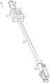
图1是根据一些实施例的示例器械推进装置的上部透视图;FIG. 1 is an upper perspective view of an example instrument advancement device in accordance with some embodiments;
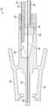
图2是根据一些实施例的器械推进装置的示例远侧端部的剖视图;FIG. 2 is a cross-sectional view of an example distal end of an instrument advancement device in accordance with some embodiments;
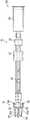
图3是根据一些实施例的器械推进装置的另一示例远侧端部的剖视图;3 is a cross-sectional view of another example distal end of an instrument advancement device in accordance with some embodiments;
图4是根据一些实施例的器械推进装置的示例壳体的剖视图,示出了延伸通过其中的示例延伸管;4 is a cross-sectional view of an example housing of an instrument advancement device showing an example extension tube extending therethrough, according to some embodiments;
图5A是根据一些实施例的器械推进装置的上部透视图,示出了处于缩回位置的示例壳体;5A is an upper perspective view of an instrument advancement device showing an example housing in a retracted position, according to some embodiments;
图5B是根据一些实施例的器械推进装置的上部透视图,示出了处于缩回位置的另一示例壳体;5B is an upper perspective view of an instrument advancement device showing another example housing in a retracted position, according to some embodiments;
图5C是根据一些实施例的器械推进装置的剖视图;5C is a cross-sectional view of an instrument advancement device according to some embodiments;
图6A是根据一些实施例的示例楔块的上部透视图;6A is an upper perspective view of an example wedge in accordance with some embodiments;
图6B是根据一些实施例的楔块的剖视图;6B is a cross-sectional view of a wedge in accordance with some embodiments;
图6C是根据一些实施例的楔块的另一上部透视图;Figure 6C is another top perspective view of a wedge in accordance with some embodiments;
图6D是根据一些实施例的示例支撑元件的上部透视图;6D is an upper perspective view of an example support element according to some embodiments;
图6E是根据一些实施例的支撑元件的近侧端部视图;Figure 6E is a proximal end view of a support element according to some embodiments;
图7是根据一些实施例的器械推进装置的剖视图,示出了多个支撑元件;7 is a cross-sectional view of an instrument advancement device showing a plurality of support elements, according to some embodiments;
图8A是根据一些实施例的器械推进装置的剖视图,示出了示例系索;8A is a cross-sectional view of an instrument advancement device showing an example lanyard, according to some embodiments;
图8B是根据一些实施例的支撑元件的上部透视图,示出了用于系索的示例开孔;8B is an upper perspective view of a support element showing an example aperture for a lanyard, according to some embodiments;
图8C是根据一些实施例的楔块的上部透视图,示出了用于系索的示例其它开孔;8C is an upper perspective view of a wedge block showing example other apertures for lanyards, according to some embodiments;
图9A是根据一些实施例的器械推进装置的剖视图,示出了示例可压缩元件;9A is a cross-sectional view of an instrument advancement device showing an example compressible element, according to some embodiments;
图9B是根据一些实施例的器械推进装置的剖视图,示出了可压缩元件;9B is a cross-sectional view of an instrument advancement device showing a compressible element, according to some embodiments;
图9C是根据一些实施例的器械推进装置的剖视图,示出了可压缩元件;9C is a cross-sectional view of an instrument advancement device showing a compressible element, according to some embodiments;
图9D是根据一些实施例的器械推进装置的剖视图,示出了可压缩元件和另一示例可压缩元件;9D is a cross-sectional view of an instrument advancement device showing a compressible element and another example compressible element, according to some embodiments;
图10是根据一些实施例的另一示例壳体的上部透视图;10 is an upper perspective view of another example housing in accordance with some embodiments;
图11是根据一些实施例的示例远侧连接器的上部透视图;11 is an upper perspective view of an example distal connector in accordance with some embodiments;
图12A是根据一些实施例的联接到示例导管组件的器械推进装置的上部透视图;12A is an upper perspective view of an instrument advancement device coupled to an example catheter assembly, according to some embodiments;
图12B是根据一些实施例的联接到另一示例导管组件的器械推进装置的上部透视图;12B is an upper perspective view of an instrument advancer coupled to another example catheter assembly, according to some embodiments;
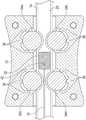
图13A是根据一些实施例的另一器械推进装置的横向剖视图;13A is a transverse cross-sectional view of another instrument advancement device in accordance with some embodiments;
图13B是根据一些实施例的另一器械推进装置的纵向剖视图。13B is a longitudinal cross-sectional view of another instrument advancement device in accordance with some embodiments.
具体实施方式Detailed ways
相关申请的交叉参考CROSS-REFERENCE TO RELATED APPLICATIONS
本申请要求第63/170,389号美国临时申请的优先权,所述申请的题目为“具有防屈曲特征的器械推进装置”,提交于2021年4月2日,所述申请的全部公开内容通过引用整体结合于此。This application claims priority to U.S. Provisional Application No. 63/170,389, entitled "Instrument Propulsion Device with Anti-buckling Features," filed April 2, 2021, the entire disclosure of which is incorporated by reference The whole is combined here.
现在参考图1-4,根据一些实施例,示出了器械推进装置10。在一些实施例中,器械推进装置10可以包括壳体12和延伸通过壳体12的延伸管14,在一些实施例中,延伸管14可以是刚性的、半刚性的或柔性的。在一些实施例中,延伸管14可以包括共同挤压的导丝,以为延伸管14增加刚度。在一些实施例中,延伸管14可以包括多内腔延伸管。在一些实施例中,延伸管14可以是透明的或不透明的。Referring now to Figures 1-4, an
在一些实施例中,器械推进装置10可以包括器械16,其可以包括导丝、器械、管或另一种合适的器械。在一些实施例中,器械16可以包括一个或多个传感器。在一些实施例中,器械16可以被着色以增加可见性。在一些实施例中,导丝可以由金属或另一种合适的材料构成。在这些和其它实施例中,器械16可以被润滑或涂覆以易于推进。在一些实施例中,作为管的器械可以是软的或硬的。在一些实施例中,管可以形成用于血液流动的闭合路径和/或减少由于导管组件中的药物吸附而导致的血液污染。In some embodiments, the
在一些实施例中,器械16可以包括导丝,所述导丝可以包括弹簧或线圈。在一些实施例中,弹簧或线圈可以包括沿着弹簧或线圈的长度的变化的节距。例如,导管末端上游或近侧的弹簧或线圈的节距可以更大,以便于更多的血液流动并增加流量,并且导管末端附近的弹簧或线圈的节距可以更小,以防止血凝块进入导管末端,同时仍然允许血液流过它。在一些实施例中,导丝可以包括杆,所述杆可以延伸通过弹簧或线圈的中心部分。在一些实施例中,导丝可以包括杆并且可以不包括弹簧或线圈。In some embodiments, the
随着时间的推移,导管可能由于纤维蛋白鞘、血栓或静脉壁或瓣膜的存在而在导管末端处变得阻塞。在一些实施例中,器械16可以构造成延伸进入和/或通过导管组件,以推动通过和/或破坏导管的阻塞。在一些实施例中,器械16可以克服导管组件中或周围或静脉中的血栓和纤维蛋白鞘,否则血栓和纤维蛋白鞘可能阻止输注或抽血。在一些实施例中,器械推进装置10可以减少对脉管系统的创伤,同时还有利于流体输送、血液采集、患者或装置监测或其它临床需要。在一些实施例中,器械推进装置10可以减少溶血并减少血液暴露。在一些实施例中,器械16可以包括脉管通路器械,其构造成向远侧推进通过导管组件并进入患者的脉管系统。Over time, the catheter may become blocked at the catheter tip due to the presence of a fibrin sheath, a thrombus, or the vein wall or valve. In some embodiments, the
在一些实施例中,器械推进装置10的远侧端部可以包括远侧连接器18或另一种合适的连接器。在一些实施例中,远侧连接器18可以构造为联接到导管组件,当远侧连接器18被联接时,所述导管组件可以存在于或已经驻留在患者的脉管系统内。在一些实施例中,导管组件可以包括导管适配器,所述导管适配器可以包括远侧端部、近侧端部和内腔,所述内腔延伸通过导管适配器的远侧端部和导管适配器的近侧端部。在一些实施例中,导管可以从导管适配器的远侧端部延伸。在一些实施例中,导管可以包括外周静脉内导管、中线导管或外周插入中心导管。在一些实施例中,导管组件可以包括引导针,所述引导针可以延伸通过导管并便于刺穿皮肤和脉管系统以将导管插入患者体内。在一些实施例中,在将器械推进装置10联接到导管组件之前,可以从导管组件移除引导针。In some embodiments, the distal end of the
在一些实施例中,导管组件可以是直截的(straight)。在其它实施例中,导管组件可以是集成的,具有与导管适配器集成的延伸管。在一些实施例中,导管组件可以包括延伸套件,所述延伸套件可以包括从导管适配器的侧端口延伸并且与所述侧端口集成的延伸管。在一些实施例中,远侧连接器18可以构造成联接到导管组件的一部分,诸如导管适配器的近侧端部和/或无针通路连接器。在一些实施例中,无针通路连接器可以联接到延伸套件的近侧端部、T形连接器或另一部分。在一些实施例中,无针通路连接器可以永久地连接到远侧连接器18,诸如像通过粘合剂,以防止使用者有意或无意地移除。In some embodiments, the catheter assembly may be straight. In other embodiments, the catheter assembly may be integrated, with an extension tube integrated with the catheter adapter. In some embodiments, the catheter assembly can include an extension kit that can include an extension tube extending from and integral with a side port of the catheter adapter. In some embodiments, the
在一些实施例中,延伸管14的远侧端部可以联接到远侧连接器18。在一些实施例中,延伸管14的近侧端部可以联接到近侧连接器20。在一些实施例中,器械16可以在输液或抽血之前或过程中推进。在一些实施例中,在完成抽血或输注之后并且在将器械推进装置10从导管组件脱离联接之前,使用者可以通过向后或向近侧移动壳体12来缩回器械16。因此,在一些实施例中,可以降低使用者暴露于血液的风险。In some embodiments, the distal end of
如图2所示,在一些实施例中,延伸管14可以包括第一内腔22和第二内腔24,所述第二内腔可以沿着延伸管14的整个长度与第一内腔22分开。在一些实施例中,血液采集路径可以延伸通过第一内腔22。在一些实施例中,器械16可以设置在第二内腔24内。在一些实施例中,第二内腔24的直径可以大于第一内腔22的直径。在一些实施例中,第一内腔22的直径和/或长度可以基于所需的流量和/或为了减少溶血来选择。在一些实施例中,不同的材料可以被共同挤压以形成第一内腔22和第二内腔24。在一些实施例中,第一内腔22和第二内腔24可以由不同的材料或相同的材料形成。As shown in FIG. 2 , in some embodiments, the
在一些实施例中,响应于沿着延伸管14向远侧移动壳体12,器械16可以在第二内腔24内向远侧推进。在一些实施例中,响应于沿着延伸管14向近侧移动壳体12,器械16可以在第二内腔24内向近侧缩回。In some embodiments, the
在一些实施例中,器械推进装置10可以包括隔膜26,所述隔膜设置在远侧连接器18内并且构造成密封第二内腔24或防止血液流入第二内腔24中。在这些和其它实施例中,隔膜26可以不密封第一内腔22,使得血液可以沿着流体路径28从远侧连接器18通过第一内腔22向近侧流动以用于血液采集。在一些实施例中,隔膜26可以为弹性体的。In some embodiments, the
在一些实施例中,当壳体12在近侧方向上完全缩回时,器械16的远侧端部可以设置在远侧连接器18的远侧端部的近侧。在一些实施例中,当壳体12在近侧方向上完全缩回时,器械16的远侧端部可以设置在隔膜26的近侧,和/或器械16可以密封在延伸管14内。In some embodiments, the distal end of the
在一些实施例中,器械推进装置10可以包括插管30,所述插管可以连接第一内腔22的远侧端部和远侧连接器18。在一些实施例中,插管30可以是钝的。在一些实施例中,流体路径28可以延伸通过插管30,这可以防止血液泄漏。在一些实施例中,插管30可以由钢、塑料、金属或另一种合适的材料构成。在一些实施例中,插管30可以联接到远侧连接器18或者与远侧连接器18整体形成为单个单元。在一些实施例中,隔膜26可以与第二内腔24同心,或者略微偏移,以获得足够的壁厚。In some embodiments, the
在一些实施例中,远侧连接器18可以包括轴38和两个杠杆臂40。在一些实施例中,两个杠杆臂40可以便于联接到无针通路连接器。在一些实施例中,轴38可以用润滑剂润滑,这可以减小插入导管组件中的力。在一些实施例中,凸形远侧连接器可以包括凸形鲁尔、凸形鲁尔锁、凸形滑动鲁尔、鲁尔或另一种合适的连接器。In some embodiments, the
如图3所示,在一些实施例中,隔膜26可以跨远侧连接器18的内腔的宽度延伸。在一些实施例中,隔膜26可以密封第二内腔24或防止血液流入第二内腔24中。在一些实施例中,插管30可以从第一内腔22延伸通过隔膜26,以允许流体从中流过。As shown in FIG. 3 , in some embodiments, the
如图4所示,在一些实施例中,器械推进装置10可以包括设置在壳体12和延伸管14的第二内腔24内的楔块32。在一些实施例中,器械推进装置10可以包括一对相对的夹捏构件34,其构造成夹捏(pinch)延伸管14。在一些实施例中,所述一对相对的夹捏构件34a、34b可以设置在壳体12内、在楔块32的近侧,并且构造成与壳体12一起沿着延伸管14移动。As shown in FIG. 4 , in some embodiments, the
在一些实施例中,器械16可以设置在第二内腔24内。在一些实施例中,响应于沿着延伸管14向远侧移动壳体12,所述一对相对的夹捏构件34a、34b可以向远侧推动楔块32,并且器械16可以向远侧推进。In some embodiments, the
在一些实施例中,器械推进装置10可以包括另一对相对的夹捏构件34c、34d,其构造成夹捏延伸管14。在一些实施例中,所述另一对相对的夹捏构件34c、34d可以设置在壳体内、在楔块32的远侧,并且构造成与壳体12一起沿着延伸管14移动。在一些实施例中,响应于沿着延伸管14向近侧移动壳体12,所述另一对相对的夹捏构件34c、34d可以向近侧推动楔块32,并且器械16可以向近侧缩回。In some embodiments, the
在本公开中,所述一对相对的夹捏构件34a、34b和所述另一对相对的夹捏构件34c、34d可以统称为“相对的夹捏构件34”。在一些实施例中,响应于壳体12沿着延伸管14的移动,相对的夹捏构件34可以相对于壳体12和延伸管14旋转,这可以旋转器械16并移动导管的远侧末端远离障碍物。在一些实施例中,壳体12的内表面可以包括与相对的夹捏构件34接触的一个或多个隆起36,这可以在相对的夹捏构件34旋转时减小摩擦。在一些实施例中,楔块32和/或相对的夹捏构件34可以用润滑剂润滑,这可以减少摩擦。In the present disclosure, the pair of opposing pinching
在一些实施例中,相对的夹捏构件34可以由塑料、金属或另一种合适的材料构成。在一些实施例中,相对的夹捏构件34可以包括可以构造成相对于壳体12转动的球形球、球支承、轮或圆柱体。在一些实施例中,相对的夹捏构件34可以包括轮,其可以是光滑的或包括沿着其边缘的脚。在这些实施例中,润滑剂可以被施加到轮的轴以减少摩擦。在一些实施例中,相对的夹捏构件34可以相对于壳体12固定。例如,相对的夹捏构件34可以模制到壳体12中。In some embodiments, opposing pinch members 34 may be constructed of plastic, metal, or another suitable material. In some embodiments, opposing pinch members 34 may comprise spherical balls, ball bearings, wheels, or cylinders that may be configured to rotate relative to
在一些实施例中,相对的夹捏构件34的数量可以基于楔块32的形状而变化。在一些实施例中,器械推进装置10可以包括响应于例如为圆柱形的楔块32的形状的一对相对的夹捏构件34a、34b和另一对相对的夹捏构件34c、34d。在一些实施例中,器械推进装置10可以包括响应于包括狗骨形状的楔块32的单对相对的夹捏构件34,诸如一对相对的夹捏构件34a、34b,并且所述单对可以设置在狗骨形状的中间或凹陷中。In some embodiments, the number of opposing pinch members 34 may vary based on the shape of the
在一些实施例中,楔块32可以包括弧形通道42,其可以为U形。在一些实施例中,弧形通道42的半径可以大致等于或匹配器械16的曲率半径。在一些实施例中,弧形通道42可以在楔块32内居中或偏离中心。在一些实施例中,器械16可以延伸并移动通过弧形通道42。在一些实施例中,器械16的第一端部44可以是固定的。在一些实施例中,器械16的第一端部44可以固定在延伸管14或远侧连接器18内。更详细地,在一些实施例中,器械16的第一端部44可以联接到延伸管14的内表面和/或远侧连接器18的内表面。在一些实施例中,第一端部44可以大致平行于器械16的第二端部46,所述第二端部可以是自由的。In some embodiments, the
在一些实施例中,响应于楔块32移动第一距离,器械16的第二端部46可以构造成向远侧推进第二距离。在一些实施例中,第二距离可以是第一距离的两倍。在一些实施例中,第二距离可以大于第一距离的两倍。在这些和其它实施例中,器械16可以延伸通过多个U形或其它弧形。In some embodiments, the
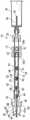
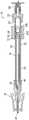
现在参考图5A-5C,在一些实施例中,器械16可能响应于楔块32向远侧推进而倾向于屈曲。在一些实施例中,支撑元件48可以设置在延伸管的内腔内,以减少器械16的屈曲。例如,支撑元件48可以设置在第二内腔24中。在一些实施例中,支撑元件48的位置可以改变。在一些实施例中,当壳体12处于缩回位置时,支撑元件48可以大致设置在楔块32和远侧连接器18的中间。因此,在一些实施例中,支撑元件48可以在器械16的易于屈曲的区域中提供支撑。Referring now to FIGS. 5A-5C, in some embodiments,
在一些实施例中,器械16可以延伸通过支撑元件48。在一些实施例中,支撑元件48可以包括第一孔50和第二孔52。在一些实施例中,器械16的第一端部44可以延伸通过第一孔50。在一些实施例中,器械16的第二端部46可以延伸通过第二孔52。In some embodiments, the
在一些实施例中,近侧连接器20可以联接到血液采集装置54。在一些实施例中,血液采集装置54可以包括注射器、BD


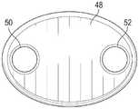
在一些实施例中,壳体12和/或近侧连接器20可以包括各种形状,这可以便于使用者抓握壳体12和/或近侧连接器20。例如,壳体12和/或近侧连接器20可以是椭圆形、圆形、正方形或另一种形状。在一些实施例中,如例如图5A-5B所示,近侧连接器20和/或远侧连接器18的形状可以通过提供握持位置以抵抗延伸管14的弯曲而使得使用者能够更容易地向近侧和/或向远侧滑动壳体12。在一些实施例中,壳体12的外表面和/或近侧连接器20的外表面可以包括一个或多个突起以便于握持。在一些实施例中,突起可以包括隆起、环或其它形状。In some embodiments,
在一些实施例中,楔块32可以包括各种形状。在一些实施例中,楔块32可以包括椭圆形形状,其具有比其可以在其中滑动的内腔的直径小的大直径和小直径。在一些实施例中,楔块32在弧形通道42处可以具有较小的大直径,这可以减小器械16和延伸管14之间的摩擦。在一些实施例中,楔块32可以在一侧或多侧上具有较大的大直径,以防止楔块32相对于延伸管14旋转。在一些实施例中,楔块32的长度可以大于楔块32在其中滑动的内腔的大直径,以防止楔块32旋转。In some embodiments, the
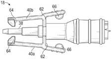
在一些实施例中,远侧连接器18可以包括轴38和设置在轴38的相对侧上的两个杠杆臂40a、40b。在一些实施例中,轴38可以包括钝插管,其可以是圆柱形的。在一些实施例中,两个杠杆臂40a、40b可以彼此相对,并且可以各自在弯曲点62处连接到远侧连接器18的主体。在一些实施例中,设置在两个杠杆臂40a、40b中的每一个的远侧端部处的钩构件64可以构造成当两个杠杆臂40a、40b处于松弛位置时设置在导管组件的凹槽内,如例如图5A-5C所示。在一些实施例中,凹槽可以是环形的。In some embodiments, the
在一些实施例中,两个杠杆臂40a、40b中的每一个的在弯曲点62的近侧的近侧端部可以被向内按压以向外偏置两个杠杆臂40a、40b中的每一个的远侧端部,并且从凹槽释放钩构件64。在一些实施例中,响应于两个杠杆臂40a、40b中的每一个的近侧端部被释放或未被向内按压,两个杠杆臂40a、40b中的每一个的远侧端部可以自动地从偏置位置返回到松弛位置。In some embodiments, the proximal end of each of the two
在一些实施例中,两个杠杆臂40a、40b中的每一个的近侧端部可以包括止动突起66,其可以防止将两个杠杆臂40a、40b按压得足够远以使两个杠杆臂40a、40b屈服或断裂。在一些实施例中,两个杠杆臂40a、40b中的每一个的止动突起66可以彼此相对地设置在近侧连接器20的主体上而代替在两个杠杆臂40a、40b上。在一些实施例中,止动突起66可以通过提供硬止挡而限制两个杠杆臂40a、40b能够被按压的距离。In some embodiments, the proximal end of each of the two
如图5A-5C所示,在一些实施例中,钝插管可以包括鲁尔形状,其可以包括鲁尔。在一些实施例中,鲁尔形状可以包括环形阶梯表面。在一些实施例中,鲁尔形状可以便于与诸如像BD Q-SYTETM无针连接器的装置密封,其均可以从New Jersey,Franklin Lakes的Becton&Dickinson获得。在一些实施例中,鲁尔形状可以减小BD SMARTSITETM无针连接器或BD Q-SYTETM(可以从New Jersey,Franklin Lakes的Becton&Dickinson获得)或类似装置的隔膜上的应力,并且防止隔膜响应于钝插管的移除而移位。As shown in Figures 5A-5C, in some embodiments, the blunt cannula may include a luer shape, which may include a luer. In some embodiments, the luer shape may include an annular stepped surface. In some embodiments, the luer shape may facilitate sealing with devices such as BD Q-SYTE™ needleless connectors, both available from Becton & Dickinson of Franklin Lakes, New Jersey. In some embodiments, the luer shape can reduce stress on the septum of a BD SMARTSITE™ needleless connector or BD Q-SYTE™ (available from Becton & Dickinson of Franklin Lakes, New Jersey) or similar devices and prevent the septum from responding Displacement due to removal of blunt cannula.
现在参考图6A-6C,根据一些实施例,示出了楔块32内的弧形通道42。现在参考图6D-6E,根据一些实施例,示出了支撑元件48。在一些实施例中,支撑元件48可以包括第一孔50和第二孔52,它们可以各自支撑延伸通过其中的器械16并防止器械16的屈曲。Referring now to FIGS. 6A-6C ,
现在参考图7,在一些实施例中,器械推进装置10可以包括一个或多个其它支撑元件68,其可以设置在延伸管14的内腔中,诸如像第二内腔24中。在一些实施例中,其它支撑元件68在一个或多个特征和/或操作方面可以与支撑元件48相似或相同。在一些实施例中,支撑元件48和支撑元件68可以在延伸管14内在楔块32的远侧均匀地间隔开。在一些实施例中,每个其它支撑元件68可以包括延伸通过其中的第一孔50和第二孔52。在一些实施例中,其它支撑元件68中的一个或多个可以具有不同的长度。在一些实施例中,支撑元件48和/或其它支撑元件68的第一孔50和/或第二孔52可以被润滑以减小摩擦并便于器械16通过其移动。Referring now to FIG. 7 , in some embodiments, the
在一些实施例中,当器械16向远侧推进和/或向近侧缩回时,支撑元件48和/或其它支撑元件68可以防止器械16的屈曲。在一些实施例中,支撑元件48和/或其它支撑元件68可以是圆柱形或椭圆形形状。在一些实施例中,支撑元件的长度和/或其它支撑元件68的长度可以大于设置在其中的内腔(例如第二内腔24)的内径,这可以防止支撑元件48和/或其它支撑元件68的旋转。在一些实施例中,第一孔50和/或第二孔52可以用从外边缘延伸的凹槽替换,所述凹槽可以支撑器械16。在一些实施例中,第一孔50和/或第二孔52可以是圆形、半圆形或另一种合适的形状。In some embodiments, the
在一些实施例中,支撑元件48和/或其它支撑元件68可以减小器械16的有效长度以增加根据以下等式的屈曲载荷:In some embodiments,

其中PE是临界屈曲载荷,E是杨氏模量,I是抵抗屈曲方向的惯性矩,并且L是器械16的长度。where PE is the critical buckling load,E is the Young's modulus, I is the moment of inertia against the buckling direction, and L is the length of the
现在参考图8A-8C,在一些实施例中,楔块32可以构造成响应于楔块32向远侧的移动而接触支撑元件48并使支撑元件48向远侧移动。在一些实施例中,楔块32可以接触并移动类似于支撑元件48的其它支撑元件68(参见例如图7)。Referring now to FIGS. 8A-8C , in some embodiments, the
在一些实施例中,器械推进装置10可以包括在楔块32和支撑元件48之间延伸的系索70。在一些实施例中,系索70可以固定到楔块32和支撑元件48,例如通过压配合、粘合剂、焊接或其它方式。在这些和其它实施例中,楔块32在近侧方向上的缩回也可以由于系索70的拉动而缩回支撑元件48。在一些实施例中,系索70可以是刚性的或柔性的。In some embodiments, the
在一些实施例中,支撑元件48可以包括延伸通过其中的开孔72。在一些实施例中,系索70可以延伸通过开孔72,并且楔块32可以构造成在不移动支撑元件48的情况下移动。在一些实施例中,楔块32可以包括延伸通过其中的另一开孔74,并且系索70可以延伸通过另一开孔74。在一些实施例中,开孔72可以在支撑元件48内居中或偏离中心。在一些实施例中,另一开孔74可以在楔块32内居中或偏离中心。在一些实施例中,用于器械16的第一孔50和/或第二孔52可以居中以适应用于系索70的开孔72和/或另一开孔74。在一些实施例中,用于器械16的第一孔50和/或第二孔52可以偏离中心以适应用于系索70的开孔72和/或另一开孔74。In some embodiments,
在一些实施例中,系索70的远侧端部可以在支撑元件48的远侧和/或可以包括捕获件76。在一些实施例中,系索70的近侧端部可以在楔块32的近侧端部和/或可以包括另一捕获件78。在一些实施例中,捕获件76的外径可以大于开孔72的直径和/或另一捕获件78的外径可以大于另一开孔74的外径。因此,在一些实施例中,响应于楔块32向近侧的移动,捕获件76可以接触支撑元件48的远侧端部,而另一捕获件78可以接触楔块32的近侧端部,以便在近侧方向上拉动支撑元件48。In some embodiments, the distal end of
现在参考图9A,在一些实施例中,器械推进装置10可以包括设置在延伸管14的内腔(诸如像第二内腔24)内、在楔块32的远侧的可压缩元件80。在一些实施例中,响应于楔块32向远侧的移动,楔块32可以构造成接触可压缩元件80以压缩可压缩元件80。在一些实施例中,可压缩元件80可以包括弹簧(如图9A所示)、伸缩装置、管或另一种可压缩元件。在一些实施例中,弹簧可以是圆形、椭圆形、正方形或另一种合适的形状。在一些实施例中,可压缩元件80可以在远侧-近侧和/或近侧-远侧方向上压缩。Referring now to FIG. 9A , in some embodiments, the
在一些实施例中,可压缩元件80的长度可以从楔块32或壳体12延伸到远侧连接器18。在一些实施例中,可压缩元件80可以在楔块32或壳体12与远侧连接器18之间部分地延伸,从而覆盖易于屈曲的点位。在一些实施例中,当壳体12处于缩回位置时,可压缩元件80可以大致设置在楔块32和远侧连接器18的中间,例如如图9A所示。因此,在一些实施例中,可压缩元件80可以在器械16的易于屈曲的区域中提供支撑。在一些实施例中,可压缩元件80可以包括弹簧,并且弹簧的弹簧常数可以足够弱,使得当弹簧被压缩时,弹簧不能克服在延伸管14与一对相对的夹捏构件34a、34b和/或另一对相对的夹捏构件34c、34d之间的法向力或摩擦力。因此,在一些实施例中,使用者可能不需要担心壳体12在近侧方向上弹回。In some embodiments, the length of the
在一些实施例中,可压缩元件80可以支撑器械16以减少屈曲。在一些实施例中,可压缩元件80可以设置在器械16的第一端部44和器械16的第二端部46之间。在一些实施例中,可压缩元件80可以同时支撑第一端部44和第二端部46以减少器械16的屈曲。In some embodiments, the
现在参考图9B,在一些实施例中,第一端部44可以延伸通过可压缩元件80,这可以防止第一端部44屈曲。现在参考图9C,第二端部46可以延伸通过可压缩元件80,这可以防止第二端部46屈曲。现在参考图9D,在一些实施例中,器械推进装置10可以包括设置在延伸管14的内腔(诸如像第二内腔24)内、在楔块32的远侧的另一可压缩元件82。在一些实施例中,另一可压缩元件82在一个或多个特征和/或操作方面可以与可压缩元件80相似或相同。在一些实施例中,器械16的第一端部44可以延伸通过可压缩元件80。在一些实施例中,器械16的第二端部46可以延伸通过另一可压缩元件82。Referring now to FIG. 9B, in some embodiments, the
现在参考图10,在一些实施例中,壳体84可以包括第一推动凸起86和/或第二推动凸起88。在一些实施例中,壳体84在一个或多个特征和/或操作方面可以与图1-9的壳体12相似或相同。在一些实施例中,第一推动凸起86和第二推动凸起88可以允许临床医生在不重新定位他或她的手的情况下在远侧方向上推进器械16。不然的话,壳体84可能需要在远侧方向上滑动得比平均的手尺寸能够在一次推动中滑动壳体84的距离更远,并且临床医生将重新定位他或她的手以继续在远侧方向上推动壳体84。在一些实施例中,为了将器械16从缩回位置推进到推进位置,临床医生可以重新定位他或她的手指,而非他或她的手握持,这是由于除了第一推动凸起86之外还有第二推动凸起88。在一些实施例中,壳体84可包括多于两个的推动凸起,其可以延伸壳体84的长度。Referring now to FIG. 10 , in some embodiments, the
在一些实施例中,第一推动凸起86可以在第二推动凸起88的远侧和/或壳体84的远侧端部处。在一些实施例中,第二推动凸起88可以在壳体84的近侧端部处。在一些实施例中,第一推动凸起86和第二推动凸起88可以具有相同的高度,这可以有利于临床医生的手指的固定。在一些实施例中,第一推动凸起86和第二推动凸起88可以具有不同的高度。例如,第一推动凸起86可以比第二推动凸起88高,如果手指不能配合在第一推动凸起86和第二推动凸起88之间,这可以使壳体84的上表面更容易推动。在一些实施例中,壳体84可以包括延伸通过其中并且构造成接收延伸管14的开口90。在一些实施例中,第一推动凸起86和第二推动凸起88可以便于临床医生单手推进器械16。In some embodiments, the
现在参考图11,根据一些实施例,示出了远侧连接器18。在一些实施例中,两个杠杆臂40a、40b中的每一个的近侧端部可以包括止动突起66,其可以防止将两个杠杆臂40a、40b按压得足够远以使两个杠杆臂40a、40b屈服或断裂。在一些实施例中,两个杠杆臂40a、40b可以彼此相对并且可以各自在弯曲点62处连接到远侧连接器18的主体。在一些实施例中,设置在两个杠杆臂40a、40b中的每一个的远侧端部处的钩构件64可以构造成扣在导管组件的一部分上。在一些实施例中,两个杠杆臂40a、40b中的每一个的止动突起66可以彼此相对地设置在远端连接器18的主体上而代替在两个杠杆臂40a、40b上。Referring now to FIG. 11 , according to some embodiments, a
现在参考图12A,在一些实施例中,导管组件92可以包括导管适配器94和从导管适配器94的远侧端部向远侧延伸的导管96。在一些实施例中,导管适配器94可以包括侧端口99,并且导管组件92可以包括从侧端口99延伸的延伸管100。在一些实施例中,导管组件92可以包括连接器102(诸如像T形连接器),其可以联接到延伸管100的近侧端部和延伸管104。在一些实施例中,导管组件92可以包括无针通路连接器106,其可以联接到连接器102的近侧端部和远侧连接器18。在这些和其它实施例中,导管组件92可以被称为集成的,具有与侧端口99集成的延伸管100。在一些实施例中,器械16将响应于特定壳体在远侧方向上的推进而插入通过侧端口99和导管96。Referring now to FIG. 12A , in some embodiments, the
现在参考图12B,在一些实施例中,导管组件100可以包括连接器102(诸如像T形连接器)以及联接到连接器102的延伸管104。在一些实施例中,导管组件108可以包括联接到连接器102和器械推进装置10的无针通路连接器106。在一些实施例中,连接器102可以联接到导管组件100的导管适配器110的近侧端部。在一些实施例中,导管组件100可以包括从导管适配器110的远侧端部向远侧延伸的导管112。在这些和其它实施例中,导管组件108可以被称为直截的。在一些实施例中,器械16将响应于特定壳体在远侧方向上的推进而插入通过导管适配器110的近侧端部和导管96。Referring now to FIG. 12B , in some embodiments, the
现在参考图13A-13B,根据一些实施例,示出了器械推进装置119。在一些实施例中,器械推进装置119在一个或多个特征和/或操作方面可以与图1-12中的一个或多个的器械推进装置10相似或相同。在一些实施例中,楔块32可以包括凹陷或凹穴120。在一些实施例中,凹穴120可以设置在弧形通道42的内部。在一些实施例中,楔块32可以设置在延伸管14的内腔内,所述内腔可以包括第二内腔24。Referring now to Figures 13A-13B, an
在一些实施例中,器械推进装置119可以包括延伸通过弧形通道42的器械16。在一些实施例中,器械16可以改善导管组件的导管的通畅性,以用于通过导管的留置时间进行药物和流体输送以及血液采集。在一些实施例中,当器械推进装置119联接到导管组件时,导管可以留置或插入患者的脉管系统中。在一些实施例中,器械推进装置119可以有利于血液采集期间的血液流动和质量,改善工作流程,并且降低操纵相关导管并发症的风险。In some embodiments, the
在一些实施例中,第二端部46可以包括杆、线圈或构造成促进血栓移除和/或减少对脉管系统的损伤的任何其它合适的形状。在一些实施例中,线圈可以围绕杆。在一些实施例中,第二端部46的最远侧部分可以是钝的,以降低损伤脉管系统的风险。在一些实施例中,第二端部46可以是多孔的,以便于血液流过。在一些实施例中,第一端部44可以固定在延伸管14内部。例如,第一端部44可以粘附、粘接或以另一种适当的方式固定在延伸管14内。In some embodiments, the
在一些实施例中,第二端部46可以构造成响应于壳体12向远侧移动第二距离而向远侧推进第一距离。在一些实施例中,第一距离可以是第二距离的至少两倍。在一些实施例中,可以在不使器械16与壳体12接触的情况下促进器械16的移动,这可以降低器械16的细菌污染的风险。In some embodiments, the
在一些实施例中,器械推进装置119可以包括设置在壳体12和延伸管14的外表面之间并且在凹穴120内的平移特征122,使得响应于壳体12沿着延伸管14的外表面向远侧移动第一距离,楔块32可以在内腔18内向远侧移动第一距离,并且器械16的第二端部46可以向远侧推进第二距离。在一些实施例中,平移特征122可以包括球、轮、滚子支承或构造成产生延伸管14的局部压缩的另一种合适的特征。在一些实施例中,平移特征122可以是壳体12的一部分和/或与壳体12整体地形成为单个单元。In some embodiments, the
在一些实施例中,延伸管14可以由柔性材料构成,诸如热塑性弹性体(TPE)、热塑性聚氨酯(TPU)、
在一些实施例中,平移特征122可以压缩延伸管14,使得延伸管14延伸到凹穴120中。在一些实施例中,将延伸管14压缩到凹穴120中的平移特征122可以便于楔块32与壳体12一起移动。In some embodiments, the translating
在一些实施例中,器械推进装置119可以包括一个或多个附加平移特征124。在一些实施例中,附加平移特征124可以设置在壳体12的与平移特征122相对的一侧上,并且设置在延伸管14和壳体12之间。在一些实施例中,平移特征122和/或附加平移特征124可以防止延伸管14接触壳体12,从而允许壳体12以减小的摩擦沿着延伸管14的纵向轴线移动。在一些实施例中,附加平移特征124可以各自包括滚珠、轮、支承或另一种合适的特征。In some embodiments, the
在一些实施例中,平移特征122和/或附加平移特征124可以设置在壳体12中的凹陷126内。在一些实施例中,凹陷126中的一个或多个的表面可以包括一个或多个小突起128,其可以减小壳体12与平移特征122和/或附加平移特征124接触的表面区域的尺寸。在一些实施例中,凹陷126可以被成形为大致类似于平移特征122和/或附加平移特征124,其可以是球形的。在一些实施例中,楔块32的与凹穴120相对的表面可以包括一个或多个隆起130,其可以减小楔块32与壳体12接触的表面区域的尺寸,并允许楔块32以减小的摩擦相对于延伸管14移动。在一些实施例中,楔块32可以是大致三角形或三点形(three-point)。In some embodiments, translating
在一些实施例中,延伸管14可以包括第一内腔22。在一些实施例中,第一内腔22可以延伸通过延伸管14的远侧端部13和延伸管14的近侧端部17,并且可以构造成用于流体从中流过。在一些实施例中,第一内腔22的宽度和/或长度可以构造成提供减少血液采集时间同时还减少血液采集期间的溶血的血液流量。在一些实施例中,响应于壳体12的1x推进的器械16的2x或大于2x的推进可以使得用于血液采集的延伸管14和第一内腔22能够更短,从而导致第一内腔22中的血液体积更少。In some embodiments,
在一些实施例中,器具推进装置119可以包括隔膜26,所述隔膜可以设置在远侧连接器18或延伸管14的远侧端部内。在一些实施例中,器械16可以构造成延伸通过隔膜26。在一些实施例中,隔膜26可以被定位成允许远侧流体流入第一内腔22,但可以阻止远侧流体流入第二内腔24。在一些实施例中,第二内腔24的近侧端部可以被封闭。例如,隔膜或密封件可以设置在第二内腔24的近侧端部内,或者可以由延伸管14封闭。在一些实施例中,第二内腔24可以大于第一内腔22。在一些实施例中,第一内腔22可以沿着延伸管14在中心延伸。In some embodiments, the
在一些实施例中,器械16可以完全容纳在第二内腔24内。更详细地,在一些实施例中,当器械16处于完全缩回位置和/或壳体12处于近侧位置时,器械16的第二端部46可以设置在隔膜26的近侧。在其它实施例中,当器械16处于完全缩回位置和/或壳体12处于近侧位置时,器械16可以延伸通过隔膜26,但第二端部46可以设置在远侧连接器18内。In some embodiments, the
在一些实施例中,器械推进装置119可以包括图5C的支撑元件48和/或图7的其它支撑元件68。在一些实施例中,器械推进装置119可以包括图8A的系索70和/或图9A-9D的可压缩元件80。在一些实施例中,系索70可以包括模制塑料。在一些实施例中,器械推进装置119可以包括图9D的另一可压缩元件82。In some embodiments, the
本文叙述的所有示例和条件语言旨在教导目的,以帮助读者理解本实用新型和发明人为了促进本领域而贡献的概念,并且应当被解释为不限于这样具体叙述的示例和条件。尽管已经详细描述了本实用新型的实施例,但是应当理解,在不脱离本实用新型的精神和范围的情况下,可以对其进行各种改变、替换和变更。All examples and conditional language recited herein are intended for educational purposes to assist the reader in understanding the invention and the concepts contributed by the inventors to advance the art, and should be construed as not limited to such specifically recited examples and conditions. Although the embodiments of the present invention have been described in detail, it should be understood that the various changes, substitutions, and alterations could be made hereto without departing from the spirit and scope of the invention.
Claims (20)
Applications Claiming Priority (2)
| Application Number | Priority Date | Filing Date | Title |
|---|---|---|---|
| US202163170389P | 2021-04-02 | 2021-04-02 | |
| US63/170,389 | 2021-04-02 |
Publications (1)
| Publication Number | Publication Date |
|---|---|
| CN217447802Utrue CN217447802U (en) | 2022-09-20 |
Family
ID=83268701
Family Applications (2)
| Application Number | Title | Priority Date | Filing Date |
|---|---|---|---|
| CN202210349576.3APendingCN115192017A (en) | 2021-04-02 | 2022-04-02 | Instrument propulsion device with anti-buckling feature |
| CN202220769035.1UActiveCN217447802U (en) | 2021-04-02 | 2022-04-02 | Instrument propulsion device |
Family Applications Before (1)
| Application Number | Title | Priority Date | Filing Date |
|---|---|---|---|
| CN202210349576.3APendingCN115192017A (en) | 2021-04-02 | 2022-04-02 | Instrument propulsion device with anti-buckling feature |
Country Status (10)
| Country | Link |
|---|---|
| US (1) | US12434041B2 (en) |
| EP (1) | EP4312842A4 (en) |
| JP (1) | JP2024512759A (en) |
| KR (1) | KR20230166116A (en) |
| CN (2) | CN115192017A (en) |
| AU (1) | AU2022249086A1 (en) |
| BR (1) | BR112023020063A2 (en) |
| CA (1) | CA3214063A1 (en) |
| MX (1) | MX2023011677A (en) |
| WO (1) | WO2022212649A1 (en) |
Families Citing this family (1)
| Publication number | Priority date | Publication date | Assignee | Title |
|---|---|---|---|---|
| WO2025162317A1 (en)* | 2024-02-03 | 2025-08-07 | 杭州大士科技有限公司 | Interventional consumable delivery mechanism with acceleration sensing and method for sensing circumferential torque and axial force |
Family Cites Families (10)
| Publication number | Priority date | Publication date | Assignee | Title |
|---|---|---|---|---|
| US6929481B1 (en)* | 1996-09-04 | 2005-08-16 | Immersion Medical, Inc. | Interface device and method for interfacing instruments to medical procedure simulation systems |
| US9668690B1 (en) | 2001-05-01 | 2017-06-06 | Intrapace, Inc. | Submucosal gastric implant device and method |
| US7699809B2 (en)* | 2006-12-14 | 2010-04-20 | Urmey William F | Catheter positioning system |
| US8585713B2 (en) | 2007-10-17 | 2013-11-19 | Covidien Lp | Expandable tip assembly for thrombus management |
| US11273290B2 (en)* | 2014-09-10 | 2022-03-15 | Intuitive Surgical Operations, Inc. | Flexible instrument with nested conduits |
| US10179046B2 (en)* | 2015-08-14 | 2019-01-15 | Edwards Lifesciences Corporation | Gripping and pushing device for medical instrument |
| US10773056B2 (en)* | 2017-03-21 | 2020-09-15 | Velano Vascular, Inc. | Systems and methods for controlling catheter device size |
| KR102573751B1 (en) | 2017-03-21 | 2023-09-04 | 벨라노 바스큘라, 인크. | Devices and methods for fluid delivery through a deployed peripheral intravenous catheter |
| US20180333560A1 (en)* | 2017-05-18 | 2018-11-22 | Cook Medical Technologies Llc | System for controlled deployment of medical devices |
| EP4363025A4 (en) | 2021-07-02 | 2025-07-16 | Becton Dickinson Co | Vascular access device to reduce probe kinking |
- 2022
- 2022-03-31JPJP2023560796Apatent/JP2024512759A/enactivePending
- 2022-03-31EPEP22782175.8Apatent/EP4312842A4/enactivePending
- 2022-03-31USUS17/709,980patent/US12434041B2/enactiveActive
- 2022-03-31AUAU2022249086Apatent/AU2022249086A1/enactivePending
- 2022-03-31CACA3214063Apatent/CA3214063A1/enactivePending
- 2022-03-31KRKR1020237037732Apatent/KR20230166116A/enactivePending
- 2022-03-31BRBR112023020063Apatent/BR112023020063A2/enunknown
- 2022-03-31MXMX2023011677Apatent/MX2023011677A/enunknown
- 2022-03-31WOPCT/US2022/022752patent/WO2022212649A1/ennot_activeCeased
- 2022-04-02CNCN202210349576.3Apatent/CN115192017A/enactivePending
- 2022-04-02CNCN202220769035.1Upatent/CN217447802U/enactiveActive
Also Published As
| Publication number | Publication date |
|---|---|
| BR112023020063A2 (en) | 2023-11-14 |
| AU2022249086A1 (en) | 2023-10-26 |
| CN115192017A (en) | 2022-10-18 |
| MX2023011677A (en) | 2023-10-18 |
| WO2022212649A1 (en) | 2022-10-06 |
| EP4312842A4 (en) | 2025-06-11 |
| US20220323737A1 (en) | 2022-10-13 |
| EP4312842A1 (en) | 2024-02-07 |
| US12434041B2 (en) | 2025-10-07 |
| CA3214063A1 (en) | 2022-10-06 |
| JP2024512759A (en) | 2024-03-19 |
| KR20230166116A (en) | 2023-12-06 |
Similar Documents
| Publication | Publication Date | Title |
|---|---|---|
| KR102664621B1 (en) | Mechanism delivery device with rotating element | |
| CN215916114U (en) | Extension set | |
| CN217067263U (en) | Vascular access instrument propulsion device | |
| CN218784432U (en) | Instrument propulsion | |
| CN218900531U (en) | Vascular access device | |
| US20220379087A1 (en) | Catheter Extension Set Having a Patency or Monitoring Instrument | |
| CN217447802U (en) | Instrument propulsion device | |
| CN218458132U (en) | Instrument propulsion | |
| US20220313958A1 (en) | Instrument Delivery Devices, Systems, and Methods |
Legal Events
| Date | Code | Title | Description |
|---|---|---|---|
| GR01 | Patent grant | ||
| GR01 | Patent grant |