CN217441281U - Electronic equipment support with storage base - Google Patents
Electronic equipment support with storage baseDownload PDFInfo
- Publication number
- CN217441281U CN217441281UCN202221158914.7UCN202221158914UCN217441281UCN 217441281 UCN217441281 UCN 217441281UCN 202221158914 UCN202221158914 UCN 202221158914UCN 217441281 UCN217441281 UCN 217441281U
- Authority
- CN
- China
- Prior art keywords
- storage
- storage base
- slot
- electronic device
- fixing
- Prior art date
- Legal status (The legal status is an assumption and is not a legal conclusion. Google has not performed a legal analysis and makes no representation as to the accuracy of the status listed.)
- Expired - Fee Related
Links
Images

Landscapes
- Casings For Electric Apparatus (AREA)
Abstract
Description
Translated fromChinese技术领域technical field
本实用新型涉及涉及一种带收纳底座的电子设备支架。The utility model relates to an electronic equipment bracket with a storage base.
背景技术Background technique
随着用户每天使用手机、电子阅读器、平板电脑等电子设备的时间日益增长,用于放置电子设备的电子设备支架也受到越来越多用户的青睐。电子设备支架能够解放双手,使得用户使用电子设备更加便利,但是现有的电子设备支架大多仅用于固定电子设备,不具备收纳功能,功能单一。As users spend more and more time using electronic devices such as mobile phones, e-readers, and tablet computers every day, electronic device brackets for placing electronic devices are also favored by more and more users. The electronic device bracket can free the hands and make it more convenient for the user to use the electronic device. However, most of the existing electronic device brackets are only used to fix the electronic device, have no storage function, and have a single function.
实用新型内容Utility model content
本实用新型要解决的技术问题在于,针对现有技术的上述缺陷,提供一种带收纳底座的电子设备支架。The technical problem to be solved by the present invention is to provide an electronic equipment bracket with a storage base in view of the above-mentioned defects of the prior art.
本实用新型解决其技术问题所采用的技术方案是:一种带收纳底座的电子设备支架,包括立管;所述立管的一端通过第一固定组件连接有用于收纳物品的收纳底座,另一端通过第二固定组件转动连接有连接臂;所述连接臂上安装有用于固定电子设备的夹持组件;所述第一固定组件、所述第二固定组件均与所述立管可拆卸连接;The technical solution adopted by the utility model to solve the technical problem is as follows: an electronic equipment bracket with a storage base, comprising a riser; one end of the riser is connected with a storage base for storing articles through a first fixing component, and the other end is connected with a storage base for storing articles. A connecting arm is rotatably connected through the second fixing component; a clamping component for fixing electronic equipment is installed on the connecting arm; the first fixing component and the second fixing component are detachably connected to the riser;
本实用新型所述的带收纳底座的电子设备支架,其中,所述第一固定组件包括与所述收纳底座一体连接的第一固定块;所述第一固定块上设有供所述立管放置的第一通槽,和供第一插接件放置的第二通槽;所述第一通槽与所述第二通槽贯通连接;所述立管靠近所述第一固定组件的一端设有供所述第一插接件插入的第一通孔;The electronic equipment bracket with a storage base according to the present invention, wherein the first fixing component includes a first fixing block integrally connected with the storage base; the first fixing block is provided with the riser pipe a first through groove for placement, and a second through groove for placing the first plug; the first through groove is connected to the second through groove through; the riser is close to one end of the first fixing component a first through hole into which the first plug is inserted;
本实用新型所述的带收纳底座的电子设备支架,其中,所述第二固定组件包括与所述立管转动连接的第二固定块;所述第二固定块内设有供轴承及第二插接件放置的第三通槽,供所述立管放置的第四通槽,和供所述连接臂插入的第五通槽;所述第四通槽与所述第五通槽均与所述第三通槽贯通连接;所述轴承与所述连接臂上均设有供所述第二插接件插入的第二通孔;所述轴承的一端与所述第二插接件固定连接,另一端与所述立管固定连接;In the electronic equipment bracket with a storage base according to the present invention, wherein the second fixing component includes a second fixing block rotatably connected with the standpipe; the second fixing block is provided with a bearing and a second fixing block. The third through slot for placing the plug connector, the fourth through slot for the riser to be placed, and the fifth through slot for the connecting arm to be inserted into; the fourth through slot and the fifth through slot are the same as the The third through groove is connected through; the bearing and the connecting arm are both provided with a second through hole for inserting the second plug; one end of the bearing is fixed to the second plug connected, and the other end is fixedly connected with the riser;
本实用新型所述的带收纳底座的电子设备支架,其中,所述收纳底座包括底座本体;所述底座本体上设有收纳槽,和与所述收纳槽适配的抽屉;所述抽屉沿所述收纳槽与所述底座本体滑动连接;The electronic equipment support with a storage base according to the present utility model, wherein the storage base comprises a base body; the base body is provided with a storage slot and a drawer adapted to the storage slot; the drawer is arranged along the the receiving groove is slidably connected with the base body;
本实用新型所述的带收纳底座的电子设备支架,其中,所述收纳底座上可拆卸安装有至少一个收纳盒;一个或多个所述收纳盒堆叠设置于所述收纳底座上;The electronic equipment bracket with a storage base according to the present utility model, wherein, at least one storage box is detachably installed on the storage base; one or more of the storage boxes are stacked on the storage base;
本实用新型所述的带收纳底座的电子设备支架,其中,所述收纳底座的下表面与所述收纳盒的下表面均固设有连接板;所述收纳底座的上表面与所述收纳盒的上表面均固设有固定所述连接板的定位环;堆叠时,所述连接板套设于所述定位环内;The electronic equipment bracket with a storage base according to the present utility model, wherein the lower surface of the storage base and the lower surface of the storage box are fixed with connecting plates; the upper surface of the storage base and the storage box are fixed with connecting plates; A positioning ring for fixing the connecting plate is fixed on the upper surface of the connecting plate; when stacking, the connecting plate is sleeved in the positioning ring;
本实用新型所述的带收纳底座的电子设备支架,其中,所述收纳底座的上表面和所述收纳盒的上表面的边缘均为向内凹的弧面,中部均为与所述弧面连接的平面;所述弧面、所述平面和所述定位环形成可容纳所述连接板的容纳槽;In the electronic equipment bracket with a storage base according to the present invention, the upper surface of the storage base and the edge of the upper surface of the storage box are both inwardly concave arc surfaces, and the middle parts are both concave arc surfaces. a connecting plane; the arc surface, the plane and the positioning ring form an accommodating groove for accommodating the connecting plate;
本实用新型所述的带收纳底座的电子设备支架,其中,所述收纳底座内还设有配重块;In the electronic equipment support with a storage base according to the utility model, a counterweight block is further arranged in the storage base;
本实用新型所述的带收纳底座的电子设备支架,其中,所述连接板的面积小于所述收纳底座下表面的面积;The electronic equipment bracket with a storage base according to the present invention, wherein the area of the connecting plate is smaller than the area of the lower surface of the storage base;
本实用新型所述的带收纳底座的电子设备支架,其中,所述连接板的底部还设有防滑垫。In the electronic equipment bracket with a storage base according to the utility model, a non-slip pad is also provided at the bottom of the connecting plate.
本实用新型的有益效果在于:该带收纳底座的电子设备支架结构简单,立管的一端通过第一固定组件连接有用于收纳物品的收纳底座,另一端通过第二固定组件转动连接有连接臂;连接臂上安装有用于固定电子设备的夹持组件,以上结构不仅可以实现对电子设备的夹持固定,而且还可以实现对电子设备的数据线、充电器或其他物品的收纳,整体外观美观,功能多样,同时,采用可收纳的底座之后,使得该电子设备支架的空间利用率更大,布局合理,大大节省了空间,且更加方便用户的使用,实用性强。The beneficial effect of the utility model is that the electronic equipment bracket with the storage base has a simple structure, one end of the riser is connected with a storage base for storing articles through the first fixing component, and the other end is connected with a connecting arm through the second fixing component in rotation; The connecting arm is equipped with a clamping component for fixing the electronic device. The above structure can not only realize the clamping and fixing of the electronic device, but also realize the storage of the data cable, charger or other items of the electronic device. The overall appearance is beautiful, The utility model has various functions. At the same time, after adopting a stowable base, the space utilization rate of the electronic equipment bracket is larger, the layout is reasonable, the space is greatly saved, and the use is more convenient for users and has strong practicability.
附图说明Description of drawings
为了更清楚地说明本发明实施例或现有技术中的技术方案,下面将结合附图及实施例对本实用新型作进一步说明,下面描述中的附图仅仅是本发明的部分实施例,对于本领域普通技术人员来讲,在不付出创造性劳动的前提下,还可以根据这些附图获得其他附图:In order to more clearly illustrate the embodiments of the present invention or the technical solutions in the prior art, the present invention will be further described below with reference to the accompanying drawings and embodiments. The accompanying drawings in the following description are only some embodiments of the present invention. For those of ordinary skill in the art, other drawings can also be obtained from these drawings without any creative effort:
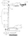
图1是本实用新型较佳实施例的一种带收纳底座的电子设备支架的结构示意图;1 is a schematic structural diagram of an electronic equipment bracket with a storage base according to a preferred embodiment of the present invention;
图2是本实用新型较佳实施例的一种带收纳底座的电子设备支架的爆炸图。FIG. 2 is an exploded view of an electronic equipment bracket with a storage base according to a preferred embodiment of the present invention.
具体实施方式Detailed ways
为了使本实用新型实施例的目的、技术方案和优点更加清楚,下面将结合本实用新型实施例中的技术方案进行清楚、完整的描述,显然,所描述的实施例是本实用新型的部分实施例,而不是全部实施例。基于本发明的实施例,本领域普通技术人员在没有付出创造性劳动的前提下所获得的所有其他实施例,都属于本实用新型的保护范围。In order to make the purposes, technical solutions and advantages of the embodiments of the present utility model clearer, the following will be a clear and complete description of the technical solutions in the embodiments of the present utility model. Obviously, the described embodiments are part of the implementation of the present utility model. examples, but not all examples. Based on the embodiments of the present invention, all other embodiments obtained by those of ordinary skill in the art without creative work fall within the protection scope of the present invention.
本实用新型较佳实施例的一种带收纳底座的电子设备支架,如图1-2所示,包括立管11;立管11的一端通过第一固定组件12连接有用于收纳物品的收纳底座13,另一端通过第二固定组件14转动连接有连接臂15;连接臂15上安装有用于固定电子设备(图中未示)的夹持组件16;第一固定组件12、第二固定组件14均与立管11可拆卸连接。A preferred embodiment of the present invention is an electronic equipment bracket with a storage base, as shown in Figures 1-2, comprising a
值得说明的是,电子设备包括但不限于平板电脑、手机等。It is worth noting that electronic devices include but are not limited to tablet computers, mobile phones, and the like.
该带收纳底座的电子设备支架结构简单,立管的一端通过第一固定组件连接有用于收纳物品的收纳底座,另一端通过第二固定组件转动连接有连接臂;连接臂上安装有用于固定电子设备的夹持组件,以上结构不仅可以实现对电子设备的夹持固定,而且还可以实现对电子设备的数据线、充电器或其他物品的收纳,整体外观美观,功能多样,同时,采用可收纳的底座之后,使得该电子设备支架的空间利用率更大,布局合理,大大节省了空间,且更加方便用户的使用,实用性强。The electronic equipment bracket with a storage base has a simple structure. One end of the riser is connected with a storage base for storing items through a first fixing component, and the other end is connected with a connecting arm through a second fixing component. The clamping component of the device, the above structure can not only realize the clamping and fixing of the electronic device, but also realize the storage of the data cable, charger or other items of the electronic device. The overall appearance is beautiful and the functions are various. After the base is formed, the space utilization rate of the electronic equipment bracket is larger, the layout is reasonable, the space is greatly saved, the use of the electronic equipment is more convenient for users, and the practicability is strong.
具体地,第一固定组件12包括与收纳底座13一体连接的第一固定块121;第一固定块121上设有供立管11放置的第一通槽122,和供第一插接件123放置的第二通槽124;第一通槽122与第二通槽124贯通连接;第一通槽122与第二通槽124相互垂直;立管11靠近第一固定组件12的一端设有供第一插接件123插入的第一通孔125;安装时,将立管从第一固定块上的第一通槽中插入,然后将插接件从第二通槽中插入,直到其端部插入立管上的第一通孔中,将立管固定在第一固定块上,安装方便;拆卸时,只需将插接件拔出,即可将立管与收纳底座分开,便于携带。Specifically, the
具体地,第二固定组件14包括与立管11转动连接的第二固定块141;第二固定块141内设有供轴承142及第二插接件143放置的第三通槽144,供立管11放置的第四通槽145,和供连接臂15插入的第五通槽146;第四通槽145与第三通槽144相互平行且同轴心设置;第五通槽146与第三通槽144垂直设置;第四通槽145与第五通槽146均与第三通槽144贯通连接;轴承142与连接臂15上均设有供第二插接件143插入的第二通孔147;连接臂15位于轴承142的上方;轴承142的一端与第二插接件143固定连接,另一端与立管11固定连接;安装时,将连接臂从第五通槽插入并延伸进第三通槽内,立管插入第四通槽内;第二插接件从第三通槽中插入,穿过连接臂与轴承固定连接;用手带动连接臂转动时,第二固定块也随之转动。Specifically, the
具体地,收纳底座13包括底座本体131;底座本体131上设有收纳槽(图中未示),和与收纳槽132适配的抽屉132;抽屉132沿收纳槽(图中未示)与底座本体131滑动连接,空间利用率大,外观美观。Specifically, the
值得说明的是,收纳底座13内还设有防止电子设备支架倾斜的配重块135,稳定性强,使得带收纳底座的电子设备支架不容易发生倾斜。It is worth noting that the
具体地,收纳底座13上可拆卸安装有至少一个收纳盒14;一个或多个收纳盒14堆叠设置于收纳底座13上,加大空间利用率,结构稳定。Specifically, at least one
具体地,收纳底座13的下表面与收纳盒14的下表面均固设有连接板133;收纳底座13的上表面与收纳盒14的上表面均固设有与固定连接板133的定位环134;堆叠时,连接板133套设于定位环134内,连接板133的面积小于收纳底座13下表面的面积,拆卸方便。Specifically, the lower surface of the
具体地,收纳底座13的上表面和收纳盒14的上表面的边缘均为向内凹的弧面136,中部均为与弧面连接的平面137;该弧面、平面和定位环形成可容纳连接板133的容纳槽;方便收纳盒依次堆叠在收纳底座上,整齐美观。Specifically, the edges of the upper surface of the
具体地,连接板133的底部还设有防滑垫(图中未示),稳定性更好。Specifically, the bottom of the connecting
具体地,立管11为伸缩管,其包括外管111和与外管111滑动连接的内管112;该内管可以有多个,多个内管依次套接;外管111套于内管112外,且内管112至少有一部分突出于外管111外侧;内管112的外侧表面沿其长度方向设有向内凹的导向滑槽113;外管111上设有向内凸起的凹槽114;凹槽114的凸起与导向滑槽113相适配;凹槽114与导向滑槽113过盈连接,通过上下拉动外管与内管,可以调节夹持组件的高度,灵活度高。Specifically, the
具体地,夹持组件16包括供电子设备放置的面板161;面板161的一端设有第一夹臂162和带动第一夹臂162靠近面板161的第一弹性件163,另一端设有第二夹臂164和带动第二夹臂164靠近面板161的第二弹性件165;第一夹臂162与第二夹臂164相对运动,通过拉动第一夹臂与第二夹臂的距离,可以夹持不同尺寸的电子设备,实用性强。值得说明的是,该夹持组件并不限于图中所示的结构,还可以是现有技术可以用于固定电子设备的其他结构。Specifically, the
应当理解的是,对本领域普通技术人员来说,可以根据上述说明加以改进或变换,而所有这些改进和变换都应属于本实用新型所附权利要求的保护范围。It should be understood that, for those skilled in the art, improvements or transformations can be made according to the above description, and all these improvements and transformations should belong to the protection scope of the appended claims of the present invention.
Claims (10)
Translated fromChinesePriority Applications (1)
| Application Number | Priority Date | Filing Date | Title |
|---|---|---|---|
| CN202221158914.7UCN217441281U (en) | 2022-05-13 | 2022-05-13 | Electronic equipment support with storage base |
Applications Claiming Priority (1)
| Application Number | Priority Date | Filing Date | Title |
|---|---|---|---|
| CN202221158914.7UCN217441281U (en) | 2022-05-13 | 2022-05-13 | Electronic equipment support with storage base |
Publications (1)
| Publication Number | Publication Date |
|---|---|
| CN217441281Utrue CN217441281U (en) | 2022-09-16 |
Family
ID=83219887
Family Applications (1)
| Application Number | Title | Priority Date | Filing Date |
|---|---|---|---|
| CN202221158914.7UExpired - Fee RelatedCN217441281U (en) | 2022-05-13 | 2022-05-13 | Electronic equipment support with storage base |
Country Status (1)
| Country | Link |
|---|---|
| CN (1) | CN217441281U (en) |
- 2022
- 2022-05-13CNCN202221158914.7Upatent/CN217441281U/ennot_activeExpired - Fee Related
Similar Documents
| Publication | Publication Date | Title |
|---|---|---|
| US20110267773A1 (en) | Holders for tablet computers | |
| CN105874400B (en) | Stand for portable computing device | |
| CN106213801A (en) | A kind of multi-function computer workstation | |
| CN210776384U (en) | Take mobile terminal vertical support of docking station | |
| CN217441281U (en) | Electronic equipment support with storage base | |
| CN205334314U (en) | Expansion seat | |
| CN217978254U (en) | Cantilever assembly of electronic equipment support and electronic equipment support | |
| CN211092658U (en) | Multifunctional book stand | |
| CN217620474U (en) | A portable LED lamp assembly machine | |
| KR100887677B1 (en) | Multi-purpose box for computer mounting to ensure fastening stability and ease of use | |
| CN206910029U (en) | Screen and desk on a kind of table | |
| CN212569582U (en) | Multifunctional computer base | |
| CN214368858U (en) | Mobile device support | |
| CN212086261U (en) | Folding stand | |
| CN212691378U (en) | Supporting device | |
| CN211441812U (en) | Combined luggage box type easel | |
| CN211722244U (en) | A computer network equipment storage cabinet | |
| CN211040307U (en) | Multipurpose screen support | |
| KR101359677B1 (en) | Cradle for electronic device | |
| CN213542004U (en) | Hanging buckle type support of mobile communication terminal | |
| CN205792808U (en) | A kind of Multifunctional mobile phone bracket | |
| CN223183172U (en) | A multifunctional desktop storage rack | |
| CN211649678U (en) | Marine industry panel computer strutting arrangement | |
| CN205158201U (en) | Desktop computer's mounting structure | |
| CN219828400U (en) | Docking station support with storage structure |
Legal Events
| Date | Code | Title | Description |
|---|---|---|---|
| GR01 | Patent grant | ||
| GR01 | Patent grant | ||
| CF01 | Termination of patent right due to non-payment of annual fee | ||
| CF01 | Termination of patent right due to non-payment of annual fee | Granted publication date:20220916 |