CN217408880U - Endoscope anastomat with nail pushing indication function - Google Patents
Endoscope anastomat with nail pushing indication functionDownload PDFInfo
- Publication number
- CN217408880U CN217408880UCN202221234816.7UCN202221234816UCN217408880UCN 217408880 UCN217408880 UCN 217408880UCN 202221234816 UCN202221234816 UCN 202221234816UCN 217408880 UCN217408880 UCN 217408880U
- Authority
- CN
- China
- Prior art keywords
- stroke
- driving
- pusher
- push
- staple
- Prior art date
- Legal status (The legal status is an assumption and is not a legal conclusion. Google has not performed a legal analysis and makes no representation as to the accuracy of the status listed.)
- Active
Links
- 239000012636effectorSubstances0.000claimsabstractdescription22
- 230000009471actionEffects0.000claimsabstractdescription13
- 230000003872anastomosisEffects0.000claimsdescription9
- 239000011521glassSubstances0.000claimsdescription3
- 229920003023plasticPolymers0.000claimsdescription3
- 239000003550markerSubstances0.000abstractdescription17
- 238000003825pressingMethods0.000description7
- 238000000034methodMethods0.000description6
- 230000001681protective effectEffects0.000description6
- 230000007246mechanismEffects0.000description5
- 238000010586diagramMethods0.000description3
- 238000007789sealingMethods0.000description2
- 239000003086colorantSubstances0.000description1
- 230000008094contradictory effectEffects0.000description1
- 238000002357laparoscopic surgeryMethods0.000description1
- 230000008569processEffects0.000description1
Images


Landscapes
- Surgical Instruments (AREA)
Abstract
Translated fromChinese
Description
Translated fromChinese技术领域technical field
本实用新型涉及一种医疗器械,尤其涉及一种具有推钉指示功能的腔镜吻合器。The utility model relates to a medical instrument, in particular to an endoscopic stapler with the function of pushing nails.
背景技术Background technique
腔内吻合器通常可包括两个细长的钳口构件,这两个钳口构件分别用于抓取或夹紧组织。在某些手术用吻合器中,其中一个钳口构件具有装载了多个布置成至少两横排的吻合钉的吻合钉钉仓,而另一钳口构件具有砧座,在吻合钉从吻合钉钉仓被推出时,该砧座限定了用于形成吻合钉腿的表面,吻合操作是通过凸轮构件实现的,当凸轮构件纵向行进通过吻合钉钉仓时,对吻合钉推动器产生作用,从而顺序将吻合钉从吻合钉钉仓中射出。刀片可在吻合钉排之间行进,用来纵向切割和/或打开吻合钉排间被吻合起来的组织。现有技术中,申请号为202010732474.0公开了一种用于吻合器的驱动切换机构及吻合器,具体为一种用于腔镜手术的吻合器,配合差动控制件可以使得多次驱动手柄无需主动切换推刀件的位置,即可顺利完成先夹持后吻合的操作。然而,对于具有多行程驱动的具有复杂连杆机构的吻合器,医生在操作自动切换的吻合器手柄时,只能通过按压次数和手感来判断推钉动作的完成和推钉片回复到位,而无法进行直观地观察,因此需要一种能够快速判断推钉动作完成情况的吻合器。An endoluminal stapler may typically include two elongated jaw members for grasping or gripping tissue, respectively. In some surgical staplers, one of the jaw members has a staple cartridge loaded with a plurality of staples arranged in at least two lateral rows, and the other jaw member has an anvil, where the staples exit from the staples When the staple cartridge is pushed out, the anvil defines a surface for forming the staple legs, and the stapling operation is accomplished by a cam member that acts on the staple pusher as it travels longitudinally through the staple cartridge, thereby The staples are sequentially ejected from the staple cartridge. A blade may travel between the staple rows for longitudinally cutting and/or opening the stapled tissue between the staple rows. In the prior art, the application number 202010732474.0 discloses a drive switching mechanism for a stapler and a stapler, specifically a stapler for laparoscopic surgery, with the differential control element, the handle can be driven multiple times without By actively switching the position of the pusher, the operation of first clamping and then anastomosis can be successfully completed. However, for a stapler with a multi-stroke drive with a complex linkage mechanism, when the doctor operates the automatically switched stapler handle, the doctor can only judge the completion of the push action and the return of the push piece by the number of pressings and the feel. Intuitive observation is impossible, so a stapler that can quickly judge the completion of the screw-pulling action is required.
实用新型内容Utility model content
为了解决上述技术问题,本实用新型的技术方案是这样实现的:In order to solve the above-mentioned technical problems, the technical scheme of the present utility model is realized like this:
本申请技术方案为提供一种具有推钉指示功能的腔镜吻合器,包括端部执行器、连接管、手柄壳体、执行驱动组件和手柄驱动组件;The technical solution of the present application is to provide an endoscopic stapler with a push nail indication function, including an end effector, a connecting tube, a handle housing, an execution drive assembly and a handle drive assembly;
所述执行驱动组件包括驱动套管和推刀驱动杆,所述驱动套管用于驱动端部执行器执行闭合动作,所述推刀驱动杆能够在初始位置和吻合位置之间滑动,用于驱动端部执行器执行吻合动作;The execution drive assembly includes a drive sleeve and a push knife drive rod, the drive sleeve is used to drive the end effector to perform a closing action, and the push knife drive rod can slide between an initial position and an anastomotic position for driving The end effector performs the anastomotic action;
所述推刀驱动杆靠近近端的一侧设有行程标识件,所述手柄壳体上设有与所述行程标识件对应的观察开口,当所述推刀驱动杆在初始位置时,所述行程标识件位于所述观察开口对应的开口区域内,且当所述推刀驱动杆在吻合位置时,所述行程标识件位于所述观察开口对应的开口区域外。The side of the pusher driving rod close to the proximal end is provided with a stroke identification piece, and the handle housing is provided with an observation opening corresponding to the stroke identification piece. When the pusher driving rod is in the initial position, all The stroke identification piece is located in the opening area corresponding to the observation opening, and when the push knife driving rod is in the matching position, the stroke identification piece is located outside the opening area corresponding to the observation opening.
进一步优选地,所述端部执行器包括钉仓和位于所述钉仓内的推钉件,所述推钉件与所述推刀驱动杆通过驱动连接杆固定连接。Further preferably, the end effector includes a staple cartridge and a staple pushing member located in the staple cartridge, and the staple pushing member is fixedly connected to the driving rod of the pushing knife through a driving connecting rod.
进一步优选地,所述推钉件包括推钉斜面,所述推刀驱动杆从初始位置向吻合位置滑动时,驱动所述推钉件,使得所述推钉件通过所述推钉斜面将吻合钉推出所述钉仓。Further preferably, the nail pushing member includes a nail pushing inclined surface, and when the push knife driving rod slides from the initial position to the anastomotic position, the nail pushing member is driven, so that the nail pushing member can be anastomosed through the nail pushing inclined surface. The staples are pushed out of the staple cartridge.
进一步优选地,所述行程标识件为位于所述推刀驱动杆侧面的凸起。Further preferably, the stroke identification member is a protrusion located on the side surface of the pusher driving rod.
进一步优选地,所述行程标识件为位于所述推刀驱动杆侧面的凹槽。Further preferably, the stroke identification member is a groove located on the side surface of the pusher driving rod.
进一步优选地,所述观察开口为长条形,所述观察开口上设有透明保护件。Further preferably, the observation opening is elongated, and a transparent protective member is provided on the observation opening.
进一步优选地,所述透明保护件为玻璃或透明塑料。Further preferably, the transparent protective member is glass or transparent plastic.
进一步优选地,所述行程标识件为两个,两个所述行程标识件对称设置在所述推刀驱动杆两侧,所述观察开口为两个,且分别与两个所述行程标识件对应设置。Further preferably, there are two travel identification pieces, the two travel identification pieces are symmetrically arranged on both sides of the pusher driving rod, and the observation openings are two, which are respectively associated with the two travel identification pieces. corresponding settings.
由于上述技术方案运用,本实用新型与现有技术相比具有下列优点:Due to the application of the above-mentioned technical solutions, the present invention has the following advantages compared with the prior art:
(1)通过行程标识件与观察开口的配合,操作者能够有效直观地判断腔镜吻合器是否完成推钉行程以及完成复位,解决了具有多行程控制的腔镜吻合器无法有效判断是推钉行程的技术问题;(1) Through the cooperation between the stroke marker and the observation opening, the operator can effectively and intuitively judge whether the endoscopic stapler has completed the screw-pushing stroke and completed the reset, which solves the problem that the endoscopic stapler with multi-stroke control cannot effectively determine whether it is a screw-pushing stapler. technical issues with the itinerary;
(2)观察开口设置透明保护件有效保护了内部机构的密封性;(2) The observation opening is provided with a transparent protective member, which effectively protects the sealing of the internal mechanism;
(3)直接在推刀驱动杆设置行程标识件,可以直观地反应推刀驱动杆的行程完成情况,并且行程标识件的设置方式不会影响成体结构的布置。(3) Setting the stroke marker directly on the pusher drive rod can intuitively reflect the stroke completion of the pusher drive rod, and the setting method of the stroke marker will not affect the arrangement of the integrated structure.
附图说明Description of drawings
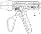
附图1为本申请实施例吻合器整体结构示意图;1 is a schematic diagram of the overall structure of the stapler according to the embodiment of the present application;
附图2为本申请实施例吻合器局部放大图;FIG. 2 is a partial enlarged view of the stapler according to the embodiment of the present application;
附图3为附图2去除部分壳体后的结构示意图;Figure 3 is a schematic structural diagram of Figure 2 after removing part of the casing;
附图4为推刀驱动杆两个视角的示意图;Accompanying drawing 4 is the schematic diagram of two perspectives of the pusher drive rod;
附图5为申请实施例吻合器剖视图;5 is a cross-sectional view of the stapler of the application embodiment;
附图6为附图5的局部放大图。FIG. 6 is a partial enlarged view of FIG. 5 .
具体对应附图标记如下:The specific corresponding reference signs are as follows:
端部执行器1、钉仓11、推钉件12、第一夹持件13、第二夹持件14、连接管2、手柄壳体3、观察开口31、执行驱动组件4、驱动套管41、推刀驱动杆42、行程标识件43、驱动连接杆44、手柄驱动组件5、按压手柄51。
具体实施方式Detailed ways
下面将结合本申请实施例中的附图,对本申请实施例中的技术方案进行清楚、完整地描述。显然,所描述的实施例仅仅是本申请一部分实施例,而不是全部的实施例。基于本申请中的实施例,本领域普通技术人员在没有作出创造性劳动的前提下所获得的所有其他实施例,都属于本申请保护的范围。The technical solutions in the embodiments of the present application will be clearly and completely described below with reference to the accompanying drawings in the embodiments of the present application. Obviously, the described embodiments are only a part of the embodiments of the present application, but not all of the embodiments. Based on the embodiments in this application, all other embodiments obtained by those of ordinary skill in the art without creative work fall within the protection scope of this application.
其中,本申请中,根据器械的使用描述,近端即靠近操作者的方向,远端即原理操作者的方向。Among them, in this application, according to the description of the use of the instrument, the proximal end is the direction close to the operator, and the distal end is the direction of the principle operator.
实施例:Example:
如图1-6所示,本实施例中,描述一种具有推钉指示功能的腔镜吻合器,其包括端部执行器1、连接管2、手柄壳体3、执行驱动组件4和手柄驱动组件5。其端部执行器1用于进入腔镜手术通道后对组织进行切割和缝合,端部执行器1具有第一夹持件13和第二夹持件14,端部执行器4通过连接管2与手柄壳体3连接,第一夹持件13与连接管5相对固定,第二夹持件14与连接管5相对转动,钉仓11设于第一夹持件13上,手柄驱动组件5的按压手柄51能够从近端的第一位置向远端的第二位置运动,以驱动端部执行器1的第一夹持件13和第二夹持件14执行夹持,并且在按压手柄51再次按动时,可以驱动钉仓实现吻合动作,包括推钉和切割。其中,本实施例中,夹持和吻合采用同一手柄进行驱动。As shown in Figures 1-6, in this embodiment, a laparoscopic stapler with a push nail indication function is described, which includes an
具体地,本实施例中,驱动切换机构包括执行驱动组件1和手柄驱动组件,执行驱动组件1至少部分设于连接管2内;执行驱动组件1包括驱动套管11和推刀驱动杆12,驱动套管11用于驱动端部执行器4执行闭合动作,推刀驱动杆42能够在初始位置和吻合位置之间滑动,用于驱动端部执行器1执行吻合动作,手柄驱动组件5则是通过接收操作者提供的驱动力,以将驱动力传递给执行驱动组件1,从而实现操作者和端部执行器的联动。具体地,本实施例中,端部执行器1包括钉仓11和位于钉仓11内的推钉件12,推钉件12与推刀驱动杆42通过驱动连接杆44固定连接,推钉件12包括推钉斜面,推刀驱动杆42从初始位置向吻合位置滑动时,驱动推钉件12,使得推钉件12通过推钉斜面将吻合钉推出钉仓11。Specifically, in this embodiment, the drive switching mechanism includes an
本实施例,由于手柄驱动组件5能够通过切换状态从而实现与执行驱动组件1中不同部件实现联动,因此可以使得通过按压同一手柄实现端部执行器实现不同的执行动作,即分别夹持和吻合。具体切换原理现有技术已经充分公开,也可以参考本申请背景技术中提及的现有技术,在此不再赘述。In this embodiment, since the
推刀驱动杆42靠近近端的一侧设有行程标识件43,手柄壳体3上设有与行程标识件43对应的观察开口31,当推刀驱动杆42在初始位置时,行程标识件43位于观察开口31对应的开口区域内,且当推刀驱动杆42在吻合位置时,行程标识件43位于观察开口31对应的开口区域外,通过行程标识件与观察开口的配合,操作者能够有效直观地判断腔镜吻合器是否完成推钉行程以及完成复位,解决了具有多行程控制的腔镜吻合器无法有效判断是推钉行程的技术问题。The side of the
本实施例中,行程标识件43为位于推刀驱动杆42侧面的凸起,在另一种实施例中,也可以是行程标识件43为位于推刀驱动杆42侧面的凹槽,或者是其他能够容易被识别的结构或者色彩。直接在推刀驱动杆设置行程标识件,可以直观地反应推刀驱动杆的行程完成情况,并且行程标识件的设置方式不会影响成体结构的布置。行程标识件43可以为单侧设置的一个,也可以为两个,两个行程标识件43对称设置在推刀驱动杆42两侧,观察开口31为两个,且分别与两个行程标识件43对应设置。In this embodiment, the
进一步地,为了保证器械的密封性和安全性,观察开口31为长条形,观察开口31上设有透明保护件,透明保护件为玻璃或透明塑料。Further, in order to ensure the airtightness and safety of the instrument, the observation opening 31 is in the shape of a long strip, and a transparent protective member is provided on the observation opening 31, and the transparent protective member is glass or transparent plastic.
具体操作过程为,当手柄驱动组件5处于驱动推刀驱动杆42状态时,握紧按压手柄51,带动推刀驱动杆42向远端运动,通过驱动连接杆44将驱动力提供至推钉件12,推钉件12通过推钉斜面将吻合钉推出钉仓11并且吻合成型,推刀驱动杆42位于吻合位置,此时观察开口31看不到43,表明远端推钉件12的推动动作已经完成。The specific operation process is as follows: when the
松开压手柄51后,在回复弹簧的作用下,推钉件12回复到原来的位置,此时推刀驱动杆42也回复到初始位置,因此能够在观察开口31中看到行程标识件43,表明推钉件12回复到位。After releasing the
根据以上描述可知,本申请具有如下优点:According to the above description, the present application has the following advantages:
(1)通过行程标识件与观察开口的配合,操作者能够有效直观地判断腔镜吻合器是否完成推钉行程以及完成复位,解决了具有多行程控制的腔镜吻合器无法有效判断是推钉行程的技术问题;(1) Through the cooperation between the stroke marker and the observation opening, the operator can effectively and intuitively judge whether the endoscopic stapler has completed the screw-pushing stroke and completed the reset, which solves the problem that the endoscopic stapler with multi-stroke control cannot effectively determine whether it is a screw-pushing stapler. technical issues with the itinerary;
(2)观察开口设置透明保护件有效保护了内部机构的密封性;(2) The observation opening is provided with a transparent protective member, which effectively protects the sealing of the internal mechanism;
(3)直接在推刀驱动杆设置行程标识件,可以直观地反应推刀驱动杆的行程完成情况,并且行程标识件的设置方式不会影响成体结构的布置。(3) Setting the stroke marker directly on the pusher drive rod can intuitively reflect the stroke completion of the pusher drive rod, and the setting method of the stroke marker will not affect the arrangement of the integrated structure.
在本申请的描述中,需要理解的是,术语“上”、“下”、“顶”、“底”等指示的方位或位置关系为基于附图所示的方位或位置关系,仅是为了便于描述本申请和简化描述,而不是指示或暗示所指的装置或元件必须具有特定的方位、以特定的方位构造和操作,因此不能理解为对本申请的限制。In the description of the present application, it should be understood that the orientation or positional relationship indicated by the terms "upper", "lower", "top", "bottom", etc. is based on the orientation or positional relationship shown in the accompanying drawings, and is only for the purpose of It is convenient to describe the application and to simplify the description, rather than indicating or implying that the device or element referred to must have a particular orientation, be constructed and operate in a particular orientation, and therefore should not be construed as limiting the application.
如上,我们完全按照本实用新型的宗旨进行了说明,但本实用新型并非局限于上述实施例和实施方法,且在不相互矛盾的情况下,实施例的特征可相互组合。相关技术领域的从业者可在本实用新型的技术思想许可的范围内进行不同的变化及实施。As above, we have described completely in accordance with the purpose of the present invention, but the present invention is not limited to the above-mentioned embodiments and implementation methods, and the features of the embodiments can be combined with each other under the condition of not contradicting each other. Practitioners in the relevant technical fields can make various changes and implementations within the scope permitted by the technical idea of the present invention.
Claims (8)
Priority Applications (1)
| Application Number | Priority Date | Filing Date | Title |
|---|---|---|---|
| CN202221234816.7UCN217408880U (en) | 2022-05-23 | 2022-05-23 | Endoscope anastomat with nail pushing indication function |
Applications Claiming Priority (1)
| Application Number | Priority Date | Filing Date | Title |
|---|---|---|---|
| CN202221234816.7UCN217408880U (en) | 2022-05-23 | 2022-05-23 | Endoscope anastomat with nail pushing indication function |
Publications (1)
| Publication Number | Publication Date |
|---|---|
| CN217408880Utrue CN217408880U (en) | 2022-09-13 |
Family
ID=83186525
Family Applications (1)
| Application Number | Title | Priority Date | Filing Date |
|---|---|---|---|
| CN202221234816.7UActiveCN217408880U (en) | 2022-05-23 | 2022-05-23 | Endoscope anastomat with nail pushing indication function |
Country Status (1)
| Country | Link |
|---|---|
| CN (1) | CN217408880U (en) |
- 2022
- 2022-05-23CNCN202221234816.7Upatent/CN217408880U/enactiveActive
Similar Documents
| Publication | Publication Date | Title |
|---|---|---|
| US11963679B2 (en) | Articulating surgical stapling instrument incorporating a two-piece E-beam firing mechanism | |
| JP7480153B2 (en) | Surgical stapler having tissue-engaging features about tissue-receiving pins - Patents.com | |
| CN104783853B (en) | Equipment for endoscopic procedure | |
| CN103654898B (en) | Linear seam cutting device | |
| JP6389007B2 (en) | Staple cartridge unit and medical stapler using the staple cartridge unit | |
| US20180078248A1 (en) | Interchangeable tools for surgical instruments | |
| CN203564287U (en) | End effector, surgical operating instrument and purse-string forceps | |
| US8342378B2 (en) | One handed stapler | |
| US8336751B2 (en) | Grasping jaw mechanism | |
| US8844790B2 (en) | Anvil-mounted dissecting tip for surgical stapling device | |
| US20180008261A1 (en) | Surgical instrument with sequential clamping and cutting | |
| US8424736B2 (en) | Grasping jaw mechanism | |
| US20110155783A1 (en) | Indicators for surgical staplers | |
| JP2018505729A (en) | Surgical clip applier with multiple clip supply mechanism | |
| US11337695B2 (en) | Staple cartridge assembly and medical stapler using the staple cartridge assembly | |
| DE602004015669D1 (en) | Surgical stapler with locking device activated on a spent cartridge | |
| CN204364052U (en) | A kind of nail-head component and there is the chamber mirror Endo-GIA of this nail-head component | |
| CN105796146B (en) | A kind of nail-head component and the hysteroscope Endo-GIA with the nail-head component | |
| CN101991450A (en) | Linear seam cutting device | |
| CN217408880U (en) | Endoscope anastomat with nail pushing indication function | |
| US11779333B2 (en) | Driving switching mechanism for stapling instrument and stapling instrument | |
| CN203564293U (en) | End effector, surgical operating instrument and purse-string forceps | |
| CN213489060U (en) | Nail bin assembly and medical anastomat with same | |
| CN104434241A (en) | End effector, surgical operating instrument and purse-string forceps | |
| CN102138815B (en) | Suture device for surgical operation |
Legal Events
| Date | Code | Title | Description |
|---|---|---|---|
| GR01 | Patent grant | ||
| GR01 | Patent grant |