CN217390967U - tendon braiding device - Google Patents
tendon braiding deviceDownload PDFInfo
- Publication number
- CN217390967U CN217390967UCN202220541582.4UCN202220541582UCN217390967UCN 217390967 UCN217390967 UCN 217390967UCN 202220541582 UCN202220541582 UCN 202220541582UCN 217390967 UCN217390967 UCN 217390967U
- Authority
- CN
- China
- Prior art keywords
- assembly
- tendon
- positioning portion
- weaving device
- suture
- Prior art date
- Legal status (The legal status is an assumption and is not a legal conclusion. Google has not performed a legal analysis and makes no representation as to the accuracy of the status listed.)
- Active
Links
- 210000002435tendonAnatomy0.000titleclaimsabstractdescription112
- 238000009954braidingMethods0.000titledescription30
- 238000009941weavingMethods0.000claimsabstractdescription37
- 230000006378damageEffects0.000abstractdescription7
- 230000009286beneficial effectEffects0.000abstractdescription6
- 230000002980postoperative effectEffects0.000abstractdescription4
- 210000001519tissueAnatomy0.000description42
- 238000000034methodMethods0.000description34
- 238000009940knittingMethods0.000description22
- 230000000712assemblyEffects0.000description14
- 238000000429assemblyMethods0.000description14
- 239000002131composite materialSubstances0.000description4
- 238000002360preparation methodMethods0.000description4
- 238000001356surgical procedureMethods0.000description4
- 238000010586diagramMethods0.000description3
- 210000003041ligamentAnatomy0.000description3
- 230000035515penetrationEffects0.000description3
- 238000000926separation methodMethods0.000description3
- 230000005540biological transmissionEffects0.000description2
- 230000000903blocking effectEffects0.000description2
- 210000000988bone and boneAnatomy0.000description2
- 230000008878couplingEffects0.000description2
- 238000010168coupling processMethods0.000description2
- 238000005859coupling reactionMethods0.000description2
- 230000001788irregularEffects0.000description2
- 208000025674Anterior Cruciate Ligament injuryDiseases0.000description1
- 206010061223Ligament injuryDiseases0.000description1
- 239000004698PolyethyleneSubstances0.000description1
- 208000021945Tendon injuryDiseases0.000description1
- 206010043248Tendon ruptureDiseases0.000description1
- 208000027418Wounds and injuryDiseases0.000description1
- 238000006243chemical reactionMethods0.000description1
- 201000010099diseaseDiseases0.000description1
- 208000037265diseases, disorders, signs and symptomsDiseases0.000description1
- 239000003814drugSubstances0.000description1
- 230000035876healingEffects0.000description1
- 210000003127kneeAnatomy0.000description1
- 238000012986modificationMethods0.000description1
- 230000004048modificationEffects0.000description1
- 230000000399orthopedic effectEffects0.000description1
- -1polyethylenePolymers0.000description1
- 229920000573polyethylenePolymers0.000description1
- 230000001568sexual effectEffects0.000description1
Images


Landscapes
- Looms (AREA)
Abstract
Translated fromChinese
Description
Translated fromChinese技术领域technical field
本实用新型涉及医疗器械技术领域,特别涉及一种肌腱编织装置。The utility model relates to the technical field of medical instruments, in particular to a tendon weaving device.
背景技术Background technique
骨科及运动医学的损伤性疾病中交叉韧带损伤是较常见的疾病之一,前交叉韧带损伤是膝关节肌腱损伤中发病率是最高的。在交叉韧带手术中,肌腱编织是很重要的一个步骤,编织后的肌腱的质量对交叉韧带重建手术成功与否会产生重要影响。肌腱编织失败会直接导致交叉韧带重建手术失败。Cruciate ligament injury is one of the more common diseases in orthopedics and sports medicine. Anterior cruciate ligament injury is the highest incidence of knee tendon injury. In cruciate ligament surgery, tendon weaving is an important step, and the quality of the woven tendon will have an important impact on the success of cruciate ligament reconstruction surgery. Failure of tendon braiding can directly lead to failure of cruciate ligament reconstruction surgery.
目前临床上常用的肌腱编织方法为:使用肌腱固定夹,夹持肌腱,用带有2号不可吸收聚乙烯缝线的圆针将肌腱两端编织缝合,缝合线跨肌腱中线,有一定交叉。但是在编织过程中,一方面无法控制针距,如果针距过小,编织线紧密包裹肌腱,在肌腱与骨隧道之间形成空隙,会影响腱骨愈合。若针距过大,则会造成编织段过长,在关节腔内会有编织线外露,可能会引起滑膜反应。另一方面,目前在肌腱编织中常用的带线缝针为半弧形圆针,因半弧形缝针需要两把持针钳配合完成肌腱编织操作,操作困难且时间长,目前常用的编织方法需要进行两侧的编织,因此较长时间才能完成肌腱编织,延长了手术时间,影响手术的进行。而半弧形圆针的针尖对肌腱组织损伤较大,容易造成对肌腱的线性切割,从而造成肌腱撕裂。At present, the commonly used tendon knitting method in clinical practice is as follows: use a tendon fixation clip to clamp the tendon, and use a round needle with No. 2 non-absorbable polyethylene suture to weave and suture both ends of the tendon. However, during the knitting process, on the one hand, the needle pitch cannot be controlled. If the needle pitch is too small, the braided thread tightly wraps the tendon, forming a gap between the tendon and the bone tunnel, which will affect the healing of the tendon and bone. If the needle distance is too large, the braided segment will be too long, and the braided thread will be exposed in the joint cavity, which may cause synovial reaction. On the other hand, the commonly used stitching needles in tendon knitting are semi-arc circular needles. Because the semi-arc stitching needle requires two holding needle forceps to complete the tendon knitting operation, the operation is difficult and time-consuming. The currently commonly used knitting method Both sides need to be braided, so it takes a long time to complete the tendon braiding, which prolongs the operation time and affects the operation. On the other hand, the needle tip of the semi-arc-shaped round needle causes great damage to the tendon tissue, which is likely to cause linear cutting of the tendon, resulting in tendon tearing.
实用新型内容Utility model content
本实用新型的目的在于提供一种肌腱编织装置,以解决现有的肌腱编织易伤害肌腱组织而导致编织失败的问题。The purpose of the utility model is to provide a tendon weaving device to solve the problem that the existing tendon weaving easily damages the tendon tissue and causes the weaving failure.
为解决上述技术问题,本实用新型提供一种肌腱编织装置,其包括:第一组合件、第二组合件以及缝线;In order to solve the above technical problems, the present utility model provides a tendon braiding device, which comprises: a first assembly, a second assembly and a suture;
所述第一组合件与所述第二组合件沿各自的轴向分别具有相对的头端和尾端,所述第一组合件的尾端通过所述缝线与所述第二组合件的尾端连接;The first assembly and the second assembly respectively have opposite head ends and tail ends along the respective axial directions, and the tail end of the first assembly is connected with the second assembly through the suture. tail connection;
所述第一组合件与所述第二组合件用于沿相同的头尾朝向可拆卸地装配。The first assembly and the second assembly are used for detachable assembly along the same head-to-tail orientation.
可选的,在所述肌腱编织装置中,所述第一组合件具有内腔,所述内腔朝所述第一组合件的尾端开放,所述第二组合件用于自所述内腔开放的一端穿入,以与所述第一组合件装配。Optionally, in the tendon braiding device, the first assembly has an inner cavity, and the inner cavity is open toward the tail end of the first assembly, and the second assembly is used for accessing from the inner cavity. The open end of the cavity is threaded for assembly with the first assembly.
可选的,所述肌腱编织装置还包括导向轨,所述导向轨与所述第一组合件的尾端连接,并沿所述第一组合件的轴向延伸,所述导向轨用于引导所述第二组合件穿入所述内腔的方向。Optionally, the tendon braiding device further includes a guide rail, the guide rail is connected with the tail end of the first assembly and extends along the axial direction of the first assembly, and the guide rail is used for guiding The direction in which the second assembly penetrates the inner cavity.
可选的,所述缝线通过所述导向轨与所述第一组合件的尾端连接;或者,所述缝线直接与所述第一组合件的尾端连接。Optionally, the suture is connected to the tail end of the first assembly through the guide rail; or, the suture is directly connected to the tail of the first assembly.
可选的,在所述肌腱编织装置中,所述第二组合件的横截面为圆形,所述导向轨的横截面为与所述第二组合件的横截面相适配的弧形。Optionally, in the tendon braiding device, the cross section of the second assembly is circular, and the cross section of the guide rail is an arc shape adapted to the cross section of the second assembly.
可选的,在所述肌腱编织装置中,第一组合件的外轮廓的横截面为圆形,和/或,所述内腔的横截面为圆形。Optionally, in the tendon braiding device, the cross-section of the outer contour of the first assembly is circular, and/or the cross-section of the inner cavity is circular.
可选的,在所述肌腱编织装置中,所述第二组合件的外轮廓与所述内腔相适配,所述第二组合件在穿入所述内腔后,被所述内腔限制沿径向的移动。Optionally, in the tendon braiding device, the outer contour of the second assembly is adapted to the inner cavity, and after the second assembly is penetrated into the inner cavity, it is absorbed by the inner cavity. Limit movement in the radial direction.
可选的,在所述肌腱编织装置中,所述第一组合件的内腔表面具有第一定位部,所述第二组合件的外表面具有第二定位部,所述第一定位部用于与所述第二定位部相配合,以限制所述第一组合件相对于所述第二组合件的周向位置。Optionally, in the tendon braiding device, an inner cavity surface of the first assembly has a first positioning portion, an outer surface of the second assembly has a second positioning portion, and the first positioning portion is provided with a first positioning portion. for cooperating with the second positioning part to limit the circumferential position of the first assembly relative to the second assembly.
可选的,在所述肌腱编织装置中,所述第一定位部包括沿所述内腔周向开设的第一凹凸结构,所述第二定位部包括沿所述第二组合件的外表面的周向设置的第二凹凸结构,所述第二凹凸结构用于与所述第一凹凸结构相适配卡合。Optionally, in the tendon braiding device, the first positioning portion includes a first concave-convex structure opened along the circumferential direction of the inner cavity, and the second positioning portion includes an outer surface along the second assembly. The second concave-convex structure is arranged in the circumferential direction, and the second concave-convex structure is used for matching and engaging with the first concave-convex structure.
可选的,在所述肌腱编织装置中,第一组合件的头端为尖锐形,所述第二组合件的头端为钝形。Optionally, in the tendon braiding device, the head end of the first assembly is sharp, and the head end of the second assembly is blunt.
可选的,在所述肌腱编织装置中,所述第一组合件的外表面和/或所述第二组合件的外表面具有沿轴向分布的刻度。Optionally, in the tendon braiding device, the outer surface of the first assembly and/or the outer surface of the second assembly has graduations distributed along the axial direction.
可选的,在所述肌腱编织装置中,所述第一组合件的尾端具有第一定位部,所述第二组合件的尾端具有第二定位部,所述第一定位部用于与所述第二定位部相配合,以限制所述第一组合件相对于所述第二组合件的周向位置。Optionally, in the tendon braiding device, the tail end of the first assembly has a first positioning portion, and the tail end of the second assembly has a second positioning portion, and the first positioning portion is used for Cooperate with the second positioning portion to limit the circumferential position of the first assembly relative to the second assembly.
可选的,在所述肌腱编织装置中,所述第一定位部包括沿所述第一组合件的轴向开设的第一凹凸结构,所述第二定位部包括沿所述第二组合件的轴向设置的第二凹凸结构,所述第二凹凸结构用于与所述第一凹凸结构相适配卡合。Optionally, in the tendon braiding device, the first positioning portion includes a first concave-convex structure opened along the axial direction of the first assembly, and the second positioning portion includes a structure along the second assembly. The axially arranged second concave-convex structure is used for matching and engaging with the first concave-convex structure.
为解决上述技术问题,本实用新型还提供一种编织方法,其用于编织束状的待编织对象;所述编织方法利用如上所述的肌腱编织装置;所述编织方法包括:In order to solve the above-mentioned technical problems, the present invention also provides a weaving method, which is used for weaving a bundle-shaped object to be woven; the weaving method utilizes the above-mentioned tendon weaving device; the weaving method comprises:
准备过程,其包括:将所述第一组合件与所述第二组合件沿相同的头尾朝向装配,形成组合体;以及将所述缝线套在所述待编织对象上;The preparation process includes: assembling the first assembly and the second assembly along the same head-to-tail orientation to form an assembly; and wrapping the suture on the object to be knitted;
编织过程,其包括:所述组合体的头端朝向待编织对象,并沿所述待编织对象的径向自所述待编织对象中穿过;收拉所述组合体,以使所述缝线缠绕于所述待编织对象上;以及分离所述第一组合件与所述第二组合件,将所述第一组合件与所述第二组合件分别绕过所述待编织对象后再次装配;以及The weaving process includes: the head end of the composite body faces the object to be knitted, and passes through the object to be knitted along the radial direction of the object to be knitted; retracting and pulling the composite body to make the seam The thread is wound on the object to be knitted; and the first assembly and the second assembly are separated, and the first assembly and the second assembly are respectively passed around the object to be knitted and then again assembly; and
重复编织过程,其包括:重复执行所述编织过程中的至少部分步骤,直至完成对所述待编织对象的编织。Repeating the knitting process includes: repeating at least part of the steps in the knitting process until the knitting of the object to be knitted is completed.
可选的,在所述的编织方法中,在执行所述重复编织过程时,沿所述待编织对象的轴向依次移动预定间隔;所述预定间隔以所述第一组合件和/或所述第二组合件的刻度为参考。Optionally, in the weaving method, when the repeated weaving process is performed, a predetermined interval is sequentially moved along the axial direction of the object to be knitted; The scale of the second assembly is for reference.
可选的,在所述的编织方法中,在将所述第一组合件与所述第二组合件分别绕过所述待编织对象后再次装配的步骤中,所述第一组合件与所述第二组合件分别绕过所述待编织对象半周,以使重复执行所述组合体自所述待编织对象中穿过的步骤时,所述组合体的穿入点位于所述待编织对象的同一周向位置上。Optionally, in the weaving method, in the step of reassembling the first assembly and the second assembly after bypassing the object to be knitted respectively, the first assembly and the second assembly are reassembled. The second assembly goes around the object to be knitted for half a circumference respectively, so that when the step of passing the assembly through the object to be knitted is repeated, the penetration point of the assembly is located at the object to be knitted at the same circumferential position.
综上所述,在本实用新型提供的肌腱编织装置及编织方法中,所述肌腱编织装置包括:第一组合件、第二组合件以及缝线;所述第一组合件与所述第二组合件沿各自的轴向分别具有相对的头端和尾端,所述第一组合件的尾端通过所述缝线与所述第二组合件的尾端连接;所述第一组合件与所述第二组合件用于沿相同的头尾朝向可拆卸地装配。To sum up, in the tendon braiding device and braiding method provided by the present invention, the tendon braiding device includes: a first assembly, a second assembly and a suture; the first assembly and the second assembly The assemblies respectively have opposite head ends and tail ends along respective axial directions, and the tail ends of the first assemblies are connected with the tail ends of the second assemblies through the sutures; the first assemblies are connected to The second assembly is intended to be removably assembled in the same head-to-tail orientation.
如此配置,在将第一组合件和第二组合件组合装配后,可一次穿过待编织的肌腱组织,并拉紧缝线。而后可将第一组合件和第二组合件分离,令其环绕待编织的肌腱组织后,可再次将第一组合件和第二组合件组合装配,以重复执行穿过-拉紧-分离的步骤,来完成对待编织的肌腱组织的编织过程。由于第一组合件和第二组合件组合装配后,一次穿过待编织的肌腱组织,仅有一个穿刺点,即可完成肌腱两侧的缝合,一方面节省了手术时间,提高了肌腱编织的效率;另一方面减少了对肌腱组织的损伤,有利于患者术后的康复。So configured, after the combined assembly of the first and second assemblies, the tendon tissue to be braided can be threaded in one pass and the sutures tightened. The first and second assemblies can then be separated so that they surround the tendon tissue to be braided, and the first and second assemblies can be assembled again to repeat the thread-tightening-separation process. steps to complete the braiding process of the tendon tissue to be braided. After the first assembly and the second assembly are assembled, they pass through the tendon tissue to be knitted at one time, and only one puncture point can complete the suture on both sides of the tendon. Efficiency; on the other hand, it reduces the damage to the tendon tissue, which is beneficial to the postoperative rehabilitation of patients.
附图说明Description of drawings
本领域的普通技术人员将会理解,提供的附图用于更好地理解本实用新型,而不对本实用新型的范围构成任何限定。其中:Those of ordinary skill in the art will appreciate that the accompanying drawings are provided for a better understanding of the present invention and do not constitute any limitation to the scope of the present invention. in:
图1是本实用新型实施例的肌腱编织装置的示意图;1 is a schematic diagram of a tendon braiding device according to an embodiment of the present invention;
图2a~图2c是本实用新型实施例的编织方法的编织过程图;2a to 2c are knitting process diagrams of the knitting method according to the embodiment of the present invention;
图3是本实用新型实施例的第一组合件的轴向的剖面示意图;3 is a schematic cross-sectional view of the first assembly in the axial direction of the embodiment of the present invention;
图4是本实用新型另一实施例的肌腱编织装置的示意图。4 is a schematic diagram of a tendon braiding device according to another embodiment of the present invention.
附图中:In the attached picture:
1-第一组合件;10-内腔;11-第一定位部;2-第二组合件;21-第二定位部;3-缝线;4-肌腱组织;41-第一预定针孔;42-第二预定针孔;5-导向轨;6-刻度;7-组合体。1-first assembly; 10-inner cavity; 11-first positioning part; 2-second assembly; 21-second positioning part; 3-suture; 4-tendon tissue; 41-first predetermined pinhole ; 42- the second predetermined pinhole; 5- guide rail; 6- scale; 7- combination.
具体实施方式Detailed ways
为使本实用新型的目的、优点和特征更加清楚,以下结合附图和具体实施例对本实用新型作进一步详细说明。需说明的是,附图均采用非常简化的形式且未按比例绘制,仅用以方便、明晰地辅助说明本实用新型实施例的目的。此外,附图所展示的结构往往是实际结构的一部分。特别的,各附图需要展示的侧重点不同,有时会采用不同的比例。In order to make the purpose, advantages and features of the present utility model clearer, the present utility model will be further described in detail below with reference to the accompanying drawings and specific embodiments. It should be noted that the accompanying drawings are all in a very simplified form and are not drawn to scale, and are only used to facilitate and clearly assist the purpose of explaining the embodiments of the present invention. Furthermore, the structures shown in the drawings are often part of the actual structure. In particular, each drawing needs to show different emphases, and sometimes different scales are used.
如在本实用新型中所使用的,单数形式“一”、“一个”以及“该”包括复数对象,术语“或”通常是以包括“和/或”的含义而进行使用的,术语“若干”通常是以包括“至少一个”的含义而进行使用的,术语“至少两个”通常是以包括“两个或两个以上”的含义而进行使用的,此外,术语“第一”、“第二”、“第三”仅用于描述目的,而不能理解为指示或暗示相对重要性或者隐含指明所指示的技术特征的数量。由此,限定有“第一”、“第二”、“第三”的特征可以明示或者隐含地包括一个或者至少两个该特征,“一端”与“另一端”以及“近端”与“远端”通常是指相对应的两部分,其不仅包括端点。此外,如在本实用新型中所使用的,“安装”、“相连”、“连接”,一元件“设置”于另一元件,应做广义理解,通常仅表示两元件之间存在连接、耦合、配合或传动关系,且两元件之间可以是直接的或通过中间元件间接的连接、耦合、配合或传动,而不能理解为指示或暗示两元件之间的空间位置关系,即一元件可以在另一元件的内部、外部、上方、下方或一侧等任意方位,除非内容另外明确指出外。对于本领域的普通技术人员而言,可以根据具体情况理解上述术语在本实用新型中的具体含义。此外,诸如上方、下方、上、下、向上、向下、左、右等的方向术语相对于示例性实施方案如它们在图中所示进行使用,向上或上方向朝向对应附图的顶部,向下或下方向朝向对应附图的底部。As used in this specification, the singular forms "a", "an" and "the" include plural referents, the term "or" is generally used in a sense including "and/or", and the term "a number of" " is usually used in the sense including "at least one", the term "at least two" is usually used in the meaning including "two or more", in addition, the terms "first", " "Second" and "Third" are for descriptive purposes only, and cannot be understood as indicating or implying relative importance or implying the number of indicated technical features. Thus, a feature defined as "first", "second", "third" may expressly or implicitly include one or at least two of those features, "one end" and "the other end" and "proximal end" and "Distal" generally refers to corresponding two parts, which includes not only the endpoints. In addition, as used in the present invention, "installed", "connected" and "connected", one element is "arranged" on another element, should be understood in a broad sense, usually only means that there is a connection or coupling between two elements , cooperation or transmission relationship, and the connection, coupling, cooperation or transmission between the two elements may be direct or indirect through intermediate elements, and should not be interpreted as indicating or implying the spatial positional relationship between the two elements, that is, an element may be in Any orientation inside, outside, above, below or to one side of another element unless the content clearly dictates otherwise. For those of ordinary skill in the art, the specific meanings of the above terms in the present invention can be understood according to specific situations. Also, directional terms such as above, below, up, down, up, down, left, right, etc., are used relative to the exemplary embodiments as they are shown in the figures, with an upward or upward orientation toward the top of the corresponding figure, The downward or downward direction is towards the bottom of the corresponding drawing.
本实用新型的目的在于提供一种肌腱编织装置,以解决现有的肌腱编织易伤害肌腱组织而导致编织失败的问题。The purpose of the utility model is to provide a tendon weaving device to solve the problem that the existing tendon weaving easily damages the tendon tissue and causes the weaving failure.
以下参考附图进行描述。The following description is made with reference to the accompanying drawings.
请参考图1,本实用新型实施例提供一种肌腱编织装置,其包括:第一组合件1、第二组合件2以及缝线3;所述第一组合件1与所述第二组合件2沿各自的轴向分别具有相对的头端(为便于叙述,在图1中,第一组合件1的头端为1a,第二组合件2的头端为2a)和尾端(为便于叙述,在图1中,第一组合件1的尾端为1b,第二组合件2的尾端为2b),所述第一组合件1的尾端1b通过所述缝线3与所述第二组合件2的尾端2b连接;所述第一组合件1与所述第二组合件2用于沿相同的头尾朝向可拆卸地装配。需要说明的,第一组合件1或第二组合件2的形状并不限于呈直线形,还可以是曲线形或不规则形,则相应的,第一组合件1或第二组合件2的轴向也呈曲线形或不规则形。Please refer to FIG. 1 , an embodiment of the present invention provides a tendon braiding device, which includes: a
请结合参考图2a~图2c,本实用新型实施例还提供一种编织方法,其用于编织束状的待编织对象,所述编织方法包括:Please refer to FIG. 2a to FIG. 2c in combination. The embodiment of the present invention further provides a knitting method, which is used for knitting a bundle-shaped object to be knitted. The knitting method includes:
准备过程S1,其包括:将所述第一组合件1与所述第二组合件2沿相同的头尾朝向装配,形成组合体7;以及将所述缝线3套在所述待编织对象上;Preparation process S1, which includes: assembling the
编织过程S2,其包括:Weaving process S2, which includes:
所述组合体7的头端7a朝向待编织对象,并沿所述待编织对象的径向自所述待编织对象中穿过,此时的状态请参考图2a;The
收拉所述组合体,以使所述缝线3缠绕于所述待编织对象上;以及分离所述第一组合件1与所述第二组合件2,此时的状态请参考图2b;Pulling and retracting the assembly, so that the
将所述第一组合件1与所述第二组合件2分别绕过所述待编织对象后再次装配,此时的状态请参考图2c;以及The
重复编织过程S3,其包括:重复执行所述编织过程S2中的至少部分步骤,直至完成对所述待编织对象的编织。Repeating the knitting process S3 includes: repeating at least part of the steps in the knitting process S2 until the knitting of the object to be knitted is completed.
为便于叙述,本实施例以肌腱组织4作为待编织对象的示例进行说明。需要说明的,肌腱仅为待编织对象的一个示范例,而非对待编织对象的限定。在其它的一些应用场景下,还可以将肌腱假体、动物的肌腱等作为待编织对象,利用本实施例提供的肌腱编织装置和编织方法对其进行模拟手术、训练或施力标定等操作,本实用新型对此不限。特别的,图2a~图2c中,肌腱组织4以一圆柱体表示,实际中,其可包括束状的多根肌腱。For convenience of description, this embodiment takes the
准备过程S1主要是在缝合肌腱组织4的第一针前的操作过程,在将第一组合件1与第二组合件2组合装配形成组合体7后,缝线3实际上将形成一个闭合的环,其可以环绕套设在肌腱组织4外。实际中,由于肌腱组织4常被取出人体后夹持在肌腱夹持装置(请参考现有技术,图2a~图2c中未图示)上,为了便于操作,也可以先将缝线3穿在肌腱组织4与肌腱夹持装置之间,而后再将第一组合件1与第二组合件2组合装配,本实施例对准备过程S1中的操作步骤不作限制,既可以先组合第一组合件1与第二组合件2,也可以先套缝线3。The preparation process S1 is mainly an operation process before the first stitch of the
编织过程S2中,由于缝线3形成的闭合的环套设在肌腱组织4外,而缝线3的两个线头分别与第一组合件1的尾端1b和第二组合件2的尾端2b连接,因此将第一组合件1与第二组合件2的组合体7从第一预定针孔41处穿过,可将缝线3的两个线头连带着一同穿过肌腱组织4,如图2a所示。In the knitting process S2, the closed loop formed by the
拉紧缝线3,可使缝线3缠绕于所述肌腱组织4上。进而分离第一组合件1与第二组合件2,将第一组合件1与第二组合件2分别沿不同的方向绕过肌腱组织4,如图2b所示。Tensioning the
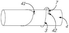
而后再次组合装配第一组合件1与第二组合件2形成组合体7,并准备穿入第二预定针孔42,使缝线3再次形成的闭合的环套设在肌腱组织4外,如图2c所示。Then, the
在完成编织过程S2后,即完成了第一针的缝合编织过程。进而执行重复编织过程S3,可依次完成若干针的缝合编织,直至完成对肌腱组织4的编织。After the knitting process S2 is completed, the stitching knitting process of the first needle is completed. Further, the repeated knitting process S3 is performed, and the suture knitting of several needles can be completed in sequence until the knitting of the
优选的,在将所述第一组合件1与所述第二组合件2分别绕过肌腱组织4后再次装配的步骤中,所述第一组合件1与所述第二组合件2分别绕过肌腱组织4半周,以使重复执行所述组合体自肌腱组织4中穿过的步骤时,所述组合体7的穿入点(第一预定针孔41、第二预定针孔42以及后续的若干针孔)位于肌腱组织4的同一周向位置上。即多个穿入点排列成平行于肌腱组织之轴向的一直线。Preferably, in the step of reassembling after passing the
如此配置,在将第一组合件1和第二组合件2组合装配后,可一次穿过待编织的肌腱组织4,并拉紧缝线3。而后可将第一组合件1和第二组合件2分离,令其环绕待编织的肌腱组织4后,可再次将第一组合件1和第二组合件2组合装配,以重复执行穿过-拉紧-分离的步骤,来完成对待编织的肌腱组织4的编织过程。由于第一组合件1和第二组合件2组合装配后,一次穿过待编织的肌腱组织4,仅有一个穿刺点,即可完成肌腱两侧的缝合,一方面节省了手术时间,提高了肌腱编织的效率;另一方面减少了对肌腱组织4的损伤,有利于患者术后的康复。In this configuration, after the combined assembly of the
请参考图3,在一个可替代的示范例中,所述第一组合件1具有内腔10,所述内腔10朝所述第一组合件1的尾端1b开放,所述第二组合件2用于自所述内腔10开放的一端穿入,以与所述第一组合件1装配。第一组合件1和第二组合件2内外装配的方式,一方面便于操作,另一方面也有利于减小第一组合件1和第二组合件2的组合体穿过肌腱组织4的阻力,有利于减小对肌腱组织4的性切割,避免肌腱断裂。Referring to FIG. 3 , in an alternative example, the
可选的,第一组合件1的头端1a为尖锐形。需要说明的,这里的尖锐形,如可为锥形或棱锥,其尖端的角度优选小于30°,以便于对肌腱组织4进行穿刺。优选的,第一组合件1的外轮廓的横截面为圆形,其大致为一圆柱状的针状件。优选的,所述第二组合件2的头端为钝形,钝形如可为钝圆形等形状,也可以如圆台等形状,其相对于尖锐形,不易刺破操作者的手。Optionally, the head end 1a of the
进一步的,所述第二组合件2的外轮廓与所述内腔10相适配,所述第二组合件2在穿入所述内腔10后,被所述内腔10限制沿径向的移动。在一个示范例中,所述内腔10的横截面为圆形,所述第二组合件2的横截面为圆形,第二组合件2的外径与内腔10的内径相适配,即第二组合件2的外径略小于内腔10的内径,第二组合件2能够较为紧密地配合,但应保证第二组合件2的插入拔出无卡涩感,其能够顺滑地插入内腔10或从内腔10中拔出。当然本实用新型对第二组合件2的外轮廓以及内腔10的形状不作特别的限制,其并非限制必须为圆形。例如在其它的一些实施例中,第二组合件2的外轮廓和/或内腔10的形状为多边形,只要两者能够相互配合即可。Further, the outer contour of the
可选的,所述肌腱编织装置还包括导向轨5,所述导向轨5与所述第一组合件1的尾端1b连接,并沿所述第一组合件1的轴向延伸,所述导向轨5用于引导所述第二组合件2穿入所述内腔10的方向。导向轨5的设置,用于在第二组合件2穿入内腔10时对第二组合件2进行引导。具体的,第二组合件2在穿入内腔10前,可先抵靠于第二组合件2上,然后顺着导向轨5滑入内腔10中。优选的,所述导向轨5的横截面为与所述第二组合件2的横截面相适配的弧形。弧形的导向轨5能够顺滑地对第二组合件2进行引导。Optionally, the tendon braiding device further includes a
可选的,所述缝线3通过所述导向轨5与所述第一组合件1的尾端连接;或者,所述缝线3直接与所述第一组合件1的尾端连接。需要说明的,第一组合件1的尾端通过缝线3与第二组合件2的尾端连接,并非限定所述缝线3与所述第一组合件1的尾端必须是直接连接的,两者也可以是间接连接的,例如缝线3与第一组合件1两者可通过导向轨5间接地连接。当然另一些实施例中,缝线3也可以与第一组合件1的尾端直接连接,此时导向轨5仅起到引导作用。Optionally, the
可选的,所述第一组合件1的外表面和/或所述第二组合件2的外表面具有沿轴向分布的刻度6。刻度6如可按2mm的间距分布。使用时,在编织过程S2中,缝线3缠绕于肌腱组织4上,并分离第一组合件1与第二组合件2后,可将第一组合件1或第二组合件2横过来作为标尺来使用,比划着确定下一个穿刺点的大致位置。进而再将第一组合件1或第二组合件2组合装配,继续穿刺和编织的过程。优选的,在执行所述重复编织过程S3时,沿肌腱组织4的轴向依次移动预定间隔;所述预定间隔以所述第一组合件1和/或所述第二组合件2的刻度6为参考,例如相邻两个穿刺点(例如第一预定针孔41和第二预定针孔42)的间距可为2mm。Optionally, the outer surface of the
请参考图4,可选的,所述第一组合件1的尾端1b具有第一定位部11,所述第二组合件2的尾端2b具有第二定位部21,所述第一定位部11用于与所述第二定位部21相配合,以限制所述第一组合件1相对于所述第二组合件2的周向位置。在一些实施例中,第一组合件1的内腔10和第二组合件2的形状都是圆形的,则两者能够产生相对的周向转动,这容易使缝线3产生扭曲。而第一定位部11与第二定位部21相配合后,可以限制第一组合件1相对于第二组合件2的周向位置,从而限制两者产生相对的周向转动。Please refer to FIG. 4 , optionally, the
在一个可替代的示范例中,所述第一定位部11包括沿所述第一组合件1的轴向开设的第一凹凸结构,第一凹凸结构可设置在第一组合件1的尾端面上;所述第二定位部包括沿所述第二组合件2的轴向设置的第二凹凸结构,第二组合件2的尾端如可包括一个外径与第一组合件1的外径相匹配的堵台,该堵台具有朝向第二组合件2的头端2a方向的结合面,第二凹凸结构可设置在该结合面上。所述第二凹凸结构用于与所述第一凹凸结构相适配卡合。第一凹凸结构和第二凹凸结构如可为相适配的齿轮,或其它的形状,本实用新型对此不限。In an alternative example, the
在另一个可替代的示范例中(未图示),所述第一组合件1的内腔表面具有第一定位部11,所述第二组合件2的外表面具有第二定位部21,所述第一定位部11用于与所述第二定位部21相配合,以限制所述第一组合件1相对于所述第二组合件2的周向位置。可选的,所述第一定位部11包括沿所述内腔10的周向开设的第一凹凸结构,所述第二定位部2包括沿所述第二组合件2的外表面的周向设置的第二凹凸结构,所述第一凹凸结构与第二凹凸结构相互适配卡合。In another alternative example (not shown), the inner cavity surface of the
综上所述,在本实用新型提供的肌腱编织装置及编织方法中,所述肌腱编织装置包括:第一组合件、第二组合件以及缝线;所述第一组合件与所述第二组合件沿各自的轴向分别具有相对的头端和尾端,所述第一组合件的尾端通过所述缝线与所述第二组合件的尾端连接;所述第一组合件与所述第二组合件用于沿相同的头尾朝向可拆卸地装配。如此配置,在将第一组合件和第二组合件组合装配后,可一次穿过待编织的肌腱组织,并拉紧缝线。而后可将第一组合件和第二组合件分离,令其环绕待编织的肌腱组织后,可再次将第一组合件和第二组合件组合装配,以重复执行穿过-拉紧-分离的步骤,来完成对待编织的肌腱组织的编织过程。由于第一组合件和第二组合件组合装配后,一次穿过待编织的肌腱组织,仅有一个穿刺点,即可完成肌腱两侧的缝合,一方面节省了手术时间,提高了肌腱编织的效率;另一方面减少了对肌腱组织的损伤,有利于患者术后的康复。To sum up, in the tendon braiding device and braiding method provided by the present invention, the tendon braiding device includes: a first assembly, a second assembly and a suture; the first assembly and the second assembly The assemblies respectively have opposite head ends and tail ends along respective axial directions, and the tail ends of the first assemblies are connected with the tail ends of the second assemblies through the sutures; the first assemblies are connected to The second assembly is intended to be removably assembled in the same head-to-tail orientation. So configured, after the combined assembly of the first and second assemblies, the tendon tissue to be braided can be threaded in one pass and the sutures tightened. The first and second assemblies can then be separated so that they surround the tendon tissue to be braided, and the first and second assemblies can be assembled again to repeat the thread-tightening-separation process. steps to complete the braiding process of the tendon tissue to be braided. After the first assembly and the second assembly are assembled, they pass through the tendon tissue to be knitted at one time, and only one puncture point can complete the suture on both sides of the tendon. Efficiency; on the other hand, it reduces the damage to the tendon tissue, which is beneficial to the postoperative rehabilitation of patients.
需要说明的,上述若干实施例之间可相互组合。上述描述仅是对本实用新型较佳实施例的描述,并非对本实用新型范围的任何限定,本实用新型领域的普通技术人员根据上述揭示内容做的任何变更、修饰,均属于权利要求书的保护范围。It should be noted that the above-mentioned several embodiments may be combined with each other. The above description is only a description of the preferred embodiments of the present invention, and does not limit the scope of the present invention. Any changes and modifications made by those of ordinary skill in the field of the present invention according to the above disclosure belong to the protection scope of the claims. .
Claims (13)
Priority Applications (1)
| Application Number | Priority Date | Filing Date | Title |
|---|---|---|---|
| CN202220541582.4UCN217390967U (en) | 2022-03-11 | 2022-03-11 | tendon braiding device |
Applications Claiming Priority (1)
| Application Number | Priority Date | Filing Date | Title |
|---|---|---|---|
| CN202220541582.4UCN217390967U (en) | 2022-03-11 | 2022-03-11 | tendon braiding device |
Publications (1)
| Publication Number | Publication Date |
|---|---|
| CN217390967Utrue CN217390967U (en) | 2022-09-09 |
Family
ID=83138936
Family Applications (1)
| Application Number | Title | Priority Date | Filing Date |
|---|---|---|---|
| CN202220541582.4UActiveCN217390967U (en) | 2022-03-11 | 2022-03-11 | tendon braiding device |
Country Status (1)
| Country | Link |
|---|---|
| CN (1) | CN217390967U (en) |
Cited By (2)
| Publication number | Priority date | Publication date | Assignee | Title |
|---|---|---|---|---|
| CN116115285A (en)* | 2023-01-10 | 2023-05-16 | 北京市春立正达医疗器械股份有限公司 | Tendon braiding device capable of rapidly switching suture sleeve |
| WO2023169233A1 (en)* | 2022-03-11 | 2023-09-14 | 上海竞捷医疗科技有限公司 | Tendon braiding device and braiding method |
- 2022
- 2022-03-11CNCN202220541582.4Upatent/CN217390967U/enactiveActive
Cited By (3)
| Publication number | Priority date | Publication date | Assignee | Title |
|---|---|---|---|---|
| WO2023169233A1 (en)* | 2022-03-11 | 2023-09-14 | 上海竞捷医疗科技有限公司 | Tendon braiding device and braiding method |
| CN116763496A (en)* | 2022-03-11 | 2023-09-19 | 上海竞捷医疗科技有限公司 | Tendon braiding device and braiding method |
| CN116115285A (en)* | 2023-01-10 | 2023-05-16 | 北京市春立正达医疗器械股份有限公司 | Tendon braiding device capable of rapidly switching suture sleeve |
Similar Documents
| Publication | Publication Date | Title |
|---|---|---|
| CN217390967U (en) | tendon braiding device | |
| US5439469A (en) | Wound closure device | |
| CA2813597C (en) | Method and apparatus for passing suture through tissue | |
| JP6594418B2 (en) | Instruments and methods for suturing tissue | |
| JP6332889B2 (en) | Achilles tendon suture device | |
| BR112014015874B1 (en) | SUTURE SET, METHOD OF MANUFACTURING A SUTURE SET, OPERATING KIT AND OPERATING DEVICE | |
| JP2010505535A (en) | Shape memory filament for suture manipulation | |
| US8734470B2 (en) | Surgical apparatus | |
| CN107997798B (en) | Meniscus stitching instrument | |
| JP2010505536A (en) | Shape memory filament for suture manipulation | |
| CA2492702A1 (en) | Apparatus for sealing punctures in blood vessels | |
| IE70599B1 (en) | Polymeric endoscopic ligature | |
| US20130304096A1 (en) | Fascial closure suture device | |
| TWI551261B (en) | An in vitro knotting device and method for laparoscopic surgery | |
| CN217592949U (en) | Meniscus stitching instrument | |
| RU2400162C2 (en) | Surgical suture material and method of application thereof | |
| US20040010286A1 (en) | Arthroscopic suture thread and method of use | |
| CN205795748U (en) | Knotting line group is sewed up under the mirror of chamber | |
| CN202223282U (en) | Surgical suturing device | |
| CN116763496A (en) | Tendon braiding device and braiding method | |
| CN217696744U (en) | Lantern ring with line type surgical instrument | |
| CN215424857U (en) | Threading fixing device for preventing tongue from falling | |
| CN113274075B (en) | A threading fixing device for preventing tongue from falling back | |
| CN212592264U (en) | a surgical suture needle | |
| CN113545831A (en) | Surgical device with loop and wire |
Legal Events
| Date | Code | Title | Description |
|---|---|---|---|
| GR01 | Patent grant | ||
| GR01 | Patent grant | ||
| TR01 | Transfer of patent right | ||
| TR01 | Transfer of patent right | Effective date of registration:20220916 Address after:Room 1016, 10 / F, building 1, No. 1601, Zhangdong Road, China (Shanghai) pilot Free Trade Zone, Pudong New Area, Shanghai, 201203 Patentee after:Shanghai Jingjie Medical Technology Co.,Ltd. Patentee after:SHANGHAI SIXTH PEOPLE'S Hospital Address before:Room 1016, 10 / F, building 1, No. 1601, Zhangdong Road, China (Shanghai) pilot Free Trade Zone, Pudong New Area, Shanghai, 201203 Patentee before:Shanghai Jingjie Medical Technology Co.,Ltd. |