CN217279393U - Adjusting element - Google Patents
Adjusting elementDownload PDFInfo
- Publication number
- CN217279393U CN217279393UCN202090000541.3UCN202090000541UCN217279393UCN 217279393 UCN217279393 UCN 217279393UCN 202090000541 UCN202090000541 UCN 202090000541UCN 217279393 UCN217279393 UCN 217279393U
- Authority
- CN
- China
- Prior art keywords
- magnet
- handle
- element according
- magnetizable
- movement
- Prior art date
- Legal status (The legal status is an assumption and is not a legal conclusion. Google has not performed a legal analysis and makes no representation as to the accuracy of the status listed.)
- Active
Links
Images


Classifications
- G—PHYSICS
- G05—CONTROLLING; REGULATING
- G05G—CONTROL DEVICES OR SYSTEMS INSOFAR AS CHARACTERISED BY MECHANICAL FEATURES ONLY
- G05G5/00—Means for preventing, limiting or returning the movements of parts of a control mechanism, e.g. locking controlling member
- G05G5/05—Means for returning or tending to return controlling members to an inoperative or neutral position, e.g. by providing return springs or resilient end-stops
- G—PHYSICS
- G05—CONTROLLING; REGULATING
- G05G—CONTROL DEVICES OR SYSTEMS INSOFAR AS CHARACTERISED BY MECHANICAL FEATURES ONLY
- G05G5/00—Means for preventing, limiting or returning the movements of parts of a control mechanism, e.g. locking controlling member
- G05G5/03—Means for enhancing the operator's awareness of arrival of the controlling member at a command or datum position; Providing feel, e.g. means for creating a counterforce
- G—PHYSICS
- G05—CONTROLLING; REGULATING
- G05G—CONTROL DEVICES OR SYSTEMS INSOFAR AS CHARACTERISED BY MECHANICAL FEATURES ONLY
- G05G1/00—Controlling members, e.g. knobs or handles; Assemblies or arrangements thereof; Indicating position of controlling members
- G05G1/08—Controlling members for hand actuation by rotary movement, e.g. hand wheels
- G—PHYSICS
- G05—CONTROLLING; REGULATING
- G05G—CONTROL DEVICES OR SYSTEMS INSOFAR AS CHARACTERISED BY MECHANICAL FEATURES ONLY
- G05G9/00—Manually-actuated control mechanisms provided with one single controlling member co-operating with two or more controlled members, e.g. selectively, simultaneously
- G05G9/02—Manually-actuated control mechanisms provided with one single controlling member co-operating with two or more controlled members, e.g. selectively, simultaneously the controlling member being movable in different independent ways, movement in each individual way actuating one controlled member only
- G05G9/04—Manually-actuated control mechanisms provided with one single controlling member co-operating with two or more controlled members, e.g. selectively, simultaneously the controlling member being movable in different independent ways, movement in each individual way actuating one controlled member only in which movement in two or more ways can occur simultaneously
- G05G9/047—Manually-actuated control mechanisms provided with one single controlling member co-operating with two or more controlled members, e.g. selectively, simultaneously the controlling member being movable in different independent ways, movement in each individual way actuating one controlled member only in which movement in two or more ways can occur simultaneously the controlling member being movable by hand about orthogonal axes, e.g. joysticks
- G05G2009/04766—Manually-actuated control mechanisms provided with one single controlling member co-operating with two or more controlled members, e.g. selectively, simultaneously the controlling member being movable in different independent ways, movement in each individual way actuating one controlled member only in which movement in two or more ways can occur simultaneously the controlling member being movable by hand about orthogonal axes, e.g. joysticks providing feel, e.g. indexing means, means to create counterforce
- G—PHYSICS
- G05—CONTROLLING; REGULATING
- G05G—CONTROL DEVICES OR SYSTEMS INSOFAR AS CHARACTERISED BY MECHANICAL FEATURES ONLY
- G05G9/00—Manually-actuated control mechanisms provided with one single controlling member co-operating with two or more controlled members, e.g. selectively, simultaneously
- G05G9/02—Manually-actuated control mechanisms provided with one single controlling member co-operating with two or more controlled members, e.g. selectively, simultaneously the controlling member being movable in different independent ways, movement in each individual way actuating one controlled member only
- G05G9/04—Manually-actuated control mechanisms provided with one single controlling member co-operating with two or more controlled members, e.g. selectively, simultaneously the controlling member being movable in different independent ways, movement in each individual way actuating one controlled member only in which movement in two or more ways can occur simultaneously
- G05G9/047—Manually-actuated control mechanisms provided with one single controlling member co-operating with two or more controlled members, e.g. selectively, simultaneously the controlling member being movable in different independent ways, movement in each individual way actuating one controlled member only in which movement in two or more ways can occur simultaneously the controlling member being movable by hand about orthogonal axes, e.g. joysticks
Landscapes
- Physics & Mathematics (AREA)
- General Physics & Mathematics (AREA)
- Engineering & Computer Science (AREA)
- Automation & Control Theory (AREA)
- Mechanical Control Devices (AREA)
Abstract
Translated fromChinese
Description
Translated fromChinese技术领域technical field
本实用新型涉及一种调节元件。The utility model relates to an adjusting element.
背景技术Background technique
这种调节元件,如设计成操纵杆开关和/或光标开关的形式的电气开关装置和/或电子开关装置,用于手动地操控和/或触发机动车中的功能。尤其使用这种开关装置以通过使用者为电气设备输入数据,例如在汽车收音机、导航设备、车载计算机或机动车中的类似设备中。尤其这种调节元件可应用在门操作部件中,例如用于机动车中的后视镜调节开关。Such adjustment elements, such as electrical switching devices and/or electronic switching devices in the form of joystick switches and/or cursor switches, are used for manually actuating and/or triggering functions in the motor vehicle. Switching devices of this type are used in particular to enter data by the user for electrical devices, for example in car radios, navigation devices, on-board computers or similar devices in motor vehicles. In particular, such an adjusting element can be used in door actuating components, such as mirror adjustment switches used in motor vehicles.
这种调节元件具有手柄,手柄例如可构造成操纵杆或操纵按钮的形式。手柄可通过使用者手动地运动并且与移动器件共同作用。基于手柄与移动器件的共同作用能使得手柄在移动平面内从中性位置沿至少一个方向移动到移动位置中。为了使用者能以符合人体工程学的方式操作手柄,可为手柄设置触觉件,触觉件借助机械器件如球锁止件而形成。这种机械触觉件是复杂的。Such an adjusting element has a handle, which can be configured, for example, in the form of a joystick or a joystick. The handle can be moved manually by the user and cooperates with the moving means. The handle can be moved in at least one direction from the neutral position into the moving position in the movement plane due to the interaction of the handle and the moving means. In order for the user to operate the handle in an ergonomic manner, the handle can be provided with haptics, which are formed by means of mechanical means such as ball locks. Such mechanical haptics are complex.
实用新型内容Utility model content
本实用新型的目的是,提供具有简单设计的触觉件的调节元件。尤其应提供具有磁触觉件的调节元件。The object of the present invention is to provide an adjustment element with a haptic of a simple design. In particular, an adjustment element with magnetic haptics should be provided.
就同类型的调节元件而言,这个目的通过根据本实用新型的特征而达成。This object is achieved by the features according to the invention in the case of regulating elements of the same type.
在根据本实用新型的调节元件中设有磁体和能磁化的元件。该磁体与能磁化的元件共同作用,使得该磁体与能磁化的元件之间的磁力在移动器件移动时产生朝移动位置方向的触觉和/或朝中性位置方向的、用于手柄的复位力。有利地,借助简单的器件使调节元件特别符合人体工程学。In the adjusting element according to the invention, a magnet and a magnetizable element are provided. The magnet cooperates with the magnetizable element such that the magnetic force between the magnet and the magnetizable element produces a tactile sensation in the direction of the displacement position and/or a restoring force for the handle in the direction of the neutral position when the mobile device is moved . Advantageously, the adjustment element is made particularly ergonomic by means of simple means.
在简单的进一步设计方案中,移动器件可在移动位置中作用到电开关元件、传感器等上以产生信号。尤其以开关信号形式发挥作用的该信号可用于操控和/或触发对应的功能。In a simple further development, the moving device can act on electrical switching elements, sensors, etc. in the moving position to generate signals. This signal, which acts in particular in the form of a switching signal, can be used to actuate and/or trigger a corresponding function.
移动器件可以紧凑的方式以滑移件的形式构造。此外,挺杆可以可运动地支承在移动器件中。磁体可以朝向能磁化的元件布置在挺杆中。The mobile device can be constructed in the form of a slide in a compact manner. Furthermore, the tappet can be movably mounted in the moving means. A magnet can be arranged in the tappet towards the magnetizable element.
适宜地,磁体可以在挺杆的一个端部处如此固定在挺杆中,使得磁体从挺杆中伸出。磁体的伸出部分可以以简单的方式贴靠在能磁化的元件上。挺杆又可以以另一端部可倾斜地保持在移动器件的开口中。Expediently, the magnet can be fixed in the tappet at one end of the tappet in such a way that the magnet protrudes from the tappet. The extension of the magnet can easily rest on the magnetizable element. The tappet can in turn be held at the other end in a tiltable manner in the opening of the moving means.
在另一设计方案中,磁体可以构造成具有矩形横截面的棱柱形,更确切地说,优选地构造成具有正方形横截面的立方形。能磁化的元件可以以简单的方式构造成条状的板材。以有利的方式,通过这种设计方案能在两个彼此垂直的方向上产生用于手柄运动的触觉和/或复位力。In a further configuration, the magnets can be configured as prisms with a rectangular cross-section, more precisely, preferably in the form of cubes with a square cross-section. The magnetizable element can be constructed in a simple manner as a strip-shaped sheet metal. In an advantageous manner, a tactile and/or restoring force for the movement of the handle can be generated in two mutually perpendicular directions by means of this configuration.
为了防止外部不利影响,例如灰尘、污物、水等,可设置壳体。适宜地,手柄可从壳体中伸出以便可被手动地接触到和/或移动器件位于壳体内部。此外,能磁化的元件可以不可运动地布置在壳体的内部。In order to prevent external adverse influences, such as dust, dirt, water, etc., a housing may be provided. Suitably, the handle may extend from the housing so as to be manually accessible and/or the movement means is located inside the housing. Furthermore, the magnetizable element can be immovably arranged inside the housing.
为了扩展调节元件的功能,手柄可借助移动器件构造成可移动的,以便通过移动运动为使用者实现其他功能。为了实现紧凑性以及低成本,此时可以集成的方式将转动器件的至少一部分布置在移动器件上。In order to expand the function of the adjustment element, the handle can be configured to be movable by means of the movement means in order to perform other functions for the user by means of the movement movement. In order to achieve compactness and low cost, at least part of the rotating means can then be arranged on the mobile means in an integrated manner.
对于本实用新型的特别优选的设计方案可确定以下内容。For a particularly preferred design of the present invention, the following can be determined.
应提供具有磁触觉的移动开关,确切地说特别是借助永磁体提供。磁体固定在挺杆中。其基于可磁化材料。在移动时,滑移件转动,在所述滑移件中支承有挺杆。然后,挺杆在棱边上倾斜,从而产生触觉。复位是由磁体的吸引力产生的。因为磁体可以是正方形的,所以触觉在沿X方向和/或Y方向,即沿方向+和方向-移动时起作用。A mobile switch with magnetic haptics should be provided, to be precise, in particular by means of permanent magnets. The magnet is fixed in the tappet. It is based on magnetizable materials. During the movement, the slide, in which the tappet is supported, rotates. The tappets are then angled on the edges, creating a tactile sensation. The reset is produced by the attractive force of the magnet. Because the magnets can be square, the haptics work when moving in the X direction and/or the Y direction, ie in the direction + and direction -.
作为扩展,具有至少一个额外的移动运动的转动开关可设计成具有用于转动和移动的磁触觉的转动调节器。该转动运动能经由包括向左或向右的无限转动运动的旋钮实现并且在此具有多个锁止位置。如果选择了一个锁止位置,该旋钮可经由线性的X-Y移动而移动到四个位置中。两种操作方式都是经由磁触觉实现。As an extension, a rotary switch with at least one additional movement movement can be designed as a rotary adjuster with magnetic haptics for rotation and movement. This rotational movement can be achieved via a rotary knob with an infinite rotational movement to the left or to the right and here there are several locking positions. If a locking position is selected, the knob can be moved into four positions via linear X-Y movement. Both modes of operation are achieved via magnetic haptics.
在带有磁触觉的转动调节器中,为了实现转动而将磁体固紧在挺杆中。挺杆基于能磁化的材料。在移动时,滑移件运动,挺杆支承在滑移件中。然后挺杆在一个棱边上倾斜并且由此产生触觉。通过磁体的吸引力产生复位。因为磁体是正方形的,这适用于X方向和Y方向以及+方向和-方向。In rotary actuators with magnetic haptics, magnets are fastened in the tappet for the purpose of rotation. Tappets are based on magnetizable materials. During movement, the slide moves, and the tappet is supported in the slide. The tappet is then inclined at an edge and a tactile sensation is thereby generated. The reset is produced by the attractive force of the magnet. Because the magnets are square, this applies to the X and Y directions as well as the + and - directions.
在具有磁触觉的转动调节器中,分别具有例如16个极的两个磁环彼此相嵌以实现移动。在此情况下,拉紧扭矩作用16次并且存在8个卡位。通过布置更多个极可实现更多个卡位,而极越少,能实现的卡位就越少。In a rotary actuator with magnetic haptics, two magnetic rings, each with
本实用新型实现的优点尤其在于,针对手柄的转动功能,可借助永磁体产生特殊的触觉。此外无接触地产生触觉,借此可无磨损地运行调节元件。调节元件提供良好的人体工程学设计并且设计简单,因此调节元件是成本有利的。The advantage realized by the utility model is, in particular, that for the rotation function of the handle, a special tactile sensation can be generated by means of the permanent magnet. Furthermore, a haptic sensation is produced without contact, whereby the adjusting element can be operated without wear. The adjustment element provides good ergonomics and is simple in design, so the adjustment element is cost-effective.
附图说明Description of drawings
本实用新型的具有不同改进方案和设计方案的实施例在附图中示出并且在下面详细描述。其中:Embodiments of the invention with various refinements and designs are shown in the drawings and described in detail below. in:
图1示出了具有能移动和/或能转动的手柄的调节元件的透视图,Figure 1 shows a perspective view of an adjustment element with a movable and/or rotatable handle,
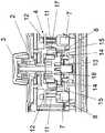
图2示出了图1中的调节元件的剖视图,Figure 2 shows a sectional view of the adjustment element of Figure 1,
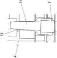
图3a示出了图2中的局部细节,其中,手柄位于中性位置中,Figure 3a shows a detail from figure 2 with the handle in the neutral position,
图3b示出了根据图3a的局部细节,其中,手柄位于移动位置中,Fig. 3b shows a partial detail according to Fig. 3a, wherein the handle is in the moving position,
图4示出了图1中的调节元件的另一剖视图,FIG. 4 shows another cross-sectional view of the adjustment element from FIG. 1 ,
图5a示出了用于图4中的调节元件的、由定子和转子构成的转动器件作为单个部件,Figure 5a shows the rotating means consisting of a stator and a rotor for the adjustment element of Figure 4 as a single part,
图5b示出了图5a中的转子作为单个部件的透视图,Figure 5b shows a perspective view of the rotor of Figure 5a as a single part,
图5c示出了图5a中的转子和定子的单个部件的原理示意图,Figure 5c shows a schematic diagram of the individual components of the rotor and stator of Figure 5a,
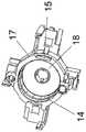
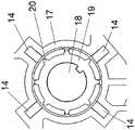
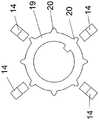
图6a根据另一实施方式示出了用于图4中的调节元件的、由定子和转子构成的转动器件作为单个部件,以及Fig. 6a shows, according to another embodiment, the rotating means consisting of a stator and a rotor for the adjusting element of Fig. 4 as a single part, and
图6b示出了图6a中的转子和定子的单个部件的原理示意图。Figure 6b shows a schematic diagram of the individual components of the rotor and stator of Figure 6a.
具体实施方式Detailed ways
在图1中可看见调节元件1,调节元件用于手动地操控和/或触发机动车中的功能。例如,调节元件1可为位于机动车的驾驶员侧的侧门中的门操作单元,使用者借助门操作单元可通过电动机调节机动车的外后视镜。In FIG. 1 an adjusting
调节元件1具有壳体2,手柄3从壳体2伸出使得使用者能手动地接触到。能以手动方式运动的手柄3与图2中示出的移动器件4共同作用,使得手柄3在移动平面中能够沿至少一个方向5从中性位置移动到移动位置中。在此,手柄3可沿基本上垂直于方向5的另一方向6运动到其他移动位置中,如根据图1所见。The
如还在图2中可见,设有用于调节元件1的磁体7和能磁化的元件8。磁体7与能磁化的元件8共同作用,使得在移动器件4移动时,磁体7和能磁化的元件8之间的磁力朝手柄3的移动位置的方向上产生触觉。换句话说,使用者必须克服磁体7和能磁化的元件8之间在中性位置中作用的磁力以使手柄3运动到移动位置中,这被使用者感知为触觉并且特别符合人体工程学。此外,在手柄3位于移动位置中时,磁力用作中性位置的方向5、6上的复位力,使得手柄3被使用者松开后自动地回到中性位置中。As can also be seen in FIG. 2 , a
移动器件4在移动位置中作用到图4中仅示意性示出的电开关元件9上。开关元件9布置在位于壳体2中的电路板10上。然后开关元件9在移动位置中产生开关信号形式的电信号。而该信号之后用于操控和/或触发机动车中的对应功能,例如用于操控电动机将外后视镜朝相应的方向调节。也可使用传感器等来代替开关元件9产生开关信号。In the displacement position, the displacement means 4 act on the
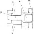
如根据图2可见,移动器件4构造成滑移件的形式。挺杆11能运动地支承在滑移件4中。磁体7面对能磁化的元件8地布置在挺杆 11中。确切地说,磁体7在挺杆11的下端固紧在挺杆11中,使得磁体7稍微从挺杆11中伸出。磁体7的伸出部分贴靠在能磁化的元件8上。此外,挺杆11以另一端、即上端能倾斜地保持在移动器件 4的开口12中。如果移动器件4借助手柄3从图3a中可见的中性位置运动到移动位置中,则挺杆11以其上端关于开口12倾斜,如在图 3b中所见。同时挺杆11的下端在能磁化的元件8上运动,其中,如前所述地在产生触觉的情况下必须克服磁力。As can be seen from FIG. 2 , the moving
如在图2中可见,磁体7构造成具有矩形横截面的棱柱形。优选地,磁体7构造成具有正方形横截面的立方体。能磁化的元件8构造成条形板。此外,移动器件4关于手柄3对称地构造,使得在图2中手柄3的左侧以及右侧分别有具有磁体7的挺杆11和能磁化的元件 8,由此在手柄3移动时实现特别符合人体工程学的触觉。尤其基于磁体7的矩形横截面,可在两个彼此垂直的方向5、6上产生触觉和/ 或复位力以使手柄3运动。为了防止外部影响,使能运动的移动器件 4位于壳体2的内部。而能磁化的元件8不可运动地布置在壳体2的内部。As can be seen in FIG. 2 , the
作为对可移动性的替代或补充,手柄3也可构造成能转动的。对此,为手柄3设置位于壳体2的内部的转动器件13。在手柄3除了可移动性外还具有可转动性的情况下,将转动器件13的至少一部分布置在移动器件4上,如在图4中可见。换句话说,转动器件13在此情况下是集成在移动器件4中。在手柄3构造成仅能转动的情况下取消移动器件4,或在手柄3构造成仅能移动的情况下取消转动器件 13。Alternatively or in addition to the movability, the
下面将根据图4详细地描述用于手动地操控和/或触发机动车中的功能的、作为呈转轮编码器形式的旋转编码器的调节元件1。在此,调节元件1的手柄3能借助转动器件13沿转动方向16(参见图1) 手动地转动。在此,手柄3与转动器件13共同作用,使得手柄3能转动到锁止位置形式的至少一个转动位置中。优选地,手柄3能转动到多个彼此接续的转动位置中。The adjusting
为了形成转动器件13,设有磁体14以及另一磁体15。也可设置能磁化的元件以代替另一磁体15或作为其补充,但是这在此没有进一步示出。磁体14与另一磁体15共同作用或者磁体14与能磁化的元件共同作用,使得磁体14和另一磁体15之间的磁力或磁体14和能磁化的元件之间的磁力在转动器件13转动时产生沿转动方向16的触觉和/或产生转动位置上对手柄3的锁止力。转动器件13在转动位置中沿转动方向16转动时作用到仅示意性示出的电开关元件9、传感器等上以产生信号。该信号此后以开关信号的形式用于操控和/或触发机动车中的对应功能,例如用于选择相应的外后视镜。To form the rotating
转动器件13包括定子17和能转动地布置在定子17上的转子18。转子18与手柄3连接。磁体14布置在转子18上并且另一磁体15布置在定子17上。或者,磁体14布置在转子18上并且能磁化的元件布置在定子17上,或者,能磁化的元件布置在转子18上并且磁体 14布置在定子17上。此外,在第一设计方案中,磁体14和/或另一磁体15构造成具有彼此交替布置的磁极的环形,如在图5c中原理性示出地。在此,磁体14以及另一磁体15彼此同心地布置。磁体14 在转子18上的更详细的布置方式在图5b中示出。最后,在图5a中可看见转子18和定子17与磁体14、15结合的更详细的设计方案。The
在另一设计方案、即第二设计方案中,多个磁体14呈圆形地布置在定子17上,如在图6a中可见。能磁化的元件19固定在与手柄 3连接的转子18上并且布置在定子17内。如还根据图6b可见,磁体14基本彼此均匀地间隔开。磁体14的同名磁极面对能磁化的元件 19地布置。能磁化的元件19构造成环形并且具有面对磁体14的齿 20。齿20的数量相应于能转动的手柄3的锁止位置的数量。In a further configuration, namely the second configuration, a plurality of
本实用新型不限于所述和示出的实施例。而是也可包括权利要求限定的实用新型内容中的所有技术改进方案。除了机动车应用外,这种调节元件1也可有利地用作计算机、工具机、家用电器等的输入器件。The invention is not limited to the embodiments described and shown. Instead, it can also include all technical improvements in the content of the utility model defined in the claims. In addition to motor vehicle applications, such an
附图标记列表:List of reference numerals:
1:调节元件1: Adjustment element
2:壳体2: Shell
3:手柄3: handle
4:移动器件4: Mobile Devices
5、6:(手柄移动的)方向5, 6: (the direction of the handle movement)
7:(用于移动器件的)磁体7: Magnets (for mobile devices)
8:(用于移动器件的)能磁化的元件8: Elements (for mobile devices) that can be magnetized
9:开关元件9: Switching element
10:电路板10: circuit board
11:挺杆11: Tappet
12:(移动器件中的)开口12: Openings (in mobile devices)
13:转动器件13: Turn the device
14:(用于转动器件的)磁体14: Magnets (for rotating devices)
15:(用于转动器件的)(另一)磁体15: (Another) Magnet (for rotating the device)
16:转动方向16: Rotation direction
17:定子17: Stator
18:转子18: Rotor
19:(用于转动器件的)能磁化的元件19: Magnetizable elements (for rotating devices)
20:(能磁化的元件上的)齿。20: Teeth (on a magnetizable element).
Claims (15)
Applications Claiming Priority (3)
| Application Number | Priority Date | Filing Date | Title |
|---|---|---|---|
| DE102019007986.8 | 2019-11-18 | ||
| DE102019007986.8ADE102019007986A1 (en) | 2019-11-18 | 2019-11-18 | Actuator, in particular for a motor vehicle |
| PCT/EP2020/081063WO2021099126A1 (en) | 2019-11-18 | 2020-11-05 | Actuator, in particular for a motor vehicle |
Publications (1)
| Publication Number | Publication Date |
|---|---|
| CN217279393Utrue CN217279393U (en) | 2022-08-23 |
Family
ID=73172674
Family Applications (1)
| Application Number | Title | Priority Date | Filing Date |
|---|---|---|---|
| CN202090000541.3UActiveCN217279393U (en) | 2019-11-18 | 2020-11-05 | Adjusting element |
Country Status (4)
| Country | Link |
|---|---|
| EP (1) | EP3914988B1 (en) |
| CN (1) | CN217279393U (en) |
| DE (1) | DE102019007986A1 (en) |
| WO (1) | WO2021099126A1 (en) |
Family Cites Families (7)
| Publication number | Priority date | Publication date | Assignee | Title |
|---|---|---|---|---|
| US7038667B1 (en)* | 1998-10-26 | 2006-05-02 | Immersion Corporation | Mechanisms for control knobs and other interface devices |
| DE10031096C2 (en)* | 2000-06-30 | 2002-04-25 | A B Elektronik Gmbh | Selection switching device |
| DE102004038311A1 (en)* | 2003-08-08 | 2005-03-10 | Marquardt Gmbh | Electronic switch, especially of joystick or cursor switch type, e.g. for motor vehicle use, has an activation element and rotating means including an outer rotor electric motor, which provide haptic feedback to the user |
| JP2007004705A (en)* | 2005-06-27 | 2007-01-11 | Mitsumi Electric Co Ltd | Joy stick device |
| JP2012066666A (en)* | 2010-09-22 | 2012-04-05 | Tokai Rika Co Ltd | Shift device |
| JP6098438B2 (en)* | 2013-08-27 | 2017-03-22 | 株式会社デンソー | Operating device |
| DE102014001630B4 (en)* | 2014-02-07 | 2019-03-21 | Audi Ag | Operating device and vehicle with operating device |
- 2019
- 2019-11-18DEDE102019007986.8Apatent/DE102019007986A1/enactivePending
- 2020
- 2020-11-05CNCN202090000541.3Upatent/CN217279393U/enactiveActive
- 2020-11-05WOPCT/EP2020/081063patent/WO2021099126A1/ennot_activeCeased
- 2020-11-05EPEP20803482.7Apatent/EP3914988B1/enactiveActive
Also Published As
| Publication number | Publication date |
|---|---|
| WO2021099126A1 (en) | 2021-05-27 |
| DE102019007986A1 (en) | 2021-05-20 |
| EP3914988A1 (en) | 2021-12-01 |
| EP3914988B1 (en) | 2025-08-13 |
Similar Documents
| Publication | Publication Date | Title |
|---|---|---|
| CN101223618B (en) | Control buttons with integrated functions | |
| US7242390B2 (en) | Electric switch | |
| US9793076B2 (en) | Switching operating arrangement | |
| KR960008882A (en) | Rotary switch and multi-directional input device | |
| US20090273423A1 (en) | Rotary actuator with magnetically generated haptics | |
| JP2006260179A (en) | Trackball equipment | |
| CN101534114B (en) | Rotationally-operated input device | |
| CN110914791A (en) | Operating device for operating a touch-sensitive surface of a vehicle, surface operating device having an operating device, and method and control unit for operating a touch-sensitive surface by means of an operating device | |
| US9811162B2 (en) | Operating device | |
| JP2002373055A (en) | Electronics | |
| JPH11249753A (en) | Multi-function joystick device | |
| CN217279393U (en) | Adjusting element | |
| CN217085611U (en) | Adjusting element, in particular for a motor vehicle | |
| CN1233007C (en) | Multii-directional input device | |
| JP2942098B2 (en) | Multi-directional input device | |
| JP3763044B2 (en) | Multi-directional switch | |
| JP4496921B2 (en) | Trackball equipment | |
| JP2002189559A (en) | Manual input device and on-vehicle equipment controller using the device | |
| JP3931532B2 (en) | Multi-directional electronic component and electronic equipment using the same | |
| JP2006286328A (en) | Composite operation type input device | |
| EP3214632B1 (en) | Multidirectional input device | |
| JP3701861B2 (en) | Encoder | |
| JP2004082327A (en) | Power tool | |
| JP7389540B1 (en) | Push-button switch | |
| JP2008269802A (en) | Input device |
Legal Events
| Date | Code | Title | Description |
|---|---|---|---|
| GR01 | Patent grant | ||
| GR01 | Patent grant |