CN217244557U - An anorectal surgical expansion rack - Google Patents
An anorectal surgical expansion rackDownload PDFInfo
- Publication number
- CN217244557U CN217244557UCN202220304244.9UCN202220304244UCN217244557UCN 217244557 UCN217244557 UCN 217244557UCN 202220304244 UCN202220304244 UCN 202220304244UCN 217244557 UCN217244557 UCN 217244557U
- Authority
- CN
- China
- Prior art keywords
- shells
- hinged
- base
- casing
- screw
- Prior art date
- Legal status (The legal status is an assumption and is not a legal conclusion. Google has not performed a legal analysis and makes no representation as to the accuracy of the status listed.)
- Active
Links
- 238000001356surgical procedureMethods0.000claimsabstractdescription14
- 210000000436anusAnatomy0.000description7
- 238000000034methodMethods0.000description3
- 208000015815Rectal diseaseDiseases0.000description2
- 210000001519tissueAnatomy0.000description2
- 238000003466weldingMethods0.000description2
- 206010028980NeoplasmDiseases0.000description1
- 230000009286beneficial effectEffects0.000description1
- 210000001217buttockAnatomy0.000description1
- 230000007812deficiencyEffects0.000description1
- 238000010586diagramMethods0.000description1
- 201000010099diseaseDiseases0.000description1
- 208000037265diseases, disorders, signs and symptomsDiseases0.000description1
- 208000014674injuryDiseases0.000description1
- 210000002429large intestineAnatomy0.000description1
- 239000000314lubricantSubstances0.000description1
- 238000004519manufacturing processMethods0.000description1
- 230000004048modificationEffects0.000description1
- 238000012986modificationMethods0.000description1
- 210000003205muscleAnatomy0.000description1
- 230000008733traumaEffects0.000description1
- 230000000007visual effectEffects0.000description1
Images


Landscapes
- Surgical Instruments (AREA)
Abstract
Translated fromChinese
Description
Translated fromChinese技术领域technical field
本实用新型属于医疗器具领域,尤其是涉及一种肛肠外科手术扩张架。The utility model belongs to the field of medical appliances, in particular to an expansion rack for anorectal surgery.
背景技术Background technique
肛肠外科是以手术为主要方法治疗发生于肛门和大肠部位的肿瘤、外伤及其他疾病的临床学科,肛肠疾病以发生在肛门直肠肠段最多见,肛肠疾病的手术治疗常用扩张器对肛肠进行扩张,从外部使用手术器械进行手术,充分的对肛门内部进行视野的暴露,有助于医护人员进行手术的操作。Anorectal surgery is a clinical discipline that treats tumors, trauma and other diseases that occur in the anus and large intestine with surgery as the main method. Anorectal diseases are most common in the anorectal segment. The surgical treatment of anorectal diseases often uses dilators to dilate the anorectum. , Use surgical instruments from the outside to perform surgery, and fully expose the visual field of the inside of the anus, which is helpful for medical staff to perform surgery.
但是现有的扩张架,使用时对肛肠内部暴露不够充分,使得医生在进行手术操作时可直接观察的区域少,在一定程度上影响了医生的判断力。However, the existing expansion frame does not sufficiently expose the interior of the anorectum during use, so that the area that the doctor can directly observe during the surgical operation is small, which affects the doctor's judgment to a certain extent.
实用新型内容Utility model content
根据以上现有技术中的不足,本实用新型要解决的技术问题是:提供一种肛肠外科手术扩张架,能够最大程度的对肛肠进行暴露,方便医生的判断和操作,加快手术进程。According to the above deficiencies in the prior art, the technical problem to be solved by the present invention is to provide an anorectal surgical expansion frame, which can expose the anorectum to the greatest extent, facilitate the judgment and operation of the doctor, and speed up the operation process.
所述的肛肠外科手术扩张架,包括环状的底座,所述底座的上方竖直设置有两块呈夹持配合的外壳,两块外壳的下端铰接在底座的顶部,外壳呈夹持状态时呈圆锥状,两块外壳之间设置有用于调节外壳夹持角度的调节组件。The expansion frame for anorectal surgery includes a ring-shaped base, two outer shells that are clamped and matched are vertically arranged above the base, and the lower ends of the two outer shells are hinged on the top of the base. It is in the shape of a cone, and an adjustment component for adjusting the clamping angle of the shells is arranged between the two shells.
进一步的,所述调节组件包括两根自由旋转的螺杆,两根螺杆呈前后分布且竖直设置在两块外壳之间,每根螺杆上端均安装有支撑板,螺杆与支撑板呈只做旋转配合的活动连接,每块支撑板均通过固定组件连接在底座上,每根螺杆上均套装有与之呈螺纹配合的螺母,螺母的左右两侧均铰接有连杆,左侧连杆的活动端铰接在左侧外壳的内侧壁上,右侧连杆的活动端铰接在右侧外壳的内侧壁上。Further, the adjustment assembly includes two freely rotating screws, the two screws are distributed back and forth and are vertically arranged between the two shells, and a support plate is installed on the upper end of each screw, and the screw and the support plate are only rotated. Matching movable connection, each support plate is connected to the base through a fixed component, each screw is sleeved with a nut that is threaded with it, the left and right sides of the nut are hinged with connecting rods, and the movement of the left connecting rod The end is hinged on the inner side wall of the left casing, and the active end of the right link is hinged on the inner side wall of the right casing.
进一步的,所述固定组件为竖直设置的连接板,连接板的上端与支撑板固定,连接板的下端固定在底座上。Further, the fixing component is a vertically arranged connecting plate, the upper end of the connecting plate is fixed with the support plate, and the lower end of the connecting plate is fixed on the base.
进一步的,所述螺杆的底部开设有用于方便旋转螺杆的多边形凹槽。Further, the bottom of the screw is provided with a polygonal groove for convenient rotation of the screw.
进一步的,所述螺母为六角螺母。Further, the nut is a hexagonal nut.
进一步的,所述外壳与每根连杆的铰接处均设置有固定块,连杆铰接在固定块上,固定块固定在外壳的内侧壁上。Further, a fixing block is provided at the hinge joint between the casing and each connecting rod, the connecting rod is hinged on the fixing block, and the fixing block is fixed on the inner side wall of the casing.
进一步的,所述外壳下端的外侧壁向内凹陷。Further, the outer side wall of the lower end of the casing is recessed inward.
与现有技术相比,本实用新型具有以下有益效果:Compared with the prior art, the utility model has the following beneficial effects:
本实用新型利用先插入再扩张的方式对肛肠进行充分的暴露,扩张的大小能够自由调节,使用起来更加方便,医生不需要反复摇晃灯光去观察肛肠内部情况,加快手术的进度,降低风险。The utility model fully exposes the anorectum by inserting first and then expanding, the size of the expansion can be adjusted freely, and it is more convenient to use, the doctor does not need to shake the light repeatedly to observe the internal situation of the anorectum, which speeds up the progress of the operation and reduces the risk.
附图说明Description of drawings
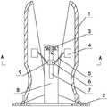
图1为本实用新型的结构示意图;Fig. 1 is the structural representation of the utility model;
图2为图1的俯视图;Fig. 2 is the top view of Fig. 1;
图3为本实用新型的使用状态图;Fig. 3 is the use state diagram of the present utility model;
图4为图3中A-A处的剖视图;Fig. 4 is the sectional view at A-A place in Fig. 3;
图5为图4中B处的放大图;Fig. 5 is the enlarged view of B place in Fig. 4;
图6为图4中支撑板的结构示意图;Fig. 6 is the structural representation of the support plate in Fig. 4;
图中各部件名称:1、外壳2、底座3、支撑板4、固定块5、连杆6、螺母7、螺杆8、连接板9、连接块。The names of the components in the figure: 1.
具体实施方式Detailed ways
以下结合附图通过具体实施例对本实用新型作进一步说明,但不用以限制本实用新型,凡在本实用新型精神和原则之内,所作的任何修改、等同替换、改进等,均应包含在本发明的保护范围之内。Below in conjunction with the accompanying drawings, the present utility model will be further described by specific embodiments, but it is not intended to limit the present utility model. Any modification, equivalent replacement, improvement, etc. made within the spirit and principle of the present utility model shall be included in the present utility model. within the scope of protection of the invention.
实施例1Example 1
本实施例所述的一种肛肠外科手术扩张架,包括环状的底座2,所述底座2的上方竖直设置有两块呈夹持配合的外壳1,两块外壳1的下端铰接在底座2的顶部,外壳1呈夹持状态时呈圆锥状,如图1和图2所示,两块外壳1左右对称,外壳1下端的外侧壁与底座2的顶部通过合页铰接在一起,两块外壳1相互夹持时呈圆锥状,顶部倒圆角处理,防止使用时损伤肛肠内部组织;底座2中间的通孔用于医疗器具的通过;An anorectal surgical expansion frame described in this embodiment includes a ring-
两块外壳1之间设置有用于调节外壳1夹持角度的调节组件,调节组件调节左右两块外壳1的夹持角度,使得肛门被撑开,肛肠内部情况被充分暴露在医生的视野内。An adjustment component for adjusting the clamping angle of the
本实施例使用时,在外壳1上均匀涂抹好医用润滑剂,然后将外壳1插入患者肛门中,底座2紧贴臀部,为预防外壳1滑出,可以在底座2上固定绑带,绑带缠绕在患者身上,然后通过调节组件自由调节外壳1的夹持角度,使外壳1将肛肠内部撑开到合适医生手术的位置。When using this embodiment, evenly spread the medical lubricant on the
实施例2Example 2
本实施例将技术进一步进行说明,所述调节组件包括两根自由旋转的螺杆7,两根螺杆7呈前后分布且竖直设置在两块外壳1之间,每根螺杆7上端均安装有支撑板3,螺杆7与支撑板3呈只做旋转配合的活动连接,每块支撑板3均通过固定组件连接在底座2上,支撑板3用于支撑螺杆7,并固定其的位置,使得螺杆7只旋转而不上下移动,螺杆7的上端通过轴承安装在支撑板3上,支撑板3的底部开设有用于安装轴承的安装槽,轴承的外圈与安装槽的槽壁过盈配合,轴承的内圈与螺杆7上端的侧壁过盈配合;在实际应用时,还可以在螺杆7的顶部焊接一块圆盘状的固定件,用于对螺杆7进行限位,同时在支撑板3内开设用于固定件旋转的空腔;This embodiment will further illustrate the technology. The adjustment assembly includes two freely rotating
每根螺杆7上均套装有与之呈螺纹配合的螺母6,当旋转螺杆7时,螺母6沿螺杆7上下移动;Each
螺母6的左右两侧均铰接有连杆5,左侧连杆5的活动端铰接在左侧外壳1的内侧壁上,右侧连杆5的活动端铰接在右侧外壳1的内侧壁上,如图3、图4和图5所示,螺母6的左侧固定有连接块9,连接块9铰接有连杆5的一端,连杆5的另一端通过连接块9铰接在左侧外壳1的内侧壁上;螺母6的右侧固定有连接块9,连接块9铰接有连杆5的一端,连杆5的另一端通过连接块9铰接在右侧外壳1的内侧壁上;The left and right sides of the
本实施例使用时,如图1所示,为外壳1的初始状态,整体呈圆锥状,当顺时针旋转螺杆7时,螺母6向上移动,螺母6与外壳1都有两个铰接点的情况下,连杆5的倾斜角度逐渐变大,因连杆5的长度不变,右侧的连杆5会推动右侧的外壳1顺时针绕外壳1与底座2的铰接点旋转,左侧的连杆5会推动左侧的外壳1逆时针绕外壳1与底座2的铰接点旋转,外壳1在旋转的过程中逐渐撑开肛肠,使肛肠内部情况充分暴露在医生的视野之下,手术完成后,逆时针旋转螺杆7使外壳1恢复到初始状态,再取出外壳1。When this embodiment is used, as shown in Figure 1, it is the initial state of the
在实际应用时,调节组件还可以是设置在外壳1内的环形气囊,通过充放气来控制外壳1的张开或合拢。In practical application, the adjustment component may also be an annular air bag disposed in the
实施例3Example 3
本实施例将技术进一步进行说明,所述固定组件为竖直设置的连接板8,连接板8的上端与支撑板3固定,连接板8的下端固定在底座2上,连接板8通过焊接的方式固定在底座2的顶部,如图3、图4和图5所示,前侧连接板8的后侧面与支撑板3通过螺钉固定,后侧连接板8的前侧面与支撑板3通过螺钉固定;This embodiment will further illustrate the technology, the fixing component is a vertically arranged connecting
本实施例在实际应用时,固定组件还可以是连接杆。In practical application of this embodiment, the fixing component may also be a connecting rod.
实施例4Example 4
本实施例将技术进一步进行说明,所述螺杆7的底部开设有用于方便旋转螺杆7的多边形凹槽,如矩形凹槽、正六边形凹槽等,使用时通过与之对应的医用螺丝刀,将其刀头插入凹槽内,继而驱动螺杆7旋转使螺母6上下移动,从而带动外壳1张开或合拢。This embodiment will further illustrate the technology. The bottom of the
本实施例在实际应用时,也可以使螺杆7靠近底座2的一端向下延伸至底座2的下方,使用使直接旋转螺杆7带动外壳1张开或合拢。In practical application of this embodiment, the end of the
实施例5Example 5
本实施例将技术进一步进行说明,所述螺母6为六角螺母,便于对连接块9进行焊接,减小制作连接块9时的工艺要求。This embodiment will further illustrate the technology. The
实施例6Example 6
本实施例将技术进一步进行说明,所述外壳1与每根连杆5的铰接处均设置有固定块4,连杆5铰接在固定块4上,固定块4固定在外壳1的内侧壁上,固定块4用于方便对连接块9的固定,减小制作连接块9的工艺要求,如图4所示,连杆5通过连接块9铰接在固定块4上,连接块9焊接在固定块4上,固定块4焊接在外壳1的内侧壁上。This embodiment will further illustrate the technology. A fixing
实施例7Example 7
本实施例将技术进一步进行说明,所述外壳1下端的外侧壁向内凹陷,由于外壳1在插入患者肛门后,会收到肛门内肌肉、肛肠组织等的排挤,会有向外滑出的趋势,而在外壳1下端的外侧壁设置成向内凹陷的结构便于插入患者肛门内后,肛门口的肌肉刚好卡在凹陷处,防止外壳1向外滑出。This embodiment will further illustrate the technology. The outer side wall of the lower end of the
Claims (7)
Translated fromChinesePriority Applications (1)
| Application Number | Priority Date | Filing Date | Title |
|---|---|---|---|
| CN202220304244.9UCN217244557U (en) | 2022-02-15 | 2022-02-15 | An anorectal surgical expansion rack |
Applications Claiming Priority (1)
| Application Number | Priority Date | Filing Date | Title |
|---|---|---|---|
| CN202220304244.9UCN217244557U (en) | 2022-02-15 | 2022-02-15 | An anorectal surgical expansion rack |
Publications (1)
| Publication Number | Publication Date |
|---|---|
| CN217244557Utrue CN217244557U (en) | 2022-08-23 |
Family
ID=82855180
Family Applications (1)
| Application Number | Title | Priority Date | Filing Date |
|---|---|---|---|
| CN202220304244.9UActiveCN217244557U (en) | 2022-02-15 | 2022-02-15 | An anorectal surgical expansion rack |
Country Status (1)
| Country | Link |
|---|---|
| CN (1) | CN217244557U (en) |
- 2022
- 2022-02-15CNCN202220304244.9Upatent/CN217244557U/enactiveActive
Similar Documents
| Publication | Publication Date | Title |
|---|---|---|
| WO2020199307A1 (en) | Hollow, vectorial, and supportive multi-functional protection device for minimally invasive surgery | |
| CN106137529B (en) | Open eyelid and eyeball fixture | |
| CN217244557U (en) | An anorectal surgical expansion rack | |
| CN109172130B (en) | Medical robot for myopia operation | |
| CN112274198A (en) | Laparoscope shielding device and working method thereof | |
| CN113116418A (en) | Surgery wound strutting arrangement | |
| CN113081100A (en) | Convenient-to-use eyelid retractor for medical ophthalmology | |
| CN209332264U (en) | Auxiliary body applied to medical robot | |
| CN106618648A (en) | Minitype universal surgical drag hook | |
| CN217244555U (en) | A dilation device that exposes the depths of the surgical approach | |
| CN213758384U (en) | A surgical incision opener | |
| CN211704954U (en) | Small-opening scar contracture orthosis | |
| CN113598852A (en) | Cervical dilator for gynecological operation | |
| CN114909622A (en) | Nursing lamp for operating room based on lamp bead position adjustment mechanism | |
| CN114795332A (en) | Heart operation wound supports dodges ware | |
| CN209770443U (en) | Thoracic surgery chest cavity opening device | |
| CN215534251U (en) | Vaginal dilator capable of preventing vaginal injury | |
| CN221865632U (en) | Auxiliary fixation device for ophthalmic examination | |
| CN114129204A (en) | Shoulder arthroscope minimally invasive surgery traction device | |
| CN114176976A (en) | An adjustable head immobilization device for ophthalmic surgery | |
| CN109394283B (en) | Dilating forceps for gynecological operation | |
| CN111248845A (en) | Expandable support laryngoscope | |
| CN215534253U (en) | Vaginal dilator with wing | |
| CN206214132U (en) | Laparoscopic surgery exempts from pneumoperitoneum drag hook | |
| CN223403841U (en) | A vaginal dilator |
Legal Events
| Date | Code | Title | Description |
|---|---|---|---|
| GR01 | Patent grant | ||
| GR01 | Patent grant |