CN217244555U - A dilation device that exposes the depths of the surgical approach - Google Patents
A dilation device that exposes the depths of the surgical approachDownload PDFInfo
- Publication number
- CN217244555U CN217244555UCN202220129639.XUCN202220129639UCN217244555UCN 217244555 UCN217244555 UCN 217244555UCN 202220129639 UCN202220129639 UCN 202220129639UCN 217244555 UCN217244555 UCN 217244555U
- Authority
- CN
- China
- Prior art keywords
- expansion
- fixing mechanism
- surgical approach
- depth
- exposing
- Prior art date
- Legal status (The legal status is an assumption and is not a legal conclusion. Google has not performed a legal analysis and makes no representation as to the accuracy of the status listed.)
- Expired - Fee Related
Links
- 238000013459approachMethods0.000titleclaimsabstractdescription81
- 230000010339dilationEffects0.000titledescription7
- 230000007246mechanismEffects0.000claimsabstractdescription214
- 238000009434installationMethods0.000claimsdescription8
- 238000000926separation methodMethods0.000claimsdescription2
- 210000000436anusAnatomy0.000abstractdescription15
- 230000008901benefitEffects0.000abstractdescription4
- 201000010099diseaseDiseases0.000abstractdescription3
- 208000037265diseases, disorders, signs and symptomsDiseases0.000abstractdescription3
- 230000009286beneficial effectEffects0.000abstractdescription2
- 230000000007visual effectEffects0.000abstractdescription2
- 238000010586diagramMethods0.000description14
- 238000000034methodMethods0.000description5
- 238000007689inspectionMethods0.000description4
- 230000000968intestinal effectEffects0.000description4
- 238000001356surgical procedureMethods0.000description4
- 238000005286illuminationMethods0.000description3
- 208000004680Rectal FistulaDiseases0.000description2
- 230000009471actionEffects0.000description2
- 206010002156anal fistulaDiseases0.000description2
- 238000013016dampingMethods0.000description2
- 230000000694effectsEffects0.000description2
- 230000008569processEffects0.000description2
- 210000005070sphincterAnatomy0.000description2
- 239000013589supplementSubstances0.000description2
- 230000007704transitionEffects0.000description2
- 208000002847Surgical WoundDiseases0.000description1
- 230000015572biosynthetic processEffects0.000description1
- 230000000903blocking effectEffects0.000description1
- 210000001217buttockAnatomy0.000description1
- 230000008859changeEffects0.000description1
- 238000010276constructionMethods0.000description1
- 230000001276controlling effectEffects0.000description1
- 238000006073displacement reactionMethods0.000description1
- 238000000605extractionMethods0.000description1
- 210000001035gastrointestinal tractAnatomy0.000description1
- 239000003292glueSubstances0.000description1
- 239000000463materialSubstances0.000description1
- 238000012986modificationMethods0.000description1
- 230000004048modificationEffects0.000description1
- 238000006116polymerization reactionMethods0.000description1
- 230000008092positive effectEffects0.000description1
- 230000001105regulatory effectEffects0.000description1
- 238000002271resectionMethods0.000description1
- 230000000087stabilizing effectEffects0.000description1
- 238000011477surgical interventionMethods0.000description1
Images


Landscapes
- Surgical Instruments (AREA)
Abstract
Description
Translated fromChinese技术领域technical field
本实用新型专利属于肛门镜领域,具体地说,是一种暴露手术入路深处的扩张装置。The utility model patent belongs to the field of anoscope, in particular, it is an expansion device for exposing the depth of a surgical approach.
背景技术Background technique
现有的肛门部手术辅助扩展装置基本局限于肛内,如肛门镜之类无法适用于肛外入路,且需要助手辅助固定,操作不便;常见的肛门部手术辅助牵开装置可适用于肛内和肛外入路手术,但由于其自固定于臀部,撑开角度调节不便,且仅能做表层牵开,无法充分暴露深部,而传统肛瘘切开术、肛瘘切除术等是为了打开术野往往采取切除组织的方法逐渐脱离时代审美及要求,同时给患者造成了额外的伤害。Existing auxiliary expansion devices for anal surgery are basically limited to the inside of the anus, such as anoscope, which cannot be applied to the extra-anal approach, and require assistants to assist fixation, which is inconvenient to operate; common auxiliary retraction devices for anal surgery can be applied to the anus. Internal and extra-anal approach surgery, but because of its self-fixation on the buttocks, it is inconvenient to adjust the opening angle, and it can only do superficial retraction, which cannot fully expose the deep part, while traditional anal fistula incision, anal fistula resection, etc. are for opening surgery Wild often adopts the method of excision of tissue to gradually break away from the aesthetics and requirements of the times, and at the same time causes additional harm to patients.
中国专利文献CN210138129U公开了一种带有冷光照明的肛门镜组件,由外向内分别由固定器,检查镜筒和扩张器套接组成,固定器由一体成型的管状固定管和环状固定环组成,检查镜筒包括一体成型的镜筒体和外把手组成,镜筒体两端直径不同,镜筒体轴向开口形成视窗,外把手设置在镜筒体直径大的一端,镜筒体内设有照明灯,外把手外侧设有照明开关,照明灯和照明开关电连接,镜筒体内壁设有反光罩。其优点和积极效果是:镜筒体内设有LED灯,能够在检查过程中照明,使得使用者更清楚的观察肠壁,反光罩的设置,能够将光线聚集,使得照明效果更佳,在弧形的反光罩的作用下,能够最大限度的将光线聚集到视窗露出的肠壁上,有利于使用者做出精确的判断。显而易见的是,该技术方案解决的问题是对于肠壁的观察,缺点是,无法调整扩张尺度,不适用于沿括约肌间的手术入路。Chinese patent document CN210138129U discloses an anoscope assembly with cold light illumination, which is composed of a fixer, an inspection lens barrel and a dilator sleeve from the outside to the inside, and the fixer is composed of an integrally formed tubular fixing tube and an annular fixing ring. , the inspection lens barrel consists of an integrally formed lens barrel body and an outer handle. The diameters of the two ends of the lens barrel body are different. The axial opening of the lens barrel body forms a viewing window. The lighting lamp is provided with a lighting switch on the outside of the outer handle, the lighting lamp and the lighting switch are electrically connected, and a reflector is arranged on the inner wall of the lens barrel. Its advantages and positive effects are: LED lights are installed in the lens barrel, which can illuminate during the inspection process, so that the user can observe the intestinal wall more clearly, and the setting of the reflector can gather the light, so that the lighting effect is better. Under the action of the shaped reflector, the light can be gathered to the maximum extent on the intestinal wall exposed by the window, which is beneficial for the user to make accurate judgments. Obviously, the problem solved by this technical solution is the observation of the intestinal wall. The disadvantage is that the expansion scale cannot be adjusted, and it is not suitable for the surgical approach along the intersphincter.
中国专利文献CN204394456U公开了一种多功能医用扩肛器,用于扩张肛门,便于检查与治疗。其技术方案是:固定盘旋转连接在主螺杆的上端,扩张盘连接在主螺杆的下端,固定盘和扩张盘之间有多根扩张杆相连接。固定盘推入肛门后,转动主螺杆沿着固定盘的螺孔向前移动,主螺杆带动扩张盘同时向前移动,扩张盘将肛门扩张,同时通过冷光源可以进行照明,通过摄像头可以进行录像。本实用新型专利可以充分暴露患处,照明可以达到无影效果,摄像头可以现场传输图像。其缺点是,扩张盘尺寸大,不适用于肛门以外的手术入路,其摄像头及光源设于扩张盘下,用于探测扩张盘下的视野,阻碍了相关的手术介入,仅能实现肠道的检查,且其扩张范围受限于扩张盘的大小。Chinese patent document CN204394456U discloses a multifunctional medical anal expander, which is used to expand the anus and is convenient for inspection and treatment. The technical scheme is as follows: the fixed disk is rotatably connected to the upper end of the main screw rod, the expansion disk is connected to the lower end of the main screw rod, and a plurality of expansion rods are connected between the fixed disk and the expansion disk. After the fixed disk is pushed into the anus, rotate the main screw to move forward along the screw hole of the fixed disk. The main screw drives the expansion disk to move forward at the same time, and the expansion disk expands the anus. At the same time, the cold light source can be used for lighting, and the camera can record video. . The utility model patent can fully expose the affected area, the lighting can achieve shadowless effect, and the camera can transmit images on the spot. The disadvantage is that the size of the dilatation disc is large, and it is not suitable for surgical approaches other than the anus. The camera and light source are located under the dilatation disc to detect the field of view under the dilatation disc, which hinders the relevant surgical intervention, and can only achieve the intestinal tract. , and its expansion range is limited by the size of the expansion disc.
中国专利文献CN206587268U公开了一种一次性肛门扩张及取物套件,包括取便钳、肛门扩张器和扩张器内芯,肛门扩张器包括扩张器上叶和扩张器下叶,扩张器上叶和扩张器下叶上下对称设置并通过后部的销轴转动连接成一体;扩张器内芯包括内芯杆体,内芯杆体前端设有圆球形的内芯头端;在进行肛门扩张时,肛门扩张器的扩张器上叶和扩张器下叶构成的内腔中伸入扩张器内芯,扩张器内芯的内芯头端从肛门扩张器前端伸出;在进行肛门取便时,取便钳伸入肛门扩张器的扩张器上叶和扩张器下叶构成的内腔中。该专利方案中提供了扩张器上叶与扩张器下叶,通过扩张器上叶与扩张器下叶的相对开合,实现肛门的相对扩张,首先,其扩张有初始直径,因此需要内芯杆体用于过渡引导,同样其无法适用于没有原始通道的肌间入路。Chinese patent document CN206587268U discloses a disposable anal dilation and material extraction kit, which includes a stool removal forceps, an anal dilator and an inner core of the dilator. The anal dilator includes an upper lobe of the dilator and a lower lobe of the dilator. The lower leaf of the dilator is arranged symmetrically up and down and is connected into one body through the rotation of the rear pin shaft; the inner core of the dilator includes an inner core rod body, and the front end of the inner core rod body is provided with a spherical inner core head end; when the anus is expanded, the anus expands The inner cavity formed by the upper leaflet of the dilator and the lower leaflet of the dilator is inserted into the inner core of the dilator, and the head end of the inner core of the dilator core protrudes from the front end of the anal dilator; Extend into the lumen formed by the upper leaflet and lower leaflet of the anal dilator. In this patented solution, the upper leaflet of the dilator and the lower leaflet of the dilator are provided, and the relative expansion of the anus is realized by the relative opening and closing of the upper leaflet of the dilator and the lower leaflet of the dilator. First, the expansion has an initial diameter, so an inner core rod is required. Used for transition guidance, it also cannot be applied to the intermuscular approach without the original channel.
综上所述,亟需一种能调整手术入路视野深度、广度,且能充分暴露入路侧壁,利于找到病源,既适用于肛内入路又适用于肛外入路的暴露手术入路深处的扩张装置。To sum up, there is an urgent need for an exposure surgical approach that can adjust the depth and breadth of the surgical approach, and can fully expose the sidewall of the approach, which is conducive to finding the source of the disease, and is suitable for both intra-anal and extra-anal approaches. An expansion device deep in the road.
发明内容SUMMARY OF THE INVENTION
本实用新型专利的目的是,提供一种能调整手术入路视野深度、广度,且能充分暴露入路侧壁,利于找到病源,既适用于肛内入路又适用于肛外入路的暴露手术入路深处的扩张装置。The purpose of this utility model patent is to provide a method that can adjust the depth and breadth of the visual field of the surgical approach, and can fully expose the side wall of the approach, which is conducive to finding the source of the disease, and is suitable for exposure of both the intra-anal approach and the extra-anal approach. Dilation devices deep within the surgical approach.
为实现上述目的,本实用新型专利采取的技术方案是:In order to realize the above-mentioned purpose, the technical scheme that the utility model patent adopts is:
一种暴露手术入路深处的扩张装置,包括调节机构、固定机构、扩张机构;所述固定机构为中空环状结构,其上设有若干所述扩张机构,所述扩张机构与所述固定机构铰接,其中,若干所述扩张机构其一端可分离式相合;所述调节机构与所述固定机构活动套接,所述调节机构控制若干所述扩张机构之间的分离相合。An expansion device for exposing the depth of a surgical approach, comprising an adjustment mechanism, a fixing mechanism, and an expansion mechanism; the fixing mechanism is a hollow annular structure on which a plurality of the expansion mechanisms are arranged, and the expansion mechanism is connected with the fixing mechanism. The mechanism is hinged, wherein one end of a plurality of the expansion mechanisms is separably connected; the adjustment mechanism is movably sleeved with the fixing mechanism, and the adjustment mechanism controls the separation and engagement of the expansion mechanisms.
作为一种优选的技术方案,还包括限制机构,所述限制机构用于收紧分离的若干所述扩张机构。As a preferred technical solution, a restriction mechanism is also included, and the restriction mechanism is used for tightening the separated expansion mechanisms.
作为一种优选的技术方案,所述固定机构为圆环结构,对应的,所述调节机构亦为圆环结构;所述调节机构其外壁与所述固定机构其内壁螺纹连接。As a preferred technical solution, the fixing mechanism is a circular ring structure, and correspondingly, the adjusting mechanism is also a circular ring structure; the outer wall of the regulating mechanism is threadedly connected to the inner wall of the fixing mechanism.
作为一种优选的技术方案,所述扩张机构为条形结构;包括第一扩张段、第二扩张段;所述第一扩张段与所述第二扩张段呈一定角度,其中,所述第一扩张段与所述固定机构铰接;若干所述第二扩张段可聚合相贴。As a preferred technical solution, the expansion mechanism is a bar-shaped structure; it includes a first expansion section and a second expansion section; the first expansion section and the second expansion section are at a certain angle, wherein the first expansion section An expansion section is hingedly connected with the fixing mechanism; a plurality of the second expansion sections can be polymerized and attached to each other.
作为一种优选的技术方案,所述限制机构为弹性圈,所述弹性圈套在若干所述扩张机构上。As a preferred technical solution, the restricting mechanism is an elastic ring, and the elastic ring is sleeved on a plurality of the expansion mechanisms.
作为一种优选的技术方案,所述固定机构其上设有限制槽,所述弹性圈设于所述限制槽内。As a preferred technical solution, the fixing mechanism is provided with a restriction groove, and the elastic ring is arranged in the restriction groove.
作为一种优选的技术方案,所述扩张机构其上设有安装槽,所述弹性圈设于所述安装槽内。As a preferred technical solution, the expansion mechanism is provided with an installation groove, and the elastic ring is arranged in the installation groove.
作为一种优选的技术方案,所述固定机构其上设有手柄,所述调节机构其上设有照明装置。As a preferred technical solution, the fixing mechanism is provided with a handle, and the adjusting mechanism is provided with a lighting device.
作为一种优选的技术方案,所述扩张机构在与所述固定机构的铰接的另一端设有操纵杆,所述操纵杆用于控制与其相连的所述扩张机构的开合。As a preferred technical solution, the expansion mechanism is provided with a joystick at the other end of the hinged connection with the fixing mechanism, and the joystick is used to control the opening and closing of the expansion mechanism connected thereto.
作为一种优选的技术方案,所述固定机构为方形环状中空结构,其长边上设有若干扩张机构,所述调节机构与方形环状的固定机构相适配,所述调节机构与所述固定机构卡接固定。As a preferred technical solution, the fixing mechanism is a square ring-shaped hollow structure with several expansion mechanisms on the long sides, the adjusting mechanism is adapted to the square ring-shaped fixing mechanism, and the adjusting mechanism is compatible with the The fixing mechanism is clamped and fixed.
本实用新型专利优点在于:The advantages of this utility model patent are:
1、一种暴露手术入路深处的扩张装置,包括调节机构、固定机构、扩张机构;所述调节机构控制所述扩张机构的运动,所述固定机构为中空环状结构,其上设有若干所述扩张机构,所述扩张机构与所述固定机构铰接;若干所述扩张机构沿环状固定机构设置,可以从多角度打开手术入路,扩大视野范围。1. An expansion device for exposing the depth of a surgical approach, comprising an adjustment mechanism, a fixing mechanism, and an expansion mechanism; the adjustment mechanism controls the movement of the expansion mechanism, and the fixing mechanism is a hollow annular structure on which is arranged A plurality of the expansion mechanisms are hinged to the fixing mechanism; a plurality of the expansion mechanisms are arranged along the annular fixing mechanism, which can open the surgical approach from multiple angles and expand the field of vision.
2、若干所述扩张机构其一端可分离式相合;无需导引头,可以直接进入手术入路进行扩张。2. One end of several expansion mechanisms can be detachably connected; without the need for a guide head, the expansion mechanism can be directly entered into the surgical approach for expansion.
3、所述调节机构其上设有照明装置,可以聚焦扩张的手术入路,为手术视野提供照明。3. The adjusting mechanism is provided with an illumination device, which can focus on the expanded surgical approach and provide illumination for the surgical field of view.
4、所述固定机构为圆环结构,对应的,所述调节机构亦为圆环结构;其圆环结构方便所述扩张机构的均匀分布,进一步的使手术入路的扩张呈现圆形通道,适合小切口、小通道的手术入路扩张。4. The fixing mechanism is a ring structure, correspondingly, the adjusting mechanism is also a ring structure; the ring structure facilitates the even distribution of the expansion mechanism, and further makes the expansion of the surgical approach a circular channel, It is suitable for the expansion of surgical approach with small incision and small channel.
5、所述调节机构其外壁与所述固定机构其内壁螺纹连接,便于调节且稳定,所述调节机构其长度长于所述固定机构其长度,用于控制所述扩张机构的扩张。5. The outer wall of the adjusting mechanism is threadedly connected to the inner wall of the fixing mechanism, which is convenient and stable for adjustment. The length of the adjusting mechanism is longer than that of the fixing mechanism, and is used to control the expansion of the expansion mechanism.
6、所述扩张机构为条形结构;包括第一扩张段、第二扩张段;所述第一扩张段与所述第二扩张段呈一定角度,其中,所述第一扩张段与所述固定机构铰接;若干所述第二扩张段可聚合相贴;其中,所述第二扩张段聚合相贴,可自由深入小切口手术入路;所述第一扩张段与所述第二扩张段呈一定角度,其在扩张时,可使手术入路深处扩张的同时,而切口处保持相对较小的扩张,既扩大了手术入路深处的手术空间,又避免了入路切口的扩大。6. The expansion mechanism is a bar-shaped structure; it includes a first expansion section and a second expansion section; the first expansion section and the second expansion section are at a certain angle, wherein the first expansion section and the The fixing mechanism is hinged; a plurality of the second expansion sections can be attached to each other in a polymerized manner; wherein, the second expansion sections can be attached to each other through polymerization, and can be freely penetrated into the small incision surgical approach; the first expansion section and the second expansion section At a certain angle, when expanding, it can expand the depth of the surgical approach while maintaining a relatively small expansion at the incision, which not only expands the operating space in the depth of the surgical approach, but also avoids the expansion of the incision. .
7、所述固定机构其上设有手柄,便于握持;所述固定机构其上还设有支撑架,用于稳定手术入路通道。7. The fixing mechanism is provided with a handle, which is easy to hold; the fixing mechanism is also provided with a support frame for stabilizing the surgical access channel.
8、所述暴露手术入路深处的扩张装置包括限制机构,所述限制机构套在若干所述扩张机构上,在所述调节机构处于回缩的情况下,即所述扩张机构未扩张时,所述扩张机构在所述限制机构的作用下,可以保持聚拢的状态,方便手术入路的构建与撤出。8. The expansion device exposing the depth of the surgical approach includes a restriction mechanism, and the restriction mechanism is sleeved on a plurality of the expansion mechanisms. When the adjustment mechanism is retracted, that is, when the expansion mechanism is not expanded , the expansion mechanism can maintain a gathered state under the action of the restriction mechanism, which is convenient for the construction and withdrawal of the surgical approach.
附图说明Description of drawings
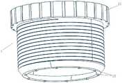
附图1是本实用新型一种暴露手术入路深处的扩张装置示意图。FIG. 1 is a schematic diagram of an expansion device of the present invention for exposing the depth of the surgical approach.
暴露手术入路深处的扩张装置Expose dilation devices deep within the surgical approach
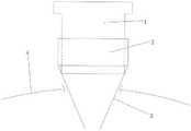
附图2本实用新型一种暴露手术入路深处的扩张装置所述调节机构示意图。FIG. 2 is a schematic diagram of the adjusting mechanism of an expansion device for exposing the depth of the surgical approach according to the present invention.
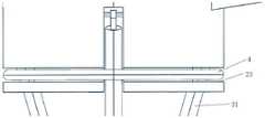
附图3本实用新型另一种暴露手术入路深处的扩张装置示意图。3 is a schematic diagram of another expansion device of the present invention for exposing the depth of the surgical approach.
附图4本实用新型另一种暴露手术入路深处的扩张装置所述限制槽示意图。4 is a schematic diagram of the restriction groove of another expansion device of the present invention for exposing the depth of the surgical approach.
附图5是本实用新型另一种暴露手术入路深处的扩张装置局部放大图。暴露手术入路深处的扩张装置FIG. 5 is a partial enlarged view of another expansion device of the present invention that exposes the depth of the surgical approach. Expose dilation devices deep within the surgical approach
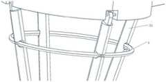
附图6是本实用新型另一种限制装置安装示意图;Accompanying drawing 6 is another kind of restriction device installation schematic diagram of the present invention;
附图7是附图6的局部放大图。暴露手术入路深处的扩张装置FIG. 7 is a partial enlarged view of FIG. 6 . Expose dilation devices deep within the surgical approach
附图8是本实用新型又一种限制装置示意图8 is a schematic diagram of another restriction device of the present invention
附图9本实用新型另一种暴露手术入路深处的扩张装置平面示意图。9 is a schematic plan view of another expansion device of the present invention for exposing the depth of the surgical approach.
附图10本实用新型又一种暴露手术入路深处的扩张装置平面示意图。10 is a schematic plan view of another expansion device of the present invention for exposing the depth of the surgical approach.
附图11本实用新型一种暴露手术入路深处的扩张装置所述操纵杆示意图。Figure 11 is a schematic diagram of the joystick of an expansion device for exposing the depth of a surgical approach according to the present invention.
附图12本实用新型一种手术扩张装置暴露手术入路深处的扩张装置其支撑架平面示意图Figure 12 is a schematic plan view of the support frame of a surgical expansion device of the present invention for exposing the depth of the surgical approach
具体实施方式Detailed ways
下面结合具体实施方式,进一步阐述本实用新型专利。应理解,这些实施例仅用于说明本实用新型专利而不用于限制本实用新型专利的范围。此外应理解,在阅读了本实用新型专利记载的内容之后,本领域技术人员可以对本实用新型专利作各种改动或修改,这些等价形式同样落于本申请所附权利要求书所限定的范围。Below in conjunction with specific embodiments, the utility model patent is further described. It should be understood that these embodiments are only used to illustrate the patent of the present invention and are not used to limit the scope of the patent of the present invention. In addition, it should be understood that after reading the contents recorded in the patent of the present invention, those skilled in the art can make various changes or modifications to the patent of the present invention, and these equivalent forms also fall within the scope defined by the appended claims of the application. .
附图中涉及的附图标记和组成部分如下所示:The reference numerals and components involved in the drawings are as follows:
1.调节机构 2.固定机构 3.扩张机构1. Adjusting
11.防滑部 12.照明装置 21.手柄11.
22.支撑架 31.第一扩张段 32.第二扩张段22.
33.操纵杆 4.限制机构 34.安装槽33.
23.限制槽23. Limit slot
实施例1Example 1
请参见附图1,附图1是本实用新型一种暴露手术入路深处的扩张装置示意图。一种暴露手术入路深处的扩张装置,包括调节机构1、固定机构2、扩张机构3;所述固定机构2为中空圆环结构,所述扩张机构3为条形结构,其一端端部与所述固定机构2其圆环的端部通过旋转轴铰接;所述固定机构2沿圆周均匀设有4条所述扩张机构3,所述扩张机构3 的数量还可以为3条、5条等,若干所述扩张结构组成爪形结构,所述扩张结构的外壁采用磨砂式设计,可以一定程度防止术中移位;所述扩张机构3包括第一扩张段31、第二扩张段32;所述第一扩张段31与所述第二扩张段32呈一定角度;所述第一扩张段31一端与所述固定机构2相连;若干所述第二扩张段32可聚集贴合于一处,优选的,所述第二扩张段 32为锥形结构,便于手术进入;优选的,所述第二扩张段32其上可设置刻度线(图中未示出)。所述调节机构1同样为中空的圆柱体,其套接于所述固定机构2内。所述调节机构1 其外壁与所述固定机构2其内壁通过螺纹活动连接,所述调节机构1其上还设有防滑部11,可以为包裹于环状柱体外沿的软胶,用于握持旋转。暴露手术入路深处的扩张装置所述调节机构1其一端与所述第一扩张段31相接触,当所述调节机构1相对于所述固定机构2内壁伸缩时,其伸缩长度即可控制所述第一扩张段31相对于固定结构的扩张角度。Please refer to FIG. 1. FIG. 1 is a schematic diagram of an expansion device of the present invention for exposing the depth of a surgical approach. An expansion device for exposing the depth of a surgical approach, comprising an
本实用新型的使用方式:在需要扩张手术入路的手术中,在初始状态下,若干所述第二扩张段32互相贴合,若干所述第一扩张段31构成锥形结构,所述调节机构1其一端与第一扩张段31的内壁相接触。进行入路扩张时,将贴合的所述第二扩张段32深入手术入路既定的距离,旋转所述调节机构1,使其向下移动,对应的,所述第一扩张段31受到所述调节机构1的压力,带动所述第二扩张段32进行扩张,撑开手术入路。因此,通过控制所述调节机构1即可以控制所述扩张机构3的打开角度。How to use the utility model: in the operation that needs to expand the surgical approach, in the initial state, a plurality of the second expansion sections 32 are attached to each other, and a plurality of the
需要说明的是,本实用新型所述暴露手术入路深处的扩张装置尤其适合于肛门部外括约肌裸化游离术,其可以顺利扩张括约肌间入路,打开内外括约肌间隙。本实施例中所述扩张机构3包括第一扩张段31、第二扩张段32;所述第一扩张段31与所述第二扩张段32呈一定角度;所述第二扩张段32之间可聚合相贴,可自由深入小切口手术入路,且其在扩张时,所述第二扩张段32远端扩张范围大,近端扩张范围小,既扩大了手术入路深处的手术空间,又避免了入路切口的扩大;应理解的是第一扩张段31、第二扩张段32之间可以有弧形过渡,所述扩张机构3还可以包括第三扩张段等。It should be noted that the expansion device for exposing the depth of the surgical approach described in the present invention is especially suitable for the bare external sphincter of the anus, which can smoothly expand the intersphincteric approach and open the internal and external sphincter space. In this embodiment, the
请参见附图2,附图2本实用新型一种暴露手术入路深处的扩张装置所述调节机构示意图。在一些优选的实施例中,所述调节机构1其端部设有照明装置12,如LED灯等,对应的,所述调节机构1内还可设置为照明装置12提供电源的电源元件,照明装置12其可直接照射手术入路,提供清晰的手术视野;优选的,所述固定机构2其上还可设置手柄21,方便握持控制。暴露手术入路深处的扩张装置Please refer to FIG. 2 , which is a schematic diagram of the adjusting mechanism of an expansion device for exposing the depth of the surgical approach of the present invention. In some preferred embodiments, the end of the
实施例2Example 2
请参见附图3、附图4,附图3本实用新型另一种暴露手术入路深处的扩张装置示意图;附图4本实用新型另一种暴露手术入路深处的扩张装置所述限制槽示意图。本实施例与实施例1基本相同,其不同之处在于,本实施例中,所述暴露手术入路深处的扩张装置包括限制机构4,应理解的是,当所述扩张机构3在所述调节机构1的支撑下,向外扩张,但其收合依赖于外界的施力使其聚拢,因此为解决聚拢的问题,在所述扩张机构3的外围设置限制机构4,本实施例中,所述限制机构4为弹性圈,所述弹性圈套接于所述扩张机构3外围,给所述扩张机构3施加一向内聚拢的力,当所述调节机构1撑开所述扩张机构3时,由于所述弹性圈具有弹性,因此其不影响所述扩张机构3的扩张,即不影响手术入路的形成。Please refer to Figure 3 and Figure 4, Figure 3 is a schematic diagram of another expansion device of the present invention for exposing the depth of the surgical approach; Figure 4 shows another expansion device of the present invention that exposes the depth of the surgical approach Schematic diagram of the confinement slot. This embodiment is basically the same as
请再次参看附图3、附图4、附图5;附图5是本实用新型另一种暴露手术入路深处的扩张装置局部放大图。需要说明的是,在本实施例中,所述固定机构2其上设有限制槽23,所述限制槽23位于所述固定机构2与所述扩张机构3的铰接处下方,用于为所述限制机构 4即弹性圈提供限位轨道,当所述扩张机构3扩张时,所述扩张机构3带动所述弹性圈在所述限位槽23内滑动,应理解的是,在本实施例中,由于所述固定机构2其内壁设有限制槽 23,因此所述固定机构2的壁厚相对较厚(图中未示出)。Please refer to Figure 3, Figure 4, and Figure 5 again; Figure 5 is a partial enlarged view of another expansion device of the present invention that exposes the depth of the surgical approach. It should be noted that, in this embodiment, the
请参见附图6、附图7;附图6是本实用新型另一种限制装置安装示意图;附图7是附图6的局部放大图。优选的,在一些实施例中,所述限制机构4即弹性圈还可以集成于所述扩张机构3内,即所述扩张机构3其上设有安装槽34,所述弹性圈设于所述安装槽34内,同样,所述安装槽34可以限制所述弹性圈的位置。Please refer to Figure 6 and Figure 7; Figure 6 is a schematic diagram of the installation of another restriction device of the present invention; Figure 7 is a partial enlarged view of Figure 6. Preferably, in some embodiments, the restricting
附图8是本实用新型又一种限制装置示意图;优选的,在一些实施例中,所述限制机构4还可以为弹性卡,即通过弹簧与所述固定机构2侧壁相连,分别控制对应的扩张机构3。8 is a schematic diagram of another restriction device of the present invention; preferably, in some embodiments, the
实施例3Example 3
请参见附图9,附图9本实用新型另一种暴露手术入路深处的扩张装置平面示意图,其中,图中标号4表示为皮肤,其上的缺口则为肛门;本实施例与实施例1基本相同,其不同之处在于,本实施例的扩张机构3、固定机构2构造不同,适用于不同的手术环境;本实施例中,所述扩张机构3为直线形,其端部端点相合,适合与肛门处的可扩张,其在伸入肛门的同时即可打开入路,再调节所述调节机构1,即可进一步打开所述扩张机构3扩张肛肠,其优点在于,无需辅助,即可直接深入肛肠深处,且所述扩张机构3能够沿周边均匀扩张,又不会过多的遮挡肠壁视野。Please refer to FIG. 9 , which is a schematic plan view of another expansion device of the present invention for exposing the depth of the surgical approach, wherein the
请参见附图10,附图10本实用新型又一种暴露手术入路深处的扩张装置平面示意图。在一些优选的实施例中,所述固定机构2可以为方形环状中空结构,在其长边上对称设有若干扩张机构3,所述调节机构1与方形环状的固定机构2相适配,其不同之处在于,所述调节机构1与所述固定机构2卡接固定。方形环状固定机构2利于横向切口的打开,相对于现有的牵拉式的切口入路打开,其无需提供人力或额外的固定件固定牵拉件以维持入路的打开。Please refer to FIG. 10 , which is a schematic plan view of another expansion device of the present invention for exposing the depth of the surgical approach. In some preferred embodiments, the
实施例4Example 4
请参见附图11,附图11本实用新型一种暴露手术入路深处的扩张装置所述操纵杆示意图。本实施例与实施例1基本相同,其不同之处在于,所述扩张机构3与所述固定机构2的铰接的另一端设有操纵杆33,所述操纵杆33为所述扩张机构3与所述固定机构2铰接点的延伸段,拨动所述操纵杆33,即可以控制与其相对应的扩张机构3的角度变化;所述操纵杆33可以位于扩张机构3的延长线上,亦可以与其呈一定角度。本实施例在应用时,可以根据手术过程的需要,临时通过所述操纵杆33扩张对应的扩张机构3,临时增大某一方位的视野,方便手术的进行。Please refer to FIG. 11 , which is a schematic diagram of the joystick of an expansion device of the present invention for exposing the depth of a surgical approach. This embodiment is basically the same as the first embodiment, the difference lies in that the other end of the hinged connection between the
实施例5Example 5
请参见附图12,附图12本实用新型一种手术扩张装置暴露手术入路深处的扩张装置其支撑架平面示意图;其中图中标号4表示为皮肤,其上的缺口则为手术切口。进一步,所述固定机构2其上还设有支撑架22,所述支撑架22可以有若干组,均匀分布设置在固定机构2外壁,优选的,所述支撑架22与固定机构2侧壁的连接处可设置为带有阻尼的活动连接,活动连接可以方便调整支撑位置,阻尼可以保证支撑的稳定;其支撑架22可将所述固定机构2稳定的支撑于所述手术入路上方,提供稳定的手术环境,尤其适合在手术入路较浅的时候提供辅助支撑,使所述扩张机构3的长度较长时,依然能提供稳定的手术环境,同时施术者不仅可以利用固定机构2及调节机构1的中空部位施术,还可通过支撑架22及扩张机构3之间的间隙侧向施术。Please refer to Figure 12. Figure 12 is a schematic plan view of the support frame of a surgical expansion device of the present invention for exposing the depth of the surgical approach; the
需要说明的是,本实用新型相关实施例中所述手柄21由施术者握持控制,亦能维持施术环境的稳定。It should be noted that, in the relevant embodiments of the present invention, the
以上所述仅是本实用新型专利的优选实施方式,应当指出,对于本技术领域的普通技术人员,在不脱离本实用新型专利原理的前提下,还可以做出若干改进和补充,这些改进和补充也应视为本实用新型专利的保护范围。The above is only the preferred embodiment of the present invention patent. It should be pointed out that for those skilled in the art, without departing from the principle of the present invention patent, several improvements and supplements can be made. These improvements and Supplements should also be regarded as the scope of protection of the utility model patent.
Claims (10)
Translated fromChinesePriority Applications (1)
| Application Number | Priority Date | Filing Date | Title |
|---|---|---|---|
| CN202220129639.XUCN217244555U (en) | 2022-01-18 | 2022-01-18 | A dilation device that exposes the depths of the surgical approach |
Applications Claiming Priority (1)
| Application Number | Priority Date | Filing Date | Title |
|---|---|---|---|
| CN202220129639.XUCN217244555U (en) | 2022-01-18 | 2022-01-18 | A dilation device that exposes the depths of the surgical approach |
Publications (1)
| Publication Number | Publication Date |
|---|---|
| CN217244555Utrue CN217244555U (en) | 2022-08-23 |
Family
ID=82897280
Family Applications (1)
| Application Number | Title | Priority Date | Filing Date |
|---|---|---|---|
| CN202220129639.XUExpired - Fee RelatedCN217244555U (en) | 2022-01-18 | 2022-01-18 | A dilation device that exposes the depths of the surgical approach |
Country Status (1)
| Country | Link |
|---|---|
| CN (1) | CN217244555U (en) |
Cited By (1)
| Publication number | Priority date | Publication date | Assignee | Title |
|---|---|---|---|---|
| CN114191011A (en)* | 2022-01-18 | 2022-03-18 | 上海中医药大学附属曙光医院 | Expansion device for exposing deep part of operation approach |
- 2022
- 2022-01-18CNCN202220129639.XUpatent/CN217244555U/ennot_activeExpired - Fee Related
Cited By (1)
| Publication number | Priority date | Publication date | Assignee | Title |
|---|---|---|---|---|
| CN114191011A (en)* | 2022-01-18 | 2022-03-18 | 上海中医药大学附属曙光医院 | Expansion device for exposing deep part of operation approach |
Similar Documents
| Publication | Publication Date | Title |
|---|---|---|
| WO2015007233A1 (en) | Ureterorenoscope with bendable head end | |
| US20130103072A1 (en) | Anoscope | |
| BRPI0618138B1 (en) | Extendable wide-angle surgical lighting system and wide-angle extendable illuminator | |
| CN217244555U (en) | A dilation device that exposes the depths of the surgical approach | |
| WO2007139993A2 (en) | Illuminated surgical access system including a surgical access device and integrated light emitter | |
| WO2020199307A1 (en) | Hollow, vectorial, and supportive multi-functional protection device for minimally invasive surgery | |
| JP2015532884A (en) | Adjustable loop fiber optic illuminator for surgery | |
| CN108421149A (en) | A kind of stool drainage anal canal | |
| CN110251062A (en) | A video-assisted endoscopy kit for anal fistula treatment | |
| US10485700B1 (en) | Ophthalmic surgical instruments and snares thereof | |
| CN116077001A (en) | A laryngoscopy system | |
| CN209048100U (en) | A kind of cystoscope convenient for operation | |
| CN212547024U (en) | A kind of auxiliary device for endoscopic surgery through natural orifice | |
| CN221655576U (en) | Adjustable vaginal dilator | |
| CN108553131A (en) | A kind of nerve endoscope operations on cranium and brain lane device | |
| CN114191011A (en) | Expansion device for exposing deep part of operation approach | |
| CN118402754A (en) | Vaginal speculum opening device for reproduction examination | |
| CN209437219U (en) | A kind of Novel laparoscope | |
| CN202173384U (en) | Multifunctional adjustable support laryngoscope | |
| CN114909622A (en) | Nursing lamp for operating room based on lamp bead position adjustment mechanism | |
| WO1989002719A1 (en) | Improved laryngoscope | |
| CN113712683A (en) | Uterine cavity expander | |
| CN219940571U (en) | Adjustable anoscope | |
| CN209826660U (en) | A light-guiding anorectal distractor | |
| CN217090798U (en) | An eyelid expander for ophthalmology clinical use |
Legal Events
| Date | Code | Title | Description |
|---|---|---|---|
| GR01 | Patent grant | ||
| GR01 | Patent grant | ||
| CF01 | Termination of patent right due to non-payment of annual fee | Granted publication date:20220823 | |
| CF01 | Termination of patent right due to non-payment of annual fee |