CN217201921U - Automatic forklift - Google Patents
Automatic forkliftDownload PDFInfo
- Publication number
- CN217201921U CN217201921UCN202220215173.5UCN202220215173UCN217201921UCN 217201921 UCN217201921 UCN 217201921UCN 202220215173 UCN202220215173 UCN 202220215173UCN 217201921 UCN217201921 UCN 217201921U
- Authority
- CN
- China
- Prior art keywords
- forklift
- assembly
- automatic
- lifting
- radar
- Prior art date
- Legal status (The legal status is an assumption and is not a legal conclusion. Google has not performed a legal analysis and makes no representation as to the accuracy of the status listed.)
- Active
Links
Images


Classifications
- Y—GENERAL TAGGING OF NEW TECHNOLOGICAL DEVELOPMENTS; GENERAL TAGGING OF CROSS-SECTIONAL TECHNOLOGIES SPANNING OVER SEVERAL SECTIONS OF THE IPC; TECHNICAL SUBJECTS COVERED BY FORMER USPC CROSS-REFERENCE ART COLLECTIONS [XRACs] AND DIGESTS
- Y02—TECHNOLOGIES OR APPLICATIONS FOR MITIGATION OR ADAPTATION AGAINST CLIMATE CHANGE
- Y02T—CLIMATE CHANGE MITIGATION TECHNOLOGIES RELATED TO TRANSPORTATION
- Y02T90/00—Enabling technologies or technologies with a potential or indirect contribution to GHG emissions mitigation
- Y02T90/10—Technologies relating to charging of electric vehicles
- Y02T90/14—Plug-in electric vehicles
Landscapes
- Forklifts And Lifting Vehicles (AREA)
Abstract
Translated fromChinese
Description
Translated fromChinese技术领域technical field
本申请涉及叉车技术领域,具体而言,涉及一种自动叉车。The present application relates to the technical field of forklift trucks, and in particular, to an automatic forklift truck.
背景技术Background technique
叉车是工业搬运车辆,是指对成件托盘货物进行装卸、堆垛和短距离运输作业的各种轮式搬运车辆,常用于仓储大型物件的运输。Forklift is an industrial handling vehicle, which refers to various wheeled handling vehicles for loading and unloading, stacking and short-distance transportation of palletized goods. It is often used for the transportation of large-scale objects in storage.
目前使用的叉车,大部分仍是由人工操作或使用磁轨导航以及RFID定位技术来进行自主移动运送货物,该方法虽然能够满足一定的需要,但是局限性较大,需要针对仓库进行较大的改造,不具有通用性。Most of the currently used forklifts are still manually operated or use magnetic track navigation and RFID positioning technology to move goods autonomously. Although this method can meet certain needs, it has great limitations and needs to be carried out for warehouses. Retrofit, not universal.
实用新型内容Utility model content
本申请提供自动叉车,以解决上述人工成本高、叉车通用性差的问题。The present application provides an automatic forklift to solve the above-mentioned problems of high labor cost and poor forklift versatility.
本申请的实施例是这样实现的:The embodiments of the present application are implemented as follows:
一种自动叉车,包括叉车本体、升降组件和承载组件,所述升降组件设置于所述叉车本体的一侧,所述承载组件传动连接所述升降组件,还包括:An automatic forklift includes a forklift body, a lifting assembly and a bearing assembly, the lifting assembly is arranged on one side of the forklift body, the bearing assembly is drivingly connected to the lifting assembly, and further comprises:
自动导航组件,包括第一雷达和第二雷达,所述第一雷达设置于所述升降组件的顶部,所述第二雷达设置于所述叉车本体的底部;an automatic navigation assembly, including a first radar and a second radar, the first radar is arranged on the top of the lifting assembly, and the second radar is arranged at the bottom of the forklift body;
控制组件,设置于所述叉车本体内,所述控制组件电连接所述自动导航组件,用于根据所述自动导航组件的检测结果调整所述叉车本体的运动状态;a control assembly, disposed in the forklift body, the control assembly is electrically connected to the automatic navigation assembly, and used for adjusting the motion state of the forklift body according to the detection result of the automatic navigation assembly;
3D相机,安装于所述升降组件上,所述3D相机用于识别和锁定目标货物;所述控制组件还用于根据所述3D相机的检测结构控制所述升降组件和承载组件的运动状态。A 3D camera is installed on the lifting assembly, and the 3D camera is used for identifying and locking the target goods; the control assembly is also used for controlling the movement states of the lifting assembly and the carrying assembly according to the detection structure of the 3D camera.
如此,通过设置自动导航组件和3D相机,使叉车能够自动识别周围环境和锁定目标货物,叉车可以在控制组件的作用下,实现自动行驶和自动插取货物,实现仓库物流的无人化操作,提升叉车的通用性,减少人工成本和仓库改造成本。In this way, by setting up the automatic navigation component and 3D camera, the forklift can automatically identify the surrounding environment and lock the target goods. Under the action of the control component, the forklift can realize automatic driving and automatic insertion of goods, and realize the unmanned operation of warehouse logistics. Improve the versatility of forklifts and reduce labor costs and warehouse renovation costs.
在一种可能的实施方式中:In one possible implementation:
所述升降组件包括升降驱动器和升降支架,所述升降驱动器部分设于所述叉车本体内,所述升降支架设置于所述叉车本体的一侧,所述承载组件传动连接所述升降驱动器;The lifting assembly includes a lifting driver and a lifting bracket, the lifting driver is partially arranged in the forklift body, the lifting bracket is arranged on one side of the forklift body, and the bearing assembly is drivingly connected to the lifting driver;
所述第一雷达设置于所述升降支架的顶部;the first radar is arranged on the top of the lifting bracket;
所述3D相机位于所述第一雷达与所述叉车本体之间。The 3D camera is located between the first radar and the forklift body.
在一种可能的实施方式中:In one possible implementation:
所述升降支架上设有安装架,所述3D相机可转动地连接于所述安装架。A mounting bracket is provided on the lifting bracket, and the 3D camera is rotatably connected to the mounting bracket.
在一种可能的实施方式中:In one possible implementation:
两组所述第二雷达对称设置于所述叉车本体的相对两侧。The two sets of second radars are symmetrically arranged on opposite sides of the forklift body.
在一种可能的实施方式中:In one possible implementation:
还包括舵轮组件,设置于所述叉车本体的底部,所述控制组件电连接所述舵轮组件。It also includes a steering wheel assembly, which is arranged on the bottom of the forklift body, and the control assembly is electrically connected to the steering wheel assembly.
在一种可能的实施方式中:In one possible implementation:
还包括滑轮组件,所述滑轮组件设置于所述承载组件的底部。It also includes a pulley assembly, the pulley assembly is arranged on the bottom of the bearing assembly.
在一种可能的实施方式中:In one possible implementation:
所述叉车本体背离所述承载组件的一侧还设有充电电极,用于插接外部电源;A charging electrode is also provided on the side of the forklift body away from the bearing assembly for plugging in an external power supply;
所述充电电极位于两组所述第二雷达之间,且设置于叉车本体的外表面。The charging electrode is located between the two sets of second radars and is arranged on the outer surface of the forklift body.
在一种可能的实施方式中:In one possible implementation:
所述升降支架的顶部还设有示廓灯,所述示廓灯设置于所述第一雷达的下方。The top of the lifting bracket is also provided with a position indicator light, and the position indicator light is arranged below the first radar.
在一种可能的实施方式中:In one possible implementation:
所述自动叉车还包括接口组件;The automatic forklift also includes an interface assembly;
所述接口组件设置于所述叉车本体的一侧表面,所述控制组件电连接所述接口组件。The interface assembly is disposed on one side surface of the forklift body, and the control assembly is electrically connected to the interface assembly.
在一种可能的实施方式中:In one possible implementation:
所述自动叉车还包括配重件;The automatic forklift also includes a counterweight;
所述配重件部分设于所述叉车本体内,用于调整所述自动叉车的重心。The counterweight is partially arranged in the forklift body, and is used to adjust the center of gravity of the automatic forklift.
附图说明Description of drawings
为了更清楚地说明本申请实施例的技术方案,下面将对实施例中的附图作简单地介绍,应当理解,以下附图仅示出了本申请的某些实施例,因此不应被看作是对范围的限定,对于本领域普通技术人员来讲,在不付出创造性劳动的前提下,还可以根据这些附图获得其他相关的附图。In order to illustrate the technical solutions of the embodiments of the present application more clearly, the accompanying drawings in the embodiments will be briefly introduced below. It should be understood that the following drawings only show some embodiments of the present application, and therefore should not be viewed as As a limitation of the scope, for those of ordinary skill in the art, other related drawings can also be obtained according to these drawings without any creative effort.
图1为本申请一实施例的自动叉车的结构示意图。FIG. 1 is a schematic structural diagram of an automatic forklift according to an embodiment of the application.
图2为图1所示自动叉车在另一方向上的结构示意图。FIG. 2 is a schematic structural diagram of the automatic forklift shown in FIG. 1 in another direction.
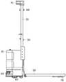
图3为图1所示自动叉车的正视图。FIG. 3 is a front view of the automatic forklift shown in FIG. 1 .
图4为图1所示自动叉车的侧视图。FIG. 4 is a side view of the automatic forklift shown in FIG. 1 .
主要元件符号说明:Description of main component symbols:


具体实施方式Detailed ways
下面将结合本申请实施例中的附图,对本申请实施例中的技术方案进行清楚、完整地描述,显然,所描述的实施例仅是本申请一部分实施例,而不是全部的实施例。The technical solutions in the embodiments of the present application will be clearly and completely described below with reference to the accompanying drawings in the embodiments of the present application. Obviously, the described embodiments are only a part of the embodiments of the present application, but not all of the embodiments.
需要说明的是,当元件被称为“固定于”另一个元件,它可以直接在另一个元件上或者也可以存在居中的元件。当一个元件被认为是“连接”另一个元件,它可以是直接连接到另一个元件或者可能同时存在居中元件。当一个元件被认为是“设置于”另一个元件,它可以是直接设置在另一个元件上或者可能同时存在居中元件。本文所使用的术语“垂直的”、“水平的”、“左”、“右”以及类似的表述只是为了说明的目的。It should be noted that when an element is referred to as being "fixed to" another element, it can be directly on the other element or intervening elements may also be present. When an element is referred to as being "connected" to another element, it can be directly connected to the other element or intervening elements may also be present. When an element is referred to as being "disposed on" another element, it can be directly disposed on the other element or intervening elements may also be present. The terms "vertical," "horizontal," "left," "right," and similar expressions are used herein for illustrative purposes only.
除非另有定义,本文所使用的所有的技术和科学术语与属于本申请领域的技术人员通常理解的含义相同。本文中在本申请的说明书中所使用的术语只是为了描述具体的实施方式的目的,不是旨在于限制本申请。本文所使用的术语“或/及”包括一个或多个相关的所列项目的任意的和所有的组合。Unless otherwise defined, all technical and scientific terms used herein have the same meaning as commonly understood by one of ordinary skill in the art of this application. The terms used herein in the specification of the present application are for the purpose of describing particular embodiments only, and are not intended to limit the present application. As used herein, the term "or/and" includes any and all combinations of one or more of the associated listed items.
本申请的一些实施方式作详细说明。在不冲突的情况下,下述的实施方式及实施方式中的特征可以相互组合。Some embodiments of the present application are described in detail. The following embodiments and features of the embodiments may be combined with each other without conflict.
参见图1和图2,本实施例提供一种自动叉车100,包括叉车本体10、升降组件20、承载组件30、自动导航组件40、控制组件和3D相机50。所述升降组件20设置于所述叉车本体10的一侧,所述承载组件30传动连接所述升降组件20,叉车本体10可以带动升降组件20和承载组件30移动至预定位置。自动导航组件40包括第一雷达41和第二雷达42,所述第一雷达41设置于所述升降组件20的顶部,所述第二雷达42设置于所述叉车本体10的底部。所述控制组件设置于所述叉车本体10内,所述控制组件电连接所述自动导航组件40,用于根据所述自动导航组件40的检测结果调整所述叉车本体10的运动状态。所述3D相机50安装于所述升降组件20上,所述3D相机50用于识别和锁定目标货物,所述控制组件还用于根据所述3D相机50的检测结构控制所述升降组件20和承载组件30的运动状态。Referring to FIGS. 1 and 2 , the present embodiment provides an
进一步地,所述升降组件20包括升降驱动器22和升降支架21,所述升降驱动器22部分设于所述叉车本体10内,所述升降支架21设置于所述叉车本体10的一侧,所述承载组件30传动连接所述升降驱动器22,并可移动地设置于所述升降支架21背离所述叉车本体10的一侧。所述升降驱动器22用于驱动所述承载组件30沿所述升降支架21移动或停止。Further, the
请继续参阅图3,在本申请的实施例中,所述第一雷达41设置于所述升降支架21的顶部,用于识别行驶路线,以导航叉车本体10的移动方向。两组所述第二雷达42对称设置于所述叉车本体10的相对两侧,用于检测叉车周围的障碍物,辅助叉车在行驶过程中避开障碍物,提升叉车移动的稳定性和安全性。Please continue to refer to FIG. 3 , in the embodiment of the present application, the
进一步地,所述3D相机50位于所述第一雷达41与所述叉车本体10之间,以便锁定目标货物,减少3D相机50被遮挡的风险。3D相机50设置的位置太高会影响识别位置较低的货物,3D相机50设置的位置较矮则容易导致3D相机50被遮挡,无法识别目标货物。具体地,所述升降支架21上设有安装架23,所述安装架23大致位于升降支架21的中部,所述3D相机50可转动地连接于所述安装架23,以便识别不同位置的目标货物,控制组件根据3D相机50的识别结果,控制叉车本体10和/或升降驱动器22启动或停止,从而带动承载机构移动,以自动插取和搬运货物。Further, the
请再次参阅图2,所述自动叉车100还包括舵轮组件60,所述舵轮组件60设置于所述叉车本体10的底部,所述控制组件电连接所述舵轮组件60,以便根据自动导航组件40和/或3D相机50的检测信号控制舵轮的转动方向,从而调整叉车本体10的移动方向。Please refer to FIG. 2 again, the
进一步地,所述自动叉车100还还包括滑轮组件70,所述滑轮组件70设置于所述承载组件30的底部。滑轮组件70为从动件,随叉车本体10的移动而转动,用于辅助自动叉车100移动,减少承载组件30与地面之间的摩擦力。Further, the
请参阅图3和图4,所述叉车本体10背离所述承载组件30的一侧还设有充电电极11,用于插接外部电源,以对叉车本体10内的电池进行充电。所述充电电极11位于两组所述第二雷达42之间,且设置于叉车本体10的外表面,使得自动叉车100可以运行至充电站并自行对位充电电极11与充电位点,实现自动充电。Referring to FIGS. 3 and 4 , the side of the
进一步地,所述自动叉车100还包括接口组件12和配重件13。所述接口组件12设置于所述叉车本体10的一侧表面,所述控制组件电连接所述接口组件12。外部设备可以通过接口组件12连接所述控制组件,以便调整控制组件的内部程序,实现对自动叉车100的优化、检修和维护。所述配重件13部分设于所述叉车本体10内,用于调整所述自动叉车100的重心,减少自动叉车100在移动货物时发生倾倒、侧翻等问题。Further, the
在本申请的实施例中,所述升降支架21的顶部还设有示廓灯80,用于警示自动叉车100的高度范围,提高自动叉车100的安全性能。优选地,所述示廓灯80设置于所述第一雷达41的下方,以避免遮挡所述第一雷达41,影响第一雷达41的检测准确性。In the embodiment of the present application, the top of the lifting
本申请的自动叉车100通过设置自动导航组件40和3D相机50,使叉车能够自动识别周围环境和锁定目标货物,在控制组件的作用下,实现自动行驶和自动插取货物,实现仓库物流的无人化操作,提升叉车的通用性,减少人工成本和仓库改造成本。The
以上实施方式仅用以说明本申请的技术方案而非限制,尽管参照以上较佳实施方式对本申请进行了详细说明,本领域的普通技术人员应当理解,可以对本申请的技术方案进行修改或等同替换都不应脱离本申请技术方案的精神和范围。The above embodiments are only used to illustrate the technical solutions of the present application rather than limitations. Although the present application has been described in detail with reference to the above preferred embodiments, those of ordinary skill in the art should understand that the technical solutions of the present application can be modified or equivalently replaced. Neither should depart from the spirit and scope of the technical solutions of the present application.
Claims (10)
Priority Applications (1)
| Application Number | Priority Date | Filing Date | Title |
|---|---|---|---|
| CN202220215173.5UCN217201921U (en) | 2022-01-26 | 2022-01-26 | Automatic forklift |
Applications Claiming Priority (1)
| Application Number | Priority Date | Filing Date | Title |
|---|---|---|---|
| CN202220215173.5UCN217201921U (en) | 2022-01-26 | 2022-01-26 | Automatic forklift |
Publications (1)
| Publication Number | Publication Date |
|---|---|
| CN217201921Utrue CN217201921U (en) | 2022-08-16 |
Family
ID=82793404
Family Applications (1)
| Application Number | Title | Priority Date | Filing Date |
|---|---|---|---|
| CN202220215173.5UActiveCN217201921U (en) | 2022-01-26 | 2022-01-26 | Automatic forklift |
Country Status (1)
| Country | Link |
|---|---|
| CN (1) | CN217201921U (en) |
Cited By (1)
| Publication number | Priority date | Publication date | Assignee | Title |
|---|---|---|---|---|
| EP4335808A1 (en)* | 2022-09-09 | 2024-03-13 | Kabushiki Kaisha Toyota Jidoshokki | Sensor and indicator light mounting structure, and cargo handling vehicle |
- 2022
- 2022-01-26CNCN202220215173.5Upatent/CN217201921U/enactiveActive
Cited By (1)
| Publication number | Priority date | Publication date | Assignee | Title |
|---|---|---|---|---|
| EP4335808A1 (en)* | 2022-09-09 | 2024-03-13 | Kabushiki Kaisha Toyota Jidoshokki | Sensor and indicator light mounting structure, and cargo handling vehicle |
Similar Documents
| Publication | Publication Date | Title |
|---|---|---|
| CN111320107B (en) | Automatic loading, unloading and transporting integrated carrying device, system and method | |
| EP3842605B1 (en) | Intelligent parking lot and cluster transport robot thereof | |
| TWI753563B (en) | Forklift-type automated guided vehicle | |
| CN105712249B (en) | Intelligent carrier system using screw rod for jacking | |
| CN106927395A (en) | Automatic guided vehicle and unmanned handling system | |
| CN114314426B (en) | Unmanned pallet truck and working method thereof | |
| WO2023103674A1 (en) | Agv forklift | |
| CN113443585A (en) | Stacking robot | |
| CN206720664U (en) | Automatic guided vehicle and unmanned handling system | |
| CN110104094A (en) | It is a kind of tracked based on colour band vision, the heavily loaded AGV of differential 4 wheel driven | |
| CN217201921U (en) | Automatic forklift | |
| CN115367019A (en) | An AGV intelligent guided vehicle with active obstacle avoidance | |
| CN115626587A (en) | Laser navigation AGV forklift and control method thereof | |
| CN108557708A (en) | Fork-lift type AGV trolleies | |
| CN219949345U (en) | Lifting robot, combined robot and warehousing system | |
| CN220520069U (en) | Omnidirectional walking device suitable for industrial vehicle and industrial vehicle | |
| CN211198487U (en) | Omnidirectional movement forklift | |
| CN109677819A (en) | Automated guided vehicle and cargo movement system | |
| CN216662390U (en) | But heavy load AGV of outdoor operation | |
| CN219174134U (en) | Laser navigation AGV fork truck | |
| EP4175847B1 (en) | Materials handling vehicle charging system comprising a floor-mounted charging plate | |
| CN212022350U (en) | An AGV car body structure | |
| CN114105041A (en) | But heavy load AGV of outdoor operation | |
| CN210338113U (en) | Heavy load AGV based on typewriter ribbon vision is sought mark, differential four drives | |
| CN214059766U (en) | An unmanned forklift |
Legal Events
| Date | Code | Title | Description |
|---|---|---|---|
| GR01 | Patent grant | ||
| GR01 | Patent grant |