CN217087772U - Battery charging circuit and DC-DC converter having the same - Google Patents
Battery charging circuit and DC-DC converter having the sameDownload PDFInfo
- Publication number
- CN217087772U CN217087772UCN202123454012.6UCN202123454012UCN217087772UCN 217087772 UCN217087772 UCN 217087772UCN 202123454012 UCN202123454012 UCN 202123454012UCN 217087772 UCN217087772 UCN 217087772U
- Authority
- CN
- China
- Prior art keywords
- switch module
- battery
- electrically connected
- voltage
- current source
- Prior art date
- Legal status (The legal status is an assumption and is not a legal conclusion. Google has not performed a legal analysis and makes no representation as to the accuracy of the status listed.)
- Active
Links
Images


Landscapes
- Charge And Discharge Circuits For Batteries Or The Like (AREA)
Abstract
Translated fromChinese
Description
Translated fromChinese技术领域technical field
本实用新型涉及电池充电技术领域,尤其是涉及一种电池充电电路及具有其的DC-DC变换器。The utility model relates to the technical field of battery charging, in particular to a battery charging circuit and a DC-DC converter having the same.
背景技术Background technique
如图1所示为锂电池的恒流恒压充电过程,充电过程中,先以恒定电流进行恒流充电,当充电电压达到预定值时,则转为恒压充电;在恒压充电过程中,充电电流会逐渐减小,当充电电流下降到预定值时,电池完全充满。在锂电池的充电过程中,为了实现恒流和恒压充电,一般都是对充放电的电流进行调节控制,通过调节充电电流来保持恒流和恒压。Figure 1 shows the constant current and constant voltage charging process of the lithium battery. During the charging process, the constant current charging is performed with a constant current first, and when the charging voltage reaches a predetermined value, it is switched to constant voltage charging; during the constant voltage charging process , the charging current will gradually decrease, and when the charging current drops to a predetermined value, the battery is fully charged. In the charging process of lithium batteries, in order to achieve constant current and constant voltage charging, the current of charging and discharging is generally adjusted and controlled, and the constant current and constant voltage are maintained by adjusting the charging current.
在现有技术中,为电池充电的DC-DC变换器一般采用的都是boost、buck、boost-buck等拓扑电路,如图2所示为常见的一种boost拓扑电路。这些拓扑电路,一般都是采用电压源来提供充电电流;然而,在电池的充电过程中,无论是恒流充电还是恒压充电阶段,本质都是通过调节充电电流来实现恒流和恒压的,而采用电压源作为输入,对充电电流的控制不够直接,调节速度不够快。In the prior art, a DC-DC converter for charging a battery generally adopts topology circuits such as boost, buck, and boost-buck, and a common boost topology circuit is shown in FIG. 2 . These topological circuits generally use a voltage source to provide the charging current; however, during the charging process of the battery, whether it is a constant current charging or a constant voltage charging stage, the essence is to adjust the charging current to achieve constant current and constant voltage. , and the voltage source is used as the input, the control of the charging current is not direct enough, and the adjustment speed is not fast enough.
此外,现有的拓扑电路,在调节充电电压时需要一定的恢复时间,存在响应速度不够快的问题。如图2所示出的boost拓扑电路,该电路想要输出电压升高时,需要增大开关管S3的导通时间,但是在第一个周期时,由于S3的导通时间增加,S4的导通时间反而减小,输出电压反而减小,需要一定的时间才能恢复到稳态电压。为了避开这种boost拓扑电路的非最小相位特性对系统稳定性的影响,一般的方法是设计系统闭环带宽使其远远小于右半平面零点的转折频率,但这无疑是以牺牲了系统动态响应的快速性为代价的。而在电池充电过程中,由于电池电压一直在变化,所以要保持恒压充电的话,就需要系统具有比较快的响应速度。In addition, the existing topology circuit needs a certain recovery time when adjusting the charging voltage, and there is a problem that the response speed is not fast enough. In the boost topology circuit shown in Figure 2, when the output voltage of the circuit is to increase, the on-time of the switch S3 needs to be increased, but in the first cycle, due to the increase of the on-time of S3, the on-time of S4 On the contrary, the on-time decreases, the output voltage decreases, and it takes a certain time to restore to the steady-state voltage. In order to avoid the influence of the non-minimum phase characteristics of the boost topology circuit on the system stability, the general method is to design the closed-loop bandwidth of the system to make it much smaller than the corner frequency of the zero point of the right half plane, but this undoubtedly sacrifices the system dynamics. at the expense of quickness of response. In the process of battery charging, since the battery voltage is constantly changing, the system needs to have a relatively fast response speed to maintain constant voltage charging.
实用新型内容Utility model content
本实用新型旨在至少解决现有技术中存在的技术问题之一。为此,本实用新型提出了一种电池充电电路,响应速度较快,能够有效实现对电池的恒流恒压充电。The utility model aims to solve at least one of the technical problems existing in the prior art. Therefore, the utility model proposes a battery charging circuit, which has a fast response speed and can effectively realize constant current and constant voltage charging of the battery.
本实用新型还提出了一种具有上述电池充电电路的DC-DC变换器。The utility model also proposes a DC-DC converter with the above-mentioned battery charging circuit.
第一方面,根据本实用新型实施例的电池充电电路,包括受控电流源、第一开关模块、第二开关模块和控制模块;所述第一开关模块的第一端与所述受控电流源的输出端电性连接,所述第一开关模块的第二端与电池的正极端电性连接;所述第二开关模块的第一端分别与所述电池的负极端和所述受控电流源的输入端电性连接,所述第二开关模块的第二端与所述受控电流源的输出端电性连接;所述控制模块用于采集所述第一开关模块的第二端与所述第二开关模块的第一端之间的第一电压,并根据所述第一电压控制所述第一开关模块和所述第二开关模块的导通和断开,从而对所述受控电流源的输出电流进行斩波控制,以实现对所述电池的恒压充电。In the first aspect, a battery charging circuit according to an embodiment of the present invention includes a controlled current source, a first switch module, a second switch module and a control module; the first end of the first switch module is connected to the controlled current The output terminal of the source is electrically connected, the second terminal of the first switch module is electrically connected to the positive terminal of the battery; the first terminal of the second switch module is respectively connected to the negative terminal of the battery and the controlled The input end of the current source is electrically connected, the second end of the second switch module is electrically connected to the output end of the controlled current source; the control module is used for collecting the second end of the first switch module a first voltage between the first end of the second switch module and the first end of the second switch module, and control the on and off of the first switch module and the second switch module according to the first voltage, so as to control the The output current of the controlled current source is chopped and controlled to achieve constant voltage charging of the battery.
根据本实用新型实施例的电池充电电路,至少具有如下有益效果:通过采用受控电流源来提供充电电流,通过控制模块来控制第一开关模块和第二开关模块的导通时间,进而实现对电池的恒流恒压充电;整个电路的响应速度较快,充电电流直接受控、易于调节,充电电流的精度更高,不易出现过充的情况。The battery charging circuit according to the embodiment of the present invention has at least the following beneficial effects: a controlled current source is used to provide the charging current, and the on-time of the first switch module and the second switch module is controlled by the control module, thereby realizing the Constant current and constant voltage charging of the battery; the response speed of the whole circuit is fast, the charging current is directly controlled and easy to adjust, the accuracy of the charging current is higher, and it is not easy to overcharge.
根据本实用新型的一些实施例,所述第一开关模块包括第一开关管,所述第二开关模块包括第二开关管。According to some embodiments of the present invention, the first switch module includes a first switch tube, and the second switch module includes a second switch tube.
根据本实用新型的一些实施例,所述第一开关管和/或所述第二开关管采用MOS管。According to some embodiments of the present invention, the first switch transistor and/or the second switch transistor are MOS transistors.
根据本实用新型的一些实施例,还包括滤波单元,所述滤波单元设置于所述第一开关模块及所述第二开关模块两者与所述电池之间。According to some embodiments of the present invention, a filter unit is further included, and the filter unit is disposed between both the first switch module and the second switch module and the battery.
根据本实用新型的一些实施例,所述滤波单元包括第一电容和第一电感,所述第一电容的一端与所述第一开关模块的第二端电性连接,所述第一电容的另一端分别与所述电池的负极端和所述第二开关模块的第一端电性连接;所述第一电感的一端与所述第一电容的一端电性连接,所述第一电感的另一端与所述电池的正极端电性连接。According to some embodiments of the present invention, the filter unit includes a first capacitor and a first inductor, one end of the first capacitor is electrically connected to the second end of the first switch module, and the first capacitor is electrically connected to the second end of the first switch module. The other end is respectively electrically connected to the negative end of the battery and the first end of the second switch module; one end of the first inductor is electrically connected to one end of the first capacitor, and the first end of the first inductor is electrically connected The other end is electrically connected to the positive terminal of the battery.
根据本实用新型的一些实施例,所述滤波单元采用π型滤波器。According to some embodiments of the present invention, the filtering unit adopts a π-type filter.
根据本实用新型的一些实施例,所述控制模块包括滞环比较器和驱动单元,所述滞环比较器的正向输入端连接所述第一电压,所述滞环比较器的反向输入端连接参考电压;所述驱动单元的输入端与所述滞环比较器的输出端电性连接,所述驱动单元的输出端分别与所述第一开关模块的受控端和所述第二开关模块的受控端电性连接。According to some embodiments of the present invention, the control module includes a hysteresis comparator and a driving unit, a forward input terminal of the hysteresis comparator is connected to the first voltage, and a reverse input terminal of the hysteresis comparator is connected to the first voltage. The terminal is connected to the reference voltage; the input terminal of the driving unit is electrically connected to the output terminal of the hysteresis comparator, and the output terminal of the driving unit is respectively connected to the controlled terminal of the first switch module and the second terminal. The controlled end of the switch module is electrically connected.
根据本实用新型的一些实施例,还包括电流源生成模块,所述电流源生成模块用于生成所述受控电流源。According to some embodiments of the present invention, a current source generating module is further included for generating the controlled current source.
根据本实用新型的一些实施例,所述电流源生成模块采用三电平buck电路或全桥拓扑电路。According to some embodiments of the present invention, the current source generating module adopts a three-level buck circuit or a full-bridge topology circuit.
第二方面,根据本实用新型实施例的DC-DC变换器,包括如本实用新型上述第一方面实施例的电池充电电路。In the second aspect, the DC-DC converter according to the embodiment of the present invention includes the battery charging circuit according to the embodiment of the first aspect of the present invention.
根据本实用新型实施例的DC-DC变换器,至少具有如下有益效果:通过采用上述的电池充电电路,响应速度较快,充电电流直接受控、易于调节,充电电流的精度更高,不易出现过充的情况,能够有效实现对电池的恒流恒压充电。The DC-DC converter according to the embodiment of the present invention has at least the following beneficial effects: by using the above-mentioned battery charging circuit, the response speed is relatively fast, the charging current is directly controlled and easy to adjust, the accuracy of the charging current is higher, and it is not easy to appear In the case of overcharging, it can effectively realize constant current and constant voltage charging of the battery.
本实用新型的附加方面和优点将在下面的描述中部分给出,部分将从下面的描述中变得明显,或通过本实用新型的实践了解到。Additional aspects and advantages of the invention will be set forth, in part, from the following description, and in part will be apparent from the following description, or learned by practice of the invention.
附图说明Description of drawings
本实用新型的上述和/或附加的方面和优点从结合下面附图对实施例的描述中将变得明显和容易理解,其中:The above and/or additional aspects and advantages of the present invention will become apparent and readily understood from the following description of embodiments in conjunction with the accompanying drawings, wherein:
图1为锂电池充电过程的原理示意图;Fig. 1 is the principle schematic diagram of the lithium battery charging process;
图2为现有技术的boost拓扑电路的电路原理图;Fig. 2 is the circuit schematic diagram of the boost topology circuit of the prior art;
图3为本实用新型实施例的电池充电电路的电路原理示意图;3 is a schematic diagram of a circuit principle of a battery charging circuit according to an embodiment of the present invention;
图4为图3示出的电池充电电路在第一开关模块导通时的电路原理示意图;FIG. 4 is a schematic diagram of the circuit principle of the battery charging circuit shown in FIG. 3 when the first switch module is turned on;
图5为图3示出的电池充电电路在第二开关模块导通时的电路原理示意图;5 is a schematic diagram of the circuit principle of the battery charging circuit shown in FIG. 3 when the second switch module is turned on;
图6为本实用新型第一种实施例的电池充电电路的具体电路原理图;6 is a specific circuit schematic diagram of the battery charging circuit according to the first embodiment of the present invention;
图7为本实用新型第二种实施例的电池充电电路的具体电路原理图;7 is a specific circuit schematic diagram of a battery charging circuit according to the second embodiment of the present invention;
图8为图7示出的电池充电电路在恒压充电过程中的工作原理示意图;FIG. 8 is a schematic diagram of the working principle of the battery charging circuit shown in FIG. 7 during constant voltage charging;
图9为图7示出的电池充电电路在恒压充电过程中的充电电压和充电电流的波形变化示意图;9 is a schematic diagram of waveform changes of the charging voltage and charging current of the battery charging circuit shown in FIG. 7 during constant voltage charging;
图10为本实用新型实施例的三电平buck电路的电路原理图;10 is a circuit schematic diagram of a three-level buck circuit according to an embodiment of the present invention;
图11为本实用新型实施例的全桥拓扑电路的电路原理图;11 is a circuit schematic diagram of a full-bridge topology circuit according to an embodiment of the present invention;
附图标记:Reference number:
第一开关模块100、第二开关模块200、开关模块300、滤波单元400。The
具体实施方式Detailed ways
本部分将详细描述本实用新型的具体实施例,本实用新型之较佳实施例在附图中示出,附图的作用在于用图形补充说明书文字部分的描述,使人能够直观地、形象地理解本实用新型的每个技术特征和整体技术方案,但其不能理解为对本实用新型保护范围的限制。This part will describe the specific embodiments of the present invention in detail, and the preferred embodiments of the present invention are shown in the accompanying drawings. Understand each technical feature and overall technical solution of the present invention, but it should not be construed as a limitation on the protection scope of the present invention.
在本实用新型的描述中,若干的含义是一个或者多个,多个的含义是两个以上,大于、小于、超过等理解为不包括本数,以上、以下、以内等理解为包括本数。如果有描述到第一、第二只是用于区分技术特征为目的,而不能理解为指示或暗示相对重要性或者隐含指明所指示的技术特征的数量或者隐含指明所指示的技术特征的先后关系。In the description of the present utility model, the meaning of several is one or more, the meaning of multiple is two or more, greater than, less than, exceeding, etc. are understood as not including this number, above, below, within, etc. are understood as including this number. If it is described that the first and second are only for the purpose of distinguishing technical features, it cannot be understood as indicating or implying relative importance, or indicating the number of indicated technical features or the order of indicated technical features. relation.
本实用新型的描述中,除非另有明确的限定,设置、安装、连接等词语应做广义理解,所属技术领域技术人员可以结合技术方案的具体内容合理确定上述词语在本实用新型中的具体含义。In the description of the present utility model, unless otherwise clearly defined, words such as setting, installation, connection should be understood in a broad sense, and those skilled in the art can reasonably determine the specific meanings of the above-mentioned words in the present utility model in combination with the specific content of the technical solution .
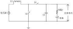
第一方面,参照图3至图7,根据本实用新型实施例的电池充电电路,包括受控电流源、第一开关模块100、第二开关模块200和控制模块300;其中,第一开关模块100的第一端与受控电流源的输出端电性连接,第一开关模块100的第二端与电池的正极端电性连接;第二开关模块200的第一端分别与电池的负极端和受控电流源的输入端电性连接,第二开关模块200的第二端与受控电流源的输出端电性连接;控制模块300用于采集第一开关模块100的第二端与第二开关模块200的第一端之间的第一电压Uo,并根据第一电压Uo控制第一开关模块100及第二开关模块200的导通和断开,从而对受控电流源的输出电流进行斩波控制,以实现对电池的恒压充电。In the first aspect, referring to FIGS. 3 to 7 , a battery charging circuit according to an embodiment of the present invention includes a controlled current source, a
根据本实用新型实施例的电池充电电路,采用受控电流源来提供充电电流;如图3至图5所示,在恒流充电过程中,只需闭合第一开关模块100,并断开第二开关模块200,受控电流源即可为电池提供恒定的充电电流,实现恒流充电;在恒流充电过程中,充电电压持续上升,当充电电压到达预定值时,转为恒压充电;在恒压充电过程中,如图7至图9所示,预先设定上限电压值Ua和下限电压值Ub,控制模块300采集第一电压Uo,当第一电压Uo上升到上限电压值Ua时,控制模块300控制第一开关模块100断开、第二开关模块200导通,此时受控电流源所提供的电流不经过电池,不对电池进行充电,第一电压Uo逐渐下降;当第一电压Uo下降到下限电压值Ub时,控制模块300控制第一开关模块100导通、第二开关模块200断开,受控电流源继续对电池充电,使第一电压Uo逐渐上升至Ua,再切换第一开关模块100和第二开关模块200的状态,使第一电压Uo重新下降至Ub;持续重复上述过程,直至完成对电池的充电。在对电池进行恒压充电的过程中,通过不断切换第一开关模块100和第二开关模块200的导通状态,从而控制充电电流的脉冲,进而控制电池的平均充电电流,最终实现电池的平均充电电压保持不变;即通过对受控电流源的输出电流进行斩波控制,从而实现对电池的恒压充电。如图8和图9所示,在恒压充电过程中,随着充电进程的进行,电池被充入越来越多的电量,电池的电压越来越高,与充电电压的压差就越小,能充入的电流也就越小;第一开关模块100的导通时间逐渐减小,第二开关模块200的导通时间逐渐增加,平均充电电流逐渐减小,电池充电电流也逐渐减小,直至电池充满电;整个阶段一直保持着锂电池的恒压充电。其中,在恒压充电过程中,充电电压会有很微小的波动,但在图9中将充电电压的波形以直线表示。According to the battery charging circuit of the embodiment of the present invention, a controlled current source is used to provide the charging current; as shown in FIG. 3 to FIG. 5 , in the process of constant current charging, only the
由此可见,根据本实用新型实施例的电池充电电路,通过采用受控电流源来提供充电电流,通过控制模块300来控制第一开关模块100和第二开关模块200的导通时间,进而实现对电池的恒流恒压充电;整个电路的响应速度较快,充电电流直接受控、易于调节,充电电流的精度更高,不易出现过充的情况,而且整个电路的结构和控制方法均较为简单可靠。It can be seen that, according to the battery charging circuit of the embodiment of the present invention, the charging current is provided by the controlled current source, and the conduction time of the
需要说明的是,关于上限电压值Ua和下限电压值Ub的具体取值,本领域技术人员可以根据电池的充电电压进行合理选择。假设电池所需的充电电压为5V,则可以设定Ua为5.05V,Ub为4.95V;当然,Ua和Ub也可以是其它较为合理的取值。It should be noted that, with regard to the specific values of the upper limit voltage value Ua and the lower limit voltage value Ub, those skilled in the art can make reasonable selections according to the charging voltage of the battery. Assuming that the charging voltage required by the battery is 5V, Ua can be set to 5.05V and Ub can be set to 4.95V; of course, Ua and Ub can also be other reasonable values.
如图6和图7所示,在本实用新型的一些实施例中,第一开关模块100包括第一开关管S1,第二开关模块200包括第二开关管S2。其中,第一开关管S1和第二开关管S2可以采用MOS管,如Si类MOS管、GaN类MOS管等。可以理解的是,第一开关模块100和第二开关模块200也可以采用其它常见的开关元件,如继电器等,而不限于此。As shown in FIG. 6 and FIG. 7 , in some embodiments of the present invention, the
如图6和图7所示,在本实用新型的一些实施例中,还包括滤波单元400,滤波单元400设置于第一开关模块100和第二开关模块200两者与电池之间。As shown in FIG. 6 and FIG. 7 , in some embodiments of the present invention, a
具体地,如图6所示,滤波单元400包括第一电容C1和第一电感L1,第一电容C1的一端与第一开关模块100的第二端电性连接,第一电容C1的另一端分别与电池的负极端和第二开关模块200的第一端电性连接;第一电感L1的一端与第一电容C1的一端电性连接,第一电感L1的另一端与电池的正极端电性连接。第一电容C1和第一电感L1组成滤波单元400,对充电电流进行滤波,得到平滑的电流信号,再为电池充电。Specifically, as shown in FIG. 6 , the
或者,如图7所示,滤波单元400也可以采用π型滤波器。π型滤波器包括电容C2、电感L2和电容C3,电容C2的一端与第一开关模块100的第二端电性连接,电容C2的另一端分别与电池的负极端和第二开关模块200的第一端电性连接;电感L2的一端与电容C2的一端电性连接,电感L2的另一端分别与电池的正极端和电容C3的一端电性连接,电容C3的另一端分别与电池的负极端和电容C2的另一端电性连接。电容C2、电感L2和电容C3组成滤波单元400,对充电电流进行滤波,得到平滑的电流信号,再为电池充电。Alternatively, as shown in FIG. 7 , the
可以理解的是,滤波单元400也可以采用其他常见的滤波回路,而不限于此。It can be understood that, the
如图7所示,在本实用新型的一些实施例中,控制模块300包括滞环比较器和驱动单元,滞环比较器的正极端连接第一电压Uo,滞环比较器的负极端连接参考电压Vref;驱动单元的输入端与滞环比较器的输出端电性连接,驱动单元的输出端分别与第一开关模块100的受控端和第二开关模块200的受控端电性连接。其中,驱动单元可以采用现有的IGBT模块或是常见的驱动芯片,用于控制第一开关模块100和第二开关模块200的导通时间。As shown in FIG. 7 , in some embodiments of the present invention, the
如图8和图9所示,在恒压充电过程中,t0时刻第一电压Uo下降到Ub,此时滞环比较器的正向输入端连接的第一电压Uo低于反向输入端连接的参考电压Vref,滞环比较器输出高电平,驱动单元控制第一开关模块100导通,第二开关模块200断开,受控电流源为电池充电,第一电压Uo上升。在t1时刻,滞环比较器的同向输入端的第一电压Uo已经增加到等于反向输入端的参考电压Vref,但是根据滞环比较器的特点,此时滞环比较器还将继续保持原来的状态;这种状态一直将维持到Uo上升到Ua时,即t2时刻,此时滞环比较器翻转,输出低电平,驱动单元控制第一开关模块100断开,第二开关模块200导通,受控电流源不对电池充电,充电电流下降,第一电压Uo下降,这种状态将一直维持到t3时刻。随后重复循环上述过程,最终完成对锂电池的恒压充电过程。As shown in FIG. 8 and FIG. 9 , during the constant voltage charging process, the first voltage Uo drops to Ub at time t0, and the first voltage Uo connected to the forward input terminal of the hysteresis comparator is lower than that connected to the reverse input terminal at this time. The reference voltage Vref, the hysteresis comparator outputs a high level, the driving unit controls the
如图10和图11所示,在本实用新型的一些实施例中,还包括电流源生成模块,电流源生成模块用于生成受控电流源。电流源生成模块可以采用三电平buck电路、全桥拓扑电路,或者是其它现有的开关电源电路。As shown in FIG. 10 and FIG. 11 , in some embodiments of the present invention, a current source generating module is further included, and the current source generating module is used for generating a controlled current source. The current source generation module can use a three-level buck circuit, a full-bridge topology circuit, or other existing switching power supply circuits.
如图10所示为三电平buck电路,生成受控电流源的原理如下:第一阶段,开关管S5和S7导通,开关管S6和S8关断,电压源通过开关管S5、电容C5、开关管S7和电感L4,电容C5上的电压Vc上升,电感L4上的电流上升,输出电流上升;第二阶段,开关管S5和S6关断,开关管S7和S8导通,由于电容C5不能构成回路,所以电压Vc保持不变,而电感L4上的电流则线性下降,输出电流下降;第三阶段,开关管S6和S8导通,开关管S5和S7关断,电容C5通过开关管S6向负载提供能量,电压Vc下降,电感L4上的电流上升,输出电流上升;第四阶段,开关管S5和S6关断,开关管S7和S8导通,由于电容C5不能构成回路,所以电压Vc保持不变,而电感L4上的电流线性下降,输出电流下降。通过增加开关管S5和S6的导通时间可以增加电流,减小S5、S6的导通时间可以减小电流,从而实现对受控电流源的充电和放电。As shown in Figure 10, it is a three-level buck circuit. The principle of generating a controlled current source is as follows: In the first stage, the switches S5 and S7 are turned on, the switches S6 and S8 are turned off, and the voltage source passes through the switch S5 and the capacitor C5. , switch S7 and inductor L4, the voltage Vc on the capacitor C5 rises, the current on the inductor L4 rises, and the output current rises; in the second stage, the switches S5 and S6 are turned off, and the switches S7 and S8 are turned on. A loop cannot be formed, so the voltage Vc remains unchanged, while the current on the inductor L4 decreases linearly, and the output current decreases; in the third stage, the switches S6 and S8 are turned on, the switches S5 and S7 are turned off, and the capacitor C5 passes through the switch. S6 provides energy to the load, the voltage Vc drops, the current on the inductor L4 rises, and the output current rises; in the fourth stage, the switches S5 and S6 are turned off, and the switches S7 and S8 are turned on. Since the capacitor C5 cannot form a loop, the voltage Vc remains the same, while the current on inductor L4 decreases linearly and the output current decreases. The current can be increased by increasing the on-time of the switches S5 and S6, and the current can be decreased by reducing the on-time of S5 and S6, thereby realizing the charging and discharging of the controlled current source.
如图11所示为全桥拓扑电路,生成受控电流源的原理如下:当开关管S9和S12导通,开关管S10和S11关断时,变压器T1原边的电流从上往下流动,通过变压器T1的耦合,开关管S13和S16导通,开关管S14和S15断开,实现能量的整流,电感L5的电流上升,输出电流上升;当开关管S9、S10、S11和S12断开时,开关管S13、S14、S15和S16断开,电感L5的电流逐渐下降,输出电流下降;当开关管S9和S12断开,开关管S10和S11导通时,变压器T1的原边电流从下往上流动,通过变压器的耦合,开关管S13和S16断开,S14和S15导通实现能量的整流,电感L5的电流上升,输出电流上升;当开关管S9、S10、S11和S12关断时,开关管S13、S14、S15和S16关断,电感L5的电流逐渐下降,输出电流下降。通过增加开关管S9和S12或者开关管S10和S3的导通时间可以增加电流,减小开关管S9和S12或者开关管S10和S11的导通时间可以减小电流,从而实现对受控电流源的充电和放电。Figure 11 shows a full-bridge topology circuit. The principle of generating a controlled current source is as follows: when the switches S9 and S12 are turned on, and the switches S10 and S11 are turned off, the current on the primary side of the transformer T1 flows from top to bottom, Through the coupling of the transformer T1, the switches S13 and S16 are turned on, and the switches S14 and S15 are disconnected to realize the rectification of energy, the current of the inductor L5 rises, and the output current rises; when the switches S9, S10, S11 and S12 are disconnected , the switches S13, S14, S15 and S16 are disconnected, the current of the inductor L5 gradually decreases, and the output current decreases; when the switches S9 and S12 are disconnected, and the switches S10 and S11 are turned on, the primary current of the transformer T1 from the bottom Flow up, through the coupling of the transformer, the switches S13 and S16 are disconnected, S14 and S15 are turned on to realize the rectification of energy, the current of the inductor L5 rises, and the output current rises; when the switches S9, S10, S11 and S12 are turned off , the switches S13, S14, S15 and S16 are turned off, the current of the inductor L5 decreases gradually, and the output current decreases. The current can be increased by increasing the conduction time of the switches S9 and S12 or the switches S10 and S3, and the current can be reduced by reducing the conduction time of the switches S9 and S12 or the switches S10 and S11, so as to realize the controlled current source of charging and discharging.
第二方面,根据本实用新型实施例的DC-DC变换器,通过采用上述的电池充电电路,响应速度较快,充电电流直接受控、易于调节,充电电流的精度更高,不易出现过充的情况。In the second aspect, according to the DC-DC converter of the embodiment of the present invention, by using the above-mentioned battery charging circuit, the response speed is relatively fast, the charging current is directly controlled and easy to adjust, the accuracy of the charging current is higher, and overcharging is less likely to occur. Case.
在本说明书的描述中,参考术语“一个实施例”、“进一步实施例”、“一些具体实施例”或“一些示例”等的描述意指结合该实施例或示例描述的具体特征、结构或者特点包含于本实用新型的至少一个实施例或示例中。在本说明书中,对上述术语的示意性表述不一定指的是相同的实施例或示例。而且,描述的具体特征、结构、材料或者特点可以在任何的一个或多个实施例或示例中以合适的方式结合。In the description of this specification, reference to the terms "one embodiment," "further embodiments," "some specific embodiments," "some examples," or the like, refers to specific features, structures, or Features are included in at least one embodiment or example of the present invention. In this specification, schematic representations of the above terms do not necessarily refer to the same embodiment or example. Furthermore, the particular features, structures, materials or characteristics described may be combined in any suitable manner in any one or more embodiments or examples.
尽管已经示出和描述了本实用新型的实施例,本领域的普通技术人员可以理解:在不脱离本实用新型的原理和宗旨的情况下可以对这些实施例进行多种变化、修改、替换和变型,本实用新型的范围由权利要求及其等同物限定。Although embodiments of the present invention have been shown and described, it will be understood by those skilled in the art that various changes, modifications, substitutions and alterations can be made in these embodiments without departing from the principles and spirit of the present invention. Variations, the scope of the present invention is defined by the claims and their equivalents.
Claims (10)
Priority Applications (1)
| Application Number | Priority Date | Filing Date | Title |
|---|---|---|---|
| CN202123454012.6UCN217087772U (en) | 2021-12-31 | 2021-12-31 | Battery charging circuit and DC-DC converter having the same |
Applications Claiming Priority (1)
| Application Number | Priority Date | Filing Date | Title |
|---|---|---|---|
| CN202123454012.6UCN217087772U (en) | 2021-12-31 | 2021-12-31 | Battery charging circuit and DC-DC converter having the same |
Publications (1)
| Publication Number | Publication Date |
|---|---|
| CN217087772Utrue CN217087772U (en) | 2022-07-29 |
Family
ID=82539988
Family Applications (1)
| Application Number | Title | Priority Date | Filing Date |
|---|---|---|---|
| CN202123454012.6UActiveCN217087772U (en) | 2021-12-31 | 2021-12-31 | Battery charging circuit and DC-DC converter having the same |
Country Status (1)
| Country | Link |
|---|---|
| CN (1) | CN217087772U (en) |
- 2021
- 2021-12-31CNCN202123454012.6Upatent/CN217087772U/enactiveActive
Similar Documents
| Publication | Publication Date | Title |
|---|---|---|
| CN110323794B (en) | Active equalization control method and circuit | |
| CN111864852A (en) | A kind of photovoltaic power generation system lithium battery charge and discharge control method and system | |
| WO2020186496A1 (en) | Active equalization circuit, battery management system, power source system, and electronic device | |
| CN110138217B (en) | A three-port DC-DC converter and its control method | |
| CN217063575U (en) | An uninterrupted multi-output DC power supply | |
| CN114614550A (en) | Circuit topology and control method of battery management system | |
| CN115347788B (en) | Non-isolated three-port converter and control method and control circuit thereof | |
| CN103997086A (en) | Super capacitor type battery power supply system for amplifier | |
| CN116505612A (en) | A compound lithium-ion battery pack balancing circuit and control method | |
| CN114123376B (en) | Implementation method of current discontinuous soft switching based on switched inductor battery balancer | |
| CN202696189U (en) | Voltage equalizing device | |
| Arora et al. | Reduction of switching transients in CC/CV mode of electric vehicles battery charging | |
| CN217087772U (en) | Battery charging circuit and DC-DC converter having the same | |
| CN210490543U (en) | Multi-stage energy storage element parallel charging and discharging system | |
| CN117856401B (en) | A battery balancing control system based on wireless power feedback and a control method thereof | |
| CN218958586U (en) | Dual-mode active equalization lithium ion battery circuit | |
| CN110380460B (en) | A DC/DC circuit, a voltage equalization system and method | |
| CN217087536U (en) | Battery pack charging and discharging circuit | |
| CN114725544B (en) | Battery management system and battery system | |
| CN114421764B (en) | Battery charging circuit, DC-DC converter and battery charging method | |
| CN112803767B (en) | DC/DC converter control system for charging/discharging power battery | |
| Jiancheng et al. | An effective hybrid energy storage system based on battery-EDLC for distributed generation systems | |
| CN209505504U (en) | Power battery and system | |
| CN112510795A (en) | Circuit for balanced charging-to-floating charging smooth transition of AGM and GEL storage battery chargers | |
| CN112180269A (en) | Battery pack access identification method and system |
Legal Events
| Date | Code | Title | Description |
|---|---|---|---|
| GR01 | Patent grant | ||
| GR01 | Patent grant |