CN217016983U - Dust removal electric field device and exhaust treatment system - Google Patents
Dust removal electric field device and exhaust treatment systemDownload PDFInfo
- Publication number
- CN217016983U CN217016983UCN201990001106.XUCN201990001106UCN217016983UCN 217016983 UCN217016983 UCN 217016983UCN 201990001106 UCN201990001106 UCN 201990001106UCN 217016983 UCN217016983 UCN 217016983U
- Authority
- CN
- China
- Prior art keywords
- electric field
- present
- dust removal
- anode
- electrode
- Prior art date
- Legal status (The legal status is an assumption and is not a legal conclusion. Google has not performed a legal analysis and makes no representation as to the accuracy of the status listed.)
- Active
Links
Images


Classifications
- B—PERFORMING OPERATIONS; TRANSPORTING
- B03—SEPARATION OF SOLID MATERIALS USING LIQUIDS OR USING PNEUMATIC TABLES OR JIGS; MAGNETIC OR ELECTROSTATIC SEPARATION OF SOLID MATERIALS FROM SOLID MATERIALS OR FLUIDS; SEPARATION BY HIGH-VOLTAGE ELECTRIC FIELDS
- B03C—MAGNETIC OR ELECTROSTATIC SEPARATION OF SOLID MATERIALS FROM SOLID MATERIALS OR FLUIDS; SEPARATION BY HIGH-VOLTAGE ELECTRIC FIELDS
- B03C3/00—Separating dispersed particles from gases or vapour, e.g. air, by electrostatic effect
- B03C3/01—Pretreatment of the gases prior to electrostatic precipitation
- B03C3/011—Prefiltering; Flow controlling
- B—PERFORMING OPERATIONS; TRANSPORTING
- B03—SEPARATION OF SOLID MATERIALS USING LIQUIDS OR USING PNEUMATIC TABLES OR JIGS; MAGNETIC OR ELECTROSTATIC SEPARATION OF SOLID MATERIALS FROM SOLID MATERIALS OR FLUIDS; SEPARATION BY HIGH-VOLTAGE ELECTRIC FIELDS
- B03C—MAGNETIC OR ELECTROSTATIC SEPARATION OF SOLID MATERIALS FROM SOLID MATERIALS OR FLUIDS; SEPARATION BY HIGH-VOLTAGE ELECTRIC FIELDS
- B03C3/00—Separating dispersed particles from gases or vapour, e.g. air, by electrostatic effect
- B03C3/34—Constructional details or accessories or operation thereof
- B03C3/36—Controlling flow of gases or vapour
- B03C3/368—Controlling flow of gases or vapour by other than static mechanical means, e.g. internal ventilator or recycler
- B—PERFORMING OPERATIONS; TRANSPORTING
- B03—SEPARATION OF SOLID MATERIALS USING LIQUIDS OR USING PNEUMATIC TABLES OR JIGS; MAGNETIC OR ELECTROSTATIC SEPARATION OF SOLID MATERIALS FROM SOLID MATERIALS OR FLUIDS; SEPARATION BY HIGH-VOLTAGE ELECTRIC FIELDS
- B03C—MAGNETIC OR ELECTROSTATIC SEPARATION OF SOLID MATERIALS FROM SOLID MATERIALS OR FLUIDS; SEPARATION BY HIGH-VOLTAGE ELECTRIC FIELDS
- B03C3/00—Separating dispersed particles from gases or vapour, e.g. air, by electrostatic effect
- B03C3/017—Combinations of electrostatic separation with other processes, not otherwise provided for
- B03C3/0175—Amassing particles by electric fields, e.g. agglomeration
- B—PERFORMING OPERATIONS; TRANSPORTING
- B03—SEPARATION OF SOLID MATERIALS USING LIQUIDS OR USING PNEUMATIC TABLES OR JIGS; MAGNETIC OR ELECTROSTATIC SEPARATION OF SOLID MATERIALS FROM SOLID MATERIALS OR FLUIDS; SEPARATION BY HIGH-VOLTAGE ELECTRIC FIELDS
- B03C—MAGNETIC OR ELECTROSTATIC SEPARATION OF SOLID MATERIALS FROM SOLID MATERIALS OR FLUIDS; SEPARATION BY HIGH-VOLTAGE ELECTRIC FIELDS
- B03C3/00—Separating dispersed particles from gases or vapour, e.g. air, by electrostatic effect
- B03C3/02—Plant or installations having external electricity supply
- B03C3/04—Plant or installations having external electricity supply dry type
- B03C3/06—Plant or installations having external electricity supply dry type characterised by presence of stationary tube electrodes
- B—PERFORMING OPERATIONS; TRANSPORTING
- B03—SEPARATION OF SOLID MATERIALS USING LIQUIDS OR USING PNEUMATIC TABLES OR JIGS; MAGNETIC OR ELECTROSTATIC SEPARATION OF SOLID MATERIALS FROM SOLID MATERIALS OR FLUIDS; SEPARATION BY HIGH-VOLTAGE ELECTRIC FIELDS
- B03C—MAGNETIC OR ELECTROSTATIC SEPARATION OF SOLID MATERIALS FROM SOLID MATERIALS OR FLUIDS; SEPARATION BY HIGH-VOLTAGE ELECTRIC FIELDS
- B03C3/00—Separating dispersed particles from gases or vapour, e.g. air, by electrostatic effect
- B03C3/02—Plant or installations having external electricity supply
- B03C3/04—Plant or installations having external electricity supply dry type
- B03C3/09—Plant or installations having external electricity supply dry type characterised by presence of stationary flat electrodes arranged with their flat surfaces at right angles to the gas stream
- B—PERFORMING OPERATIONS; TRANSPORTING
- B03—SEPARATION OF SOLID MATERIALS USING LIQUIDS OR USING PNEUMATIC TABLES OR JIGS; MAGNETIC OR ELECTROSTATIC SEPARATION OF SOLID MATERIALS FROM SOLID MATERIALS OR FLUIDS; SEPARATION BY HIGH-VOLTAGE ELECTRIC FIELDS
- B03C—MAGNETIC OR ELECTROSTATIC SEPARATION OF SOLID MATERIALS FROM SOLID MATERIALS OR FLUIDS; SEPARATION BY HIGH-VOLTAGE ELECTRIC FIELDS
- B03C3/00—Separating dispersed particles from gases or vapour, e.g. air, by electrostatic effect
- B03C3/28—Plant or installations without electricity supply, e.g. using electrets
- B—PERFORMING OPERATIONS; TRANSPORTING
- B03—SEPARATION OF SOLID MATERIALS USING LIQUIDS OR USING PNEUMATIC TABLES OR JIGS; MAGNETIC OR ELECTROSTATIC SEPARATION OF SOLID MATERIALS FROM SOLID MATERIALS OR FLUIDS; SEPARATION BY HIGH-VOLTAGE ELECTRIC FIELDS
- B03C—MAGNETIC OR ELECTROSTATIC SEPARATION OF SOLID MATERIALS FROM SOLID MATERIALS OR FLUIDS; SEPARATION BY HIGH-VOLTAGE ELECTRIC FIELDS
- B03C3/00—Separating dispersed particles from gases or vapour, e.g. air, by electrostatic effect
- B03C3/34—Constructional details or accessories or operation thereof
- B03C3/36—Controlling flow of gases or vapour
- B03C3/361—Controlling flow of gases or vapour by static mechanical means, e.g. deflector
- B03C3/363—Controlling flow of gases or vapour by static mechanical means, e.g. deflector located before the filter
- B—PERFORMING OPERATIONS; TRANSPORTING
- B03—SEPARATION OF SOLID MATERIALS USING LIQUIDS OR USING PNEUMATIC TABLES OR JIGS; MAGNETIC OR ELECTROSTATIC SEPARATION OF SOLID MATERIALS FROM SOLID MATERIALS OR FLUIDS; SEPARATION BY HIGH-VOLTAGE ELECTRIC FIELDS
- B03C—MAGNETIC OR ELECTROSTATIC SEPARATION OF SOLID MATERIALS FROM SOLID MATERIALS OR FLUIDS; SEPARATION BY HIGH-VOLTAGE ELECTRIC FIELDS
- B03C3/00—Separating dispersed particles from gases or vapour, e.g. air, by electrostatic effect
- B03C3/34—Constructional details or accessories or operation thereof
- B03C3/40—Electrode constructions
- B03C3/41—Ionising-electrodes
- B—PERFORMING OPERATIONS; TRANSPORTING
- B03—SEPARATION OF SOLID MATERIALS USING LIQUIDS OR USING PNEUMATIC TABLES OR JIGS; MAGNETIC OR ELECTROSTATIC SEPARATION OF SOLID MATERIALS FROM SOLID MATERIALS OR FLUIDS; SEPARATION BY HIGH-VOLTAGE ELECTRIC FIELDS
- B03C—MAGNETIC OR ELECTROSTATIC SEPARATION OF SOLID MATERIALS FROM SOLID MATERIALS OR FLUIDS; SEPARATION BY HIGH-VOLTAGE ELECTRIC FIELDS
- B03C3/00—Separating dispersed particles from gases or vapour, e.g. air, by electrostatic effect
- B03C3/34—Constructional details or accessories or operation thereof
- B03C3/40—Electrode constructions
- B03C3/45—Collecting-electrodes
- B03C3/47—Collecting-electrodes flat, e.g. plates, discs, gratings
- B—PERFORMING OPERATIONS; TRANSPORTING
- B03—SEPARATION OF SOLID MATERIALS USING LIQUIDS OR USING PNEUMATIC TABLES OR JIGS; MAGNETIC OR ELECTROSTATIC SEPARATION OF SOLID MATERIALS FROM SOLID MATERIALS OR FLUIDS; SEPARATION BY HIGH-VOLTAGE ELECTRIC FIELDS
- B03C—MAGNETIC OR ELECTROSTATIC SEPARATION OF SOLID MATERIALS FROM SOLID MATERIALS OR FLUIDS; SEPARATION BY HIGH-VOLTAGE ELECTRIC FIELDS
- B03C3/00—Separating dispersed particles from gases or vapour, e.g. air, by electrostatic effect
- B03C3/34—Constructional details or accessories or operation thereof
- B03C3/40—Electrode constructions
- B03C3/45—Collecting-electrodes
- B03C3/49—Collecting-electrodes tubular
- B—PERFORMING OPERATIONS; TRANSPORTING
- B03—SEPARATION OF SOLID MATERIALS USING LIQUIDS OR USING PNEUMATIC TABLES OR JIGS; MAGNETIC OR ELECTROSTATIC SEPARATION OF SOLID MATERIALS FROM SOLID MATERIALS OR FLUIDS; SEPARATION BY HIGH-VOLTAGE ELECTRIC FIELDS
- B03C—MAGNETIC OR ELECTROSTATIC SEPARATION OF SOLID MATERIALS FROM SOLID MATERIALS OR FLUIDS; SEPARATION BY HIGH-VOLTAGE ELECTRIC FIELDS
- B03C3/00—Separating dispersed particles from gases or vapour, e.g. air, by electrostatic effect
- B03C3/34—Constructional details or accessories or operation thereof
- B03C3/40—Electrode constructions
- B03C3/60—Use of special materials other than liquids
- B03C3/62—Use of special materials other than liquids ceramics
- F—MECHANICAL ENGINEERING; LIGHTING; HEATING; WEAPONS; BLASTING
- F01—MACHINES OR ENGINES IN GENERAL; ENGINE PLANTS IN GENERAL; STEAM ENGINES
- F01N—GAS-FLOW SILENCERS OR EXHAUST APPARATUS FOR MACHINES OR ENGINES IN GENERAL; GAS-FLOW SILENCERS OR EXHAUST APPARATUS FOR INTERNAL-COMBUSTION ENGINES
- F01N13/00—Exhaust or silencing apparatus characterised by constructional features
- F01N13/14—Exhaust or silencing apparatus characterised by constructional features having thermal insulation
- F—MECHANICAL ENGINEERING; LIGHTING; HEATING; WEAPONS; BLASTING
- F01—MACHINES OR ENGINES IN GENERAL; ENGINE PLANTS IN GENERAL; STEAM ENGINES
- F01N—GAS-FLOW SILENCERS OR EXHAUST APPARATUS FOR MACHINES OR ENGINES IN GENERAL; GAS-FLOW SILENCERS OR EXHAUST APPARATUS FOR INTERNAL-COMBUSTION ENGINES
- F01N3/00—Exhaust or silencing apparatus having means for purifying, rendering innocuous, or otherwise treating exhaust
- F01N3/005—Exhaust or silencing apparatus having means for purifying, rendering innocuous, or otherwise treating exhaust for draining or otherwise eliminating condensates or moisture accumulating in the apparatus
- F—MECHANICAL ENGINEERING; LIGHTING; HEATING; WEAPONS; BLASTING
- F01—MACHINES OR ENGINES IN GENERAL; ENGINE PLANTS IN GENERAL; STEAM ENGINES
- F01N—GAS-FLOW SILENCERS OR EXHAUST APPARATUS FOR MACHINES OR ENGINES IN GENERAL; GAS-FLOW SILENCERS OR EXHAUST APPARATUS FOR INTERNAL-COMBUSTION ENGINES
- F01N3/00—Exhaust or silencing apparatus having means for purifying, rendering innocuous, or otherwise treating exhaust
- F01N3/01—Exhaust or silencing apparatus having means for purifying, rendering innocuous, or otherwise treating exhaust by means of electric or electrostatic separators
- F—MECHANICAL ENGINEERING; LIGHTING; HEATING; WEAPONS; BLASTING
- F01—MACHINES OR ENGINES IN GENERAL; ENGINE PLANTS IN GENERAL; STEAM ENGINES
- F01N—GAS-FLOW SILENCERS OR EXHAUST APPARATUS FOR MACHINES OR ENGINES IN GENERAL; GAS-FLOW SILENCERS OR EXHAUST APPARATUS FOR INTERNAL-COMBUSTION ENGINES
- F01N3/00—Exhaust or silencing apparatus having means for purifying, rendering innocuous, or otherwise treating exhaust
- F01N3/02—Exhaust or silencing apparatus having means for purifying, rendering innocuous, or otherwise treating exhaust for cooling, or for removing solid constituents of, exhaust
- F01N3/05—Exhaust or silencing apparatus having means for purifying, rendering innocuous, or otherwise treating exhaust for cooling, or for removing solid constituents of, exhaust by means of air, e.g. by mixing exhaust with air
- F—MECHANICAL ENGINEERING; LIGHTING; HEATING; WEAPONS; BLASTING
- F01—MACHINES OR ENGINES IN GENERAL; ENGINE PLANTS IN GENERAL; STEAM ENGINES
- F01N—GAS-FLOW SILENCERS OR EXHAUST APPARATUS FOR MACHINES OR ENGINES IN GENERAL; GAS-FLOW SILENCERS OR EXHAUST APPARATUS FOR INTERNAL-COMBUSTION ENGINES
- F01N3/00—Exhaust or silencing apparatus having means for purifying, rendering innocuous, or otherwise treating exhaust
- F01N3/08—Exhaust or silencing apparatus having means for purifying, rendering innocuous, or otherwise treating exhaust for rendering innocuous
- F01N3/0807—Exhaust or silencing apparatus having means for purifying, rendering innocuous, or otherwise treating exhaust for rendering innocuous by using absorbents or adsorbents
- F01N3/0828—Exhaust or silencing apparatus having means for purifying, rendering innocuous, or otherwise treating exhaust for rendering innocuous by using absorbents or adsorbents characterised by the absorbed or adsorbed substances
- F01N3/0842—Nitrogen oxides
- F—MECHANICAL ENGINEERING; LIGHTING; HEATING; WEAPONS; BLASTING
- F01—MACHINES OR ENGINES IN GENERAL; ENGINE PLANTS IN GENERAL; STEAM ENGINES
- F01N—GAS-FLOW SILENCERS OR EXHAUST APPARATUS FOR MACHINES OR ENGINES IN GENERAL; GAS-FLOW SILENCERS OR EXHAUST APPARATUS FOR INTERNAL-COMBUSTION ENGINES
- F01N3/00—Exhaust or silencing apparatus having means for purifying, rendering innocuous, or otherwise treating exhaust
- F01N3/08—Exhaust or silencing apparatus having means for purifying, rendering innocuous, or otherwise treating exhaust for rendering innocuous
- F01N3/0807—Exhaust or silencing apparatus having means for purifying, rendering innocuous, or otherwise treating exhaust for rendering innocuous by using absorbents or adsorbents
- F01N3/0871—Exhaust or silencing apparatus having means for purifying, rendering innocuous, or otherwise treating exhaust for rendering innocuous by using absorbents or adsorbents using means for controlling, e.g. purging, the absorbents or adsorbents
- F—MECHANICAL ENGINEERING; LIGHTING; HEATING; WEAPONS; BLASTING
- F01—MACHINES OR ENGINES IN GENERAL; ENGINE PLANTS IN GENERAL; STEAM ENGINES
- F01N—GAS-FLOW SILENCERS OR EXHAUST APPARATUS FOR MACHINES OR ENGINES IN GENERAL; GAS-FLOW SILENCERS OR EXHAUST APPARATUS FOR INTERNAL-COMBUSTION ENGINES
- F01N3/00—Exhaust or silencing apparatus having means for purifying, rendering innocuous, or otherwise treating exhaust
- F01N3/08—Exhaust or silencing apparatus having means for purifying, rendering innocuous, or otherwise treating exhaust for rendering innocuous
- F01N3/10—Exhaust or silencing apparatus having means for purifying, rendering innocuous, or otherwise treating exhaust for rendering innocuous by thermal or catalytic conversion of noxious components of exhaust
- F01N3/24—Exhaust or silencing apparatus having means for purifying, rendering innocuous, or otherwise treating exhaust for rendering innocuous by thermal or catalytic conversion of noxious components of exhaust characterised by constructional aspects of converting apparatus
- F01N3/30—Arrangements for supply of additional air
- F01N3/32—Arrangements for supply of additional air using air pump
- F—MECHANICAL ENGINEERING; LIGHTING; HEATING; WEAPONS; BLASTING
- F01—MACHINES OR ENGINES IN GENERAL; ENGINE PLANTS IN GENERAL; STEAM ENGINES
- F01N—GAS-FLOW SILENCERS OR EXHAUST APPARATUS FOR MACHINES OR ENGINES IN GENERAL; GAS-FLOW SILENCERS OR EXHAUST APPARATUS FOR INTERNAL-COMBUSTION ENGINES
- F01N5/00—Exhaust or silencing apparatus combined or associated with devices profiting by exhaust energy
- F01N5/02—Exhaust or silencing apparatus combined or associated with devices profiting by exhaust energy the devices using heat
- F—MECHANICAL ENGINEERING; LIGHTING; HEATING; WEAPONS; BLASTING
- F01—MACHINES OR ENGINES IN GENERAL; ENGINE PLANTS IN GENERAL; STEAM ENGINES
- F01N—GAS-FLOW SILENCERS OR EXHAUST APPARATUS FOR MACHINES OR ENGINES IN GENERAL; GAS-FLOW SILENCERS OR EXHAUST APPARATUS FOR INTERNAL-COMBUSTION ENGINES
- F01N9/00—Electrical control of exhaust gas treating apparatus
- F—MECHANICAL ENGINEERING; LIGHTING; HEATING; WEAPONS; BLASTING
- F02—COMBUSTION ENGINES; HOT-GAS OR COMBUSTION-PRODUCT ENGINE PLANTS
- F02B—INTERNAL-COMBUSTION PISTON ENGINES; COMBUSTION ENGINES IN GENERAL
- F02B41/00—Engines characterised by special means for improving conversion of heat or pressure energy into mechanical power
- F—MECHANICAL ENGINEERING; LIGHTING; HEATING; WEAPONS; BLASTING
- F02—COMBUSTION ENGINES; HOT-GAS OR COMBUSTION-PRODUCT ENGINE PLANTS
- F02M—SUPPLYING COMBUSTION ENGINES IN GENERAL WITH COMBUSTIBLE MIXTURES OR CONSTITUENTS THEREOF
- F02M35/00—Combustion-air cleaners, air intakes, intake silencers, or induction systems specially adapted for, or arranged on, internal-combustion engines
- F02M35/02—Air cleaners
- F02M35/0212—Multiple cleaners
- F02M35/0216—Multiple cleaners arranged in series, e.g. pre- and main filter in series
- F—MECHANICAL ENGINEERING; LIGHTING; HEATING; WEAPONS; BLASTING
- F02—COMBUSTION ENGINES; HOT-GAS OR COMBUSTION-PRODUCT ENGINE PLANTS
- F02M—SUPPLYING COMBUSTION ENGINES IN GENERAL WITH COMBUSTIBLE MIXTURES OR CONSTITUENTS THEREOF
- F02M35/00—Combustion-air cleaners, air intakes, intake silencers, or induction systems specially adapted for, or arranged on, internal-combustion engines
- F02M35/02—Air cleaners
- F02M35/0217—Air cleaners acting by electric discharge; Electrostatic precipitators therefor
- F—MECHANICAL ENGINEERING; LIGHTING; HEATING; WEAPONS; BLASTING
- F02—COMBUSTION ENGINES; HOT-GAS OR COMBUSTION-PRODUCT ENGINE PLANTS
- F02M—SUPPLYING COMBUSTION ENGINES IN GENERAL WITH COMBUSTIBLE MIXTURES OR CONSTITUENTS THEREOF
- F02M35/00—Combustion-air cleaners, air intakes, intake silencers, or induction systems specially adapted for, or arranged on, internal-combustion engines
- F02M35/02—Air cleaners
- F02M35/0218—Air cleaners acting by absorption or adsorption; trapping or removing vapours or liquids, e.g. originating from fuel
- F—MECHANICAL ENGINEERING; LIGHTING; HEATING; WEAPONS; BLASTING
- F02—COMBUSTION ENGINES; HOT-GAS OR COMBUSTION-PRODUCT ENGINE PLANTS
- F02M—SUPPLYING COMBUSTION ENGINES IN GENERAL WITH COMBUSTIBLE MIXTURES OR CONSTITUENTS THEREOF
- F02M35/00—Combustion-air cleaners, air intakes, intake silencers, or induction systems specially adapted for, or arranged on, internal-combustion engines
- F02M35/02—Air cleaners
- F02M35/022—Air cleaners acting by gravity, by centrifugal, or by other inertial forces, e.g. with moistened walls
- F02M35/0223—Air cleaners acting by gravity, by centrifugal, or by other inertial forces, e.g. with moistened walls by centrifugal forces, e.g. cyclones
- F—MECHANICAL ENGINEERING; LIGHTING; HEATING; WEAPONS; BLASTING
- F02—COMBUSTION ENGINES; HOT-GAS OR COMBUSTION-PRODUCT ENGINE PLANTS
- F02M—SUPPLYING COMBUSTION ENGINES IN GENERAL WITH COMBUSTIBLE MIXTURES OR CONSTITUENTS THEREOF
- F02M35/00—Combustion-air cleaners, air intakes, intake silencers, or induction systems specially adapted for, or arranged on, internal-combustion engines
- F02M35/02—Air cleaners
- F02M35/022—Air cleaners acting by gravity, by centrifugal, or by other inertial forces, e.g. with moistened walls
- F02M35/0226—Air cleaners acting by gravity, by centrifugal, or by other inertial forces, e.g. with moistened walls by gravity or by mass inertia, e.g. labyrinths, deflectors
- F—MECHANICAL ENGINEERING; LIGHTING; HEATING; WEAPONS; BLASTING
- F02—COMBUSTION ENGINES; HOT-GAS OR COMBUSTION-PRODUCT ENGINE PLANTS
- F02M—SUPPLYING COMBUSTION ENGINES IN GENERAL WITH COMBUSTIBLE MIXTURES OR CONSTITUENTS THEREOF
- F02M35/00—Combustion-air cleaners, air intakes, intake silencers, or induction systems specially adapted for, or arranged on, internal-combustion engines
- F02M35/02—Air cleaners
- F02M35/08—Air cleaners with means for removing dust, particles or liquids from cleaners; with means for indicating clogging; with by-pass means; Regeneration of cleaners
- F02M35/088—Water, snow or ice proofing; Separation or drainage of water, snow or ice
- B—PERFORMING OPERATIONS; TRANSPORTING
- B03—SEPARATION OF SOLID MATERIALS USING LIQUIDS OR USING PNEUMATIC TABLES OR JIGS; MAGNETIC OR ELECTROSTATIC SEPARATION OF SOLID MATERIALS FROM SOLID MATERIALS OR FLUIDS; SEPARATION BY HIGH-VOLTAGE ELECTRIC FIELDS
- B03C—MAGNETIC OR ELECTROSTATIC SEPARATION OF SOLID MATERIALS FROM SOLID MATERIALS OR FLUIDS; SEPARATION BY HIGH-VOLTAGE ELECTRIC FIELDS
- B03C2201/00—Details of magnetic or electrostatic separation
- B03C2201/08—Ionising electrode being a rod
- B—PERFORMING OPERATIONS; TRANSPORTING
- B03—SEPARATION OF SOLID MATERIALS USING LIQUIDS OR USING PNEUMATIC TABLES OR JIGS; MAGNETIC OR ELECTROSTATIC SEPARATION OF SOLID MATERIALS FROM SOLID MATERIALS OR FLUIDS; SEPARATION BY HIGH-VOLTAGE ELECTRIC FIELDS
- B03C—MAGNETIC OR ELECTROSTATIC SEPARATION OF SOLID MATERIALS FROM SOLID MATERIALS OR FLUIDS; SEPARATION BY HIGH-VOLTAGE ELECTRIC FIELDS
- B03C2201/00—Details of magnetic or electrostatic separation
- B03C2201/30—Details of magnetic or electrostatic separation for use in or with vehicles
- F—MECHANICAL ENGINEERING; LIGHTING; HEATING; WEAPONS; BLASTING
- F01—MACHINES OR ENGINES IN GENERAL; ENGINE PLANTS IN GENERAL; STEAM ENGINES
- F01N—GAS-FLOW SILENCERS OR EXHAUST APPARATUS FOR MACHINES OR ENGINES IN GENERAL; GAS-FLOW SILENCERS OR EXHAUST APPARATUS FOR INTERNAL-COMBUSTION ENGINES
- F01N2900/00—Details of electrical control or of the monitoring of the exhaust gas treating apparatus
- F01N2900/06—Parameters used for exhaust control or diagnosing
- F01N2900/18—Parameters used for exhaust control or diagnosing said parameters being related to the system for adding a substance into the exhaust
- F01N2900/1804—Properties of secondary air added directly to the exhaust
- Y—GENERAL TAGGING OF NEW TECHNOLOGICAL DEVELOPMENTS; GENERAL TAGGING OF CROSS-SECTIONAL TECHNOLOGIES SPANNING OVER SEVERAL SECTIONS OF THE IPC; TECHNICAL SUBJECTS COVERED BY FORMER USPC CROSS-REFERENCE ART COLLECTIONS [XRACs] AND DIGESTS
- Y02—TECHNOLOGIES OR APPLICATIONS FOR MITIGATION OR ADAPTATION AGAINST CLIMATE CHANGE
- Y02A—TECHNOLOGIES FOR ADAPTATION TO CLIMATE CHANGE
- Y02A50/00—TECHNOLOGIES FOR ADAPTATION TO CLIMATE CHANGE in human health protection, e.g. against extreme weather
- Y02A50/20—Air quality improvement or preservation, e.g. vehicle emission control or emission reduction by using catalytic converters
- Y02A50/2351—Atmospheric particulate matter [PM], e.g. carbon smoke microparticles, smog, aerosol particles, dust
- Y—GENERAL TAGGING OF NEW TECHNOLOGICAL DEVELOPMENTS; GENERAL TAGGING OF CROSS-SECTIONAL TECHNOLOGIES SPANNING OVER SEVERAL SECTIONS OF THE IPC; TECHNICAL SUBJECTS COVERED BY FORMER USPC CROSS-REFERENCE ART COLLECTIONS [XRACs] AND DIGESTS
- Y02—TECHNOLOGIES OR APPLICATIONS FOR MITIGATION OR ADAPTATION AGAINST CLIMATE CHANGE
- Y02T—CLIMATE CHANGE MITIGATION TECHNOLOGIES RELATED TO TRANSPORTATION
- Y02T10/00—Road transport of goods or passengers
- Y02T10/10—Internal combustion engine [ICE] based vehicles
- Y02T10/12—Improving ICE efficiencies
- Y—GENERAL TAGGING OF NEW TECHNOLOGICAL DEVELOPMENTS; GENERAL TAGGING OF CROSS-SECTIONAL TECHNOLOGIES SPANNING OVER SEVERAL SECTIONS OF THE IPC; TECHNICAL SUBJECTS COVERED BY FORMER USPC CROSS-REFERENCE ART COLLECTIONS [XRACs] AND DIGESTS
- Y02—TECHNOLOGIES OR APPLICATIONS FOR MITIGATION OR ADAPTATION AGAINST CLIMATE CHANGE
- Y02T—CLIMATE CHANGE MITIGATION TECHNOLOGIES RELATED TO TRANSPORTATION
- Y02T10/00—Road transport of goods or passengers
- Y02T10/10—Internal combustion engine [ICE] based vehicles
- Y02T10/40—Engine management systems
Landscapes
- Engineering & Computer Science (AREA)
- Chemical & Material Sciences (AREA)
- Combustion & Propulsion (AREA)
- Mechanical Engineering (AREA)
- General Engineering & Computer Science (AREA)
- Chemical Kinetics & Catalysis (AREA)
- Health & Medical Sciences (AREA)
- Toxicology (AREA)
- Ceramic Engineering (AREA)
- Electrostatic Separation (AREA)
- Physical Or Chemical Processes And Apparatus (AREA)
- Exhaust Gas After Treatment (AREA)
Abstract
Description
Translated fromChinese技术领域technical field
本实用新型属于环保领域,涉及一种除尘电场装置及排气处理系统。The utility model belongs to the field of environmental protection, and relates to a dust removal electric field device and an exhaust gas treatment system.
背景技术Background technique
燃烧形成的排气中通常含有大量污染物,排气直接排放到大气中将会对环境造成严重污染。因此,在排气排放前需对排气进行净化处理。目前对于排气净化,常规的技术路线是采用氧化催化剂DOC除去碳氢化合物THC和CO,同时把低价态NO氧化成高价态的NO2;在DOC之后采用柴油机微粒捕集器DPF对颗粒物PM进行过滤;在柴油机微粒捕集器DPF 之后喷射尿素,尿素在排气中分解成氨气NH3,NH3在其后的选择性催化剂SCR上和NO2发生选择性催化还原反应,生成氮气N2和水。在最后在氨气氧化催化剂ASC上将过量的NH3氧化成N2和水,现有技术对排气的净化需添加大量尿素,且净化效果一般。The exhaust gas formed by combustion usually contains a large amount of pollutants, and the direct emission of the exhaust gas into the atmosphere will cause serious pollution to the environment. Therefore, it is necessary to purify the exhaust gas before it is discharged. At present, for exhaust purification, the conventional technical route is to use an oxidation catalyst DOC to remove hydrocarbons THC and CO, and at the same time to oxidize low-valence NO into high-valence NO2 ; after DOC, a diesel particulate filter DPF is used to remove particulate matter PM. Filtration; urea is injected after the diesel particulate filter DPF, and the urea is decomposed into ammonia NH3 in the exhaust gas, and NH3 undergoes a selective catalytic reduction reaction with NO2 on the subsequent selective catalyst SCR to generate nitrogen N2 and water. Finally, the excess NH3 is oxidized to N2 and water on the ammonia gas oxidation catalyst ASC. The purification of the exhaust gas in the prior art needs to add a large amount of urea, and the purification effect is general.
现有技术中,通常通过颗粒物过滤器来进行颗粒物过滤。其中,DPF以燃烧方式工作,即利用积碳在多孔结构中充分堵塞后升温达到燃点后通过自然或者助燃的方式燃烧。具体地, DPF的工作原理如下:带有颗粒物的进气进入DPF的蜂窝状载体,颗粒物在蜂窝装载体中被拦截,当排气流出DPF时大部分的颗粒物已经被过滤掉。DPF的载体材料主要为堇青石、碳化硅、钛酸铝等,具体可根据实际情况进行选择使用。然而,上述方式存储以下缺陷:In the prior art, particulate filtration is usually performed through a particulate filter. Among them, DPF works in a combustion mode, that is, it uses carbon deposits to fully block in the porous structure and then heats up to reach the ignition point, and then burns by natural or combustion-supporting methods. Specifically, the working principle of the DPF is as follows: the intake air with particulate matter enters the honeycomb carrier of the DPF, the particulate matter is intercepted in the honeycomb carrier, and most of the particulate matter has been filtered out when the exhaust gas flows out of the DPF. The carrier materials of DPF are mainly cordierite, silicon carbide, aluminum titanate, etc., which can be selected and used according to the actual situation. However, the above approach stores the following drawbacks:
(1)当DPF捕集到一定程度的颗粒物后就需要再生,否则排气背压上升,工作状态恶化,严重影响性能。因此,DPF需要定期维护和添加催化剂。即使有定期维护,颗粒物的积聚限制了排气流,因此增加了背压,这会影响性能和燃油消耗。(1) When the DPF captures a certain level of particulate matter, it needs to be regenerated, otherwise the exhaust back pressure will rise, the working state will deteriorate, and the performance will be seriously affected. Therefore, DPF requires regular maintenance and catalyst addition. Even with regular maintenance, particulate buildup restricts exhaust flow and therefore increases back pressure, which affects performance and fuel consumption.
(2)DPF的除尘效果不稳定,无法满足排气处理的最新过滤要求。(2) The dust removal effect of DPF is unstable and cannot meet the latest filtering requirements of exhaust gas treatment.
静电除尘是一种气体除尘方法,通常在冶金、化学等工业领域中用以净化气体或回收有用尘粒。现有技术中,由于占用空间较大、系统结构复杂、除尘效果差等问题。Electrostatic precipitator is a gas dust removal method, which is usually used in metallurgy, chemical and other industrial fields to purify gas or recover useful dust particles. In the prior art, due to problems such as large occupied space, complex system structure, and poor dust removal effect.
发明内容SUMMARY OF THE INVENTION
鉴于以上所述现有技术的缺点,本实用新型的目的在于提供一种对排气净化处理效果更好的排气处理系统。同时,本实用新型通过研究发现了现有电离除尘技术中存在的新问题,并通过一系列技术手段来解决,例如,当排气温度低于一定温度时,排气中可能含有液体水,本实用新型在电场装置前安装除水装置,脱除排气中的液体水,提高电离除尘效果;在高温条件下,通过控制电场装置阳极的集尘面积与阴极的放电面积比、阴极/阳极的长度、极间距以及设置辅助电场等,有效减少电场耦合,并使得电场装置在高温冲击下仍具有高效率的集尘能力。因此,本实用新型适合在苛刻条件下作业,并保证除尘效率。In view of the above-mentioned shortcomings of the prior art, the purpose of the present invention is to provide an exhaust gas treatment system with a better effect on exhaust gas purification treatment. At the same time, the present utility model discovers new problems existing in the existing ionization dust removal technology through research, and solves them through a series of technical means. For example, when the exhaust gas temperature is lower than a certain temperature, the exhaust gas may contain liquid water. In the utility model, a water removal device is installed in front of the electric field device to remove the liquid water in the exhaust gas and improve the ionization and dust removal effect; under high temperature conditions, the ratio of the dust collection area of the anode to the discharge area of the cathode of the electric field device and the ratio of the cathode/anode to the discharge area are controlled. Length, electrode spacing and setting auxiliary electric field, etc., effectively reduce electric field coupling, and make the electric field device still have high-efficiency dust collection ability under high temperature shock. Therefore, the utility model is suitable for operation under harsh conditions and ensures dust removal efficiency.
1.为实现上述目的及其他目的,本实用新型提供以下示例:本实用新型提供的示例1:一种排放处理系统。1. In order to achieve the above objects and other objects, the present invention provides the following examples: Example 1 provided by the present invention: an emission treatment system.
2.本实用新型提供的示例2:包括上述示例1,包括除尘系统,所述除尘系统包括除尘系统入口、除尘系统出口、除尘电场装置。2. Example 2 provided by the present invention: including the above example 1, including a dust removal system, and the dust removal system includes a dust removal system inlet, a dust removal system outlet, and a dust removal electric field device.
3.本实用新型提供的示例3:包括上述示例2,其中,所述除尘电场装置包括除尘电场装置入口、除尘电场装置出口、除尘电场阴极和除尘电场阳极,所述除尘电场阴极和所述除尘电场阳极用于产生电离除尘电场。3. Example 3 provided by the present invention: including the above example 2, wherein the dedusting electric field device includes an inlet of the dedusting electric field device, an outlet of the dedusting electric field device, a cathode of the dedusting electric field and an anode of the dedusting electric field, the cathode of the dedusting electric field and the electric field of the dedusting electric field. The electric field anode is used to generate the electric field for ionizing dust removal.
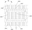
4.本实用新型提供的示例4:包括上述示例3,其中,所述除尘电场阳极包括第一阳极部和第二阳极部,所述第一阳极部靠近除尘电场装置入口,第二阳极部靠近除尘电场装置出口,所述第一阳极部和所述第二阳极部之间设置有至少一个阴极支撑板。4. Example 4 provided by the present invention: including the above example 3, wherein the anode of the dust removal electric field includes a first anode part and a second anode part, the first anode part is close to the inlet of the dust removal electric field device, and the second anode part is close to the inlet of the dust removal electric field device. At the outlet of the dust removal electric field device, at least one cathode support plate is arranged between the first anode part and the second anode part.
5.本实用新型提供的示例5:包括上述示例4,其中,所述除尘电场装置还包括绝缘机构,用于实现所述阴极支撑板和所述除尘电场阳极之间的绝缘。5. Example 5 provided by the present invention: including the above example 4, wherein the dedusting electric field device further includes an insulating mechanism for realizing the insulation between the cathode support plate and the anode of the dedusting electric field.
6.本实用新型提供的示例6:包括上述示例5,其中,所述除尘电场阳极和所述除尘电场阴极之间形成电场流道,所述绝缘机构设置在所述电场流道外。6. Example 6 provided by the present invention includes the above example 5, wherein an electric field flow channel is formed between the dust removal electric field anode and the dust removal electric field cathode, and the insulating mechanism is arranged outside the electric field flow channel.
7.本实用新型提供的示例7:包括上述示例5或6,其中,所述绝缘机构包括绝缘部和隔热部;所述绝缘部的材料采用陶瓷材料或玻璃材料。7. Example 7 provided by the present invention: including the above example 5 or 6, wherein the insulating mechanism includes an insulating part and a heat insulating part; the material of the insulating part is a ceramic material or a glass material.
8.本实用新型提供的示例8:包括上述示例7,其中,所述绝缘部为伞状串陶瓷柱、伞状串玻璃柱、柱状串陶瓷柱或柱状玻璃柱,伞内外或柱内外挂釉。8. Example 8 provided by the present invention: including the above-mentioned example 7, wherein the insulating part is an umbrella-shaped string ceramic column, an umbrella-shaped string glass column, a column-shaped string ceramic column or a columnar glass column, and the inside and outside of the umbrella or the inside and outside of the column are glazed. .
9.本实用新型提供的示例9:包括上述示例8,其中,伞状串陶瓷柱或伞状串玻璃柱的外缘与所述除尘电场阳极的距离大于电场距离1.4倍,伞状串陶瓷柱或伞状串玻璃柱的伞突边间距总和大于伞状串陶瓷柱或伞状串玻璃柱的绝缘间距1.4倍,伞状串陶瓷柱或伞状串玻璃柱的伞边内深总长大于伞状串陶瓷柱或伞状串玻璃柱的绝缘距离1.4倍。9. Example 9 provided by the present invention: including the above example 8, wherein the distance between the outer edge of the umbrella-shaped ceramic column or the umbrella-shaped glass column and the anode of the dust removal electric field is 1.4 times greater than the electric field distance, and the umbrella-shaped ceramic column is Or the sum of the distance between the umbrella flanges of the umbrella-shaped glass string column is 1.4 times greater than the insulation spacing of the umbrella-shaped stringed ceramic column or the umbrella-shaped stringed glass column, and the total length of the inner depth of the umbrella edge of the umbrella-shaped stringed ceramic column or the umbrella-shaped glass string column is greater than that of the umbrella-shaped string. The insulation distance of stringed ceramic columns or umbrella-shaped stringed glass columns is 1.4 times.
10.本实用新型提供的示例10:包括上述示例4至9中的任一项,其中,所述第一阳极部的长度是所述除尘电场阳极长度的1/10至1/4、1/4至1/3、1/3至1/2、1/2至2/3、2/3至3/4,或3/4至9/10。10. Example 10 provided by the present invention: including any one of the above examples 4 to 9, wherein the length of the first anode part is 1/10 to 1/4, 1/1/10 of the length of the anode of the dust removal electric field 4 to 1/3, 1/3 to 1/2, 1/2 to 2/3, 2/3 to 3/4, or 3/4 to 9/10.
11.本实用新型提供的示例11:包括上述示例4至10中的任一项,其中,所述第一阳极部的长度是足够的长,以清除部分灰尘,减少积累在所述绝缘机构和所述阴极支撑板上的灰尘,减少灰尘造成的电击穿。11. Example 11 provided by the present invention: including any one of the above examples 4 to 10, wherein the length of the first anode portion is long enough to remove part of the dust and reduce accumulation in the insulating mechanism and The dust on the cathode support plate reduces the electrical breakdown caused by the dust.
12.本实用新型提供的示例12:包括上述示例4至11中的任一项,其中,所述第二阳极部包括积尘段和预留积尘段。12. Example 12 provided by the present invention: including any one of the above examples 4 to 11, wherein the second anode part includes a dust accumulation section and a reserved dust accumulation section.
13.本实用新型提供的示例13:包括上述示例3至12中的任一项,其中,所述除尘电场阴极包括至少一根电极棒。13. Example 13 provided by the present invention: including any one of the above examples 3 to 12, wherein the dust removal electric field cathode comprises at least one electrode rod.
14.本实用新型提供的示例14:包括上述示例13,其中,所述电极棒的直径不大于3mm。14. Example 14 provided by the present invention: including the above Example 13, wherein the diameter of the electrode rod is not greater than 3 mm.
15.本实用新型提供的示例15:包括上述示例13或14,其中,所述电极棒的形状呈针状、多角状、毛刺状、螺纹杆状或柱状。15. Example 15 provided by the present invention: including the above-mentioned example 13 or 14, wherein the shape of the electrode rod is a needle shape, a polygonal shape, a burr shape, a threaded rod shape or a column shape.
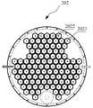
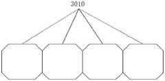
16.本实用新型提供的示例16:包括上述示例3至15中的任一项,其中,所述除尘电场阳极由中空的管束组成。16. Example 16 provided by the present invention: including any one of the above examples 3 to 15, wherein the dust removal electric field anode is composed of a hollow tube bundle.
17.本实用新型提供的示例17:包括上述示例16,其中,所述除尘电场阳极管束的中空的截面采用圆形或多边形。17. Example 17 provided by the present invention: including the above Example 16, wherein the hollow cross-section of the anode tube bundle of the dust removal electric field adopts a circle or a polygon.
18.本实用新型提供的示例18:包括上述示例17,其中,所述多边形为六边形。18. Example 18 provided by the present invention: including the above Example 17, wherein the polygon is a hexagon.
19.本实用新型提供的示例19:包括上述示例16至18中的任一项,其中,所述除尘电场阳极的管束呈蜂窝状。19. Example 19 provided by the present invention: including any one of the above examples 16 to 18, wherein the tube bundle of the dust removal electric field anode is in a honeycomb shape.
20.本实用新型提供的示例20:包括上述示例3至19中的任一项,其中,所述除尘电场阴极穿射于所述除尘电场阳极内。20. Example 20 provided by the present invention: including any one of the above examples 3 to 19, wherein the cathode of the dust removal electric field penetrates into the anode of the dust removal electric field.
21.本实用新型提供的示例21:包括上述示例3至20中的任一项,其中,当电场积尘到一定程度时,所述除尘电场装置进行除碳黑处理。21. Example 21 provided by the present invention: including any one of the above examples 3 to 20, wherein when the electric field dust accumulates to a certain extent, the electric field device for dust removal performs carbon black removal treatment.
22.本实用新型提供的示例22:包括上述示例21,其中,所述除尘电场装置检测电场电流来确定是否积尘到一定程度,需要进行除碳黑处理。22. Example 22 provided by the present invention: including the above-mentioned example 21, wherein the electric field device for dust removal detects the electric field current to determine whether the dust accumulation reaches a certain level, and carbon black removal treatment is required.
23.本实用新型提供的示例23:包括上述示例21或22,其中,所述除尘电场装置增高电场电压来进行除碳黑处理。23. Example 23 provided by the present invention: including the above-mentioned example 21 or 22, wherein the dust removal electric field device increases the electric field voltage to perform carbon black removal treatment.
24.本实用新型提供的示例24:包括上述示例21或22,其中,所述除尘电场装置利用电场反电晕放电现象来进行除碳黑处理。24. Example 24 provided by the present invention: including the above-mentioned example 21 or 22, wherein the dust removal electric field device utilizes the phenomenon of electric field reverse corona discharge to perform carbon black removal treatment.
25.本实用新型提供的示例25:包括上述示例21或22,其中,所述除尘电场装置利用电场反电晕放电现象,增高电压,限制入注电流,使发生在阳极积碳位置的急剧放电产生等离子,所述等离子使碳黑有机成分深度氧化,高分子键断裂,形成小分子二氧化碳和水,来进行除碳黑处理。25. Example 25 provided by the present utility model: including the above-mentioned example 21 or 22, wherein the dedusting electric field device utilizes the phenomenon of reverse corona discharge in the electric field, increases the voltage, limits the injection current, and causes a sharp discharge at the anode carbon deposition position. Plasma is generated, which deeply oxidizes the organic components of carbon black, breaks polymer bonds, and forms small molecules of carbon dioxide and water for carbon black removal treatment.
26.本实用新型提供的示例26:包括上述示例3至25中的任一项,其中,所述除尘电场阳极长度为10-90mm,所述除尘电场阴极长度为10-90mm。26. Example 26 provided by the present invention: including any one of the above examples 3 to 25, wherein the length of the anode of the dust removal electric field is 10-90 mm, and the length of the cathode of the dust removal electric field is 10-90 mm.
27.本实用新型提供的示例27:包括上述示例26,其中,当电场温度为200℃时,对应的集尘效率为99.9%。27. Example 27 provided by the present invention: including the above example 26, wherein when the electric field temperature is 200° C., the corresponding dust collection efficiency is 99.9%.
28.本实用新型提供的示例28:包括上述示例26或27,其中,当电场温度为400℃时,对应的集尘效率为90%。28. Example 28 provided by the present invention: including the above example 26 or 27, wherein when the electric field temperature is 400° C., the corresponding dust collection efficiency is 90%.
29.本实用新型提供的示例29:包括上述示例26至28中的任一项,其中,当电场温度为 500℃时,对应的集尘效率为50%。29. Example 29 provided by the present invention: including any one of the above examples 26 to 28, wherein, when the electric field temperature is 500°C, the corresponding dust collection efficiency is 50%.
30.本实用新型提供的示例30:包括上述示例3至29中的任一项,其中,所述除尘电场装置还包括辅助电场单元,用于产生与所述电离除尘电场不平行的辅助电场。30. Example 30 provided by the present invention: including any one of the above examples 3 to 29, wherein the dedusting electric field device further comprises an auxiliary electric field unit for generating an auxiliary electric field that is not parallel to the ionization dedusting electric field.
31.本实用新型提供的示例31:包括上述示例3至29中的任一项,其中,所述除尘电场装置还包括辅助电场单元,所述电离除尘电场包括流道,所述辅助电场单元用于产生与所述流道不垂直的辅助电场。31. Example 31 provided by the present invention: including any one of the above examples 3 to 29, wherein the dedusting electric field device further includes an auxiliary electric field unit, the ionization dedusting electric field includes a flow channel, and the auxiliary electric field unit is to generate an auxiliary electric field that is not perpendicular to the flow channel.
32.本实用新型提供的示例32:包括上述示例30或31,其中,所述辅助电场单元包括第一电极,所述辅助电场单元的第一电极设置在或靠近所述电离除尘电场的进口。32. Example 32 provided by the present invention: including the above example 30 or 31, wherein the auxiliary electric field unit includes a first electrode, and the first electrode of the auxiliary electric field unit is disposed at or near the inlet of the ionization and dust removal electric field.
33.本实用新型提供的示例33:包括上述示例32,其中,所述第一电极为阴极。33. Example 33 provided by the present invention: including the above Example 32, wherein the first electrode is a cathode.
34.本实用新型提供的示例34:包括上述示例32或33,其中,所述辅助电场单元的第一电极是所述除尘电场阴极的延伸。34. Example 34 provided by the present invention: including the above example 32 or 33, wherein the first electrode of the auxiliary electric field unit is an extension of the cathode of the dust removal electric field.
35.本实用新型提供的示例35:包括上述示例34,其中,所述辅助电场单元的第一电极与所述除尘电场阳极具有夹角α,且0°<α≤125°、或45°≤α≤125°、或60°≤α≤100°、或α=90°。35. Example 35 provided by the present invention: including the above example 34, wherein the first electrode of the auxiliary electric field unit and the dust removal electric field anode have an included angle α, and 0°<α≤125°, or 45°≤ α≤125°, or 60°≤α≤100°, or α=90°.
36.本实用新型提供的示例36:包括上述示例30至35中的任一项,其中,所述辅助电场单元包括第二电极,所述辅助电场单元的第二电极设置在或靠近所述电离除尘电场的出口。36. Example 36 provided by the present invention: including any one of the above examples 30 to 35, wherein the auxiliary electric field unit includes a second electrode, and the second electrode of the auxiliary electric field unit is disposed at or near the ionization The outlet of the dust removal field.
37.本实用新型提供的示例37:包括上述示例36,其中,所述第二电极为阳极。37. Example 37 provided by the present invention: including the above Example 36, wherein the second electrode is an anode.
38.本实用新型提供的示例38:包括上述示例36或37,其中,所述辅助电场单元的第二电极是所述除尘电场阳极的延伸。38. Example 38 provided by the present invention: including the above example 36 or 37, wherein the second electrode of the auxiliary electric field unit is an extension of the anode of the dust removal electric field.
39.本实用新型提供的示例39:包括上述示例38,其中,所述辅助电场单元的第二电极与所述除尘电场阴极具有夹角α,且0°<α≤125°、或45°≤α≤125°、或60°≤α≤100°、或α=90°。39. Example 39 provided by the present invention: including the above example 38, wherein the second electrode of the auxiliary electric field unit and the cathode of the dust removal electric field have an included angle α, and 0°<α≤125°, or 45°≤ α≤125°, or 60°≤α≤100°, or α=90°.
40.本实用新型提供的示例40:包括上述示例30至33、36和37中的任一项,其中,所述辅助电场的电极与所述电离除尘电场的电极独立设置。40. Example 40 provided by the present invention: including any one of the above examples 30 to 33, 36 and 37, wherein the electrodes of the auxiliary electric field are arranged independently of the electrodes of the ionization and dust removal electric field.
41.本实用新型提供的示例41:包括上述示例3至40中的任一项,其中,所述除尘电场阳极的积尘面积与所述除尘电场阴极的放电面积的比为1.667:1-1680:1。41. Example 41 provided by the present invention: including any one of the above examples 3 to 40, wherein the ratio of the dust accumulation area of the dust removal electric field anode to the discharge area of the dust removal electric field cathode is 1.667:1-1680 :1.
42.本实用新型提供的示例42:包括上述示例3至40中的任一项,其中,所述除尘电场阳极的积尘面积与所述除尘电场阴极的放电面积的比为6.67:1-56.67:1。42. Example 42 provided by the present invention: including any one of the above examples 3 to 40, wherein the ratio of the dust accumulation area of the anode of the dust removal electric field to the discharge area of the cathode of the dust removal electric field is 6.67:1-56.67 :1.
43.本实用新型提供的示例43:包括上述示例3至42中的任一项,其中,所述除尘电场阴极直径为1-3毫米,所述除尘电场阳极与所述除尘电场阴极的极间距为2.5-139.9毫米;所述除尘电场阳极的积尘面积与所述除尘电场阴极的放电面积的比为1.667:1-1680:1。43. Example 43 provided by the present invention: including any one of the above examples 3 to 42, wherein the diameter of the dust removal electric field cathode is 1-3 mm, and the distance between the anode of the dust removal electric field and the cathode of the dust removal electric field is 1-3 mm. is 2.5-139.9 mm; the ratio of the dust accumulation area of the anode of the dust removal electric field to the discharge area of the cathode of the dust removal electric field is 1.667:1-1680:1.
44.本实用新型提供的示例44:包括上述示例3至42中的任一项,其中,所述除尘电场阳极和所述除尘电场阴极的极间距小于150mm。44. Example 44 provided by the present invention: including any one of the above examples 3 to 42, wherein the distance between the electrodes of the dust removal electric field anode and the dust removal electric field cathode is less than 150 mm.
45.本实用新型提供的示例45:包括上述示例3至42中的任一项,其中,所述除尘电场阳极与所述除尘电场阴极的极间距为2.5-139.9mm。45. Example 45 provided by the present invention: including any one of the above examples 3 to 42, wherein the distance between the anode of the dust removal electric field and the cathode of the dust removal electric field is 2.5-139.9 mm.
46.本实用新型提供的示例46:包括上述示例3至42中的任一项,其中,所述除尘电场阳极与所述除尘电场阴极的极间距为5-100mm。46. Example 46 provided by the present invention: including any one of the above examples 3 to 42, wherein the distance between the anode of the dust removal electric field and the cathode of the dust removal electric field is 5-100 mm.
47.本实用新型提供的示例47:包括上述示例3至46中的任一项,其中,所述除尘电场阳极长度为10-180mm。47. Example 47 provided by the present invention: including any one of the above examples 3 to 46, wherein the length of the anode of the dust removal electric field is 10-180 mm.
48.本实用新型提供的示例48:包括上述示例3至46中的任一项,其中,所述除尘电场阳极长度为60-180mm。48. Example 48 provided by the present invention: including any one of the above examples 3 to 46, wherein the length of the anode of the dust removal electric field is 60-180 mm.
49.本实用新型提供的示例49:包括上述示例3至48中的任一项,其中,所述除尘电场阴极长度为30-180mm。49. Example 49 provided by the present invention: including any one of the above examples 3 to 48, wherein the length of the cathode of the dust removal electric field is 30-180 mm.
50.本实用新型提供的示例50:包括上述示例3至48中的任一项,其中,所述除尘电场阴极长度为54-176mm。50. Example 50 provided by the present invention: including any one of the above examples 3 to 48, wherein the length of the cathode of the dust removal electric field is 54-176 mm.
51.本实用新型提供的示例51:包括上述示例41至50中的任一项,其中,当运行时,所述电离除尘电场的耦合次数≤3。51. Example 51 provided by the present invention: including any one of the above examples 41 to 50, wherein, when running, the coupling times of the ionization and dust removal electric field is less than or equal to 3.
52.本实用新型提供的示例52:包括上述示例30至50中的任一项,其中,当运行时,所述电离除尘电场的耦合次数≤3。52. Example 52 provided by the present invention: including any one of the above-mentioned examples 30 to 50, wherein, when running, the coupling times of the ionization and dust removal electric field is less than or equal to 3.
53.本实用新型提供的示例53:包括上述示例3至52中的任一项,其中,所述电离除尘电场电压的取值范围为1kv-50kv。53. Example 53 provided by the present utility model: including any one of the above examples 3 to 52, wherein the value of the electric field voltage for ionization and dust removal ranges from 1kv to 50kv.
54.本实用新型提供的示例54:包括上述示例3至53中的任一项,其中,所述除尘电场装置还包括若干连接壳体,串联电场级通过所述连接壳体连接。54. Example 54 provided by the present invention: including any one of the above examples 3 to 53, wherein the dedusting electric field device further comprises a plurality of connection casings, and the series electric field stages are connected through the connection casings.
55.本实用新型提供的示例55:包括上述示例54,其中,相邻的电场级的距离大于所述极间距的1.4倍。55. Example 55 provided by the present invention: including example 54 above, wherein the distance between adjacent electric field levels is greater than 1.4 times the pole spacing.
56.本实用新型提供的示例56:包括上述示例3至55中的任一项,其中,所述除尘电场装置还包括前置电极,所述前置电极在所述除尘电场装置入口与所述除尘电场阳极和所述除尘电场阴极形成的电离除尘电场之间。56. Example 56 provided by the present invention: including any one of the above-mentioned examples 3 to 55, wherein the dedusting electric field device further comprises a pre-electrode, and the pre-electrode is connected to the inlet of the dedusting electric field device with the dedusting electric field device. between the ionization dust removal field formed by the dust removal electric field anode and the dust removal field cathode.
57.本实用新型提供的示例57:包括上述示例56,其中,所述前置电极呈点状、线状、网状、孔板状、板状、针棒状、球笼状、盒状、管状、物质自然形态、或物质加工形态。57. Example 57 provided by the present invention: including the above-mentioned example 56, wherein the front electrode is in the shape of a point, a line, a mesh, an orifice, a plate, a needle bar, a ball cage, a box, or a tube. , the natural form of matter, or the processed form of matter.
58.本实用新型提供的示例58:包括上述示例56或57,其中,所述前置电极上设有通孔。58. Example 58 provided by the present invention: including the above-mentioned example 56 or 57, wherein the front electrode is provided with a through hole.
59.本实用新型提供的示例59:包括上述示例58,其中,所述通孔呈多角形、圆形、椭圆形、正方形、长方形、梯形、或菱形。59. Example 59 provided by the present invention: including the above example 58, wherein the through hole is in the shape of a polygon, a circle, an ellipse, a square, a rectangle, a trapezoid, or a rhombus.
60.本实用新型提供的示例60:包括上述示例58或59,其中,所述通孔的大小为0.1-3 毫米。60. Example 60 provided by the present invention: including the above example 58 or 59, wherein the size of the through hole is 0.1-3 mm.
61.本实用新型提供的示例61:包括上述示例56至60中的任一项,其中,所述前置电极为固体、液体、气体分子团、或等离子体中的一种或多种形态的组合。61. Example 61 provided by the present invention: including any one of the above-mentioned examples 56 to 60, wherein the pre-electrode is in one or more forms of solid, liquid, gas molecule group, or plasma. combination.
62.本实用新型提供的示例62:包括上述示例56至61中的任一项,其中,所述前置电极为导电混合态物质、生物体自然混合导电物质、或物体人工加工形成导电物质。62. Example 62 provided by the present invention: including any one of the above-mentioned examples 56 to 61, wherein the front electrode is a conductive mixed state substance, a biologically mixed conductive substance, or an object artificially processed to form a conductive substance.
63.本实用新型提供的示例63:包括上述示例56至62中的任一项,其中,所述前置电极为304钢或石墨。63. Example 63 provided by the present invention: including any one of the above examples 56 to 62, wherein the front electrode is 304 steel or graphite.
64.本实用新型提供的示例64:包括上述示例56至62中的任一项,其中,所述前置电极为含离子导电液体。64. Example 64 provided by the present invention: including any one of the above examples 56 to 62, wherein the front electrode is an ion-containing conductive liquid.
65.本实用新型提供的示例65:包括上述示例56至64中的任一项,其中,在工作时,在带污染物的气体进入所述除尘电场阴极、除尘电场阳极形成的电离除尘电场之前,且带污染物的气体通过所述前置电极时,所述前置电极使气体中的污染物带电。65. Example 65 provided by the present invention: including any one of the above examples 56 to 64, wherein, during operation, before the gas with pollutants enters the ionization and dust removal field formed by the dust removal electric field cathode and the dust removal electric field anode , and when the gas with pollutants passes through the front electrode, the front electrode charges the pollutants in the gas.
66.本实用新型提供的示例66:包括上述示例65,其中,当带污染物的气体进入所述电离除尘电场时,所述除尘电场阳极给带电的污染物施加吸引力,使污染物向所述除尘电场阳极移动,直至污染物附着在所述除尘电场阳极上。66. Example 66 provided by the present invention: including the above-mentioned example 65, wherein when the gas with pollutants enters the ionization and dust removal electric field, the dust removal field anode exerts an attractive force on the charged pollutants, so that the pollutants are attracted to all the pollutants. The dust removal electric field anode moves until pollutants adhere to the dust removal electric field anode.
67.本实用新型提供的示例67:包括上述示例65或66,其中,所述前置电极将电子导入污染物,电子在位于所述前置电极和所述除尘电场阳极之间的污染物之间进行传递,使更多污染物带电。67. Example 67 provided by the present invention: including the above-mentioned example 65 or 66, wherein the front electrode guides electrons into pollutants, and the electrons are located between the pollutants located between the front electrode and the dust removal electric field anode. transfer between them, making more contaminants charged.
68.本实用新型提供的示例68:包括上述示例64至66中的任一项,其中,所述前置电极和所述除尘电场阳极之间通过污染物传导电子、并形成电流。68. Example 68 provided by the present invention: including any one of the above examples 64 to 66, wherein electrons are conducted between the pre-electrode and the anode of the dust removal electric field through pollutants, and an electric current is formed.
69.本实用新型提供的示例69:包括上述示例65至68中的任一项,其中,所述前置电极通过与污染物接触的方式使污染物带电。69. Example 69 provided by the present invention: including any one of the above examples 65 to 68, wherein the pre-electrode charges the pollutants by contacting the pollutants.
70.本实用新型提供的示例70:包括上述示例65至69中的任一项,其中,所述前置电极通过能量波动的方式使污染物带电。70. Example 70 provided by the present invention: including any one of the above examples 65 to 69, wherein the pre-electrode charges the pollutants by means of energy fluctuations.
71.本实用新型提供的示例71:包括上述示例65至70中的任一项,其中,所述前置电极上设有通孔。71. Example 71 provided by the present invention: including any one of the above examples 65 to 70, wherein the front electrode is provided with a through hole.
72.本实用新型提供的示例72:包括上述示例56至71中的任一项,其中,所述前置电极呈线状,所述除尘电场阳极呈面状。72. Example 72 provided by the present invention: including any one of the above examples 56 to 71, wherein the front electrode is in the shape of a line, and the anode of the dust removal electric field is in the shape of a plane.
73.本实用新型提供的示例73:包括上述示例56至72中的任一项,其中,所述前置电极垂直于所述除尘电场阳极。73. Example 73 provided by the present invention: including any one of the above examples 56 to 72, wherein the front electrode is perpendicular to the dust removal electric field anode.
74.本实用新型提供的示例74:包括上述示例56至73中的任一项,其中,所述前置电极与所述除尘电场阳极相平行。74. Example 74 provided by the present invention: including any one of the above examples 56 to 73, wherein the front electrode is parallel to the anode of the dust removal electric field.
75.本实用新型提供的示例75:包括上述示例56至74中的任一项,其中,所述前置电极呈曲线状或圆弧状。75. Example 75 provided by the present invention: including any one of the above examples 56 to 74, wherein the front electrode is in the shape of a curve or an arc.
76.本实用新型提供的示例76:包括上述示例56至75中的任一项,其中,所述前置电极采用金属丝网。76. Example 76 provided by the present invention: including any one of the above examples 56 to 75, wherein the front electrode adopts a wire mesh.
77.本实用新型提供的示例77:包括上述示例56至76中的任一项,其中,所述前置电极与所述除尘电场阳极之间的电压不同于所述除尘电场阴极与所述除尘电场阳极之间的电压。77. Example 77 provided by the present invention: including any one of the above examples 56 to 76, wherein the voltage between the front electrode and the anode of the dust removal electric field is different from that of the dust removal electric field cathode and the dust removal electric field Electric field voltage between anodes.
78.本实用新型提供的示例78:包括上述示例56至77中的任一项,其中,所述前置电极与所述除尘电场阳极之间的电压小于起始起晕电压。78. Example 78 provided by the present invention: including any one of the above examples 56 to 77, wherein the voltage between the front electrode and the anode of the dust removal electric field is less than the initial corona initiation voltage.
79.本实用新型提供的示例79:包括上述示例56至78中的任一项,其中,所述前置电极与所述除尘电场阳极之间的电压为0.1kv-2kv/mm。79. Example 79 provided by the present invention: including any one of the above examples 56 to 78, wherein the voltage between the front electrode and the anode of the dust removal electric field is 0.1kv-2kv/mm.
80.本实用新型提供的示例80:包括上述示例56至79中的任一项,其中,所述除尘电场装置包括排气流道,所述前置电极位于所述排气流道中;所述前置电极的截面面积与排气流道的截面面积比为99%-10%、或90-10%、或80-20%、或70-30%、或60-40%、或50%。80. Example 80 provided by the present invention: including any one of the above examples 56 to 79, wherein the dust removal electric field device comprises an exhaust flow channel, and the front electrode is located in the exhaust flow channel; the The ratio of the cross-sectional area of the front electrode to the cross-sectional area of the exhaust flow channel is 99%-10%, or 90-10%, or 80-20%, or 70-30%, or 60-40%, or 50%.
81.本实用新型提供的示例81:包括上述示例3至80中的任一项,其中,所述除尘电场装置包括驻极体元件。81. Example 81 provided by the present invention: including any one of the above examples 3 to 80, wherein the dedusting electric field device comprises an electret element.
82.本实用新型提供的示例82:包括上述示例81,其中,所述除尘电场阳极和所述除尘电场阴极接通电源时,所述驻极体元件在所述电离除尘电场中。82. Example 82 provided by the present invention: including the above-mentioned example 81, wherein the electret element is in the ionization and dust removal field when the power supply of the dust removal electric field anode and the dust removal field cathode are connected.
83.本实用新型提供的示例83:包括上述示例81或82,其中,所述驻极体元件靠近所述除尘电场装置出口,或者,所述驻极体元件设于所述除尘电场装置出口。83. Example 83 provided by the present invention: including the above-mentioned example 81 or 82, wherein the electret element is close to the outlet of the dedusting electric field device, or the electret element is provided at the outlet of the dedusting electric field device.
84.本实用新型提供的示例84:包括上述示例81至83中的任一项,其中,所述除尘电场阳极和所述除尘电场阴极形成排气流道,所述驻极体元件设于所述排气流道中。84. Example 84 provided by the present invention: including any one of the above examples 81 to 83, wherein the dust removal electric field anode and the dust removal electric field cathode form an exhaust flow channel, and the electret element is provided in the in the exhaust runner.
85.本实用新型提供的示例85:包括上述示例84,其中,所述排气流道包括排气流道出口,所述驻极体元件靠近所述排气流道出口,或者,所述驻极体元件设于所述排气流道出口。85. Example 85 provided by the present invention: including the above example 84, wherein the exhaust runner includes an exhaust runner outlet, and the electret element is adjacent to the exhaust runner outlet, or the electret The polar body element is arranged at the outlet of the exhaust runner.
86.本实用新型提供的示例86:包括上述示例84或85,其中,所述驻极体元件于所述排气流道中的横截面占排气流道横截面5%-100%。86. Example 86 provided by the present invention: including the above example 84 or 85, wherein the cross section of the electret element in the exhaust flow channel accounts for 5%-100% of the cross section of the exhaust flow channel.
87.本实用新型提供的示例87:包括上述示例86,其中,所述驻极体元件于所述排气流道中的横截面占排气流道横截面10%-90%、20%-80%、或40%-60%。87. Example 87 provided by the present invention: including the above example 86, wherein the cross section of the electret element in the exhaust flow channel accounts for 10%-90%, 20%-80% of the cross section of the exhaust flow channel %, or 40%-60%.
88.本实用新型提供的示例88:包括上述示例81至87中的任一项,其中,所述电离除尘电场给所述驻极体元件充电。88. Example 88 provided by the present invention: including any one of the above examples 81 to 87, wherein the ionizing dust removal electric field charges the electret element.
89.本实用新型提供的示例89:包括上述示例81至88中的任一项,其中,所述驻极体元件具有多孔结构。89. Example 89 provided by the present invention: including any one of the above Examples 81 to 88, wherein the electret element has a porous structure.
90.本实用新型提供的示例90:包括上述示例81至89中的任一项,其中,所述驻极体元件为织品。90. Example 90 provided by the present invention: including any one of the above examples 81 to 89, wherein the electret element is a fabric.
91.本实用新型提供的示例91:包括上述示例81至90中的任一项,其中,所述除尘电场阳极内部为管状,所述驻极体元件外部为管状,所述驻极体元件外部套设于所述除尘电场阳极内部。91. Example 91 provided by the present invention: including any one of the above examples 81 to 90, wherein the inside of the dust removal electric field anode is tubular, the outside of the electret element is tubular, and the outside of the electret element is tubular It is sleeved inside the anode of the dust removal electric field.
92.本实用新型提供的示例92:包括上述示例81至91中的任一项,其中,所述驻极体元件与所述除尘电场阳极为可拆卸式连接。92. Example 92 provided by the present invention: including any one of the above-mentioned examples 81 to 91, wherein the electret element and the anode of the dust removal electric field are detachably connected.
93.本实用新型提供的示例93:包括上述示例81至92中的任一项,其中,所述驻极体元件的材料包括具有驻极性能的无机化合物。93. Example 93 provided by the present invention: including any one of the above examples 81 to 92, wherein the material of the electret element comprises an inorganic compound having electret properties.
94.本实用新型提供的示例94:包括上述示例93,其中,所述无机化合物选自含氧化合物、含氮化合物或玻璃纤维中的一种或多种组合。94. Example 94 provided by the present invention: including the above Example 93, wherein the inorganic compound is selected from one or more combinations of oxygen-containing compounds, nitrogen-containing compounds or glass fibers.
95.本实用新型提供的示例95:包括上述示例94,其中,所述含氧化合物选自金属基氧化物、含氧复合物、含氧的无机杂多酸盐中的一种或多种组合。95. Example 95 provided by the present invention: including the above-mentioned example 94, wherein the oxygen-containing compound is selected from one or more combinations of metal-based oxides, oxygen-containing composites, and oxygen-containing inorganic heteropoly acid salts .
96.本实用新型提供的示例96:包括上述示例95,其中,所述金属基氧化物选自氧化铝、氧化锌、氧化锆、氧化钛、氧化钡、氧化钽、氧化硅、氧化铅、氧化锡中的一种或多种组合。96. Example 96 provided by the present invention: including example 95 above, wherein the metal-based oxide is selected from the group consisting of aluminum oxide, zinc oxide, zirconium oxide, titanium oxide, barium oxide, tantalum oxide, silicon oxide, lead oxide, oxide One or more combinations of tin.
97.本实用新型提供的示例97:包括上述示例95,其中,所述金属基氧化物为氧化铝。97. Example 97 provided by the present invention: including the above Example 95, wherein the metal-based oxide is alumina.
98.本实用新型提供的示例98:包括上述示例95,其中,所述含氧复合物选自钛锆复合氧化物或钛钡复合氧化物中的一种或多种组合。98. Example 98 provided by the present invention: including the above Example 95, wherein the oxygen-containing composite is selected from one or more combinations of titanium-zirconium composite oxide or titanium-barium composite oxide.
99.本实用新型提供的示例99:包括上述示例95,其中,所述含氧的无机杂多酸盐选自钛酸锆、锆钛酸铅或钛酸钡中的一种或多种组合。99. Example 99 provided by the present invention: including the above Example 95, wherein the oxygen-containing inorganic heteropoly acid salt is selected from one or more combinations of zirconium titanate, lead zirconate titanate or barium titanate.
100.本实用新型提供的示例100:包括上述示例94,其中,所述含氮化合物为氮化硅。100. Example 100 provided by the present invention: including the above Example 94, wherein the nitrogen-containing compound is silicon nitride.
101.本实用新型提供的示例101:包括上述示例81至100中的任一项,其中,所述驻极体元件的材料包括具有驻极性能的有机化合物。101. Example 101 provided by the present invention: including any one of the above examples 81 to 100, wherein the material of the electret element includes an organic compound having electret properties.
102.本实用新型提供的示例102:包括上述示例101,其中,所述有机化合物选自氟聚合物、聚碳酸酯、PP、PE、PVC、天然蜡、树脂、松香中的一种或多种组合。102. Example 102 provided by the present invention: including the above example 101, wherein the organic compound is selected from one or more of fluoropolymer, polycarbonate, PP, PE, PVC, natural wax, resin, and rosin combination.
103.本实用新型提供的示例103:包括上述示例102,其中,所述氟聚合物选自聚四氟乙烯、聚全氟乙丙烯、可溶性聚四氟乙烯、聚偏氟乙烯中的一种或多种组合。103. Example 103 provided by the present invention: including the above example 102, wherein the fluoropolymer is selected from one of polytetrafluoroethylene, polyperfluoroethylene propylene, soluble polytetrafluoroethylene, polyvinylidene fluoride, or Various combinations.
104.本实用新型提供的示例104:包括上述示例102,其中,所述氟聚合物为聚四氟乙烯。104. Example 104 provided by the present invention: including the above example 102, wherein the fluoropolymer is polytetrafluoroethylene.
105.本实用新型提供的示例105:包括上述示例2至104中的任一项,其中,还包括均风装置。105. Example 105 provided by the present invention: including any one of the above examples 2 to 104, and further including an air equalizing device.
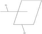
106.本实用新型提供的示例106:包括上述示例105,其中,所述均风装置在所述除尘系统入口与所述除尘电场阳极和所述除尘电场阴极形成的电离除尘电场之间,当所述除尘电场阳极为四方体时,述均风装置包括:设置于所述除尘电场阳极一侧边的进气管和设置于另一侧边的出气管;其中,所述进气管与所述出气管相对立。106. Example 106 provided by the present invention: including the above-mentioned example 105, wherein the air equalization device is between the inlet of the dust removal system and the ionization dust removal field formed by the dust removal field anode and the dust removal field cathode, when all When the anode of the dust removal electric field is a tetrahedron, the air equalization device includes: an air inlet pipe arranged on one side of the dust removal electric field anode and an air outlet pipe arranged on the other side; wherein, the air inlet pipe and the air outlet pipe Opposite.
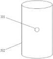
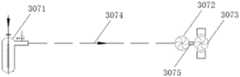
107.本实用新型提供的示例107:包括上述示例105,其中,所述均风装置在所述除尘系统入口与所述除尘电场阳极和所述除尘电场阴极形成的电离除尘电场之间,当所述除尘电场阳极为圆柱体时,所述均风装置由若干可旋转的均风叶片组成。107. Example 107 provided by the present invention: including the above-mentioned example 105, wherein the air equalizing device is between the inlet of the dust removal system and the ionization dust removal field formed by the dust removal field anode and the dust removal field cathode, when all When the anode of the dust removal electric field is a cylinder, the air equalization device is composed of several rotatable air equalization blades.
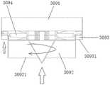
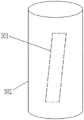
108.本实用新型提供的示例108:包括上述示例105,其中,所述均风装置第一文氏板均风机构和设置于所述除尘电场阳极的出气端的第二文氏板均风机构,所述第一文氏板均风机构上开设有进气孔,所述第二文氏板均风机构上开设有出气孔,所述进气孔与所述出气孔错位排布,且正面进气侧面出气,形成旋风结构。108. Example 108 provided by the present utility model: including the above-mentioned example 105, wherein the first venturi plate wind equalizing mechanism of the air equalizing device and the second venturi plate wind equalizing mechanism arranged at the gas outlet end of the anode of the dust removal electric field, The air equalizing mechanism of the first venturi plate is provided with an air inlet hole, and the air equalizing mechanism of the second venturi plate is provided with an air outlet hole. The air is released from the side, forming a cyclone structure.
109.本实用新型提供的示例109:包括上述示例2至108中的任一项,其中,还包括补氧装置,用于在所述电离除尘电场之前添加包括氧气的气体。109. Example 109 provided by the present invention: including any one of the above examples 2 to 108, wherein an oxygen supplement device is further included for adding a gas including oxygen before the ionization and dust removal electric field.
110.本实用新型提供的示例110:包括上述示例109,其中,所述补氧装置通过单纯增氧、通入外界空气、通入压缩空气和/或通入臭氧的方式添加氧气。110. Example 110 provided by the present invention: including the above example 109, wherein the oxygen supplement device adds oxygen by simply adding oxygen, introducing outside air, introducing compressed air and/or introducing ozone.
111.本实用新型提供的示例111:包括上述示例109或110,其中,至少根据排气颗粒含量决定补氧量。111. Example 111 provided by the present invention: including the above-mentioned example 109 or 110, wherein the oxygen supplementation amount is determined at least according to the content of exhaust particles.
112.本实用新型提供的示例112:包括上述示例2至111中的任一项,其中,还包括除水装置,用于在所述除尘电场装置入口之前去除液体水。112. Example 112 provided by the present invention: including any one of the above examples 2 to 111, and further comprising a water removal device for removing liquid water before the inlet of the dust removal electric field device.
113.本实用新型提供的示例113:包括上述示例112,其中,当排气温度低于一定温度时,所述除水装置脱除排气中的液体水。113. Example 113 provided by the present invention: including the above example 112, wherein, when the exhaust gas temperature is lower than a certain temperature, the water removal device removes liquid water in the exhaust gas.
114.本实用新型提供的示例114:包括上述示例113,其中,所述一定温度在90℃以上、 100℃以下。114. Example 114 provided by the present invention: including the above example 113, wherein the certain temperature is above 90°C and below 100°C.
115.本实用新型提供的示例115:包括上述示例113,其中,所述一定温度在80℃以上、 90℃以下。115. Example 115 provided by the present invention: including the above example 113, wherein the certain temperature is above 80°C and below 90°C.
116.本实用新型提供的示例116:包括上述示例113,其中,所述一定温度为80℃以下。116. Example 116 provided by the present invention: including the above example 113, wherein the certain temperature is below 80°C.
117.本实用新型提供的示例117:包括上述示例112至116,其中,所述除水装置为电凝装置。117. Example 117 provided by the present invention: including the above examples 112 to 116, wherein the water removal device is an electrocoagulation device.
118.本实用新型提供的示例118:包括上述示例2至117中的任一项,其中,还包括降温装置,用于在所述除尘电场装置入口之前降低排气温度。118. Example 118 provided by the present invention: including any one of the above examples 2 to 117, and further comprising a cooling device for lowering the temperature of the exhaust gas before the inlet of the dust removal electric field device.
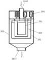
119.本实用新型提供的示例119:包括上述示例118,其中,所述降温装置包括换热单元,用于与排气进行热交换,以将换热单元中液态的换热介质加热成气态的换热介质。119. Example 119 provided by the present invention: including the above example 118, wherein the cooling device includes a heat exchange unit for exchanging heat with the exhaust gas, so as to heat the liquid heat exchange medium in the heat exchange unit into a gaseous one. heat exchange medium.
120.本实用新型提供的示例120:包括上述示例119,其中,所述换热单元包括:120. Example 120 provided by the present invention: including the above example 119, wherein the heat exchange unit includes:
排气通过腔,与排气管路相连通,所述排气通过腔用于供排气通过;The exhaust gas passes through the cavity and is communicated with the exhaust pipeline, and the exhaust gas passes through the cavity for supplying the exhaust gas to pass through;
介质气化腔,所述介质气化腔用于将液态换热介质与排气发生热交换后转化成气态。The medium gasification chamber is used to convert the liquid heat exchange medium into a gaseous state after heat exchange with the exhaust gas.
121.本实用新型提供的示例121:包括上述示例119或120,其中,还包括动力产生单元,所述动力产生单元用于将换热介质的热能和/或排气的热能转换为机械能。121. Example 121 provided by the present invention: including the above example 119 or 120, further comprising a power generation unit for converting the thermal energy of the heat exchange medium and/or the thermal energy of the exhaust gas into mechanical energy.
122.本实用新型提供的示例122:包括上述示例121,其中,所述动力产生单元包括涡扇。122. Example 122 provided by the present invention: including example 121 above, wherein the power generating unit comprises a turbofan.
123.本实用新型提供的示例123:包括上述示例122,其中,所述涡扇包括:123. Example 123 provided by the present invention: including example 122 above, wherein the turbofan includes:
涡扇轴;turbofan shaft;
介质腔涡扇组件,安装在涡扇轴上,且所述介质腔涡扇组件位于介质气化腔中。The medium cavity turbofan assembly is installed on the turbofan shaft, and the medium cavity turbofan assembly is located in the medium gasification cavity.
124.本实用新型提供的示例124:包括上述示例123,其中,所述介质腔涡扇组件包括介质腔导流扇和介质腔动力扇。124. Example 124 provided by the present invention: including the above example 123, wherein the medium cavity turbofan assembly includes a medium cavity guide fan and a medium cavity power fan.
125.本实用新型提供的示例125:包括上述示例122至124中的任一项,其中,所述涡扇包括:125. Example 125 provided by the present invention: including any one of the above examples 122 to 124, wherein the turbofan includes:
腔涡扇组件,安装在涡扇轴上,且所述腔涡扇组件位于排气通过腔中。The cavity turbofan assembly is mounted on the turbofan shaft, and the cavity turbofan assembly is located in the exhaust gas passing cavity.
126.本实用新型提供的示例126:包括上述示例125,其中,所述腔涡扇组件包括排气腔导流扇和排气腔动力扇。126. Example 126 provided by the present invention: including the above example 125, wherein the cavity turbofan assembly includes an exhaust cavity guide fan and an exhaust cavity power fan.
127.本实用新型提供的示例127:包括上述示例121至126中的任一项,其中,所述降温装置还包括发电单元,所述发电单元用于将动力产生单元产生的机械能转换为电能。127. Example 127 provided by the present invention: including any one of the above examples 121 to 126, wherein the cooling device further comprises a power generation unit, and the power generation unit is configured to convert the mechanical energy generated by the power generation unit into electrical energy.
128.本实用新型提供的示例128:包括上述示例127,其中,所述发电单元包括发电机定子和发电机转子,所述发电机转子与动力产生单元的涡扇轴相连接。128. Example 128 provided by the present invention: including example 127 above, wherein the power generating unit includes a generator stator and a generator rotor, the generator rotor being connected to the turbofan shaft of the power generating unit.
129.本实用新型提供的示例:包括上述示例127或128,其中,所述发电单元包括电池组件。129. Examples provided by the present invention: including the above-mentioned example 127 or 128, wherein the power generation unit includes a battery assembly.
130.本实用新型提供的示例130:包括上述示例127至129中的任一项,其中,所述发电单元包括发电机调控组件,所述发电机调控组件用于调节发电机的电动转矩。130. Example 130 provided by the present invention: including any one of the above examples 127 to 129, wherein the power generation unit includes a generator regulating assembly for regulating the electric torque of the generator.
131.本实用新型提供的示例131:包括上述示例121至130中的任一项,其中,所述降温装置还包括介质传输单元,所述介质传输单元连接于换热单元和动力产生单元之间。131. Example 131 provided by the present invention: including any one of the above examples 121 to 130, wherein the cooling device further comprises a medium transmission unit, and the medium transmission unit is connected between the heat exchange unit and the power generation unit .
132.本实用新型提供的示例132:包括上述示例131,其中,所述介质传输单元包括反推涵道。132. Example 132 provided by the present invention: including the above-mentioned example 131, wherein the medium transmission unit includes a reverse duct.
133.本实用新型提供的示例133:包括上述示例131,其中,所述介质传输单元包括承压管路。133. Example 133 provided by the present invention: including the above example 131, wherein the medium transmission unit comprises a pressure-bearing pipeline.
134.本实用新型提供的示例134:包括上述示例127至133中的任一项,其中,所述降温装置还包括耦合单元,所述耦合单元电性连接于动力产生单元和发电单元之间。134. Example 134 provided by the present invention: including any one of the above examples 127 to 133, wherein the cooling device further comprises a coupling unit, and the coupling unit is electrically connected between the power generation unit and the power generation unit.
135.本实用新型提供的示例135:包括上述示例134,其中,所述耦合单元包括电磁耦合器。135. Example 135 provided by the present invention: including example 134 above, wherein the coupling unit comprises an electromagnetic coupler.
136.本实用新型提供的示例136:包括上述示例119至135中的任一项,其中,所述降温装置还包括保温管路,所述保温管路连接于排气管路和换热单元之间。136. Example 136 provided by the present invention: including any one of the above-mentioned examples 119 to 135, wherein the cooling device further comprises a thermal insulation pipeline, and the thermal insulation pipeline is connected between the exhaust pipeline and the heat exchange unit. between.
137.本实用新型提供的示例137:包括上述示例118至136中的任一项,其中,所述降温装置包括风机,所述风机将空气通入所述除尘电场装置入口之前,对排气起到降温的作用。137. Example 137 provided by the present invention: including any one of the above examples 118 to 136, wherein the cooling device includes a fan, and the fan blows the exhaust air before passing the air into the inlet of the dust removal electric field device. to the cooling effect.
138.本实用新型提供的示例138:包括上述示例137,其中,通入的空气是排气的50%至 300%。138. Example 138 provided by the present invention: including example 137 above, wherein the air introduced is 50% to 300% of the exhaust gas.
139.本实用新型提供的示例139:包括上述示例137,其中,通入的空气是排气的100%至180%。139. Example 139 provided by the present invention: including example 137 above, wherein the air introduced is 100% to 180% of the exhaust gas.
140.本实用新型提供的示例140:包括上述示例137,其中,通入的空气是排气的120%至150%。140. Example 140 provided by the present invention: including example 137 above, wherein the incoming air is 120% to 150% of the exhaust gas.
141.本实用新型提供的示例141:包括上述示例120,其中,所述补氧装置包括风机,所述风机将空气通入所述除尘电场装置入口之前,对排气起到降温的作用。141. Example 141 provided by the present invention: including the above example 120, wherein the oxygen supplement device includes a fan, and the fan cools the exhaust gas before passing the air into the inlet of the dust removal electric field device.
142.本实用新型提供的示例142:包括上述示例141,其中,通入的空气是排气的50%至 300%。142. Example 142 provided by the present invention: including example 141 above, wherein the air introduced is 50% to 300% of the exhaust gas.
143.本实用新型提供的示例143:包括上述示例141,其中,通入的空气是排气的100%至180%。143. Example 143 provided by the present invention: including example 141 above, wherein the incoming air is 100% to 180% of the exhaust gas.
144.本实用新型提供的示例144:包括上述示例141,其中,通入的空气是排气的120%至150%。144. Example 144 provided by the present invention: including example 141 above, wherein the air introduced is 120% to 150% of the exhaust gas.
145.本实用新型提供的示例145:包括上述示例1-144中的任一项,还包括臭氧净化系统,所述臭氧净化系统包括反应场,用于将臭氧流股与排气流股混合反应。145. Example 145 provided by the present invention: comprising any of the above examples 1-144, further comprising an ozone purification system comprising a reaction field for mixing and reacting an ozone stream with an exhaust stream .
146.本实用新型提供的示例146:包括上述示例145,其中,所述反应场包括管道和/或反应器。146. Example 146 provided by the present invention: including example 145 above, wherein the reaction field comprises a pipeline and/or a reactor.
147.本实用新型提供的示例147:包括上述示例146,其中,还包括如下技术特征中的至少一项:147. Example 147 provided by the present invention: including the above-mentioned example 146, which further includes at least one of the following technical features:
1)管道的管段通径为100-200毫米;1) The diameter of the pipe section of the pipeline is 100-200 mm;
2)管道的长度大于管径0.1倍;2) The length of the pipe is 0.1 times greater than the pipe diameter;
3)所述反应器选自如下至少一种:3) The reactor is selected from at least one of the following:
反应器一:所述反应器具有反应腔室,排气与臭氧在所述反应腔室混合并反应;Reactor 1: the reactor has a reaction chamber, and the exhaust gas and ozone are mixed and reacted in the reaction chamber;
反应器二:所述反应器包括若干蜂窝状腔体,用于提供排气与臭氧混合并反应的空间;所述蜂窝状腔体内之间设有间隙,用于通入冷态介质,控制排气与臭氧的反应温度;Reactor 2: The reactor includes a number of honeycomb cavities, which are used to provide a space for the exhaust gas and ozone to mix and react; there are gaps between the honeycomb cavities, which are used to pass in a cold medium and control the exhaust gas. The reaction temperature of gas and ozone;
反应器三:所述反应器包括若干载体单元,所述载体单元提供反应场地;Reactor 3: The reactor includes several carrier units, and the carrier units provide a reaction site;
反应器四:所述反应器包括催化剂单元,所述催化剂单元用于促进排气的氧化反应;Reactor 4: The reactor includes a catalyst unit, and the catalyst unit is used to promote the oxidation reaction of exhaust gas;
4)所述反应场设有臭氧进口,所述臭氧进口选自喷口、喷格栅、喷嘴、旋流喷嘴、设有文丘里管的喷口中的至少一种;4) the reaction field is provided with an ozone inlet, and the ozone inlet is selected from at least one of a spout, a spray grille, a nozzle, a swirl nozzle, and a spout provided with a venturi;
5)所述反应场设有臭氧进口,所述臭氧通过所述臭氧进口进入反应场与排气进行接触,臭氧进口的设置形成如下方向中至少一种:与排气流动的方向相反、与排气流动的方向垂直、与排气流动的方向相切、插入排气流动方向、多个方向与排气进行接触。5) The reaction field is provided with an ozone inlet, and the ozone enters the reaction field through the ozone inlet to contact the exhaust gas. The direction of air flow is vertical, tangential to the direction of exhaust gas flow, inserted into the direction of exhaust gas flow, and in contact with the exhaust gas in multiple directions.
148.本实用新型提供的示例148:包括上述示例145至147中的中的任一项,其中,所述反应场包括排气管、蓄热体装置或催化器。148. Example 148 provided by the present invention: comprising any of the above examples 145 to 147, wherein the reaction field comprises an exhaust pipe, a thermal storage device, or a catalyst.
149.本实用新型提供的示例149:包括上述示例145至148中的中的任一项,其中,所述反应场的温度为-50-200℃。149. Example 149 provided by the present invention: including any one of the above examples 145 to 148, wherein the temperature of the reaction field is -50-200°C.
150.本实用新型提供的示例150:包括上述示例149,其中,所述反应场的温度为60-70℃。150. Example 150 provided by the present invention: including the above example 149, wherein the temperature of the reaction field is 60-70°C.
151.本实用新型提供的示例151:包括上述示例145至150中的中的任一项,其中,所述臭氧净化系统还包括臭氧源,用于提供臭氧流股。151. Example 151 provided by the present invention: comprising any of the above examples 145 to 150, wherein the ozone purification system further comprises an ozone source for providing an ozone stream.
152.本实用新型提供的示例152:包括上述示例151,其中,所述臭氧源包括存储臭氧单元和/或臭氧发生器。152. Example 152 provided by the present invention: including example 151 above, wherein the ozone source includes a storage ozone unit and/or an ozone generator.
153.本实用新型提供的示例153:包括上述示例152,其中,所述臭氧发生器包括延面放电臭氧发生器、工频电弧臭氧发生器、高频感应臭氧发生器、低气压臭氧发生器、紫外线臭氧发生器、电解液臭氧发生器、化学药剂臭氧发生器和射线辐照粒子发生器中的一种或多种的组合。153. Example 153 provided by the present invention: including the above-mentioned example 152, wherein the ozone generator includes an extended surface discharge ozone generator, a power frequency arc ozone generator, a high frequency induction ozone generator, a low pressure ozone generator, Combination of one or more of ultraviolet ozone generator, electrolyte ozone generator, chemical agent ozone generator and radiation particle generator.
154.本实用新型提供的示例154:包括上述示例152,其中,所述臭氧发生器包括电极,所述电极上设有催化剂层,所述催化剂层包括氧化催化键裂解选择性催化剂层。154. Example 154 provided by the present invention: including the above example 152, wherein the ozone generator comprises an electrode, and a catalyst layer is provided on the electrode, and the catalyst layer comprises an oxidation catalytic bond cleavage selective catalyst layer.
155.本实用新型提供的示例155:包括上述示例154,其中,所述电极包括高压电极或设有阻挡介质层的高压电极,当所述电极包括高压电极时,所述氧化催化键裂解选择性催化剂层设于所述高压电极表面上,当所述电极包括阻挡介质层的高压电极时,所述氧化催化键裂解选择性催化剂层设于阻挡介质层的表面上。155. Example 155 provided by the present invention: including example 154 above, wherein the electrode comprises a high-voltage electrode or a high-voltage electrode provided with a blocking dielectric layer, and when the electrode comprises a high-voltage electrode, the oxidation catalytic bond cleavage selectivity The catalyst layer is arranged on the surface of the high-voltage electrode, and when the electrode includes a high-voltage electrode with a blocking medium layer, the selective catalyst layer for cleavage of oxidative catalytic bonds is arranged on the surface of the blocking medium layer.
156.本实用新型提供的示例156:包括上述示例155,其中,所述阻挡介质层选自陶瓷板、陶瓷管、石英玻璃板、石英板和石英管中的至少一种。156. Example 156 provided by the present invention: including the above example 155, wherein the blocking medium layer is selected from at least one of a ceramic plate, a ceramic tube, a quartz glass plate, a quartz plate and a quartz tube.
157.本实用新型提供的示例157:包括上述示例155,其中,当所述电极包括高压电极时,所述氧化催化键裂解选择性催化剂层的厚度为1-3mm;当所述电极包括阻挡介质层的高压电极时,所述氧化催化键裂解选择性催化剂层的负载量包括阻挡介质层的1-12wt%。157. Example 157 provided by the present invention: including the above-mentioned example 155, wherein, when the electrode includes a high-voltage electrode, the thickness of the oxidation catalytic bond cleavage selective catalyst layer is 1-3 mm; when the electrode includes a barrier medium When the high-voltage electrode of the layer is used, the loading amount of the selective catalyst layer for cleavage of oxidative catalytic bonds includes 1-12 wt% of the blocking medium layer.
158.本实用新型提供的示例158:包括上述示例154至157中的中的任一项,其中,所述氧化催化键裂解选择性催化剂层包括如下重量百分比的各组分:158. Example 158 provided by the present invention: including any one of the above examples 154 to 157, wherein the oxidation catalytic bond cleavage selective catalyst layer comprises the following components by weight:
活性组分5-15%;Active ingredient 5-15%;
涂层85-95%;Coating 85-95%;
其中,所述活性组分选自金属M和金属元素M的化合物中的至少一种,金属元素M选自碱土金属元素、过渡金属元素、第四主族金属元素、贵金属元素和镧系稀土元素中的至少一种;Wherein, the active component is selected from at least one of metal M and a compound of metal element M, and the metal element M is selected from alkaline earth metal elements, transition metal elements, metal elements of the fourth main group, noble metal elements and lanthanide rare earth elements at least one of;
所述涂层选自氧化铝、氧化铈、氧化锆、氧化锰、金属复合氧化物、多孔材料和层状材料中的至少一种,所述金属复合氧化物包括铝、铈、锆和锰中一种或多种金属的复合氧化物。The coating is selected from at least one of aluminum oxide, cerium oxide, zirconium oxide, manganese oxide, metal composite oxides, porous materials and layered materials, and the metal composite oxides include aluminum, cerium, zirconium and manganese. A complex oxide of one or more metals.
159.本实用新型提供的示例159:包括上述示例158,其中,所述碱土金属元素选自镁、锶和钙中的至少一种。159. Example 159 provided by the present invention: including the above example 158, wherein the alkaline earth metal element is selected from at least one of magnesium, strontium and calcium.
160.本实用新型提供的示例160:包括上述示例158,其中,所述过渡金属元素选自钛、锰、锌、铜、铁、镍、钴、钇和锆中的至少一种。160. Example 160 provided by the present invention: including example 158 above, wherein the transition metal element is selected from at least one of titanium, manganese, zinc, copper, iron, nickel, cobalt, yttrium and zirconium.
161.本实用新型提供的示例161:包括上述示例158,其中,所述第四主族金属元素为锡。161. Example 161 provided by the present invention: including example 158 above, wherein the fourth main group metal element is tin.
162.本实用新型提供的示例162:包括上述示例158,其中,所述贵金属元素选自铂、铑、钯、金、银和铱中的至少一种。162. Example 162 provided by the present invention: including the above example 158, wherein the noble metal element is selected from at least one of platinum, rhodium, palladium, gold, silver and iridium.
163.本实用新型提供的示例163:包括上述示例158,其中,所述镧系稀土元素选自镧、铈、镨和钐中的至少一种。163. Example 163 provided by the present invention: including the above example 158, wherein the lanthanide rare earth element is selected from at least one of lanthanum, cerium, praseodymium and samarium.
164.本实用新型提供的示例164:包括上述示例158,其中,所述金属元素M的化合物选自氧化物、硫化物、硫酸盐、磷酸盐、碳酸盐,以及钙钛矿中的至少一种。164. Example 164 provided by the present invention: including the above-mentioned example 158, wherein the compound of the metal element M is selected from at least one of oxides, sulfides, sulfates, phosphates, carbonates, and perovskites. kind.
165.本实用新型提供的示例165:包括上述示例158,其中,所述多孔材料选自分子筛、硅藻土、沸石和纳米碳管中的至少一种。165. Example 165 provided by the present invention: including example 158 above, wherein the porous material is selected from at least one of molecular sieves, diatomaceous earth, zeolites, and carbon nanotubes.
166.本实用新型提供的示例166:包括上述示例158,其中,所述层状材料选自石墨烯和石墨中的至少一种。166. Example 166 provided by the present invention: including example 158 above, wherein the layered material is selected from at least one of graphene and graphite.
167.本实用新型提供的示例167:包括上述示例145至166中的任一项,其中,所述臭氧净化系统还包括臭氧量控制装置,用于控制臭氧量以致有效氧化排气中待处理的气体组分,所述臭氧量控制装置包括控制单元。167. Example 167 provided by the present invention: including any one of the above examples 145 to 166, wherein the ozone purification system further comprises an ozone amount control device for controlling the amount of ozone so as to effectively oxidize the to-be-treated gas in the exhaust gas. Gas components, the ozone amount control device includes a control unit.
168.本实用新型提供的示例168:包括上述示例167,其中,所述臭氧量控制装置还包括臭氧处理前排气组分检测单元,用于检测臭氧处理前排气组分含量。168. Example 168 provided by the present invention: including the above example 167, wherein the ozone amount control device further comprises a pre-ozone treatment exhaust gas component detection unit for detecting the pre-ozone treatment exhaust gas component content.
169.本实用新型提供的示例169:包括上述示例167至168中的任一项,其中,所述控制单元根据所述臭氧处理前排气组分含量控制混合反应所需臭氧量。169. Example 169 provided by the present invention: including any one of the above examples 167 to 168, wherein the control unit controls the amount of ozone required for the mixing reaction according to the content of the exhaust gas components before the ozone treatment.
170.本实用新型提供的示例170:包括上述示例168或169,其中,所述臭氧处理前排气组分检测单元选自以下检测单元中至少一个:170. Example 170 provided by the present invention: including the above example 168 or 169, wherein the pre-ozone treatment exhaust gas component detection unit is selected from at least one of the following detection units:
第一挥发性有机化合物检测单元,用于检测臭氧处理前排气中挥发性有机化合物含量;The first volatile organic compound detection unit is used to detect the content of volatile organic compounds in the exhaust gas before ozone treatment;
第一CO检测单元,用于检测臭氧处理前排气中CO含量;The first CO detection unit is used to detect the CO content in the exhaust gas before ozone treatment;
第一氮氧化物检测单元,用于检测臭氧处理前排气中氮氧化物含量。The first nitrogen oxide detection unit is used to detect the nitrogen oxide content in the exhaust gas before ozone treatment.
171.本实用新型提供的示例171:包括上述示例170,其中,所述控制单元根据至少一个所述臭氧处理前排气组分检测单元的输出值控制混合反应所需臭氧量。171. Example 171 provided by the present invention: including the above example 170, wherein the control unit controls the amount of ozone required for the mixing reaction according to the output value of at least one of the exhaust gas component detection units before ozone treatment.
172.本实用新型提供的示例172:包括上述示例167至171中的任一项,其中,所述控制单元用于按照预设的数学模型控制混合反应所需臭氧量。172. Example 172 provided by the present invention: including any one of the above examples 167 to 171, wherein the control unit is configured to control the amount of ozone required for the mixing reaction according to a preset mathematical model.
173.本实用新型提供的示例173:包括上述示例167至172中的任一项,其中,所述控制单元用于按照理论估计值控制混合反应所需臭氧量。173. Example 173 provided by the present invention: including any one of the above examples 167 to 172, wherein the control unit is configured to control the amount of ozone required for the mixing reaction according to a theoretical estimated value.
174.本实用新型提供的示例174:包括上述示例173中的任一项,其中,所述理论估计值为:臭氧通入量与排气中待处理物的摩尔比为2-10。174. Example 174 provided by the present invention: including any one of the above-mentioned examples 173, wherein the theoretical estimated value is: the molar ratio of the ozone input amount to the object to be treated in the exhaust gas is 2-10.
175.本实用新型提供的示例175:包括上述示例167至174中的任一项,其中,所述臭氧量控制装置包括臭氧处理后排气组分检测单元,用于检测臭氧处理后排气组分含量。175. Example 175 provided by the present invention: including any one of the above-mentioned examples 167 to 174, wherein the ozone amount control device comprises a detection unit of exhaust gas after ozone treatment for detecting the exhaust gas group after ozone treatment sub-content.
176.本实用新型提供的示例176:包括上述示例167至175中的任一项,其中,所述控制单元根据所述臭氧处理后排气组分含量控制混合反应所需臭氧量。176. Example 176 provided by the present invention: including any one of the above examples 167 to 175, wherein the control unit controls the amount of ozone required for the mixing reaction according to the content of the exhaust gas after the ozone treatment.
177.本实用新型提供的示例177:包括上述示例175或176,其中,所述臭氧处理后排气组分检测单元选自以下检测单元中至少一个:177. Example 177 provided by the present invention: including the above-mentioned example 175 or 176, wherein the ozone-treated exhaust gas component detection unit is selected from at least one of the following detection units:
第一臭氧检测单元,用于检测臭氧处理后排气中臭氧含量;The first ozone detection unit is used to detect the ozone content in the exhaust gas after ozone treatment;
第二挥发性有机化合物检测单元,用于检测臭氧处理后排气中挥发性有机化合物含量;The second volatile organic compound detection unit is used to detect the content of volatile organic compounds in the exhaust gas after ozone treatment;
第二CO检测单元,用于检测臭氧处理后排气中CO含量;The second CO detection unit is used to detect the CO content in the exhaust gas after ozone treatment;
第二氮氧化物检测单元,用于检测臭氧处理后排气中氮氧化物含量。The second nitrogen oxide detection unit is used to detect the nitrogen oxide content in the exhaust gas after ozone treatment.
178.本实用新型提供的示例178:包括上述示例177,其中,所述控制单元根据至少一个所述臭氧处理后排气组分检测单元的输出值控制臭氧量。178. Example 178 provided by the present invention: including the above example 177, wherein the control unit controls the amount of ozone according to the output value of at least one of the exhaust gas component detection units after ozone treatment.
179.本实用新型提供的示例179:包括上述示例145至178中的任一项,其中,所述臭氧净化系统还包括脱硝装置,用于脱除臭氧流股与排气流股混合反应产物中的硝酸。179. Example 179 provided by the present invention: including any one of the above examples 145 to 178, wherein the ozone purification system further comprises a denitrification device for removing the mixed reaction product of the ozone stream and the exhaust stream. nitric acid.
180.本实用新型提供的示例180:包括上述示例179,其中,所述脱硝装置包括电凝装置,所述电凝装置包括:180. Example 180 provided by the present invention: including the above example 179, wherein the denitration device includes an electrocoagulation device, and the electrocoagulation device includes:
电凝流道;Electrocoagulation flow channel;
第一电极,所述第一电极位于电凝流道中;a first electrode, the first electrode is located in the electrocoagulation channel;
第二电极。second electrode.
181.本实用新型提供的示例181:包括上述示例180,其中,所述第一电极为固体、液体、气体分子团、等离子体、导电混合态物质、生物体自然混合导电物质、或物体人工加工形成导电物质中的一种或多种形态的组合。181. Example 181 provided by the present invention: including the above example 180, wherein the first electrode is a solid, a liquid, a gas molecule group, a plasma, a conductive mixed state substance, a natural mixed conductive substance of a living body, or an artificially processed object A combination of one or more forms of conductive substances is formed.
182.本实用新型提供的示例182:包括上述示例180或181,其中,所述第一电极为固态金属、石墨、或304钢。182. Example 182 provided by the present invention: including the above example 180 or 181, wherein the first electrode is solid metal, graphite, or 304 steel.
183.本实用新型提供的示例183:包括上述示例180至182中的任一项,其中,所述第一电极呈点状、线状、网状、孔板状、板状、针棒状、球笼状、盒状、管状、自然形态物质、或加工形态物质。183. Example 183 provided by the present invention: including any one of the above examples 180 to 182, wherein the first electrode is in the shape of a point, a line, a mesh, a hole plate, a plate, a needle rod, a ball Cage, box, tube, natural form, or processed form.
184.本实用新型提供的示例184:包括上述示例180至183中的任一项,其中,所述第一电极上设有前通孔。184. Example 184 provided by the present invention: including any one of the above examples 180 to 183, wherein the first electrode is provided with a front through hole.
185.本实用新型提供的示例185:包括上述示例184,其中,所述前通孔的形状为多角形、圆形、椭圆形、正方形、长方形、梯形、或菱形。185. Example 185 provided by the present invention: including the above example 184, wherein the shape of the front through hole is a polygon, a circle, an ellipse, a square, a rectangle, a trapezoid, or a rhombus.
186.本实用新型提供的示例186:包括上述示例184或185,其中,所述前通孔的孔径为 0.1-3毫米。186. Example 186 provided by the present invention: including the above-mentioned example 184 or 185, wherein the diameter of the front through hole is 0.1-3 mm.
187.本实用新型提供的示例187:包括上述示例180至186中的任一项,其中,所述第二电极呈多层网状、网状、孔板状、管状、桶状、球笼状、盒状、板状、颗粒堆积层状、折弯板状、或面板状。187. Example 187 provided by the present invention: including any one of the above examples 180 to 186, wherein the second electrode is in the shape of a multi-layer mesh, mesh, orifice, tube, barrel, ball cage , box-like, plate-like, particle-stacked layered, bent plate-like, or panel-like.
188.本实用新型提供的示例188:包括上述示例180至187中的任一项,其中,所述第二电极上设有后通孔。188. Example 188 provided by the present invention: including any one of the above examples 180 to 187, wherein the second electrode is provided with a rear through hole.
189.本实用新型提供的示例189:包括上述示例188,其中,所述后通孔呈多角形、圆形、椭圆形、正方形、长方形、梯形、或菱形。189. Example 189 provided by the present invention: including the above example 188, wherein the rear through hole is in the shape of a polygon, a circle, an ellipse, a square, a rectangle, a trapezoid, or a diamond.
190.本实用新型提供的示例190:包括上述示例188或189,其中,所述后通孔的孔径为 0.1-3毫米。190. Example 190 provided by the present invention: including the above-mentioned example 188 or 189, wherein the diameter of the rear through hole is 0.1-3 mm.
191.本实用新型提供的示例191:包括上述示例180至190中的任一项,其中,所述第二电极由导电物质制成。191. Example 191 provided by the present invention: including any one of the above examples 180 to 190, wherein the second electrode is made of a conductive substance.
192.本实用新型提供的示例192:包括上述示例180至191中的任一项,其中,所述第二电极的表面具有导电物质。192. Example 192 provided by the present invention: including any one of the above examples 180 to 191, wherein the surface of the second electrode has a conductive substance.
193.本实用新型提供的示例193:包括上述示例180至192中的任一项,其中,所述第一电极和第二电极之间具有电凝电场,所述电凝电场为点面电场、线面电场、网面电场、点桶电场、线桶电场、或网桶电场中的一种或多种电场的组合。193. Example 193 provided by the present invention: including any one of the above-mentioned examples 180 to 192, wherein there is an electrocoagulation electric field between the first electrode and the second electrode, and the electrocoagulation electric field is a point-surface electric field, A line-surface electric field, a mesh-surface electric field, a point-bucket electric field, a line-bucket electric field, or a combination of one or more of the mesh-bucket electric fields.
194.本实用新型提供的示例194:包括上述示例180至193中的任一项,其中,所述第一电极呈线状,所述第二电极呈面状。194. Example 194 provided by the present invention: including any one of the above examples 180 to 193, wherein the first electrode is in the shape of a line, and the second electrode is in the shape of a plane.
195.本实用新型提供的示例195:包括上述示例180至194中的任一项,其中,所述第一电极垂直于第二电极。195. Example 195 provided by the present invention: including any one of the above examples 180 to 194, wherein the first electrode is perpendicular to the second electrode.
196.本实用新型提供的示例196:包括上述示例180至195中的任一项,其中,所述第一电极与第二电极相平行。196. Example 196 provided by the present invention: including any one of the above examples 180 to 195, wherein the first electrode is parallel to the second electrode.
197.本实用新型提供的示例197:包括上述示例180至196中的任一项,其中,所述第一电极呈曲线状或圆弧状。197. Example 197 provided by the present invention: including any one of the above examples 180 to 196, wherein the first electrode is in the shape of a curve or an arc.
198.本实用新型提供的示例198:包括上述示例180至197中的任一项,其中,所述第一电极和第二电极均呈面状,且所述第一电极与第二电极相平行。198. Example 198 provided by the present invention: including any one of the above examples 180 to 197, wherein the first electrode and the second electrode are both planar, and the first electrode and the second electrode are parallel .
199.本实用新型提供的示例199:包括上述示例180至198中的任一项,其中,所述第一电极采用金属丝网。199. Example 199 provided by the present invention: including any one of the above examples 180 to 198, wherein the first electrode adopts a wire mesh.
200.本实用新型提供的示例200:包括上述示例180至199中的任一项,其中,所述第一电极呈平面状或球面状。200. Example 200 provided by the present invention: including any one of the above examples 180 to 199, wherein the first electrode is planar or spherical.
201.本实用新型提供的示例201:包括上述示例180至200中的任一项,其中,所述第二电极呈曲面状或球面状。201. Example 201 provided by the present invention: including any one of the above examples 180 to 200, wherein the second electrode is in the shape of a curved surface or a spherical surface.
202.本实用新型提供的示例202:包括上述示例180至201中的任一项,其中,所述第一电极呈点状、线状、或网状,所述第二电极呈桶状,所述第一电极位于第二电极的内部,且所述第一电极位于第二电极的中心对称轴上。202. Example 202 provided by the present invention: including any one of the above examples 180 to 201, wherein the first electrode is in a dot shape, a line shape, or a mesh shape, and the second electrode is in a barrel shape, so The first electrode is located inside the second electrode, and the first electrode is located on the central axis of symmetry of the second electrode.
203.本实用新型提供的示例203:包括上述示例180至202中的任一项,其中,所述第一电极与电源的一个电极电性连接,所述第二电极与电源的另一个电极电性连接。203. Example 203 provided by the present invention: including any one of the above examples 180 to 202, wherein the first electrode is electrically connected to one electrode of the power supply, and the second electrode is electrically connected to the other electrode of the power supply. sexual connection.
204.本实用新型提供的示例204:包括上述示例180至203中的任一项,其中,所述第一电极与电源的阴极电性连接,所述第二电极与电源的阳极电性连接204. Example 204 provided by the present invention: including any one of the above examples 180 to 203, wherein the first electrode is electrically connected to the cathode of the power supply, and the second electrode is electrically connected to the anode of the power supply
205.本实用新型提供的示例205:包括上述示例203或204,其中,所述电源的电压为 5-50KV。205. Example 205 provided by the present invention: including the above example 203 or 204, wherein the voltage of the power supply is 5-50KV.
206.本实用新型提供的示例206:包括上述示例203至205中的任一项,其中,所述电源的电压小于起始起晕电压。206. Example 206 provided by the present invention: including any one of the above examples 203 to 205, wherein the voltage of the power supply is less than the initial corona initiation voltage.
207.本实用新型提供的示例207:包括上述示例203至206中的任一项,其中,所述电源的电压为0.1kv-2kv/mm。207. Example 207 provided by the present invention: including any one of the above examples 203 to 206, wherein the voltage of the power supply is 0.1kv-2kv/mm.
208.本实用新型提供的示例208:包括上述示例203至207中的任一项,其中,所述电源的电压波形为直流波形、正弦波、或调制波形。208. Example 208 provided by the present invention: including any one of the above examples 203 to 207, wherein the voltage waveform of the power supply is a DC waveform, a sine wave, or a modulated waveform.
209.本实用新型提供的示例209:包括上述示例203至208中的任一项,其中,所述电源为交流电源,所述电源的变频脉冲范围为0.1Hz-5GHz。209. Example 209 provided by the present invention: including any one of the above examples 203 to 208, wherein the power source is an AC power source, and the frequency conversion pulse range of the power source is 0.1Hz-5GHz.
210.本实用新型提供的示例210:包括上述示例180至209中的任一项,其中,所述第一电极和第二电极均沿左右方向延伸,所述第一电极的左端位于第二电极的左端的左方。210. Example 210 provided by the present invention: including any one of the above examples 180 to 209, wherein the first electrode and the second electrode both extend in the left-right direction, and the left end of the first electrode is located at the second electrode to the left of the left end.
211.本实用新型提供的示例211:包括上述示例180至210中的任一项,其中,所述第二电极有两个,所述第一电极位于两个第二电极之间。211. Example 211 provided by the present invention: including any one of the above examples 180 to 210, wherein there are two second electrodes, and the first electrode is located between the two second electrodes.
212.本实用新型提供的示例212:包括上述示例180至211中的任一项,其中,所述第一电极和第二电极之间的距离为5-50毫米。212. Example 212 provided by the present invention: including any one of the above examples 180 to 211, wherein the distance between the first electrode and the second electrode is 5-50 mm.
213.本实用新型提供的示例213:包括上述示例180至212中的任一项,其中,所述第一电极和第二电极构成吸附单元,且所述吸附单元有多个。213. Example 213 provided by the present invention: including any one of the above examples 180 to 212, wherein the first electrode and the second electrode constitute an adsorption unit, and there are multiple adsorption units.
214.本实用新型提供的示例214:包括上述示例213,其中,全部吸附单元沿左右方向、前后方向、斜向、或螺旋方向中的一个方向或多个方向上进行分布。214. Example 214 provided by the present invention: including the above example 213, wherein all the adsorption units are distributed in one or more directions in the left-right direction, the front-rear direction, the oblique direction, or the helical direction.
215.本实用新型提供的示例215:包括上述示例180至214中的任一项,其中,还包括电凝壳体,所述电凝壳体包括电凝进口、电凝出口、及所述电凝流道,所述电凝流道的两端分别与电凝进口和电凝出口相连通。215. Example 215 provided by the present invention: including any one of the above examples 180 to 214, and further comprising an electrocoagulation housing, the electrocoagulation housing comprising an electrocoagulation inlet, an electrocoagulation outlet, and the electrocoagulation A coagulation flow channel, two ends of the electric coagulation flow channel are respectively communicated with the electric coagulation inlet and the electric coagulation outlet.
216.本实用新型提供的示例216:包括上述示例215,其中,所述电凝进口呈圆形,且所述电凝进口的直径为300-1000mm、或500mm。216. Example 216 provided by the present invention: including the above example 215, wherein the electrocoagulation inlet is circular, and the diameter of the electrocoagulation inlet is 300-1000mm, or 500mm.
217.本实用新型提供的示例217:包括上述示例215或216,其中,所述电凝出口呈圆形,且所述电凝出口的直径为300-1000mm、或500mm。217. Example 217 provided by the present invention: including the above example 215 or 216, wherein the electrocoagulation outlet is circular, and the diameter of the electrocoagulation outlet is 300-1000mm, or 500mm.
218.本实用新型提供的示例218:包括上述示例215至217中的任一项,其中,所述电凝壳体包括由电凝进口至电凝出口方向依次分布的第一壳体部、第二壳体部、及第三壳体部,所述电凝进口位于第一壳体部的一端,所述电凝出口位于第三壳体部的一端。218. Example 218 provided by the present invention: including any one of the above examples 215 to 217, wherein the electrocoagulation housing includes a first housing portion, a second Two casing parts and a third casing part, the electrocoagulation inlet is located at one end of the first casing part, and the electrocoagulation outlet is located at one end of the third casing part.
219.本实用新型提供的示例219:包括上述示例218,其中,所述第一壳体部的轮廓大小由电凝进口至电凝出口方向逐渐增大。219. Example 219 provided by the present invention: including the above example 218, wherein the size of the contour of the first housing portion gradually increases from the electrocoagulation inlet to the electrocoagulation outlet.
220.本实用新型提供的示例220:包括上述示例218或219,其中,所述第一壳体部呈直管状。220. Example 220 provided by the present invention: including the above example 218 or 219, wherein the first housing portion is in the shape of a straight tube.
221.本实用新型提供的示例221:包括上述示例218至220中的任一项,其中,所述第二壳体部呈直管状,且所述第一电极和第二电极安装在第二壳体部中。221. Example 221 provided by the present invention: including any one of the above examples 218 to 220, wherein the second housing portion is in the shape of a straight tube, and the first electrode and the second electrode are mounted on the second housing in the body.
222.本实用新型提供的示例222:包括上述示例218至221中的任一项,其中,所述第三壳体部的轮廓大小由电凝进口至电凝出口方向逐渐减小。222. Example 222 provided by the present invention: including any one of the above examples 218 to 221, wherein the size of the contour of the third housing portion gradually decreases from the electrocoagulation inlet to the electrocoagulation outlet.
223.本实用新型提供的示例223:包括上述示例218至222中的任一项,其中,所述第一壳体部、第二壳体部、及第三壳体部的截面均呈矩形。223. Example 223 provided by the present invention: including any one of the above examples 218 to 222, wherein the cross-sections of the first housing part, the second housing part, and the third housing part are all rectangular.
224.本实用新型提供的示例224:包括上述示例215至223中的任一项,其中,所述电凝壳体的材质为不锈钢、铝合金、铁合金、布、海绵、分子筛、活性炭、泡沫铁、或泡沫碳化硅。224. Example 224 provided by the present utility model: including any one of the above examples 215 to 223, wherein the material of the electrocoagulation housing is stainless steel, aluminum alloy, iron alloy, cloth, sponge, molecular sieve, activated carbon, foam iron , or foamed silicon carbide.
225.本实用新型提供的示例225:包括上述示例180至224中的任一项,其中,所述第一电极通过电凝绝缘件与电凝壳体相连接。225. Example 225 provided by the present invention: including any one of the above examples 180 to 224, wherein the first electrode is connected to the electrocoagulation housing through an electrocoagulation insulator.
226.本实用新型提供的示例226:包括上述示例225,其中,所述电凝绝缘件的材质为绝缘云母。226. Example 226 provided by the present invention: including the above example 225, wherein the material of the electrocoagulation insulating member is insulating mica.
227.本实用新型提供的示例227:包括上述示例225或226,其中,所述电凝绝缘件呈柱状、或塔状。227. Example 227 provided by the present invention: including the above example 225 or 226, wherein the electrocoagulation insulating member is in the shape of a column or a tower.
228.本实用新型提供的示例228:包括上述示例180至227中的任一项,其中,所述第一电极上设有呈圆柱形的前连接部,且所述前连接部与电凝绝缘件固接。228. Example 228 provided by the present invention: including any one of the above-mentioned examples 180 to 227, wherein the first electrode is provided with a cylindrical front connection portion, and the front connection portion is insulated from electrocoagulation Parts fixed.
229.本实用新型提供的示例229:包括上述示例180至228中的任一项,其中,所述第二电极上设有呈圆柱形的后连接部,且所述后连接部与电凝绝缘件固接。229. Example 229 provided by the present invention: including any one of the above examples 180 to 228, wherein the second electrode is provided with a cylindrical rear connection portion, and the rear connection portion is insulated from the electrocoagulation Parts fixed.
230.本实用新型提供的示例230:包括上述示例180至229中的任一项,其中,所述第一电极的截面面积与电凝流道的截面面积比为99%-10%、或90-10%、或80-20%、或70-30%、或60-40%、或50%。230. Example 230 provided by the present invention: including any one of the above examples 180 to 229, wherein the ratio of the cross-sectional area of the first electrode to the cross-sectional area of the electrocoagulation channel is 99%-10%, or 90% -10%, or 80-20%, or 70-30%, or 60-40%, or 50%.
231.本实用新型提供的示例231:包括上述示例179至230中的任一项,其中,所述脱硝装置包括冷凝单元,用于将臭氧处理后的排气进行冷凝,实现气液分离。231. Example 231 provided by the present invention: including any one of the above examples 179 to 230, wherein the denitration device includes a condensation unit for condensing the ozone-treated exhaust gas to realize gas-liquid separation.
232.本实用新型提供的示例232:包括上述示例179至231中的任一项,其中,所述脱硝装置包括淋洗单元,用于将臭氧处理后的排气进行淋洗。232. Example 232 provided by the present invention: including any one of the above examples 179 to 231, wherein the denitration device comprises a rinsing unit for rinsing the ozone-treated exhaust gas.
233.本实用新型提供的示例233:包括上述示例232,其中,所述脱硝装置还包括淋洗液单元,用于向所述淋洗单元提供淋洗液。233. Example 233 provided by the present invention: including the above example 232, wherein the denitration device further comprises an eluent unit for providing eluent to the eluent unit.
234.本实用新型提供的示例234:包括上述示例233,其中,所述淋洗液单元中淋洗液包括水和/或碱。234. Example 234 provided by the present invention: including the above example 233, wherein the eluent in the eluent unit includes water and/or alkali.
235.本实用新型提供的示例235:包括上述示例179至234中的任一项,其中,所述脱硝装置还包括脱硝液收集单元,用于存储排气中脱除的硝酸水溶液和/或硝酸盐水溶液。235. Example 235 provided by the present invention: including any one of the above examples 179 to 234, wherein the denitration device further comprises a denitration liquid collection unit for storing the nitric acid aqueous solution and/or nitric acid removed from the exhaust gas saline solution.
236.本实用新型提供的示例236:包括上述示例235,其中,当所述脱硝液收集单元中存储有硝酸水溶液时,所述脱硝液收集单元设有碱液加入单元,用于与硝酸形成硝酸盐。236. Example 236 provided by the present utility model: including the above-mentioned example 235, wherein, when the nitric acid aqueous solution is stored in the denitrification liquid collection unit, the denitration liquid collection unit is provided with an alkali solution adding unit for forming nitric acid with nitric acid. Salt.
237.本实用新型提供的示例237:包括上述示例145至236中的任一项,其中,所述臭氧净化系统还包括臭氧消解器,用于消解经反应场处理后的排气中的臭氧。237. Example 237 provided by the present invention: including any one of the above examples 145 to 236, wherein the ozone purification system further comprises an ozone degrader for degrading ozone in the exhaust gas treated by the reaction field.
238.本实用新型提供的示例238:包括上述示例237,其中,所述臭氧消解器选自紫外线臭氧消解器和催化臭氧消解器中的至少一种。238. Example 238 provided by the present invention: including the above-mentioned example 237, wherein the ozone digester is selected from at least one of an ultraviolet ozone digester and a catalytic ozone digester.
239.本实用新型提供的示例239:包括上述示例145至238中的任一项,其中,所述臭氧净化系统还包括第一脱硝装置,用于脱除排气中氮氧化物;所述反应场用于将经所述第一脱硝装置处理后的排气与臭氧流股混合反应,或者,用于将排气在经所述第一脱硝装置处理前先与臭氧流股混合反应。239. Example 239 provided by the present invention: including any one of the above examples 145 to 238, wherein the ozone purification system further includes a first denitration device for removing nitrogen oxides in the exhaust gas; the reaction The field is used for mixing and reacting the exhaust gas treated by the first denitrification device with the ozone stream, or for mixing and reacting the exhaust gas with the ozone stream before being treated by the first denitration device.
240.本实用新型提供的示例240:包括上述示例239,其中,所述第一脱硝装置选自非催化还原装置、选择性催化还原装置、非选择性催化还原装置和电子束脱硝装置中的至少一种。240. Example 240 provided by the present invention: including the above example 239, wherein the first denitration device is selected from at least one of a non-catalytic reduction device, a selective catalytic reduction device, a non-selective catalytic reduction device, and an electron beam denitration device. A sort of.
241.本实用新型提供的示例241:一种排气电场除炭黑方法,包括以下步骤:241. Example 241 provided by the present invention: a method for removing carbon black in an exhaust electric field, comprising the following steps:
使含尘气体通过除尘电场阳极和除尘电场阴极产生的电离除尘电场;The ionization and dust removal field generated by the dust-laden gas passing through the dust removal field anode and the dust removal field cathode;
电场积尘时,进行清理炭黑处理。When the dust accumulates in the electric field, clean the carbon black.
242.本实用新型提供的示例242:包括示例241的排气电场除炭黑方法,其中,利用电场反电晕放电现象完成清理炭黑处理。242. Example 242 provided by the present invention: including the method for removing carbon black in an exhaust gas field of Example 241, wherein the carbon black cleaning process is accomplished using the phenomenon of electric field back corona discharge.
243.本实用新型提供的示例243:包括示例241的排气电场除炭黑方法,其中,利用电场反电晕放电现象,增高电压,限制入注电流,完成清理炭黑处理。243. Example 243 provided by the present invention: including the method of removing carbon black in an exhaust electric field of Example 241, wherein the carbon black cleaning process is completed by utilizing the phenomenon of back-corona discharge in the electric field, increasing the voltage, and limiting the injection current.
244.本实用新型提供的示例244:包括示例241的排气电场除炭黑方法,其中,利用电场反电晕放电现象,增高电压,限制入注电流,使发生在阳极积尘位置的急剧放电产生等离子,所述等离子使清理炭黑有机成分深度氧化,高分子键断裂,形成小分子二氧化碳和水,完成清理炭黑处理。244. Example 244 provided by the present utility model: including the method for removing carbon black in an exhaust electric field of Example 241, wherein the electric field reverse corona discharge phenomenon is used, the voltage is increased, the injection current is limited, and a sharp discharge occurs at the anode dust accumulation position. Plasma is generated, and the plasma deeply oxidizes the organic components of the cleaning carbon black, breaks the macromolecular bonds, forms small molecules of carbon dioxide and water, and completes the cleaning carbon black treatment.
245.本实用新型提供的示例245:包括示例241至244任一项的排气电场除炭黑方法,其中,当所述电场装置检测到电场电流增加到一个给定值,所述电场装置进行清尘处理。245. Example 245 provided by the present invention: comprising the exhaust electric field carbon black removal method of any one of Examples 241 to 244, wherein, when the electric field device detects that the electric field current increases to a given value, the electric field device performs Dust cleaning.
246.本实用新型提供的示例246:包括示例241至245任一项的排气电场除炭黑方法,其中,所述除尘电场阴极包括至少一根电极棒。246. Example 246 provided by the present invention: comprising the method for removing carbon black from an exhaust gas field of any one of Examples 241 to 245, wherein the dust removal field cathode comprises at least one electrode rod.
247.本实用新型提供的示例247:包括示例246的排气电场除炭黑方法,其中,所述电极棒的直径不大于3mm。247. Example 247 provided by the present invention: the method for removing carbon black in an exhaust gas electric field including Example 246, wherein the diameter of the electrode rod is not greater than 3 mm.
248.本实用新型提供的示例248:包括示例246或247的排气电场除炭黑方法,其中,所述电极棒的形状呈针状、多角状、毛刺状、螺纹杆状或柱状。248. Example 248 provided by the present invention: the method for removing carbon black in an exhaust electric field including example 246 or 247, wherein the shape of the electrode rod is needle-like, polygonal, burr-like, threaded rod-like or cylindrical.
249.本实用新型提供的示例249:包括示例241至248任一项的排气电场除炭黑方法,其中,所述除尘电场阳极由中空的管束组成。249. Example 249 provided by the present invention: comprising the method for removing carbon black in an exhaust gas electric field including any one of Examples 241 to 248, wherein the dust removal electric field anode is composed of a hollow tube bundle.
250.本实用新型提供的示例250:包括示例249的排气电场除炭黑方法,其中,所述阳极管束的中空的截面采用圆形或多边形。250. Example 250 provided by the present invention: including the method for removing carbon black in an exhaust electric field of Example 249, wherein the hollow cross section of the anode tube bundle adopts a circle or a polygon.
251.本实用新型提供的示例251:包括示例250的排气电场除炭黑方法,其中,所述多边形为六边形。251. Example 251 provided by the present invention: the method for removing carbon black in an exhaust electric field including example 250, wherein the polygon is a hexagon.
252.本实用新型提供的示例252:包括示例249至251任一项的排气电场除炭黑方法,其中,所述除尘电场阳极的管束呈蜂窝状。252. Example 252 provided by the present invention: comprising the method for removing carbon black in an exhaust electric field according to any one of Examples 249 to 251, wherein the tube bundle of the anode of the dust removal electric field is in a honeycomb shape.
253.本实用新型提供的示例253:包括示例241至252任一项的排气电场除炭黑方法,其中,所述除尘电场阴极穿射于所述除尘电场阳极内。253. Example 253 provided by the present invention: comprising the method for removing carbon black in an exhaust electric field of any one of Examples 241 to 252, wherein the dust removal electric field cathode penetrates into the dust removal electric field anode.
254.本实用新型提供的示例254:包括示例241至253任一项的排气电场除炭黑方法,其中,当检测到的电场电流增加到一个给定值时,进行清理炭黑处理。254. Example 254 provided by the present invention: comprising the exhaust electric field carbon black removal method of any one of examples 241 to 253, wherein the carbon black cleaning process is performed when the detected electric field current increases to a given value.
255.本实用新型提供的示例255:一种减少排气除尘电场耦合的方法,包括以下步骤:255. Example 255 provided by the present invention: A method of reducing electric field coupling for exhaust dust removal, comprising the steps of:
选择除尘电场阳极参数或/和除尘电场阴极参数以减少电场耦合次数。Select the anode parameters of the dust removal electric field or/and the cathode parameters of the dust removal field to reduce the number of electric field couplings.
256.本实用新型提供的示例256:包括示例255的减少排气除尘电场耦合的方法,其中,包括选择所述除尘电场阳极的集尘面积与除尘电场阴极的放电面积的比。256. The present invention provides Example 256: the method of reducing exhaust dust removal electric field coupling comprising example 255, wherein comprising selecting a ratio of the dust collection area of the dust removal field anode to the discharge area of the dust removal field cathode.
257.本实用新型提供的示例257:包括示例256的减少排气除尘电场耦合的方法,其中,包括选择所述除尘电场阳极的积尘面积与所述除尘电场阴极的放电面积的比为1.667:1-1680: 1。257. Example 257 provided by the present invention: the method of reducing exhaust gas dust removal electric field coupling including example 256, wherein, comprising selecting a ratio of the dust accumulation area of the dust removal field anode to the discharge area of the dust removal field cathode to be 1.667: 1-1680: 1.
258.本实用新型提供的示例258:包括示例256的减少排气除尘电场耦合的方法,其中,包括选择所述除尘电场阳极的积尘面积与所述除尘电场阴极的放电面积的比为6.67:1-56.67: 1。258. Example 258 provided by the present invention: the method of reducing exhaust gas dust removal electric field coupling including example 256, wherein, comprising selecting a ratio of the dust accumulation area of the dust removal field anode to the discharge area of the dust removal field cathode to be 6.67: 1-56.67: 1.
259.本实用新型提供的示例259:包括示例255至258任一项的减少排气除尘电场耦合的方法,其中,包括选择所述除尘电场阴极直径为1-3毫米,所述除尘电场阳极与所述除尘电场阴极的极间距为2.5-139.9毫米;所述除尘电场阳极的积尘面积与所述除尘电场阴极的放电面积的比为1.667:1-1680:1。259. Example 259 provided by the present invention: including the method for reducing the coupling of an exhaust gas dust removal electric field according to any one of Examples 255 to 258, wherein, comprising selecting the dust removal field cathode diameter to be 1-3 mm, the dust removal field anode and the dust removal field anode are selected. The electrode spacing of the dust removal electric field cathode is 2.5-139.9 mm; the ratio of the dust accumulation area of the dust removal electric field anode to the discharge area of the dust removal electric field cathode is 1.667:1-1680:1.
260.本实用新型提供的示例260:包括示例255至259任一项的减少排气除尘电场耦合的方法,其中,包括选择所述除尘电场阳极和所述除尘电场阴极的极间距小于150mm。260. Example 260 provided by the present invention: the method for reducing exhaust gas dust removal electric field coupling including any one of Examples 255 to 259, wherein the method comprises selecting that the distance between the electrodes of the dust removal field anode and the dust removal field cathode is less than 150 mm.
261.本实用新型提供的示例261:包括示例255至259任一项的减少排气除尘电场耦合的方法,其中,包括选择所述除尘电场阳极与所述除尘电场阴极的极间距为2.5-139.9mm。261. Example 261 provided by the present invention: the method for reducing the coupling of an exhaust gas dust removal electric field including any one of Examples 255 to 259, wherein the method comprises selecting a pole spacing of the dust removal electric field anode and the dust removal electric field cathode to be 2.5-139.9 mm.
262.本实用新型提供的示例262:包括示例255至259任一项的减少排气除尘电场耦合的方法,其中,包括选择所述除尘电场阳极与所述除尘电场阴极的极间距为5-100mm。262. Example 262 provided by the present invention: including the method for reducing the coupling of an exhaust gas dust removal electric field according to any one of Examples 255 to 259, wherein the method includes selecting the electrode spacing between the dust removal field anode and the dust removal field cathode to be 5-100 mm .
263.本实用新型提供的示例263:包括示例255至262任一项的减少排气除尘电场耦合的方法,其中,包括选择所述除尘电场阳极长度为10-180mm。263. Example 263 provided by the present invention: comprising the method of reducing exhaust gas dust removal electric field coupling of any one of Examples 255 to 262, wherein the dust removal field anode length is selected to be 10-180 mm.
264.本实用新型提供的示例264:包括示例255至262任一项的减少排气除尘电场耦合的方法,其中,包括选择所述除尘电场阳极长度为60-180mm。264. Example 264 provided by the present invention: comprising the method of reducing exhaust gas dust removal electric field coupling of any one of Examples 255 to 262, wherein the dust removal field anode length is selected to be 60-180 mm.
265.本实用新型提供的示例265:包括示例255至264任一项的减少排气除尘电场耦合的方法,其中,包括选择所述除尘电场阴极长度为30-180mm。265. Example 265 provided by the present invention: comprising the method of reducing the coupling of an exhaust gas dust removal electric field of any one of Examples 255 to 264, wherein the method comprises selecting the dust removal field cathode length to be 30-180 mm.
266.本实用新型提供的示例266:包括示例255至264任一项的减少排气除尘电场耦合的方法,其中,包括选择所述除尘电场阴极长度为54-176mm。266. Example 266 provided by the present invention: comprising the method of reducing exhaust gas dedusting electric field coupling of any one of examples 255 to 264, wherein the dedusting electric field cathode length is selected to be 54-176 mm.
267.本实用新型提供的示例267:包括示例255至266任一项的减少排气除尘电场耦合的方法,其中,包括选择所述除尘电场阴极包括至少一根电极棒。267. Example 267 provided by the present disclosure: The method of reducing exhaust gas dedusting electric field coupling comprising any one of examples 255 to 266, wherein comprising selecting the dedusting electric field cathode to include at least one electrode rod.
268.本实用新型提供的示例268:包括示例267的减少排气除尘电场耦合的方法,其中,包括选择所述电极棒的直径不大于3mm。268. Example 268 provided by the present invention: The method of reducing the electric field coupling of exhaust dust removal including example 267, wherein the electrode rod is selected to have a diameter of no greater than 3 mm.
269.本实用新型提供的示例269:包括示例267或268的减少排气除尘电场耦合的方法,其中,包括选择所述电极棒的形状呈针状、多角状、毛刺状、螺纹杆状或柱状。269. Example 269 provided by the present invention: the method of reducing the electric field coupling of exhaust and dust removal including example 267 or 268, wherein, comprising selecting the shape of the electrode rod to be needle-like, polygonal, burr-like, threaded rod-like or cylindrical .
270.本实用新型提供的示例270:包括示例255至269任一项的减少排气除尘电场耦合的方法,其中,包括选择所述除尘电场阳极由中空的管束组成。270. The present invention provides example 270: comprising the method of reducing exhaust gas dedusting electric field coupling of any one of examples 255 to 269, wherein comprising selecting the dedusting electric field anode to consist of a hollow tube bundle.
271.本实用新型提供的示例271:包括示例270的减少排气除尘电场耦合的方法,其中,包括选择所述阳极管束的中空的截面采用圆形或多边形。271. Example 271 provided by the present invention: the method of reducing the electric field coupling of exhaust dust removal including example 270, wherein the cross section of the hollow of the anode tube bundle is selected to be circular or polygonal.
272.本实用新型提供的示例272:包括示例271的减少排气除尘电场耦合的方法,其中,包括选择所述多边形为六边形。272. Example 272 provided by the present disclosure: the method of reducing the electric field coupling of exhaust dust removal including example 271, wherein the polygon is selected to be a hexagon.
273.本实用新型提供的示例273:包括示例270至272任一项的减少排气除尘电场耦合的方法,其中,包括选择所述除尘电场阳极的管束呈蜂窝状。273. Example 273 provided by the present invention: comprising the method of reducing exhaust gas dust removal electric field coupling of any one of Examples 270 to 272, wherein the tube bundle comprising selecting the dust removal field anode is honeycomb-shaped.
274.本实用新型提供的示例274:包括示例255至273任一项的减少排气除尘电场耦合的方法,其中,包括选择所述除尘电场阴极穿射于所述除尘电场阳极内。274. Example 274 provided by the present invention: comprising the method of reducing exhaust gas dust removal electric field coupling of any one of Examples 255 to 273, comprising selecting the dust removal field cathode to penetrate into the dust removal field anode.
275.本实用新型提供的示例275:包括示例255至274任一项的减少排气除尘电场耦合的方法,其中,包括选择的所述除尘电场阳极或/和除尘电场阴极尺寸使电场耦合次数≤3。275. Example 275 provided by the present invention: comprising the method for reducing exhaust gas dust removal electric field coupling of any one of Examples 255 to 274, wherein the dust removal field anode or/and dust removal field cathode size is selected such that the number of electric field coupling times≤ 3.
276.本实用新型提供的示例276:一种排气除尘方法,包括以下步骤:排气温度低于100℃时,脱除排气中的液体水,然后电离除尘。276. Example 276 provided by the present invention: a method for dedusting of exhaust gas, comprising the following steps: when the exhaust gas temperature is lower than 100°C, liquid water in the exhaust gas is removed, and then ionized and dedusted.
277.本实用新型提供的示例277:包括示例276的排气除尘方法,其中,排气温度≥100℃时,对排气进行电离除尘。277. Example 277 provided by the present invention: including the exhaust gas dedusting method of Example 276, wherein when the exhaust gas temperature is ≥ 100° C., the exhaust gas is ionized and dedusted.
278.本实用新型提供的示例278:包括示例276或277的排气除尘方法,其中,排气温度≤90℃时,脱除排气中的液体水,然后电离除尘。278. Example 278 provided by the present invention: including the exhaust gas dedusting method of example 276 or 277, wherein, when the exhaust gas temperature is ≤90°C, liquid water in the exhaust gas is removed, and then ionized and dedusted.
279.本实用新型提供的示例279:包括示例276或277的排气除尘方法,其中,排气温度≤80℃时,脱除排气中的液体水,然后电离除尘。279. Example 279 provided by the present invention: including the exhaust gas dedusting method of example 276 or 277, wherein, when the exhaust gas temperature is ≤ 80°C, liquid water in the exhaust gas is removed, and then ionized and dedusted.
280.本实用新型提供的示例280:包括示例276或277的排气除尘方法,其中,排气温度≤70℃时,脱除排气中的液体水,然后电离除尘。280. Example 280 provided by the present invention: including the exhaust gas dedusting method of example 276 or 277, wherein, when the exhaust gas temperature is ≤ 70°C, liquid water in the exhaust gas is removed, and then ionized and dedusted.
281.本实用新型提供的示例281:包括示例276或277的排气除尘方法,其中,采用电凝除雾方法脱除排气中的液体水,然后电离除尘。281. Example 281 provided by the present invention: including the exhaust gas dedusting method of example 276 or 277, wherein the liquid water in the exhaust gas is removed by an electrocoagulation demisting method, and then ionized and dedusted.
282.本实用新型提供的示例282:一种排气除尘方法,包括以下步骤:在电离除尘电场之前添加包括氧气的气体,进行电离除尘。282. Example 282 provided by the present invention: a method for dedusting an exhaust gas, comprising the steps of: adding a gas including oxygen before an ionization dedusting electric field to perform ionization dedusting.
283.本实用新型提供的示例283:包括示例282的排气除尘方法,其中,通过单纯增氧、通入外界空气、通入压缩空气和/或通入臭氧的方式添加氧气。283. Example 283 provided by the present invention: comprising the exhaust gas dedusting method of Example 282, wherein oxygen is added by means of pure oxygenation, introduction of outside air, introduction of compressed air, and/or introduction of ozone.
284.本实用新型提供的示例284:包括示例282或283的排气除尘方法,其中,至少根据排气颗粒含量决定补氧量。284. Example 284 provided by the present invention: comprising the exhaust gas dedusting method of example 282 or 283, wherein the oxygen supplementation amount is determined at least according to the exhaust gas particle content.
285.本实用新型提供的示例285:一种排气除尘方法,包括如下步骤:285. Example 285 provided by the present invention: a method for dedusting exhaust gas, comprising the following steps:
1)利用电离除尘电场吸附排气中的颗粒物;1) Use the ionization dust removal electric field to adsorb the particulate matter in the exhaust gas;
2)利用电离除尘电场给驻极体元件充电。2) The electret element is charged by the electric field of ionization dust removal.
286.本实用新型提供的示例286:包括示例285的排气除尘方法,其中,所述驻极体元件靠近除尘电场装置出口,或者,所述驻极体元件设于除尘电场装置出口。286. Example 286 provided by the present invention: including the exhaust gas dedusting method of Example 285, wherein the electret element is close to the outlet of the dedusting electric field device, or the electret element is disposed at the outlet of the dedusting electric field device.
287.本实用新型提供的示例287:包括示例285的排气除尘方法,其中,所述除尘电场阳极和所述除尘电场阴极形成排气流道,所述驻极体元件设于所述排气流道中。287. Example 287 provided by the present invention: including the exhaust gas dust removal method of Example 285, wherein the dust removal electric field anode and the dust removal electric field cathode form an exhaust gas flow channel, and the electret element is provided in the exhaust gas in the runner.
288.本实用新型提供的示例288:包括示例287的排气除尘方法,其中,所述排气流道包括排气流道出口,所述驻极体元件靠近所述排气流道出口,或者,所述驻极体元件设于所述排气流道出口。288. Example 288 provided by the present invention: The method of dedusting an exhaust gas including example 287, wherein the exhaust runner includes an exhaust runner outlet and the electret element is proximate to the exhaust runner outlet, or , the electret element is arranged at the outlet of the exhaust flow channel.
289.本实用新型提供的示例289:包括示例282至288任一项的排气除尘方法,其中,当电离除尘电场无上电驱动电压时,利用充电的驻极体元件吸附排气中的颗粒物。289. Example 289 provided by the present invention: including the exhaust gas dedusting method of any one of examples 282 to 288, wherein, when the ionization dedusting electric field has no powered driving voltage, a charged electret element is used to adsorb particulate matter in the exhaust gas .
290.本实用新型提供的示例290:包括示例288的排气除尘方法,其中,在充电的驻极体元件吸附一定的排气中的颗粒物后,将其替换为新的驻极体元件。290. Example 290 provided by the present invention: comprising the exhaust gas dedusting method of example 288, wherein after a charged electret element adsorbs a certain amount of particulate matter in the exhaust gas, it is replaced with a new electret element.
291.本实用新型提供的示例291:包括示例290的排气除尘方法,其中,替换为新的驻极体元件后重新启动电离除尘电场吸附排气中的颗粒物,并给新的驻极体元件充电。291. Example 291 provided by the present invention: including the exhaust gas dedusting method of Example 290, wherein after replacing with a new electret element, the ionization dedusting electric field is restarted to adsorb the particulate matter in the exhaust gas, and to the new electret element Charge.
292.本实用新型提供的示例292:包括示例285至291任一项的排气除尘方法,其中,所述驻极体元件的材料包括具有驻极性能的无机化合物。292. Example 292 provided by the present invention: comprising the exhaust gas dedusting method of any one of Examples 285 to 291, wherein the material of the electret element comprises an inorganic compound having electret properties.
293.本实用新型提供的示例293:包括示例292的排气除尘方法,其中,所述无机化合物选自含氧化合物、含氮化合物或玻璃纤维中的一种或多种组合。293. Example 293 provided by the present invention: comprising the exhaust gas dedusting method of Example 292, wherein the inorganic compound is selected from one or more combinations of oxygen-containing compounds, nitrogen-containing compounds, or glass fibers.
294.本实用新型提供的示例294:包括示例293的排气除尘方法,其中,所述含氧化合物选自金属基氧化物、含氧复合物、含氧的无机杂多酸盐中的一种或多种组合。294. Example 294 provided by the present invention: including the exhaust gas dedusting method of Example 293, wherein the oxygen-containing compound is selected from one of metal-based oxides, oxygen-containing composites, and oxygen-containing inorganic heteropoly acid salts or multiple combinations.
295.本实用新型提供的示例295:包括示例294的排气除尘方法,其中,所述金属基氧化物选自氧化铝、氧化锌、氧化锆、氧化钛、氧化钡、氧化钽、氧化硅、氧化铅、氧化锡中的一种或多种组合。295. Example 295 provided by the present invention: including the exhaust gas dedusting method of Example 294, wherein the metal-based oxide is selected from the group consisting of aluminum oxide, zinc oxide, zirconium oxide, titanium oxide, barium oxide, tantalum oxide, silicon oxide, One or more combinations of lead oxide and tin oxide.
296.本实用新型提供的示例296:包括示例294的排气除尘方法,其中,所述金属基氧化物为氧化铝。296. Example 296 provided by the present invention: comprising the exhaust gas dedusting method of Example 294, wherein the metal-based oxide is alumina.
297.本实用新型提供的示例297:包括示例294的排气除尘方法,其中,所述含氧复合物选自钛锆复合氧化物或钛钡复合氧化物中的一种或多种组合。297. Example 297 provided by the present invention: including the exhaust gas dedusting method of Example 294, wherein the oxygen-containing composite is selected from one or more combinations of titanium-zirconium composite oxides or titanium-barium composite oxides.
298.本实用新型提供的示例298:包括示例294的排气除尘方法,其中,所述含氧的无机杂多酸盐选自钛酸锆、锆钛酸铅或钛酸钡中的一种或多种组合。298. Example 298 provided by the present invention: including the exhaust gas dedusting method of Example 294, wherein the oxygen-containing inorganic heteropoly acid salt is selected from one of zirconium titanate, lead zirconate titanate or barium titanate or Various combinations.
299.本实用新型提供的示例299:包括示例293的排气除尘方法,其中,所述含氮化合物为氮化硅。299. Example 299 provided by the present invention: including the exhaust gas dedusting method of Example 293, wherein the nitrogen-containing compound is silicon nitride.
300.本实用新型提供的示例300:包括示例285至291任一项的排气除尘方法,其中,所述驻极体元件的材料包括具有驻极性能的有机化合物。300. Example 300 provided by the present invention: comprising the exhaust gas dedusting method of any one of Examples 285 to 291, wherein the material of the electret element comprises an organic compound having electret properties.
301.本实用新型提供的示例301:包括示例300的排气除尘方法,其中,所述有机化合物选自氟聚合物、聚碳酸酯、PP、PE、PVC、天然蜡、树脂、松香中的一种或多种组合。301. Example 301 provided by the present invention: including the exhaust gas dust removal method of Example 300, wherein the organic compound is selected from one of fluoropolymer, polycarbonate, PP, PE, PVC, natural wax, resin, and rosin. one or more combinations.
302.本实用新型提供的示例302:包括示例301的排气除尘方法,其中,所述氟聚合物选自聚四氟乙烯、聚全氟乙丙烯、可溶性聚四氟乙烯、聚偏氟乙烯中的一种或多种组合。302. Example 302 provided by the present invention: including the exhaust gas dust removal method of Example 301, wherein the fluoropolymer is selected from the group consisting of polytetrafluoroethylene, polyperfluoroethylene propylene, soluble polytetrafluoroethylene, and polyvinylidene fluoride one or more combinations.
303.本实用新型提供的示例303:包括示例301的排气除尘方法,其中,所述氟聚合物为聚四氟乙烯。303. Example 303 provided by the present invention: including the exhaust gas dust removal method of Example 301, wherein the fluoropolymer is polytetrafluoroethylene.
附图说明Description of drawings
图1为本实用新型排气臭氧净化系统的示意图。FIG. 1 is a schematic diagram of the exhaust ozone purification system of the present invention.
图2为本实用新型臭氧发生器用电极的示意图一。FIG. 2 is a schematic diagram 1 of an electrode for an ozone generator of the present invention.
图3为本实用新型臭氧发生器用电极的示意图二。FIG. 3 is a second schematic diagram of the electrode for the ozone generator of the present invention.
图4为现有技术中放电式臭氧发生器结构原理图。FIG. 4 is a schematic structural diagram of a discharge type ozone generator in the prior art.
图5为本实用新型实施例1排气除尘系统的示意图。FIG. 5 is a schematic diagram of the exhaust and dust removal system in
图6为本实用新型实施例2排气除尘系统的示意图。6 is a schematic diagram of the exhaust and dust removal system in Embodiment 2 of the present invention.
图7为本实用新型排气处理系统中排气处理装置于一实施例中的立体结构示意图。FIG. 7 is a schematic three-dimensional structural diagram of an exhaust gas treatment device in an embodiment of the exhaust gas treatment system of the present invention.
图8为本实用新型排气处理系统中排气处理装置呈伞状的绝缘机构于一实施例中的结构示意图。FIG. 8 is a schematic structural diagram of an umbrella-shaped insulating mechanism of the exhaust gas treatment device in an embodiment of the exhaust gas treatment system of the present invention.
图9A为本实用新型排气处理系统中排气处理装置的均风装置的一种实施结构图。9A is an implementation structural diagram of an air equalizing device of an exhaust treatment device in an exhaust treatment system of the present invention.
图9B为本实用新型排气处理系统中排气处理装置的均风装置的另一种实施结构图。FIG. 9B is another implementation structural diagram of the air equalization device of the exhaust treatment device in the exhaust treatment system of the present invention.
图9C为本实用新型排气处理系统中排气处理装置的均风装置的又一种实施结构图。9C is another implementation structural diagram of the air equalizing device of the exhaust treatment device in the exhaust treatment system of the present invention.
图10为本实用新型实施例4排气臭氧净化系统的示意图。FIG. 10 is a schematic diagram of the exhaust ozone purification system in Embodiment 4 of the present invention.
图11为本实用新型实施例4排气臭氧净化系统中反应场的俯视图。FIG. 11 is a top view of the reaction field in the exhaust ozone purification system according to Embodiment 4 of the present invention.
图12为本实用新型臭氧量控制装置的示意图。Fig. 12 is a schematic diagram of the ozone quantity control device of the present invention.
图13为电场发生单元结构示意图。FIG. 13 is a schematic diagram of the structure of the electric field generating unit.
图14为图13电场发生单元的A-A视图。FIG. 14 is an A-A view of the electric field generating unit of FIG. 13 .
图15为标注长度和角度的图13电场发生单元的A-A视图。Fig. 15 is an A-A view of the electric field generating unit of Fig. 13 with lengths and angles marked.
图16为两个电场级的电场装置结构示意图。FIG. 16 is a schematic structural diagram of an electric field device with two electric field levels.
图17为本实用新型实施例24中电场装置的结构示意图。17 is a schematic structural diagram of an electric field device in Embodiment 24 of the present invention.
图18为本实用新型实施例26中电场装置的结构示意图。18 is a schematic structural diagram of an electric field device in Embodiment 26 of the present invention.
图19为本实用新型实施例27中电场装置的结构示意图。19 is a schematic structural diagram of an electric field device in Embodiment 27 of the present invention.
图20为本实用新型中实施例29中排气除尘系统的结构示意图。FIG. 20 is a schematic structural diagram of the exhaust and dust removal system in Embodiment 29 of the present invention.
图21为本实用新型实施例29中叶轮涵道的结构示意图。21 is a schematic structural diagram of an impeller duct in Embodiment 29 of the present invention.
图22为本实用新型实施例30中电凝装置的结构示意图。22 is a schematic structural diagram of an electrocoagulation device in Embodiment 30 of the present invention.
图23为本实用新型实施例30中电凝装置的左视图。23 is a left side view of the electrocoagulation device in Embodiment 30 of the present invention.
图24为本实用新型实施例30中电凝装置的立体图。24 is a perspective view of the electrocoagulation device in Embodiment 30 of the present invention.
图25为本实用新型实施例31中电凝装置的结构示意图。25 is a schematic structural diagram of an electrocoagulation device in Embodiment 31 of the present invention.
图26为本实用新型实施例31中电凝装置的俯视图。26 is a top view of the electrocoagulation device in Embodiment 31 of the present invention.
图27为本实用新型实施例32中电凝装置的结构示意图。FIG. 27 is a schematic structural diagram of the electrocoagulation device in Embodiment 32 of the present invention.
图28为本实用新型实施例33中电凝装置的结构示意图。FIG. 28 is a schematic structural diagram of an electrocoagulation device in Embodiment 33 of the present invention.
图29为本实用新型实施例34中电凝装置的结构示意图。FIG. 29 is a schematic structural diagram of the electrocoagulation device in Embodiment 34 of the present invention.
图30为本实用新型实施例35中电凝装置的结构示意图。30 is a schematic structural diagram of an electrocoagulation device in Embodiment 35 of the present invention.
图31为本实用新型实施例36中电凝装置的结构示意图。31 is a schematic structural diagram of an electrocoagulation device in Embodiment 36 of the present invention.
图32为本实用新型实施例37中电凝装置的结构示意图。32 is a schematic structural diagram of an electrocoagulation device in Embodiment 37 of the present invention.
图33为本实用新型实施例38中电凝装置的结构示意图。33 is a schematic structural diagram of an electrocoagulation device in Embodiment 38 of the present invention.
图34为本实用新型实施例39中电凝装置的结构示意图。34 is a schematic structural diagram of an electrocoagulation device in Embodiment 39 of the present invention.
图35为本实用新型实施例40中电凝装置的结构示意图。35 is a schematic structural diagram of an electrocoagulation device in Embodiment 40 of the present invention.
图36为本实用新型实施例41中电凝装置的结构示意图。36 is a schematic structural diagram of an electrocoagulation device in Embodiment 41 of the present invention.
图37为本实用新型实施例42中电凝装置的结构示意图。37 is a schematic structural diagram of an electrocoagulation device in Embodiment 42 of the present invention.
图38为本实用新型实施例43中电凝装置的结构示意图。FIG. 38 is a schematic structural diagram of the electrocoagulation device in Embodiment 43 of the present invention.
图39为本实用新型实施例44中排气处理系统的结构示意图。39 is a schematic structural diagram of an exhaust gas treatment system in Embodiment 44 of the present invention.
图40为本实用新型实施例45中排气处理系统的结构示意图。40 is a schematic structural diagram of an exhaust gas treatment system in Embodiment 45 of the present invention.
图41为本实用新型实施例46中排气处理系统的结构示意图。41 is a schematic structural diagram of an exhaust gas treatment system in Embodiment 46 of the present invention.
图42为本实用新型实施例47中排气处理系统的结构示意图。42 is a schematic structural diagram of an exhaust gas treatment system in Embodiment 47 of the present invention.
图43为本实用新型实施例48中排气处理系统的结构示意图。43 is a schematic structural diagram of an exhaust gas treatment system in Embodiment 48 of the present invention.
图44为本实用新型实施例49中排气处理系统的结构示意图。44 is a schematic structural diagram of an exhaust gas treatment system in Embodiment 49 of the present invention.
图45为本实用新型实施例50中排气处理系统的结构示意图。45 is a schematic structural diagram of an exhaust gas treatment system in Embodiment 50 of the present invention.
图46为本实用新型实施例51中排气处理系统的结构示意图。46 is a schematic structural diagram of an exhaust gas treatment system in Embodiment 51 of the present invention.
图47为本实用新型实施例52中排气处理系统的结构示意图。47 is a schematic structural diagram of an exhaust gas treatment system in Embodiment 52 of the present invention.
图48为本实用新型实施例53中排气降温装置的结构示意图。FIG. 48 is a schematic structural diagram of the exhaust gas cooling device in Embodiment 53 of the present invention.
图49为本实用新型实施例54中排气降温装置的结构示意图。FIG. 49 is a schematic structural diagram of the exhaust gas cooling device in Embodiment 54 of the present invention.
图50为本实用新型实施例55中排气降温装置的结构示意图。FIG. 50 is a schematic structural diagram of the exhaust gas cooling device in Embodiment 55 of the present invention.
图51为本实用新型实施例55中换热单元的结构示意图。51 is a schematic structural diagram of a heat exchange unit in Embodiment 55 of the present invention.
图52为本实用新型实施例56中排气降温装置的结构示意图。52 is a schematic structural diagram of the exhaust gas cooling device in Embodiment 56 of the present invention.
具体实施方式Detailed ways
以下由特定的具体实施例说明本实用新型的实施方式,熟悉此技术的人士可由本说明书所揭露的内容轻易地了解本实用新型的其他优点及功效。The embodiments of the present invention are described below by specific embodiments, and those who are familiar with the technology can easily understand other advantages and effects of the present invention from the contents disclosed in this specification.
须知,本说明书所附图式所绘示的结构、比例、大小等,均仅用以配合说明书所揭示的内容,以供熟悉此技术的人士了解与阅读,并非用以限定本实用新型可实施的限定条件,故不具技术上的实质意义,任何结构的修饰、比例关系的改变或大小的调整,在不影响本实用新型所能产生的功效及所能达成的目的下,均应仍落在本实用新型所揭示的技术内容得能涵盖的范围内。同时,本说明书中所引用的如“上”、“下”、“左”、“右”、“中间”及“一”等的用语,亦仅为便于叙述的明了,而非用以限定本实用新型可实施的范围,其相对关系的改变或调整,在无实质变更技术内容下,当亦视为本实用新型可实施的范畴。It should be noted that the structures, proportions, sizes, etc. shown in the drawings in this specification are only used to cooperate with the contents disclosed in the specification, so as to be understood and read by those who are familiar with this technology, and are not used to limit the implementation of the present invention. Therefore, it does not have technical substantive significance. Any modification of structure, change of proportional relationship or adjustment of size should still fall in The technical content disclosed by the present invention should be within the scope that can be covered. At the same time, the terms such as "up", "down", "left", "right", "middle" and "one" quoted in this specification are only for the convenience of description and clarity, and are not used to limit this specification. The applicable scope of the utility model and the change or adjustment of its relative relationship shall be regarded as the applicable scope of the present utility model without substantially changing the technical content.
根据本实用新型的一个方面,排气处理系统,包括排气除尘系统和排气臭氧净化系统。于本实用新型一实施例中排气处理系统包括排气除尘系统。排气除尘系统与排气排放设备的出口相连通。排气排放设备排放的排气将流经排气除尘系统。According to one aspect of the present invention, an exhaust gas treatment system includes an exhaust gas dust removal system and an exhaust gas ozone purification system. In an embodiment of the present invention, the exhaust gas treatment system includes an exhaust gas dust removal system. The exhaust dust removal system is communicated with the outlet of the exhaust discharge device. Exhaust from the exhaust emission equipment will flow through the exhaust dust removal system.
于本实用新型一实施例中,所述排气除尘系统还包括除水装置,用于在电场装置入口之前去除液体水。In an embodiment of the present invention, the exhaust and dust removal system further includes a water removal device for removing liquid water before the inlet of the electric field device.
于本实用新型一实施例中,当排气温度或排气排放设备温度低于一定温度时,排气中可能含有液体水,所述除水装置脱除排气中的液体水。In an embodiment of the present invention, when the temperature of the exhaust gas or the temperature of the exhaust discharge equipment is lower than a certain temperature, the exhaust gas may contain liquid water, and the water removing device removes the liquid water in the exhaust gas.
于本实用新型一实施例中,所述一定温度在90℃以上、100℃以下。In an embodiment of the present invention, the certain temperature is above 90°C and below 100°C.
于本实用新型一实施例中,所述一定温度在80℃以上、90℃以下。In an embodiment of the present invention, the certain temperature is above 80°C and below 90°C.
于本实用新型一实施例中,所述一定温度为80℃以下。In an embodiment of the present invention, the certain temperature is below 80°C.
于本实用新型一实施例中,所述除水装置为电凝装置。In an embodiment of the present invention, the water removal device is an electrocoagulation device.
本领域技术人员没有认识到如下技术问题:在排气温度低时,排气中会有液体水,吸附在除尘电场阴极和除尘电场阳极上,造成电离除尘电场放电不均匀、打火,而本申请的发明人发现此问题,并提出排气除尘系统设置除水装置,用于在电场装置入口之前去除液体水,液体水具有导电性,会缩短电离距离,导致电离除尘电场放电不均匀,易导致电极击穿。所述除水装置在排气排放设备冷启动时,在排气进入电场装置入口之前脱除排气中的水珠即液体水,从而减少排气中的水珠即液体水,减少电离除尘电场放电不均匀及除尘电场阴极和除尘电场阳极击穿,从而提高电离除尘效率,取得预料不到的技术效果。所述除水装置没有特别的限制,现有技术中能实现去除排气中的液体水都适用本实用新型。Those skilled in the art have not recognized the following technical problems: when the exhaust gas temperature is low, there will be liquid water in the exhaust gas, which will be adsorbed on the cathode of the dust removal electric field and the anode of the dust removal electric field, resulting in uneven discharge and ignition of the ionization and dust removal electric field, and this The inventor of the application found this problem, and proposed that the exhaust and dust removal system is equipped with a water removal device to remove liquid water before the inlet of the electric field device. Liquid water has conductivity, which will shorten the ionization distance, resulting in uneven discharge of the ionization and dust removal electric field, which is easy to cause. lead to electrode breakdown. When the exhaust discharge equipment is cold started, the water removal device removes water droplets, namely liquid water, in the exhaust gas before the exhaust gas enters the inlet of the electric field device, thereby reducing the water droplets in the exhaust gas, namely liquid water, and reducing the ionization and dust removal electric field. The discharge is uneven and the cathode of the dust removal electric field and the anode of the dust removal field are broken down, so as to improve the efficiency of ionization and dust removal and achieve unexpected technical effects. The water removing device is not particularly limited, and the present invention can be used to remove the liquid water in the exhaust gas in the prior art.
于本实用新型一实施例中,所述排气除尘系统还包括补氧装置,用于在电离除尘电场之前添加包括氧气的气体,比如空气。In an embodiment of the present invention, the exhaust and dust removal system further includes an oxygen supplement device for adding a gas including oxygen, such as air, before the ionization dust removal electric field.
于本实用新型一实施例中,所述补氧装置通过单纯增氧、通入外界空气、通入压缩空气和/或通入臭氧的方式添加氧气。In an embodiment of the present invention, the oxygen supplement device adds oxygen by simply adding oxygen, introducing outside air, introducing compressed air and/or introducing ozone.
于本实用新型一实施例中,至少根据排气颗粒含量决定补氧量。In an embodiment of the present invention, the oxygen supplementation amount is determined at least according to the content of exhaust particles.
本领域技术人员没有认识到如下技术问题:在某些情况下,排气会没有足够的氧气产生足够的氧离子,造成除尘效果不好,即,本领域技术人员没有认识到排气中的氧气可能不足以支持有效电离,而本申请的发明人发现此问题,并提出本实用新型排气除尘系统:包括补氧装置,可以通过单纯增氧、通入外界空气、通入压缩空气和/或通入臭氧的方式添加氧气,提高进入电离除尘电场排气含氧量,从而当排气流经除尘电场阴极和除尘电场阳极之间的电离除尘电场时,增加电离的氧气,使得排气中更多的粉尘荷电,进而在除尘电场阳极的作用下将更多的荷电的粉尘收集起来,使得电场装置的除尘效率更高,有利于电离除尘电场收集排气颗粒物,取得预料不到的技术效果,同时还取得新的技术效果:能起到降温的作用,增加电力系统效率,而且,补氧也会提高电离除尘电场臭氧含量,有利于提高电离除尘电场对排气中有机物进行净化、自洁、脱硝等处理的效率。Those skilled in the art do not recognize the following technical problems: in some cases, the exhaust gas will not have enough oxygen to generate enough oxygen ions, resulting in poor dust removal effect, that is, those skilled in the art do not recognize the oxygen in the exhaust gas May not be enough to support effective ionization, and the inventor of the present application found this problem, and proposed the utility model of the exhaust and dust removal system: including oxygen supplement device, can be simply oxygenated, introduced outside air, introduced compressed air and/or Oxygen is added by introducing ozone to increase the oxygen content of the exhaust gas entering the ionization and dedusting electric field, so that when the exhaust gas flows through the ionization and dedusting electric field between the cathode of the dedusting electric field and the anode of the dedusting electric field, the ionized oxygen is increased, making the exhaust gas more dense. More dust is charged, and then more charged dust is collected under the action of the anode of the dust removal electric field, which makes the dust removal efficiency of the electric field device higher, which is conducive to the collection of exhaust particles by the ionization dust removal field, and achieves unexpected technology. At the same time, it also achieves new technical effects: it can play a role in cooling and increase the efficiency of the power system. Moreover, oxygen supplementation will also increase the ozone content of the ionization and dedusting electric field, which is conducive to improving the ionization and dedusting electric field. Efficiency of cleaning, denitrification, etc.
于本实用新型一实施例中排气系统可包括均风装置。该均风装置设置在排气电场装置之前,能使进入电场装置的气流均匀通过。In an embodiment of the present invention, the exhaust system may include an air equalizing device. The air equalizing device is arranged before the exhaust electric field device, so that the airflow entering the electric field device can pass through uniformly.
于本实用新型一实施例中电场装置的除尘电场阳极可为立方体,均风装置可包括位于阴极支撑板一侧边的进气管、及位于阴极支撑板另一侧边的出气管,阴极支撑板位于除尘电场阳极的进气端;其中,安装进气管的侧边与安装出气管的侧边相对立。均风装置能使进入电场装置的排气均匀通过静电场。In an embodiment of the present invention, the dust-removing electric field anode of the electric field device can be a cube, and the air equalizing device can include an air intake pipe located on one side of the cathode support plate and an air outlet pipe located on the other side of the cathode support plate. It is located at the air inlet end of the anode of the dust removal electric field; wherein, the side where the air inlet pipe is installed is opposite to the side where the air outlet pipe is installed. The air equalizing device can make the exhaust gas entering the electric field device pass through the electrostatic field evenly.
于本实用新型一实施例中除尘电场阳极可为圆柱体,均风装置在所述除尘系统入口与所述除尘电场阳极和所述除尘电场阴极形成的电离除尘电场之间,且均风装置包括若干围绕电场装置入口中心旋转的均风叶片。均风装置能够使各种变化的进气量均匀通过除尘电场阳极产生的电场,同时,能够保持除尘电场阳极内部温度恒定,氧气充足。均风装置能使进入电场装置的排气均匀通过静电场。In an embodiment of the present invention, the anode of the dust removal electric field can be a cylinder, and the air equalizing device is located between the inlet of the dust removal system and the ionization dust removal electric field formed by the anode of the dust removal electric field and the cathode of the dust removal electric field, and the air equalization device includes: A number of equalizing blades that rotate around the center of the inlet to the power plant. The air equalization device can make various changes of air intake even pass through the electric field generated by the anode of the dust removal electric field, and at the same time, it can keep the internal temperature of the anode of the dust removal electric field constant and the oxygen sufficient. The air equalizing device can make the exhaust gas entering the electric field device pass through the electrostatic field evenly.
于本实用新型一实施例中均风装置包括设置于除尘电场阳极的进气端的进风板和设置于除尘电场阳极出气端的出风板,进风板上开设有进气孔,出风板上开设有出气孔,进气孔与出气孔错位排布,且正面进气、侧面出气,形成旋风结构。均风装置能使进入电场装置的排气均匀通过静电场。In an embodiment of the present invention, the air equalizing device includes an air inlet plate arranged at the air inlet end of the anode of the dust removal electric field and an air outlet plate arranged at the air outlet end of the anode of the dedusting electric field. Air outlet holes are provided, the air inlet holes and the air outlet holes are arranged in dislocation, and the front air inlet and the side air outlet form a cyclone structure. The air equalizing device can make the exhaust gas entering the electric field device pass through the electrostatic field evenly.
于本实用新型一实施例中排气除尘系统可包括除尘系统入口、除尘系统出口和电场装置。且于本实用新型一实施例中电场装置可包括电场装置入口、电场装置出口、及位于电场装置入口和电场装置出口之间的前置电极,当排气排放设备排放的排气由电场装置入口流经前置电极时,排气中的颗粒物等将带电。In an embodiment of the present invention, the exhaust and dust removal system may include a dust removal system inlet, a dust removal system outlet, and an electric field device. And in an embodiment of the present invention, the electric field device may include an electric field device inlet, an electric field device outlet, and a front electrode located between the electric field device inlet and the electric field device outlet. Particles, etc. in the exhaust gas will be charged as they flow through the front electrode.
于本实用新型一实施例中电场装置包括前置电极,该前置电极在电场装置入口与除尘电场阳极和除尘电场阴极形成的电离除尘电场之间。当气体由电场装置入口流经前置电极时,气体中的颗粒物等将带电。In an embodiment of the present invention, the electric field device includes a front electrode, and the front electrode is located between the inlet of the electric field device and the ionization and dust removal field formed by the dust removal field anode and the dust removal field cathode. When the gas flows through the front electrode from the inlet of the electric field device, the particles in the gas will be charged.
于本实用新型一实施例中前置电极的形状可以为点状、线状、网状、孔板状、板状、针棒状、球笼状、盒状、管状、物质自然形态、或物质加工形态。当前置电极为有孔结构时,前置电极上设有一个或多个排气通孔。于本实用新型一实施例中排气通孔的形状可以为多角形、圆形、椭圆形、正方形、长方形、梯形、或菱形。于本实用新型一实施例中排气通孔的轮廓大小可以为0.1~3mm、0.1~0.2mm、0.2~0.5mm、0.5~1mm、1~1.2mm、1.2~1.5mm、1.5~2mm、 2~2.5mm、2.5~2.8mm、或2.8~3mm。In an embodiment of the present invention, the shape of the front electrode can be point shape, line shape, mesh shape, orifice shape, plate shape, needle rod shape, ball cage shape, box shape, tube shape, material natural shape, or material processing. form. When the front electrode has a perforated structure, one or more exhaust through holes are provided on the front electrode. In an embodiment of the present invention, the shape of the exhaust through hole can be polygonal, circular, oval, square, rectangular, trapezoidal, or rhombus. In an embodiment of the present invention, the outline size of the exhaust through hole can be 0.1-3mm, 0.1-0.2mm, 0.2-0.5mm, 0.5-1mm, 1-1.2mm, 1.2-1.5mm, 1.5-2mm, 2 ~2.5mm, 2.5~2.8mm, or 2.8~3mm.
于本实用新型一实施例中前置电极的形态可以为固体、液体、气体分子团、等离子体、导电混合态物质、生物体自然混合导电物质、或物体人工加工形成导电物质中的一种或多种形态的组合。当前置电极为固体时,可采用固态金属,比如304钢,或其它固态的导体、比如石墨等。当前置电极为液体时,可以是含离子导电液体。In an embodiment of the present invention, the shape of the front electrode can be one of solid, liquid, gas molecular group, plasma, conductive mixed state material, biological natural mixed conductive material, or artificially processed object to form conductive material or A combination of various forms. When the front electrode is solid, solid metal, such as 304 steel, or other solid conductors, such as graphite, can be used. When the front electrode is a liquid, it can be an ion-conducting liquid.
在工作时,在带污染物的气体进入除尘电场阳极和除尘电场阴极形成的电离除尘电场之前,且带污染物的气体通过前置电极时,前置电极使气体中的污染物带电。当带污染物的气体进入电离除尘电场时,除尘电场阳极给带电的污染物施加吸引力,使污染物向除尘电场阳极移动,直至污染物附着在除尘电场阳极上。During operation, before the gas with pollutants enters the ionization and dust removal field formed by the anode of the dust removal electric field and the cathode of the dust removal field, and the gas with pollutants passes through the front electrode, the front electrode charges the pollutants in the gas. When the gas with pollutants enters the ionization and dedusting electric field, the anode of the dedusting electric field exerts an attractive force on the charged pollutants, so that the pollutants move to the anode of the dedusting electric field until the pollutants adhere to the anode of the dedusting electric field.
于本实用新型一实施例中前置电极将电子导入污染物,电子在位于前置电极和除尘电场阳极之间的污染物之间进行传递,使更多污染物带电。前置电极和除尘电场阳极之间通过污染物传导电子、并形成电流。In an embodiment of the present invention, the front electrode guides electrons into the pollutants, and the electrons are transferred between the pollutants located between the front electrode and the anode of the dust removal electric field, so that more pollutants are charged. Electrons are conducted between the front electrode and the anode of the dust removal electric field through pollutants, and current is formed.
于本实用新型一实施例中前置电极通过与污染物接触的方式使污染物带电。于本实用新型一实施例中前置电极通过能量波动的方式使污染物带电。于本实用新型一实施例中前置电极通过与污染物接触的方式将电子转移到污染物上,并使污染物带电。于本实用新型一实施例中前置电极通过能量波动的方式将电子转移到污染物上,并使污染物带电。In an embodiment of the present invention, the pre-electrode charges the pollutants by contacting the pollutants. In an embodiment of the present invention, the pre-electrode charges the pollutants by means of energy fluctuation. In an embodiment of the present invention, the front electrode transfers electrons to the pollutants by contacting the pollutants, and charges the pollutants. In an embodiment of the present invention, the front electrode transfers electrons to the pollutants by means of energy fluctuation, and charges the pollutants.
于本实用新型一实施例中前置电极呈线状,除尘电场阳极呈面状。于本实用新型一实施例中前置电极垂直于除尘电场阳极。于本实用新型一实施例中前置电极与除尘电场阳极相平行。于本实用新型一实施例中前置电极呈曲线状或圆弧状。于本实用新型一实施例中前置电极采用金属丝网。于本实用新型一实施例中前置电极与除尘电场阳极之间的电压不同于除尘电场阴极和除尘电场阳极之间的电压。于本实用新型一实施例中前置电极与除尘电场阳极之间的电压小于起始起晕电压。起始起晕电压为除尘电场阴极和除尘电场阳极之间的电压的最小值。于本实用新型一实施例中前置电极与除尘电场阳极之间的电压可以为0.1-2kv/mm。In an embodiment of the present invention, the front electrode is in the shape of a line, and the anode of the dust removal electric field is in the shape of a plane. In an embodiment of the present invention, the front electrode is perpendicular to the anode of the dust removal electric field. In an embodiment of the present invention, the front electrode is parallel to the anode of the dust removal electric field. In an embodiment of the present invention, the front electrode is in the shape of a curve or an arc. In an embodiment of the present invention, the front electrode adopts a wire mesh. In an embodiment of the present invention, the voltage between the front electrode and the anode of the dust removal field is different from the voltage between the cathode of the dust removal field and the anode of the dust removal field. In an embodiment of the present invention, the voltage between the front electrode and the anode of the dust removal electric field is smaller than the initial corona initiation voltage. The initial corona initiation voltage is the minimum value of the voltage between the cathode of the dust removal field and the anode of the dust removal field. In an embodiment of the present invention, the voltage between the front electrode and the anode of the dust removal electric field can be 0.1-2kv/mm.
于本实用新型一实施例中电场装置包括排气流道,前置电极位于排气流道中。于本实用新型一实施例中前置电极的截面面积与排气流道的截面面积比为99%~10%、或90~10%、或 80~20%、或70~30%、或60~40%、或50%。前置电极的截面面积是指前置电极沿截面上实体部分的面积之和。于本实用新型一实施例中前置电极带负电势。In an embodiment of the present invention, the electric field device includes an exhaust flow channel, and the front electrode is located in the exhaust flow channel. In an embodiment of the present invention, the ratio of the cross-sectional area of the front electrode to the cross-sectional area of the exhaust channel is 99% to 10%, or 90 to 10%, or 80 to 20%, or 70 to 30%, or 60%. ~40%, or 50%. The cross-sectional area of the front electrode refers to the sum of the areas of the solid parts of the front electrode along the cross section. In an embodiment of the present invention, the front electrode has a negative potential.
于本实用新型一实施例中当排气通过电场装置入口流入排气流道中,排气中导电性较强的金属粉尘、雾滴、或气溶胶等污染物在与前置电极相接触时,或与前置电极的距离达到一定范围时会直接带负电,随后,全部污染物随气流进入电离除尘电场,除尘电场阳极给已带负电的金属粉尘、雾滴、或气溶胶等施加吸引力,使已带负电的污染物向除尘电场阳极移动,直至该部分污染物附着在除尘电场阳极上,实现将该部分污染物收集起来,同时,除尘电场阳极与除尘电场阴极之间形成的电离除尘电场通过电离气体中的氧获得氧离子,且带负电荷的氧离子在与普通粉尘结合后,使普通粉尘带负电荷,除尘电场阳极给该部分带负电荷的粉尘等污染物施加吸引力,使粉尘等污染物向除尘电场阳极移动,直至该部分污染物附着在除尘电场阳极上,实现将该部分普通粉尘等污染物也收集起来,从而将排气中导电性较强和导电性较弱的污染物均收集起来,并使得除尘电场阳极能收集排气中污染物的种类更广泛,且收集能力更强,收集效率更高。In an embodiment of the present invention, when the exhaust gas flows into the exhaust flow channel through the inlet of the electric field device, and the pollutants such as metal dust, mist droplets, or aerosols with strong conductivity in the exhaust gas are in contact with the front electrode, Or when the distance from the front electrode reaches a certain range, it will be directly negatively charged. Then, all pollutants enter the ionization and dust removal field with the airflow, and the anode of the dust removal field exerts an attractive force on the negatively charged metal dust, mist droplets, or aerosols. The negatively charged pollutants are moved to the anode of the dust removal electric field until the part of the pollutants are attached to the anode of the dust removal electric field, so as to realize the collection of this part of the pollutants. Oxygen ions are obtained through the oxygen in the ionized gas, and the negatively charged oxygen ions combine with ordinary dust to make ordinary dust negatively charged. Dust and other pollutants move to the anode of the dust removal electric field until the part of the pollutants adheres to the anode of the dust removal electric field, so that the part of ordinary dust and other pollutants can also be collected, so that the more conductive and weaker conductive particles in the exhaust gas can be collected. The pollutants are collected, and the anode of the dust removal electric field can collect a wider variety of pollutants in the exhaust gas, and the collection capacity is stronger and the collection efficiency is higher.
于本实用新型一实施例中电场装置入口与排气排放设备的出口相连通。In an embodiment of the present invention, the inlet of the electric field device is communicated with the outlet of the exhaust discharge device.
于本实用新型一实施例中电场装置可包括除尘电场阴极和除尘电场阳极,除尘电场阴极与除尘电场阳极之间形成电离除尘电场。排气进入电离除尘电场,排气中的氧离子将被电离,并形成大量带有电荷的氧离子,氧离子与排气中粉尘等颗粒物结合,使得颗粒物荷电,除尘电场阳极给带负电荷的颗粒物施加吸附力,使得颗粒物被吸附在除尘电场阳极上,以清除掉排气中的颗粒物。In an embodiment of the present invention, the electric field device may include a dust removal electric field cathode and a dust removal electric field anode, and an ionization dust removal electric field is formed between the dust removal electric field cathode and the dust removal electric field anode. The exhaust gas enters the ionization and dust removal electric field, and the oxygen ions in the exhaust gas will be ionized to form a large number of charged oxygen ions. The oxygen ions combine with the particles such as dust in the exhaust gas, so that the particles are charged, and the anode of the dust removal electric field is negatively charged. The particulate matter exerts an adsorption force, so that the particulate matter is adsorbed on the anode of the dust removal electric field to remove the particulate matter in the exhaust gas.
于本实用新型一实施例中除尘电场阴极包括若干根阴极丝。阴极丝的直径可为0.1mm-20mm,该尺寸参数根据应用场合及积尘要求做调整。于本实用新型一实施例中阴极丝的直径不大于3mm。于本实用新型一实施例中阴极丝使用容易放电的金属丝或合金丝,耐温且能支撑自身重量,电化学稳定。于本实用新型一实施例中阴极丝的材质选用钛。阴极丝的具体形状根据除尘电场阳极的形状调整,例如,若除尘电场阳极的积尘面是平面,则阴极丝的截面呈圆形;若除尘电场阳极的积尘面是圆弧面,阴极丝需要设计成多面形。阴极丝的长度根据除尘电场阳极进行调整。In an embodiment of the present invention, the cathode of the dust removal electric field includes a plurality of cathode wires. The diameter of the cathode wire can be 0.1mm-20mm, and the size parameters can be adjusted according to the application and dust accumulation requirements. In an embodiment of the present invention, the diameter of the cathode wire is not greater than 3 mm. In one embodiment of the present invention, the cathode wire is made of metal wire or alloy wire which is easy to discharge, which is temperature-resistant, can support its own weight, and is electrochemically stable. In an embodiment of the present invention, the material of the cathode wire is selected from titanium. The specific shape of the cathode wire is adjusted according to the shape of the anode of the dust removal electric field. For example, if the dust accumulation surface of the dust removal electric field anode is flat, the cross section of the cathode wire is circular; if the dust accumulation surface of the dust removal electric field anode is an arc surface, the cathode wire It needs to be designed in a multi-faceted shape. The length of the cathode wire is adjusted according to the anode of the dust removal field.
于本实用新型一实施例中除尘电场阴极包括若干阴极棒。于本实用新型一实施例中阴极棒的直径不大于3mm。于本实用新型一实施例中阴极棒使用容易放电的金属棒或合金棒。阴极棒的形状可以为针状、多角状、毛刺状、螺纹杆状或柱状等。阴极棒的形状可以根据除尘电场阳极的形状进行调整,例如,若除尘电场阳极的积尘面是平面,则阴极棒的截面需要设计成圆形;若除尘电场阳极的积尘面是圆弧面,则阴极棒需要设计成多面形。In an embodiment of the present invention, the cathode of the dust removal electric field includes a plurality of cathode rods. In an embodiment of the present invention, the diameter of the cathode rod is not greater than 3 mm. In an embodiment of the present invention, the cathode rods are metal rods or alloy rods that are easy to discharge. The shape of the cathode rod can be needle-like, polygonal-like, burr-like, threaded rod-like or column-like. The shape of the cathode rod can be adjusted according to the shape of the anode of the dust removal electric field. For example, if the dust accumulation surface of the dust removal electric field anode is flat, the cross section of the cathode rod needs to be designed to be circular; if the dust accumulation surface of the dust removal electric field anode is an arc surface , the cathode rod needs to be designed into a polyhedron.
于本实用新型一实施例中除尘电场阴极穿设于除尘电场阳极内。In one embodiment of the present invention, the cathode of the dust removal electric field is penetrated in the anode of the dust removal electric field.
于本实用新型一实施例中除尘电场阳极包括一个或多个并行设置的中空阳极管。当中空阳极管有多个时,全部中空阳极管构成蜂窝状的除尘电场阳极。于本实用新型一实施例中中空阳极管的截面可呈圆形或多边形。若中空阳极管的截面呈圆形,除尘电场阳极和除尘电场阴极之间能形成均匀电场,中空阳极管的内壁不容易积尘。若中空阳极管的截面为三边形时,中空阳极管的内壁上可以形成3个积尘面,3个远角容尘角,此种结构的中空阳极管的容尘率最高。若中空阳极管的截面为四边形,可以获得4个积尘面,4个容尘角,但拼组结构不稳定。若中空阳极管的截面为六边形,可以形成6个积尘面,6个容尘角,积尘面和容尘率达到平衡。若中空阳极管的截面呈更多边形时,可以获得更多的积尘边,但损失容尘率。于本实用新型一实施例中中空阳极管的管内切圆直径取值范围为5mm-400mm。In an embodiment of the present invention, the anode of the dust removal electric field includes one or more hollow anode tubes arranged in parallel. When there are multiple hollow anode tubes, all the hollow anode tubes form a honeycomb-shaped dust removal electric field anode. In an embodiment of the present invention, the cross section of the hollow anode tube can be circular or polygonal. If the cross section of the hollow anode tube is circular, a uniform electric field can be formed between the anode of the dust removal electric field and the cathode of the dust removal electric field, and the inner wall of the hollow anode tube is not easy to accumulate dust. If the cross-section of the hollow anode tube is triangular, three dust collecting surfaces and three far-corner dust holding corners can be formed on the inner wall of the hollow anode tube. The hollow anode tube with this structure has the highest dust holding rate. If the cross section of the hollow anode tube is quadrilateral, 4 dust collecting surfaces and 4 dust holding corners can be obtained, but the assembled structure is unstable. If the section of the hollow anode tube is hexagonal, 6 dust accumulation surfaces and 6 dust holding corners can be formed, and the dust accumulation surface and the dust holding rate can be balanced. If the cross section of the hollow anode tube is more polygonal, more dust accumulation edges can be obtained, but the dust holding rate is lost. In an embodiment of the present invention, the diameter of the inscribed circle of the hollow anode tube is in the range of 5 mm to 400 mm.
于本实用新型一实施例中除尘电场阴极安装在阴极支撑板上,阴极支撑板与除尘电场阳极通过绝缘机构相连接。于本实用新型一实施例中除尘电场阳极包括第一阳极部和第二阳极部,即所述第一阳极部靠近电场装置入口,第二阳极部靠近电场装置出口。阴极支撑板和绝缘机构在第一阳极部和第二阳极部之间,即绝缘机构安装在电离电场中间、或除尘电场阴极中间,可以对除尘电场阴极起到良好的支撑作用,并对除尘电场阴极起到相对于除尘电场阳极的固定作用,使除尘电场阴极和除尘电场阳极之间保持设定的距离。而现有技术中,阴极的支撑点在阴极的端点,难以保持阴极和阳极之间的距离。于本实用新型一实施例中绝缘机构设置在电场流道外、即第二级流道外,以防止或减少排气中的灰尘等聚集在绝缘机构上,导致绝缘机构击穿或导电。In an embodiment of the present invention, the cathode of the dust removal electric field is installed on the cathode support plate, and the cathode support plate and the anode of the dust removal electric field are connected by an insulating mechanism. In an embodiment of the present invention, the dust removal electric field anode includes a first anode part and a second anode part, that is, the first anode part is close to the inlet of the electric field device, and the second anode part is close to the outlet of the electric field device. The cathode support plate and the insulating mechanism are between the first anode part and the second anode part, that is, the insulating mechanism is installed in the middle of the ionization electric field or the cathode of the dust removal electric field, which can play a good supporting role for the cathode of the dust removal electric field, and has a good support for the dust removal electric field. The cathode plays a fixed role relative to the anode of the dust removal electric field, so that a set distance is maintained between the cathode of the dust removal electric field and the anode of the dust removal electric field. However, in the prior art, the supporting point of the cathode is at the end of the cathode, and it is difficult to maintain the distance between the cathode and the anode. In an embodiment of the present invention, the insulating mechanism is arranged outside the electric field flow channel, ie, outside the second-stage flow channel, to prevent or reduce dust in the exhaust gas from accumulating on the insulating mechanism, causing the insulating mechanism to break down or conduct electricity.
于本实用新型一实施例中绝缘机构采用耐高压陶瓷绝缘子,对除尘电场阴极和除尘电场阳极之间进行绝缘。除尘电场阳极也称作一种外壳。In an embodiment of the present invention, the insulating mechanism adopts a high-voltage resistant ceramic insulator to insulate between the cathode of the dust removal electric field and the anode of the dust removal electric field. The dust removal electric field anode is also called a housing.
于本实用新型一实施例中第一阳极部在气体流动方向上位于阴极支撑板和绝缘机构之前,第一阳极部能够除去排气中的水,防止水进入绝缘机构,造成绝缘机构短路、打火。另外,第一阳极部能够除去排气中相当一部分的灰尘,当排气通过绝缘机构时,相当一部分的灰尘已被消除,减少灰尘造成绝缘机构短路的可能性。于本实用新型一实施例中绝缘机构包括绝缘瓷柱。第一阳极部的设计,主要是为了保护绝缘瓷柱不被气体中颗粒物等污染,一旦气体污染绝缘瓷柱将会造成除尘电场阳极和除尘电场阴极导通,从而使除尘电场阳极的积尘功能失效,故第一阳极部的设计,能有效减少绝缘瓷柱被污染,提高产品的使用时间。在排气流经第二级流道过程中,第一阳极部和除尘电场阴极先接触具有污染性的气体,绝缘机构后接触气体,达到先除尘后经过绝缘机构的目的,减少对绝缘机构造成的污染,延长清洁维护周期,对应电极使用后绝缘支撑。于本实用新型一实施例中,所述第一阳极部的长度是足够的长,以清除部分灰尘,减少积累在所述绝缘机构和所述阴极支撑板上的灰尘,减少灰尘造成的电击穿。于本实用新型一实施例中第一阳极部长度占除尘电场阳极总长度的1/10至1/4、 1/4至1/3、1/3至1/2、1/2至2/3、2/3至3/4,或3/4至9/10。In an embodiment of the present invention, the first anode part is located in front of the cathode support plate and the insulating mechanism in the gas flow direction, the first anode part can remove the water in the exhaust gas, and prevent the water from entering the insulating mechanism, causing short-circuiting and breaking of the insulating mechanism. fire. In addition, the first anode part can remove a considerable part of the dust in the exhaust gas, and when the exhaust gas passes through the insulating mechanism, a considerable part of the dust has been eliminated, reducing the possibility of short circuit of the insulating mechanism caused by the dust. In an embodiment of the present invention, the insulating mechanism includes an insulating ceramic column. The design of the first anode part is mainly to protect the insulating ceramic column from being polluted by particles in the gas. Once the gas contaminates the insulating ceramic column, it will cause the anode of the dust removal electric field and the cathode of the dust removal electric field to conduct, so as to make the dust accumulation function of the dust removal electric field anode. Therefore, the design of the first anode part can effectively reduce the pollution of the insulating ceramic column and improve the service life of the product. When the exhaust gas flows through the second-stage flow channel, the first anode part and the cathode of the dust removal electric field first contact the polluting gas, and then contact the gas after the insulation mechanism, so as to achieve the purpose of first dust removal and then pass through the insulation mechanism, and reduce the damage to the insulation mechanism. pollution, prolong the cleaning and maintenance cycle, and correspond to the insulating support of the electrode after use. In an embodiment of the present invention, the length of the first anode part is long enough to remove part of the dust, reduce the dust accumulated on the insulating mechanism and the cathode support plate, and reduce the electric shock caused by the dust. Put on. In an embodiment of the present invention, the length of the first anode portion accounts for 1/10 to 1/4, 1/4 to 1/3, 1/3 to 1/2, and 1/2 to 2/2 of the total length of the anode of the dust removal electric field. 3, 2/3 to 3/4, or 3/4 to 9/10.
于本实用新型一实施例中第二阳极部在排气流动方向上位于阴极支撑板和绝缘机构之后。第二阳极部包括积尘段和预留积尘段。其中,积尘段利用静电吸附排气中的颗粒物,该积尘段是为了增加积尘面积,延长电场装置的使用时间。预留积尘段能为积尘段提供失效保护。预留积尘段是为了在满足设计除尘要求的前提下,进一步提高积尘面积。预留积尘段作为补充前段积尘使用。于本实用新型一实施例中预留积尘段和第一阳极部可使用不同的电源。In an embodiment of the present invention, the second anode portion is located behind the cathode support plate and the insulating mechanism in the exhaust flow direction. The second anode part includes a dust accumulation section and a reserved dust accumulation section. Among them, the dust accumulation section uses static electricity to adsorb the particulate matter in the exhaust gas, and the dust accumulation section is to increase the dust accumulation area and prolong the service time of the electric field device. The reserved dust accumulation section can provide failure protection for the dust accumulation section. The dust accumulation section is reserved to further increase the dust accumulation area on the premise of meeting the design dust removal requirements. The dust accumulation section is reserved to supplement the dust accumulation in the previous section. In an embodiment of the present invention, the reserved dust accumulation section and the first anode portion can use different power sources.
于本实用新型一实施例中由于除尘电场阴极和除尘电场阳极之间存在极高电位差,为了防止除尘电场阴极和除尘电场阳极导通,绝缘机构设置在除尘电场阴极和除尘电场阳极之间的第二级流道之外。因此,绝缘机构外悬于除尘电场阳极的外侧。于本实用新型一实施例中绝缘机构可采用非导体耐温材料,比如陶瓷、玻璃等。于本实用新型一实施例中,完全密闭无空气的材料绝缘要求绝缘隔离厚度>0.3mm/kv;空气绝缘要求>1.4mm/kv。可根据除尘电场阴极和除尘电场阳极之间的极间距的1.4倍设置绝缘距离。于本实用新型一实施例中绝缘机构使用陶瓷,表面上釉;不能使用胶粘或有机材料填充连接,耐温大于350摄氏度。In an embodiment of the present utility model, due to the extremely high potential difference between the dust removal electric field cathode and the dust removal electric field anode, in order to prevent the dust removal electric field cathode and the dust removal electric field anode from conducting, the insulating mechanism is arranged between the dust removal electric field cathode and the dust removal electric field anode. out of the second stage runner. Therefore, the insulating mechanism is suspended outside the anode of the dust removal electric field. In an embodiment of the present invention, the insulating mechanism can be made of non-conductive temperature-resistant materials, such as ceramics, glass, and the like. In an embodiment of the present invention, the material insulation that is completely airtight and free of air requires insulation isolation thickness>0.3mm/kv; air insulation requires>1.4mm/kv. The insulation distance can be set according to 1.4 times the pole spacing between the cathode of the dust removal field and the anode of the dust removal field. In one embodiment of the present invention, the insulating mechanism uses ceramics, and the surface is glazed; adhesive or organic materials cannot be used to fill the connection, and the temperature resistance is greater than 350 degrees Celsius.
于本实用新型一实施例中绝缘机构包括绝缘部和隔热部。为了使绝缘机构具有抗污功能,绝缘部的材料采用陶瓷材料或玻璃材料。于本实用新型一实施例中绝缘部可为伞状串陶瓷柱或玻璃柱,伞内外挂釉。伞状串陶瓷柱或玻璃柱的外缘与除尘电场阳极的距离大于电场距离的1.4倍、即大于极间距的1.4倍。伞状串陶瓷柱或玻璃柱的伞突边间距总和大于伞状串陶瓷柱的绝缘间距的1.4倍。伞状串陶瓷柱或玻璃柱的伞边内深总长大于伞状串陶瓷柱的绝缘距离1.4倍。绝缘部还可为柱状串陶瓷柱或玻璃柱,柱内外挂釉。于本实用新型一实施例中绝缘部还可呈塔状。In an embodiment of the present invention, the insulating mechanism includes an insulating portion and a heat insulating portion. In order to make the insulating mechanism have the anti-fouling function, the material of the insulating part is made of ceramic material or glass material. In an embodiment of the present invention, the insulating portion can be an umbrella-shaped string of ceramic columns or glass columns, with glazes hanging on the inside and outside of the umbrella. The distance between the outer edge of the umbrella-shaped string ceramic column or the glass column and the anode of the dust removal electric field is greater than 1.4 times the distance of the electric field, that is, greater than 1.4 times the distance between the poles. The sum of the distance between the umbrella flanges of the umbrella-shaped string ceramic column or the glass column is greater than 1.4 times the insulation distance of the umbrella-shaped string ceramic column. The total length of the inner depth of the umbrella edge of the umbrella-shaped ceramic column or the glass column is 1.4 times greater than the insulation distance of the umbrella-shaped ceramic column. The insulating part can also be a columnar ceramic column or a glass column with glaze hanging inside and outside the column. In an embodiment of the present invention, the insulating portion can also be in the shape of a tower.
于本实用新型一实施例中,绝缘部内设置加热棒,当绝缘部周围温度接近露点时,加热棒启动并进行加热。由于使用中绝缘部的内外存在温差,绝缘部的内外、外部容易产生凝露。绝缘部的外表面可能自发或被气体加热产生高温,需要必要的隔离防护,防烫伤。隔热部包括位于第二绝缘部外部的防护围挡板、脱硝净化反应腔。于本实用新型一实施例中绝缘部的尾部需要凝露位置同样需要隔热,防止环境以及散热高温加热凝露组件。In an embodiment of the present invention, a heating rod is arranged in the insulating portion, and when the temperature around the insulating portion is close to the dew point, the heating rod is activated and heated. Due to the temperature difference between the inside and outside of the insulating part during use, condensation is likely to occur on the inside and outside of the insulating part. The outer surface of the insulating part may generate high temperature spontaneously or by gas heating, which requires necessary isolation protection to prevent scalding. The heat insulating part includes a protective enclosure plate outside the second insulating part, and a denitration purification reaction chamber. In an embodiment of the present invention, the position of the tail of the insulating portion that needs to be dew-condensed also needs to be insulated to prevent the environment and the heat-dissipating high-temperature heating dew-condensing component.
于本实用新型一实施例中排气电场装置的电源的引出线使用伞状串陶瓷柱或玻璃柱过墙式连接,墙内使用弹性碰头连接阴极支撑板,墙外使用密闭绝缘防护接线帽插拔连接,引出线过墙导体与墙绝缘距离大于伞状串陶瓷柱或玻璃柱的陶瓷绝缘距离。于本实用新型一实施例中高压部分取消引线,直接安装在端头上,确保安全,高压模块整体外绝缘使用ip68防护,使用介质换热散热。In an embodiment of the present invention, the lead wires of the power supply of the exhaust electric field device are connected through the wall using umbrella-shaped ceramic columns or glass columns, the elastic bumper is used in the wall to connect the cathode support plate, and the outer wall is connected by a sealed insulation protection connection cap. Pull out the connection, the insulation distance between the lead wire through the wall conductor and the wall is greater than the ceramic insulation distance of the umbrella-shaped series ceramic column or glass column. In one embodiment of the present utility model, the high-voltage part does not have the lead wire, and is directly installed on the terminal to ensure safety.
于本实用新型一实施例中除尘电场阴极和除尘电场阳极之间采用非对称结构。在对称电场中极性粒子受到一个相同大小而方向相反的作用力,极性粒子在电场中往复运动;在非对称电场中,极性粒子受到两个大小不同的作用力,极性粒子向作用力大的方向移动,可以避免产生耦合。In an embodiment of the present invention, an asymmetric structure is adopted between the cathode of the dust removal electric field and the anode of the dust removal electric field. In a symmetric electric field, the polar particles are subjected to a force of the same magnitude but opposite directions, and the polar particles reciprocate in the electric field; in an asymmetric electric field, the polar particles are subjected to two forces of different sizes, and the polar particles act in the opposite direction. Moving in the direction of the larger force can avoid coupling.
本实用新型的电场装置的除尘电场阴极和除尘电场阳极之间形成电离除尘电场。为了减少所述电离除尘电场的电场耦合,于本实用新型一实施例中,减少电场耦合的方法包括如下步骤:选择除尘电场阳极的集尘面积与除尘电场阴极的放电面积的比,使电场耦合次数≤3。于本实用新型一实施例中除尘电场阳极的集尘面积与除尘电场阴极的放电面积的比可以为: 1.667:1-1680:1;3.334:1-113.34:1;6.67:1-56.67:1;13.34:1-28.33:1。该实施例选择相对大面积的除尘电场阳极的集尘面积和相对极小的除尘电场阴极的放电面积,具体选择上述面积比,可以减少除尘电场阴极的放电面积,减小吸力,扩大除尘电场阳极的集尘面积,扩大吸力,即除尘电场阴极和除尘电场阳极间产生不对称的电极吸力,使荷电后粉尘落入除尘电场阳极的集尘表面,虽极性改变但无法再被除尘电场阴极吸走,减少电场耦合,实现电场耦合次数≤3。即在电场极间距小于150mm时电场耦合次数≤3,电场能耗低,能够减少电场对气溶胶、水雾、油雾、松散光滑颗粒物的耦合消耗,节省电场电能30~50%。集尘面积是指除尘电场阳极工作面的面积,比如,若除尘电场阳极呈中空的正六边形管状,集尘面积即为中空的正六边形管状的内表面积,集尘面积也称作积尘面积。放电面积指除尘电场阴极工作面的面积,比如,若除尘电场阴极呈棒状,放电面积即为棒状的外表面积。An ionization and dust removal electric field is formed between the dust removal electric field cathode and the dust removal electric field anode of the electric field device of the utility model. In order to reduce the electric field coupling of the ionization and dedusting electric field, in an embodiment of the present invention, the method for reducing electric field coupling includes the following steps: selecting the ratio of the dust collecting area of the anode of the dedusting electric field to the discharge area of the cathode of the dedusting electric field, so that the electric field is coupled Times≤3. In an embodiment of the present invention, the ratio of the dust collecting area of the anode of the dust removal electric field to the discharge area of the cathode of the dust removal electric field can be: 1.667:1-1680:1; 3.334:1-113.34:1; 6.67:1-56.67:1 ; 13.34:1-28.33:1. In this embodiment, the dust collecting area of the anode of the dust removal electric field is selected with a relatively large area and the discharge area of the cathode of the dust removal electric field is relatively small. The specific selection of the above area ratio can reduce the discharge area of the cathode of the dust removal electric field, reduce the suction force, and expand the anode of the dust removal electric field. The dust collecting area is increased, and the suction force is enlarged, that is, an asymmetrical electrode suction is generated between the cathode of the dust removal electric field and the anode of the dust removal electric field, so that the charged dust falls on the dust collection surface of the dust removal electric field anode. Suction away, reduce electric field coupling, and realize electric field coupling times ≤3. That is, when the electric field pole spacing is less than 150mm, the number of electric field couplings is less than or equal to 3, and the electric field energy consumption is low, which can reduce the coupling consumption of the electric field to aerosols, water mist, oil mist, and loose and smooth particles, saving 30-50% of electric field energy. The dust collection area refers to the area of the anode working surface of the dust removal electric field. For example, if the dust removal electric field anode is in the shape of a hollow regular hexagonal tube, the dust collection area is the inner surface area of the hollow regular hexagonal tube, and the dust collection area is also called dust accumulation. area. The discharge area refers to the area of the cathode working surface of the dedusting electric field. For example, if the cathode of the dedusting electric field is rod-shaped, the discharge area is the outer surface area of the rod-shaped.
于本实用新型一实施例中除尘电场阳极的长度可以为10~180mm、10~20mm、20~30mm、 60~180mm、30~40mm、40~50mm、50~60mm、60~70mm、70~80mm、80~90mm、90~100mm、 100~110mm、110~120mm、120~130mm、130~140mm、140~150mm、150~160mm、160~170mm、 170~180mm、60mm、180mm、10mm或30mm。除尘电场阳极的长度是指除尘电场阳极工作面的一端至另一端的最小长度。除尘电场阳极选择此种长度,可以有效减少电场耦合。In one embodiment of the present invention, the length of the anode of the dust removal electric field can be 10-180mm, 10-20mm, 20-30mm, 60-180mm, 30-40mm, 40-50mm, 50-60mm, 60-70mm, 70-80mm , 80~90mm, 90~100mm, 100~110mm, 110~120mm, 120~130mm, 130~140mm, 140~150mm, 150~160mm, 160~170mm, 170~180mm, 60mm, 180mm, 10mm or 30mm. The length of the anode of the dedusting electric field refers to the minimum length from one end to the other end of the anode working surface of the dedusting electric field. Selecting this length of the dust removal electric field anode can effectively reduce the electric field coupling.
于本实用新型一实施例中除尘电场阳极的长度可以为10~90mm、15~20mm、20~25mm、 25~30mm、30~35mm、35~40mm、40~45mm、45~50mm、50~55mm、55~60mm、60~65mm、 65~70mm、70~75mm、75~80mm、80~85mm或85~90mm,此种长度的设计可以使除尘电场阳极及电场装置具有耐高温特性,并使得电场装置在高温冲击下具有高效率的集尘能力。In one embodiment of the present invention, the length of the anode of the dust removal electric field can be 10-90mm, 15-20mm, 20-25mm, 25-30mm, 30-35mm, 35-40mm, 40-45mm, 45-50mm, 50-55mm , 55~60mm, 60~65mm, 65~70mm, 70~75mm, 75~80mm, 80~85mm or 85~90mm, the design of this length can make the dust removal electric field anode and electric field device have high temperature resistance, and make the electric field The device has high-efficiency dust collection capacity under high temperature shock.
于本实用新型一实施例中除尘电场阴极的长度可以为30~180mm、54~176mm、30~40mm、 40~50mm、50~54mm、54~60mm、60~70mm、70~80mm、80~90mm、90~100mm、100~110mm、 110~120mm、120~130mm、130~140mm、140~150mm、150~160mm、160~170mm、170~176mm、 170~180mm、54mm、180mm、或30mm。除尘电场阴极的长度是指除尘电场阴极工作面的一端至另一端的最小长度。除尘电场阴极选择此种长度,可以有效减少电场耦合。In an embodiment of the present invention, the length of the cathode of the dust removal electric field can be 30-180mm, 54-176mm, 30-40mm, 40-50mm, 50-54mm, 54-60mm, 60-70mm, 70-80mm, 80-90mm , 90~100mm, 100~110mm, 110~120mm, 120~130mm, 130~140mm, 140~150mm, 150~160mm, 160~170mm, 170~176mm, 170~180mm, 54mm, 180mm, or 30mm. The length of the cathode of the dedusting electric field refers to the minimum length from one end to the other end of the working surface of the cathode of the dedusting electric field. Selecting this length of the dust removal electric field cathode can effectively reduce the electric field coupling.
于本实用新型一实施例中除尘电场阴极的长度可以为10~90mm、15~20mm、20~25mm、 25~30mm、30~35mm、35~40mm、40~45mm、45~50mm、50~55mm、55~60mm、60~65mm、 65~70mm、70~75mm、75~80mm、80~85mm或85~90mm,此种长度的设计可以使除尘电场阴极及电场装置具有耐高温特性,并使得电场装置在高温冲击下具有高效率的集尘能力。其中,当电场温度为200℃时,对应的集尘效率为99.9%;电场温度为400℃时,对应的集尘效率为90%;当电场温度为500℃时,对应的集尘效率为50%。In an embodiment of the present invention, the length of the cathode of the dust removal electric field can be 10-90mm, 15-20mm, 20-25mm, 25-30mm, 30-35mm, 35-40mm, 40-45mm, 45-50mm, 50-55mm , 55~60mm, 60~65mm, 65~70mm, 70~75mm, 75~80mm, 80~85mm or 85~90mm, the design of this length can make the dust removal electric field cathode and electric field device have high temperature resistance, and make the electric field The device has high-efficiency dust collection capacity under high temperature shock. Among them, when the electric field temperature is 200°C, the corresponding dust collection efficiency is 99.9%; when the electric field temperature is 400°C, the corresponding dust collection efficiency is 90%; when the electric field temperature is 500°C, the corresponding dust collection efficiency is 50% %.
于本实用新型一实施例中除尘电场阳极和除尘电场阴极之间的距离可以为5~30mm、 2.5~139.9mm、9.9~139.9mm、2.5~9.9mm、9.9~20mm、20~30mm、30~40mm、40~50mm、50~60mm、 60~70mm、70~80mm、80~90mm、90~100mm、100~110mm、110~120mm、120~130mm、 130~139.9mm、9.9mm、139.9mm、或2.5mm。除尘电场阳极和除尘电场阴极之间的距离也称作极间距。极间距具体是指除尘电场阳极、除尘电场阴极工作面之间的最小垂直距离。此种极间距的选择可以有效减少电场耦合,并使排气电场装置具有耐高温特性。In an embodiment of the present utility model, the distance between the dust removal electric field anode and the dust removal electric field cathode can be 5-30mm, 2.5-139.9mm, 9.9-139.9mm, 2.5-9.9mm, 9.9-20mm, 20-30mm, 30- 40mm, 40~50mm, 50~60mm, 60~70mm, 70~80mm, 80~90mm, 90~100mm, 100~110mm, 110~120mm, 120~130mm, 130~139.9mm, 9.9mm, 139.9mm, or 2.5mm. The distance between the anode of the dust removal field and the cathode of the dust removal field is also called the pole spacing. The pole spacing specifically refers to the minimum vertical distance between the anode of the dust removal electric field and the cathode of the dust removal electric field. The selection of such an electrode spacing can effectively reduce the electric field coupling and make the exhaust electric field device have high temperature resistance characteristics.
于本实用新型一实施例中,所述除尘电场阴极直径为1-3毫米,所述除尘电场阳极与所述尾气除尘电场阴极的极间距为2.5-139.9毫米;所述除尘电场阳极的积尘面积与所述除尘电场阴极的放电面积的比为1.667:1-1680:1。In an embodiment of the present utility model, the diameter of the cathode of the dust removal electric field is 1-3 mm, and the distance between the anode of the dust removal electric field and the cathode of the exhaust gas dust removal electric field is 2.5 to 139.9 mm; The ratio of the area to the discharge area of the cathode of the dust removal electric field is 1.667:1-1680:1.
鉴于电离除尘的特有性能,电离除尘可适用去除气体中的颗粒物。但是,经过许多大学、研究机构、企业的多年的研究,现有电场除尘装置只能去除约70%的颗粒物,不能满足许多国家的排放标准。另外,现有技术中的电场除尘装置体积过于庞大。In view of the unique properties of ionization dust removal, ionization dust removal can be applied to remove particulate matter in gas. However, after years of research by many universities, research institutions and enterprises, the existing electric field dust removal device can only remove about 70% of the particulate matter, which cannot meet the emission standards of many countries. In addition, the electric field dust removal device in the prior art is too bulky.
本实用新型的发明人研究发现,现有技术中电场除尘装置的缺点是由电场耦合引起的。本实用新型通过减小电场耦合次数,可以显著减小电场除尘装置的尺寸(即体积)。比如,本实用新型提供的电离除尘装置的尺寸约为现有电离除尘装置尺寸的五分之一。原因是,为了获得可接受的颗粒去除率,现有电离除尘装置中将气体流速设为1m/s左右,而本实用新型在将气体流速提高到6m/s的情况下,仍能获得较高的颗粒去除率。当处理一给定流量的气体时,随着气体速度的提高,电场除尘装置的尺寸可以减小。The inventor of the present utility model has found that the disadvantage of the electric field dust removal device in the prior art is caused by the coupling of the electric field. By reducing the electric field coupling times, the utility model can significantly reduce the size (ie volume) of the electric field dust removal device. For example, the size of the ionization dust removal device provided by the present invention is about one-fifth of the size of the existing ionization dust removal device. The reason is that in order to obtain an acceptable particle removal rate, the gas flow rate is set to about 1m/s in the existing ionization dust removal device, but the present invention can still obtain a higher gas flow rate when the gas flow rate is increased to 6m/s. particle removal rate. When processing a given flow of gas, as the gas velocity increases, the size of the electrostatic precipitator can be reduced.
另外,本实用新型可以显著提高颗粒去除效率。例如,在气体流速为1m/s左右时,现有技术电场除尘装置可以去除发动机排气中大约70%的颗粒物,但是本实用新型可以去除大约 99%的颗粒物,即使在气体流速为6m/s时。In addition, the utility model can significantly improve the particle removal efficiency. For example, when the gas flow rate is about 1m/s, the prior art electric field dust removal device can remove about 70% of the particulate matter in the engine exhaust, but the present invention can remove about 99% of the particulate matter, even when the gas flow rate is 6m/s. Time.
由于发明人发现了电场耦合的作用,并且找到了减少电场耦合次数的方法,本实用新型获得了上述预料不到的结果。Since the inventor has discovered the effect of electric field coupling and found a method to reduce the number of electric field couplings, the present invention achieves the above unexpected results.
除尘电场阳极和除尘电场阴极之间的电离除尘电场也称作第三电场。于本实用新型一实施例中除尘电场阳极和除尘电场阴极之间还形成有与第三电场不平行的第四电场。于本实用新型另一实施例中,所述第四电场与所述电离除尘电场的流道不垂直。第四电场也称作辅助电场,可以通过一个或两个第二辅助电极形成。当第四电场由一个第二辅助电极形成时,该第二辅助电极可以放在电离电场的进口或出口,该第二辅助电极可以带负电势、或正电势。其中,当所述第二辅助电极为阴极时,设置在或靠近所述电离除尘电场的进口;所述第二辅助电极与所述除尘电场阳极具有夹角α,且0°<α≤125°、或45°≤α≤125°、或60°≤α≤100°、或α=90°。当所述第二辅助电极为阳极时,设置在或靠近所述电离除尘电场的出口;所述第二辅助电极与所述除尘电场阴极具有夹角α,且0°<α≤125°、或45°≤α≤125°、或60°≤α≤100°、或α=90°。当第四电场由两个第二辅助电极形成时,其中一个第二辅助电极可以带负电势,另一个第二辅助电极可以带正电势;一个第二辅助电极可以放在电离除尘电场的进口,另一个第二辅助电极放在电离除尘电场的出口。另外,第二辅助电极可以是除尘电场阴极或除尘电场阳极的一部分,即第二辅助电极可以是由除尘电场阴极或除尘电场阳极的延伸段构成,此时除尘电场阴极和除尘电场阳极的长度不一样。第二辅助电极也可以是一个单独的电极,也就是说第二辅助电极可以不是除尘电场阴极或除尘电场阳极的一部分,此时,第四电场的电压和第三电场的电压不一样,可以根据工作状况单独地控制。The ionized dust removal field between the dust removal field anode and the dust removal field cathode is also called the third field. In an embodiment of the present invention, a fourth electric field that is not parallel to the third electric field is also formed between the anode of the dedusting electric field and the cathode of the dedusting electric field. In another embodiment of the present invention, the fourth electric field is not perpendicular to the flow channel of the ionization and dust removal electric field. The fourth electric field, also called auxiliary electric field, can be formed by one or two second auxiliary electrodes. When the fourth electric field is formed by a second auxiliary electrode, the second auxiliary electrode may be placed at the inlet or outlet of the ionizing electric field, and the second auxiliary electrode may have a negative potential, or a positive potential. Wherein, when the second auxiliary electrode is a cathode, it is arranged at or close to the inlet of the ionization and dust removal electric field; the second auxiliary electrode and the anode of the dust removal electric field have an included angle α, and 0°<α≤125° , or 45°≤α≤125°, or 60°≤α≤100°, or α=90°. When the second auxiliary electrode is an anode, it is arranged at or close to the outlet of the ionization and dust removal electric field; the second auxiliary electrode and the cathode of the dust removal electric field have an included angle α, and 0°<α≤125°, or 45°≤α≤125°, or 60°≤α≤100°, or α=90°. When the fourth electric field is formed by two second auxiliary electrodes, one of the second auxiliary electrodes can have a negative potential, and the other second auxiliary electrode can have a positive potential; one second auxiliary electrode can be placed at the inlet of the ionization and dust removal electric field, Another second auxiliary electrode is placed at the outlet of the ionizing and dedusting field. In addition, the second auxiliary electrode can be a part of the dust removal electric field cathode or the dust removal electric field anode, that is, the second auxiliary electrode can be formed by the extension of the dust removal electric field cathode or the dust removal electric field anode, and the length of the dust removal electric field cathode and the dust removal electric field anode are not the same. Same. The second auxiliary electrode may also be a separate electrode, that is to say, the second auxiliary electrode may not be a part of the cathode of the dust removal field or the anode of the dust removal field. At this time, the voltage of the fourth electric field is different from that of the third electric field, which can be determined according to Working conditions are individually controlled.
第四电场能给除尘电场阳极和除尘电场阴极之间带负电荷的氧离子流施加朝向电离电场的出口的力,使得除尘电场阳极和除尘电场阴极之间带负电荷的氧离子流具有向出口的移动速度。在排气流入电离电场,并向电离电场的出口方向流动过程中,带负电荷的氧离子也在向除尘电场阳极且向电离电场的出口方向移动,且带负电荷的氧离子在向除尘电场阳极且向电离电场的出口移动过程中将与排气中的颗粒物等相结合,由于氧离子具有向出口的移动速度,氧离子在与颗粒物相结合时,两者间不会产生较强的碰撞,从而避免因较强碰撞而造成较大的能量消耗,保证氧离子易于与颗粒物相结合,并使得气体中的颗粒物的荷电效率更高,进而在除尘电场阳极的作用下,能将更多的颗粒物收集起来,保证电场装置的除尘效率更高。电场装置对顺离子流方向进入电场的颗粒物的收集率比对逆离子流方向进入电场的颗粒物的收集率提高近一倍,从而提高电场的积尘效率,减少电场电耗。另外,现有技术中集尘电场的除尘效率较低的主要原因也是粉尘进入电场方向与电场内离子流方向相反或垂直交叉,从而导致粉尘与离子流相互冲撞剧烈并产生较大能量消耗,同时也影响荷电效率,进而使现有技术中电场集尘效率下降,且能耗增加。电场装置在收集气体中的粉尘时,气体及粉尘顺离子流方向进入电场,粉尘荷电充分,电场消耗小;单极电场集尘效率会达到99.99%。当排气及粉尘逆离子流方向进入电场,粉尘荷电不充分,电场电耗也会增加,集尘效率会在40%-75%。于本实用新型一实施例中电场装置形成的离子流有利于无动力风扇流体输送、增氧、或热量交换等。The fourth electric field can exert a force towards the outlet of the ionizing electric field for the negatively charged oxygen ion flow between the anode of the dust removal field and the cathode of the dust removal field, so that the negatively charged oxygen ion flow between the anode of the dust removal field and the cathode of the dust removal field has a direction to the outlet. movement speed. When the exhaust gas flows into the ionizing electric field and flows toward the outlet of the ionizing electric field, the negatively charged oxygen ions are also moving to the anode of the dust removal electric field and the direction of the outlet of the ionizing electric field, and the negatively charged oxygen ions are moving toward the dust removal electric field. When the anode moves to the outlet of the ionizing electric field, it will combine with the particulate matter in the exhaust gas. Since the oxygen ion has a moving speed toward the outlet, when the oxygen ion is combined with the particulate matter, there will be no strong collision between the two. , so as to avoid large energy consumption caused by strong collision, ensure that oxygen ions are easily combined with particulate matter, and make the charging efficiency of particulate matter in the gas higher, and then under the action of the dust removal electric field anode, more The particulate matter is collected to ensure that the dust removal efficiency of the electric field device is higher. The collection rate of the electric field device for the particles entering the electric field in the direction of the ion flow is nearly double that of the particles entering the electric field in the direction of the ion flow, thereby improving the dust accumulation efficiency of the electric field and reducing the power consumption of the electric field. In addition, the main reason for the low dust removal efficiency of the dust collecting electric field in the prior art is that the direction of the dust entering the electric field is opposite or perpendicular to the direction of the ion current in the electric field, which causes the dust and the ion current to collide violently with each other and generate large energy consumption. It also affects the charging efficiency, thereby reducing the dust collection efficiency of the electric field in the prior art and increasing the energy consumption. When the electric field device collects dust in the gas, the gas and dust enter the electric field in the direction of the ion flow, the dust is fully charged, and the electric field consumption is small; the dust collection efficiency of the unipolar electric field will reach 99.99%. When the exhaust gas and dust enter the electric field in the opposite direction of the ion flow, the dust charge is not sufficient, the electric field power consumption will also increase, and the dust collection efficiency will be 40%-75%. In an embodiment of the present invention, the ion current formed by the electric field device is beneficial to the fluid transport, oxygenation, or heat exchange, etc. of the unpowered fan.
随着,除尘电场阳极持续收集排气中的颗粒物等,颗粒物等在除尘电场阳极上堆积并形成碳黑,且碳黑厚度不断增加,使极间距减小。于本实用新型一实施例中,待检测到电场电流增加,利用电场反电晕放电现象,配合增高电压,限制入注电流,使发生在积碳位置急剧放电产生大量等离子,这些低温等离子使碳黑中有机成分深度氧化,高分子键断裂,形成小分子二氧化碳和水,完成碳黑清洁。由于空气中的氧气同时参与电离,形成臭氧,臭氧分子团同时扑捉沉积的油污分子团,加速油污分子中碳氢键断裂,使部分油分子碳化,以达到排气挥发份净化目的。另外,碳黑清洁是利用等离子体来达到常规清洗方法无法达到的效果。等离子体是物质的一种状态,也叫做物质的第四态,并不属于常见的固、液、气三态。对气体施加足够的能量使之离化便成为等离子状态。等离子体的“活性”组分包括:离子、电子、原子、活性基团、激发态的核素(亚稳态)、光子等。于本实用新型一实施例中,当电场积尘时,所述电场装置检测电场电流,采用以下任一方式实现碳黑清洁:As the dust removal electric field anode continues to collect particulate matter in the exhaust gas, the particulate matter accumulates on the dust removal electric field anode to form carbon black, and the thickness of the carbon black continues to increase, reducing the electrode spacing. In an embodiment of the present utility model, to detect the increase of electric field current, the phenomenon of electric field back corona discharge is used, and the voltage is increased to limit the injection current, so that a large amount of plasma is generated by the rapid discharge at the carbon deposit position. The organic components in the black are deeply oxidized, the polymer bonds are broken, and small molecules of carbon dioxide and water are formed to complete the cleaning of carbon black. Oxygen in the air participates in ionization at the same time to form ozone, and the ozone molecules capture the deposited oil molecules at the same time, accelerate the breaking of the carbon-hydrogen bonds in the oil molecules, and carbonize some oil molecules to achieve the purpose of purification of exhaust volatiles. In addition, carbon black cleaning uses plasma to achieve results that cannot be achieved by conventional cleaning methods. Plasma is a state of matter, also known as the fourth state of matter, and does not belong to the common three states of solid, liquid and gas. When enough energy is applied to a gas to ionize it, it becomes a plasma state. The "active" components of the plasma include: ions, electrons, atoms, reactive groups, nuclides in excited states (metastable states), photons, and the like. In an embodiment of the present invention, when the electric field accumulates dust, the electric field device detects the electric field current, and adopts any one of the following methods to achieve carbon black cleaning:
(1)当电场电流增加到一个给定值,所述电场装置增高电场电压。(1) When the electric field current increases to a given value, the electric field device increases the electric field voltage.
(2)当电场电流增加到一个给定值,所述电场装置利用电场反电晕放电现象完成碳黑清洁。(2) When the electric field current increases to a given value, the electric field device utilizes the phenomenon of electric field back corona discharge to complete carbon black cleaning.
(3)当电场电流增加到一个给定值,所述电场装置利用电场反电晕放电现象,增高电压,限制入注电流,完成碳黑清洁。(3) When the electric field current increases to a given value, the electric field device utilizes the phenomenon of back corona discharge in the electric field to increase the voltage, limit the injection current, and complete the carbon black cleaning.
(4)当电场电流增加到一个给定值,所述电场装置利用电场反电晕放电现象,增高电压,限制入注电流,使发生在阳极积碳位置的急剧放电产生等离子,所述等离子使碳黑有机成分深度氧化,高分子键断裂,形成小分子二氧化碳和水,完成碳黑清洁。(4) When the electric field current increases to a given value, the electric field device utilizes the phenomenon of electric field back corona discharge, increases the voltage, limits the injection current, and causes the sharp discharge at the anode carbon deposition position to generate plasma, and the plasma makes the The organic components of carbon black are deeply oxidized, the polymer bonds are broken, and small molecules of carbon dioxide and water are formed to complete the cleaning of carbon black.
于本实用新型一实施例中除尘电场阳极和除尘电场阴极分别与电源的两个电极电性连接。加载在除尘电场阳极和除尘电场阴极上的电压需选择适当的电压等级,具体选择何种电压等级取决于电场装置的体积、耐温、容尘率等。例如,电压从1kv至50kv;设计时首先考虑耐温条件,极间距与温度的参数:1MM<30度,积尘面积大于0.1平方/千立方米/小时,电场长度大于单管内切圆的5倍,控制电场气流流速小于9米/秒。于本实用新型一实施例中除尘电场阳极由第二中空阳极管构成、并呈蜂窝状。第二中空阳极管端口的形状可以为圆形或多边形。于本实用新型一实施例中第二中空阳极管的管内切圆取值范围在5-400mm,对应电压在 0.1-120kv之间,第二中空阳极管对应电流在0.1-30A之间;不同的内切圆对应不同的电晕电压,约为1KV/1MM。In an embodiment of the present utility model, the dust removal electric field anode and the dust removal electric field cathode are respectively electrically connected to the two electrodes of the power supply. Appropriate voltage levels should be selected for the voltage loaded on the anode and cathode of the dust removal electric field. The specific voltage level selected depends on the volume, temperature resistance, and dust holding rate of the electric field device. For example, the voltage is from 1kv to 50kv; the temperature resistance conditions are first considered when designing, the parameters of electrode spacing and temperature: 1MM<30 degrees, the dust accumulation area is greater than 0.1 square / thousand cubic meters / hour, and the electric field length is greater than 5 of the inscribed circle of the single tube. times, the airflow velocity of the controlled electric field is less than 9 m/s. In an embodiment of the present utility model, the anode of the dust removal electric field is composed of a second hollow anode tube and is in the shape of a honeycomb. The shape of the second hollow anode tube port may be circular or polygonal. In an embodiment of the present utility model, the inscribed circle of the second hollow anode tube is in the range of 5-400mm, the corresponding voltage is between 0.1-120kv, and the corresponding current of the second hollow anode tube is between 0.1-30A; The inscribed circle corresponds to different corona voltages, about 1KV/1MM.
于本实用新型一实施例中电场装置包括第二电场级,该第二电场级包括若干个第二电场发生单元,第二电场发生单元可以有一个或多个。第二电场发生单元也称作第二集尘单元,第二集尘单元包括上述除尘电场阳极和除尘电场阴极,第二集尘单元有一个或多个。第二电场级有多个时,能有效提高电场装置的集尘效率。同一第二电场级中,各除尘电场阳极为相同极性,各除尘电场阴极为相同极性。且第二电场级有多个时,各第二电场级之间串联。于本实用新型一实施例中电场装置还包括若干个连接壳体,串联第二电场级通过连接壳体连接;相邻两级的第二电场级的距离大于极间距的1.4倍。In an embodiment of the present invention, the electric field device includes a second electric field stage, the second electric field stage includes a plurality of second electric field generating units, and there may be one or more second electric field generating units. The second electric field generating unit is also called the second dust collecting unit. The second dust collecting unit includes the above-mentioned dust removal electric field anode and dust removal electric field cathode, and there are one or more second dust collection units. When there are multiple second electric field levels, the dust collection efficiency of the electric field device can be effectively improved. In the same second electric field stage, the anodes of each dust removal electric field have the same polarity, and the cathodes of each dust removal electric field have the same polarity. And when there are multiple second electric field levels, the second electric field levels are connected in series. In an embodiment of the present invention, the electric field device further includes a plurality of connecting shells, and the second electric field stages in series are connected through the connecting shells; the distance between the second electric field stages of two adjacent stages is greater than 1.4 times the pole spacing.
于本实用新型一实施例中用电场充电驻极体材料。电场装置有故障时,充电驻极体材料会用来除尘。In one embodiment of the present invention, the electret material is charged with an electric field. In the event of a malfunction of the electric field device, the electret material is used to remove dust.
于本实用新型一实施例中,所述电场装置包括驻极体元件。In an embodiment of the present invention, the electric field device includes an electret element.
于本实用新型一实施例中,所述驻极体元件设于所述除尘电场阳极内。In an embodiment of the present invention, the electret element is disposed in the anode of the dust removal electric field.
于本实用新型一实施例中,所述除尘电场阳极和所述除尘电场阴极接通电源时排气,所述驻极体元件在所述电离除尘电场中。In an embodiment of the present invention, the anode of the dust removal electric field and the cathode of the dust removal field are exhausted when the power supply is connected, and the electret element is in the ionization dust removal field.
于本实用新型一实施例中,所述驻极体元件靠近电场装置出口,或者,所述驻极体元件设于电场装置出口。In an embodiment of the present invention, the electret element is close to the outlet of the electric field device, or the electret element is disposed at the outlet of the electric field device.
于本实用新型一实施例中,所述除尘电场阳极和所述除尘电场阴极形成排气流道,所述驻极体元件设于所述排气流道中。In an embodiment of the present invention, the dust removal electric field anode and the dust removal electric field cathode form an exhaust flow channel, and the electret element is arranged in the exhaust flow channel.
于本实用新型一实施例中,所述排气流道包括排气流道出口,所述驻极体元件靠近所述排气流道出口,或者,所述驻极体元件设于所述排气流道出口。In an embodiment of the present invention, the exhaust runner includes an outlet of the exhaust runner, and the electret element is close to the outlet of the exhaust runner, or the electret element is disposed in the exhaust runner. Air outlet.
于本实用新型一实施例中,所述驻极体元件于所述流道中的横截面占排气流道横截面 5%~100%。In an embodiment of the present invention, the cross section of the electret element in the flow channel accounts for 5% to 100% of the cross section of the exhaust flow channel.
于本实用新型一实施例中,所述驻极体元件于所述排气流道中的横截面占排气流道横截面10%-90%、20%-80%、或40%-60%。In an embodiment of the present invention, the cross section of the electret element in the exhaust flow channel accounts for 10%-90%, 20%-80%, or 40%-60% of the cross section of the exhaust flow channel .
于本实用新型一实施例中,所述电离除尘电场给所述驻极体元件充电。In an embodiment of the present invention, the electret element is charged by the ionization dust removal electric field.
于本实用新型一实施例中,所述驻极体元件具有多孔结构。In an embodiment of the present invention, the electret element has a porous structure.
于本实用新型一实施例中,所述驻极体元件为织品。In an embodiment of the present invention, the electret element is a fabric.
于本实用新型一实施例中,所述除尘电场阳极内部为管状,所述驻极体元件外部为管状,所述驻极体元件外部套设于所述除尘电场阳极内部。In an embodiment of the present invention, the inside of the dust removal electric field anode is tubular, the outside of the electret element is tubular, and the outside of the electret element is sleeved inside the dust removal electric field anode.
于本实用新型一实施例中,所述驻极体元件与所述除尘电场阳极为可拆卸式连接。In an embodiment of the present invention, the electret element and the anode of the dust removal electric field are detachably connected.
于本实用新型一实施例中,所述驻极体元件的材料包括具有驻极性能的无机化合物。所述驻极性能是指驻极体元件在外接电源充电后带有电荷,并在完全脱离电源的条件下,依然保持有一定的电荷,从而作为电极起到电场电极作用的能力。In an embodiment of the present invention, the material of the electret element includes an inorganic compound with electret properties. The electret performance refers to the ability of the electret element to have a charge after being charged by an external power source, and to maintain a certain charge even when it is completely disconnected from the power source, so as to function as an electric field electrode as an electrode.
于本实用新型一实施例中,所述无机化合物选自含氧化合物、含氮化合物或玻璃纤维中的一种或多种组合。In an embodiment of the present invention, the inorganic compound is selected from one or more combinations of oxygen-containing compounds, nitrogen-containing compounds or glass fibers.
于本实用新型一实施例中,所述含氧化合物选自金属基氧化物、含氧复合物、含氧的无机杂多酸盐中的一种或多种组合。In an embodiment of the present invention, the oxygen-containing compound is selected from one or more combinations of metal-based oxides, oxygen-containing composites, and oxygen-containing inorganic heteropoly acid salts.
于本实用新型一实施例中,所述金属基氧化物选自氧化铝、氧化锌、氧化锆、氧化钛、氧化钡、氧化钽、氧化硅、氧化铅、氧化锡中的一种或多种组合。In an embodiment of the present invention, the metal-based oxide is selected from one or more of aluminum oxide, zinc oxide, zirconium oxide, titanium oxide, barium oxide, tantalum oxide, silicon oxide, lead oxide, and tin oxide. combination.
于本实用新型一实施例中,所述金属基氧化物为氧化铝。In an embodiment of the present invention, the metal-based oxide is alumina.
于本实用新型一实施例中,所述含氧复合物选自钛锆复合氧化物或钛钡复合氧化物中的一种或多种组合。In an embodiment of the present invention, the oxygen-containing composite is selected from one or more combinations of titanium-zirconium composite oxide or titanium-barium composite oxide.
于本实用新型一实施例中,所述含氧的无机杂多酸盐选自钛酸锆、锆钛酸铅或钛酸钡中的一种或多种组合。In an embodiment of the present invention, the oxygen-containing inorganic heteropoly acid salt is selected from one or more combinations of zirconium titanate, lead zirconate titanate or barium titanate.
于本实用新型一实施例中,所述含氮化合物为氮化硅。In an embodiment of the present invention, the nitrogen-containing compound is silicon nitride.
于本实用新型一实施例中,所述驻极体元件的材料包括具有驻极性能的有机化合物。所述驻极性能是指驻极体元件在外接电源充电后带有电荷,并在完全脱离电源的条件下,依然保持有一定的电荷,从而作为电极起到电场电极作用的能力。In an embodiment of the present invention, the material of the electret element includes an organic compound with electret properties. The electret performance refers to the ability of the electret element to have a charge after being charged by an external power source, and to maintain a certain charge even when it is completely disconnected from the power source, so as to function as an electric field electrode as an electrode.
于本实用新型一实施例中,所述有机化合物选自氟聚合物、聚碳酸酯、PP、PE、PVC、天然蜡、树脂、松香中的一种或多种组合。In an embodiment of the present invention, the organic compound is selected from one or more combinations of fluoropolymer, polycarbonate, PP, PE, PVC, natural wax, resin, and rosin.
于本实用新型一实施例中,所述氟聚合物选自聚四氟乙烯(PTFE)、聚全氟乙丙烯(Teflon-FEP)、可溶性聚四氟乙烯(PFA)、聚偏氟乙烯(PVDF)中的一种或多种组合。In an embodiment of the present invention, the fluoropolymer is selected from polytetrafluoroethylene (PTFE), polyperfluoroethylene propylene (Teflon-FEP), soluble polytetrafluoroethylene (PFA), polyvinylidene fluoride (PVDF) ) in one or more combinations.
于本实用新型一实施例中,所述氟聚合物为聚四氟乙烯。In an embodiment of the present invention, the fluoropolymer is polytetrafluoroethylene.
在上电驱动电压条件下产生电离除尘电场,利用电离除尘电场电离部分待处理物,吸附排气中的颗粒物,同时向驻极体元件进行充电,当电场装置出现故障时即无上电驱动电压时,充电的驻极体元件产生电场,利用充电的驻极体元件产生的电场吸附排气中的颗粒物,即在电离除尘电场出现故障情况下仍然可以进行颗粒物的吸附。The ionization and dust removal electric field is generated under the condition of the power-on driving voltage, and the ionization and dust removal field is used to ionize some of the objects to be treated, adsorb the particulate matter in the exhaust gas, and charge the electret element at the same time. When the electric field device fails, there is no power-on driving voltage. When the electret element is charged, the electric field is generated by the electret element, and the electric field generated by the electret element is used to adsorb the particulate matter in the exhaust gas.
一种排气除尘方法,包括以下步骤:排气温度低于100℃时,脱除排气中的液体水,然后电离除尘。An exhaust dust removal method comprises the following steps: when the temperature of the exhaust gas is lower than 100 DEG C, remove the liquid water in the exhaust gas, and then ionize and dedust.
于本实用新型一实施例中,排气温度≥100℃时,对排气进行电离除尘。In an embodiment of the present utility model, when the exhaust gas temperature is greater than or equal to 100° C., the exhaust gas is ionized and dedusted.
于本实用新型一实施例中,排气温度≤90℃时,脱除排气中的液体水,然后电离除尘。In an embodiment of the present utility model, when the temperature of the exhaust gas is less than or equal to 90°C, the liquid water in the exhaust gas is removed, and then ionized and dedusted.
于本实用新型一实施例中,排气温度≤80℃时,脱除排气中的液体水,然后电离除尘。In an embodiment of the present invention, when the exhaust gas temperature is less than or equal to 80°C, the liquid water in the exhaust gas is removed, and then ionized and dedusted.
于本实用新型一实施例中,排气温度≤70℃时,脱除排气中的液体水,然后电离除尘。In an embodiment of the present invention, when the exhaust gas temperature is less than or equal to 70°C, the liquid water in the exhaust gas is removed, and then ionized and dedusted.
于本实用新型一实施例中,采用电凝除雾方法脱除排气中的液体水,然后电离除尘。In an embodiment of the present utility model, the liquid water in the exhaust gas is removed by the electrocoagulation demisting method, and then the ionization dust is removed.
一种排气除尘方法,包括以下步骤:在电离除尘电场之前添加包括氧气的气体,进行电离除尘。An exhaust dust removal method includes the following steps: adding a gas including oxygen before an ionization dust removal electric field to perform ionization dust removal.
于本实用新型一实施例中,通过单纯增氧、通入外界空气、通入压缩空气和/或通入臭氧的方式添加氧气。In an embodiment of the present invention, oxygen is added by simply adding oxygen, introducing outside air, introducing compressed air and/or introducing ozone.
于本实用新型一实施例中,至少根据排气颗粒含量决定补氧量。In an embodiment of the present invention, the oxygen supplementation amount is determined at least according to the content of exhaust particles.
对于排气系统,于本实用新型一实施例中,本实用新型提供一种电场除尘方法,包括以下步骤:For the exhaust system, in one embodiment of the present utility model, the present utility model provides an electric field dust removal method, which includes the following steps:
使含尘气体通过除尘电场阳极和除尘电场阴极产生的电离除尘电场;The ionization and dust removal field generated by the dust-laden gas passing through the dust removal field anode and the dust removal field cathode;
电场积尘时,进行清尘处理。When there is dust accumulation in the electric field, clean the dust.
于本实用新型一实施例中,当检测到的电场电流增加到一个给定值时,进行清尘处理。In an embodiment of the present invention, when the detected electric field current increases to a given value, the cleaning process is performed.
于本实用新型一实施例中,当电场积尘时,通过以下任一方式进行灰尘清洁:In an embodiment of the present invention, when the electric field accumulates dust, the dust is cleaned by any of the following methods:
(1)利用电场反电晕放电现象完成清尘处理。(1) Use the phenomenon of electric field back corona discharge to complete the dust removal treatment.
(2)利用电场反电晕放电现象,增高电压,限制入注电流,完成清尘处理。(2) Using the phenomenon of back corona discharge in the electric field, increase the voltage, limit the injection current, and complete the dust removal treatment.
(3)利用电场反电晕放电现象,增高电压,限制入注电流,使发生在阳极积尘位置的急剧放电产生等离子,所述等离子使灰尘有机成分深度氧化,高分子键断裂,形成小分子二氧化碳和水,完成清尘处理。(3) Using the phenomenon of reverse corona discharge in the electric field, increasing the voltage and limiting the injection current, the sharp discharge at the anode dust accumulation position generates plasma, which deeply oxidizes the organic components of the dust, breaks the polymer bonds, and forms small molecules Carbon dioxide and water, complete the dust removal treatment.
优选地,所述灰尘为炭黑。Preferably, the dust is carbon black.
于本实用新型一实施例中,所述除尘电场阴极包括若干根阴极丝。阴极丝的直径可为 0.1mm-20mm,该尺寸参数根据应用场合及积尘要求做调整。于本实用新型一实施例中阴极丝的直径不大于3mm。于本实用新型一实施例中阴极丝使用容易放电的金属丝或合金丝,耐温且能支撑自身重量,电化学稳定。于本实用新型一实施例中阴极丝的材质选用钛。阴极丝的具体形状根据除尘电场阳极的形状调整,例如,若除尘电场阳极的积尘面是平面,则阴极丝的截面呈圆形;若除尘电场阳极的积尘面是圆弧面,阴极丝需要设计成多面形。阴极丝的长度根据除尘电场阳极进行调整。In an embodiment of the present invention, the dust removal electric field cathode includes a plurality of cathode wires. The diameter of the cathode wire can be 0.1mm-20mm, and the size parameters can be adjusted according to the application and dust accumulation requirements. In an embodiment of the present invention, the diameter of the cathode wire is not greater than 3 mm. In one embodiment of the present invention, the cathode wire is made of metal wire or alloy wire which is easy to discharge, which is temperature-resistant, can support its own weight, and is electrochemically stable. In an embodiment of the present invention, the material of the cathode wire is selected from titanium. The specific shape of the cathode wire is adjusted according to the shape of the anode of the dust removal electric field. For example, if the dust accumulation surface of the dust removal electric field anode is flat, the cross section of the cathode wire is circular; if the dust accumulation surface of the dust removal electric field anode is an arc surface, the cathode wire It needs to be designed in a multi-faceted shape. The length of the cathode wire is adjusted according to the anode of the dust removal field.
于本实用新型一实施例中,所述除尘电场阴极包括若干阴极棒。于本实用新型一实施例中,所述阴极棒的直径不大于3mm。于本实用新型一实施例中阴极棒使用容易放电的金属棒或合金棒。阴极棒的形状可以为针状、多角状、毛刺状、螺纹杆状或柱状等。阴极棒的形状可以根据除尘电场阳极的形状进行调整,例如,若除尘电场阳极的积尘面是平面,则阴极棒的截面需要设计成圆形;若除尘电场阳极的积尘面是圆弧面,则阴极棒需要设计成多面形。In an embodiment of the present invention, the cathode of the dust removal electric field includes a plurality of cathode rods. In an embodiment of the present invention, the diameter of the cathode rod is not greater than 3 mm. In an embodiment of the present invention, the cathode rods are metal rods or alloy rods that are easy to discharge. The shape of the cathode rod can be needle shape, polygon shape, burr shape, threaded rod shape or column shape, etc. The shape of the cathode rod can be adjusted according to the shape of the anode of the dust removal electric field. For example, if the dust accumulation surface of the dust removal electric field anode is flat, the cross section of the cathode rod needs to be designed to be circular; if the dust accumulation surface of the dust removal electric field anode is an arc surface , the cathode rod needs to be designed into a polyhedron.
于本实用新型一实施例中,除尘电场阴极穿设于除尘电场阳极内。In an embodiment of the present invention, the cathode of the dust removal electric field is penetrated in the anode of the dust removal electric field.
于本实用新型一实施例中,除尘电场阳极包括一个或多个并行设置的中空阳极管。当中空阳极管有多个时,全部中空阳极管构成蜂窝状的除尘电场阳极。于本实用新型一实施例中,中空阳极管的截面可呈圆形或多边形。若中空阳极管的截面呈圆形,除尘电场阳极和除尘电场阴极之间能形成均匀电场,中空阳极管的内壁不容易积尘。若中空阳极管的截面为三边形时,中空阳极管的内壁上可以形成3个积尘面,3个远角容尘角,此种结构的中空阳极管的容尘率最高。若中空阳极管的截面为四边形,可以获得4个积尘面,4个容尘角,但拼组结构不稳定。若中空阳极管的截面为六边形,可以形成6个积尘面,6个容尘角,积尘面和容尘率达到平衡。若中空阳极管的截面呈更多边形时,可以获得更多的积尘边,但损失容尘率。于本实用新型一实施例中,中空阳极管的管内切圆直径取值范围为5mm-400mm。In an embodiment of the present invention, the anode of the dust removal electric field includes one or more hollow anode tubes arranged in parallel. When there are multiple hollow anode tubes, all the hollow anode tubes form a honeycomb-shaped dust removal electric field anode. In an embodiment of the present invention, the cross section of the hollow anode tube can be circular or polygonal. If the cross section of the hollow anode tube is circular, a uniform electric field can be formed between the anode of the dust removal electric field and the cathode of the dust removal electric field, and the inner wall of the hollow anode tube is not easy to accumulate dust. If the cross-section of the hollow anode tube is triangular, three dust collecting surfaces and three far-corner dust holding corners can be formed on the inner wall of the hollow anode tube. The hollow anode tube with this structure has the highest dust holding rate. If the cross section of the hollow anode tube is quadrilateral, 4 dust collecting surfaces and 4 dust holding corners can be obtained, but the assembled structure is unstable. If the section of the hollow anode tube is hexagonal, 6 dust accumulation surfaces and 6 dust holding corners can be formed, and the dust accumulation surface and the dust holding rate can be balanced. If the cross section of the hollow anode tube is more polygonal, more dust accumulation edges can be obtained, but the dust holding rate is lost. In an embodiment of the present invention, the diameter of the inscribed circle of the hollow anode tube ranges from 5 mm to 400 mm.
对于排气系统,于一实施例中,本实用新型提供一种减少除尘电场耦合的方法,包括以下步骤:For an exhaust system, in one embodiment, the present invention provides a method for reducing dust removal electric field coupling, comprising the following steps:
使排气通过除尘电场阳极和除尘电场阴极产生的电离除尘电场;The ionization and dust removal field generated by the exhaust gas passing through the dust removal field anode and the dust removal field cathode;
选择所述除尘电场阳极或/和除尘电场阴极。Select the dust removal field anode or/and the dust removal field cathode.
于本实用新型一实施例中,选择的所述除尘电场阳极或/和除尘电场阴极尺寸使电场耦合次数≤3。In an embodiment of the present invention, the size of the dust removal electric field anode or/and the dust removal electric field cathode is selected so that the number of electric field couplings is less than or equal to 3.
具体地,选择所述除尘电场阳极的集尘面积与除尘电场阴极的放电面积的比。优选地,选择所述除尘电场阳极的积尘面积与所述除尘电场阴极的放电面积的比为1.667:1-1680:1。Specifically, the ratio of the dust collecting area of the anode of the dedusting electric field to the discharge area of the cathode of the dedusting electric field is selected. Preferably, the ratio of the dust accumulation area of the anode of the dedusting electric field to the discharge area of the cathode of the dedusting electric field is selected to be 1.667:1-1680:1.
更为优选地,选择所述除尘电场阳极的积尘面积与所述除尘电场阴极的放电面积的比为 6.67:1-56.67:1。More preferably, the ratio of the dust accumulation area of the anode of the dedusting electric field to the discharge area of the cathode of the dedusting electric field is selected to be 6.67:1-56.67:1.
于本实用新型一实施例中,所述除尘电场阴极直径为1-3毫米,所述除尘电场阳极与所述尾气除尘电场阴极的极间距为2.5-139.9毫米;所述除尘电场阳极的积尘面积与所述除尘电场阴极的放电面积的比为1.667:1-1680:1。In an embodiment of the present utility model, the diameter of the cathode of the dust removal electric field is 1-3 mm, and the distance between the anode of the dust removal electric field and the cathode of the exhaust gas dust removal electric field is 2.5 to 139.9 mm; The ratio of the area to the discharge area of the cathode of the dust removal electric field is 1.667:1-1680:1.
优选地,选择所述除尘电场阳极和所述除尘电场阴极的极间距小于150mm。Preferably, the electrode spacing between the anode of the dust removal electric field and the cathode of the dust removal electric field is selected to be less than 150 mm.
优选地,选择所述除尘电场阳极与所述除尘电场阴极的极间距为2.5~139.9mm。更为优选地,选择所述除尘电场阳极与所述除尘电场阴极的极间距为5.0~100mm。Preferably, the distance between the anode of the dust removal electric field and the cathode of the dust removal electric field is selected to be 2.5-139.9 mm. More preferably, the distance between the anode of the dust removal electric field and the cathode of the dust removal electric field is selected to be 5.0-100 mm.
优选地,选择所述除尘电场阳极长度为10~180mm。更为优选地,选择所述除尘电场阳极长度为60~180mm。Preferably, the anode length of the dedusting electric field is selected to be 10-180 mm. More preferably, the anode length of the dedusting electric field is selected to be 60-180 mm.
优选地,选择所述除尘电场阴极长度为30~180mm。更为优选地,选择所述除尘电场阴极长度为54~176mm。Preferably, the length of the cathode of the dedusting electric field is selected to be 30-180 mm. More preferably, the length of the cathode of the dedusting electric field is selected to be 54-176 mm.
于本实用新型一实施例中,所述除尘电场阴极包括若干根阴极丝。阴极丝的直径可为0.1mm-20mm,该尺寸参数根据应用场合及积尘要求做调整。于本实用新型一实施例中阴极丝的直径不大于3mm。于本实用新型一实施例中阴极丝使用容易放电的金属丝或合金丝,耐温且能支撑自身重量,电化学稳定。于本实用新型一实施例中阴极丝的材质选用钛。阴极丝的具体形状根据除尘电场阳极的形状调整,例如,若除尘电场阳极的积尘面是平面,则阴极丝的截面呈圆形;若除尘电场阳极的积尘面是圆弧面,阴极丝需要设计成多面形。阴极丝的长度根据除尘电场阳极进行调整。In an embodiment of the present invention, the dust removal electric field cathode includes a plurality of cathode wires. The diameter of the cathode wire can be 0.1mm-20mm, and the size parameters can be adjusted according to the application and dust accumulation requirements. In an embodiment of the present invention, the diameter of the cathode wire is not greater than 3 mm. In one embodiment of the present invention, the cathode wire is made of metal wire or alloy wire which is easy to discharge, which is temperature-resistant, can support its own weight, and is electrochemically stable. In an embodiment of the present invention, the material of the cathode wire is selected from titanium. The specific shape of the cathode wire is adjusted according to the shape of the anode of the dust removal electric field. For example, if the dust accumulation surface of the dust removal electric field anode is flat, the cross section of the cathode wire is circular; if the dust accumulation surface of the dust removal electric field anode is an arc surface, the cathode wire It needs to be designed in a multi-faceted shape. The length of the cathode wire is adjusted according to the anode of the dust removal field.
于本实用新型一实施例中,所述除尘电场阴极包括若干阴极棒。于本实用新型一实施例中,所述阴极棒的直径不大于3mm。于本实用新型一实施例中阴极棒使用容易放电的金属棒或合金棒。阴极棒的形状可以为针状、多角状、毛刺状、螺纹杆状或柱状等。阴极棒的形状可以根据除尘电场阳极的形状进行调整,例如,若除尘电场阳极的积尘面是平面,则阴极棒的截面需要设计成圆形;若除尘电场阳极的积尘面是圆弧面,则阴极棒需要设计成多面形。In an embodiment of the present invention, the cathode of the dust removal electric field includes a plurality of cathode rods. In an embodiment of the present invention, the diameter of the cathode rod is not greater than 3 mm. In an embodiment of the present invention, the cathode rods are metal rods or alloy rods that are easy to discharge. The shape of the cathode rod can be needle-like, polygonal-like, burr-like, threaded rod-like or column-like. The shape of the cathode rod can be adjusted according to the shape of the anode of the dust removal electric field. For example, if the dust accumulation surface of the dust removal electric field anode is flat, the cross section of the cathode rod needs to be designed to be circular; if the dust accumulation surface of the dust removal electric field anode is an arc surface , the cathode rod needs to be designed into a polyhedron.
于本实用新型一实施例中,除尘电场阴极穿设于除尘电场阳极内。In an embodiment of the present invention, the cathode of the dust removal electric field is penetrated in the anode of the dust removal electric field.
于本实用新型一实施例中,除尘电场阳极包括一个或多个并行设置的中空阳极管。当中空阳极管有多个时,全部中空阳极管构成蜂窝状的除尘电场阳极。于本实用新型一实施例中,中空阳极管的截面可呈圆形或多边形。若中空阳极管的截面呈圆形,除尘电场阳极和除尘电场阴极之间能形成均匀电场,中空阳极管的内壁不容易积尘。若中空阳极管的截面为三边形时,中空阳极管的内壁上可以形成3个积尘面,3个远角容尘角,此种结构的中空阳极管的容尘率最高。若中空阳极管的截面为四边形,可以获得4个积尘面,4个容尘角,但拼组结构不稳定。若中空阳极管的截面为六边形,可以形成6个积尘面,6个容尘角,积尘面和容尘率达到平衡。若中空阳极管的截面呈更多边形时,可以获得更多的积尘边,但损失容尘率。于本实用新型一实施例中,中空阳极管的管内切圆直径取值范围为5mm-400mm。In an embodiment of the present invention, the anode of the dust removal electric field includes one or more hollow anode tubes arranged in parallel. When there are multiple hollow anode tubes, all the hollow anode tubes form a honeycomb-shaped dust removal electric field anode. In an embodiment of the present invention, the cross section of the hollow anode tube can be circular or polygonal. If the cross section of the hollow anode tube is circular, a uniform electric field can be formed between the anode of the dust removal electric field and the cathode of the dust removal electric field, and the inner wall of the hollow anode tube is not easy to accumulate dust. If the cross-section of the hollow anode tube is triangular, three dust collecting surfaces and three far-corner dust holding corners can be formed on the inner wall of the hollow anode tube. The hollow anode tube with this structure has the highest dust holding rate. If the cross section of the hollow anode tube is quadrilateral, 4 dust collecting surfaces and 4 dust holding corners can be obtained, but the assembled structure is unstable. If the section of the hollow anode tube is hexagonal, 6 dust accumulation surfaces and 6 dust holding corners can be formed, and the dust accumulation surface and the dust holding rate can be balanced. If the cross section of the hollow anode tube is more polygonal, more dust accumulation edges can be obtained, but the dust holding rate is lost. In an embodiment of the present invention, the diameter of the inscribed circle of the hollow anode tube ranges from 5 mm to 400 mm.
一种排气除尘方法,包括如下步骤:An exhaust dust removal method, comprising the following steps:
1)利用电离除尘电场吸附排气中的颗粒物;1) Use the ionization dust removal electric field to adsorb the particulate matter in the exhaust gas;
2)利用电离除尘电场给驻极体元件充电。2) The electret element is charged by the electric field of ionization dust removal.
于本实用新型一实施例中,所述驻极体元件靠近电场装置出口,或者,所述驻极体元件设于电场装置出口。In an embodiment of the present invention, the electret element is close to the outlet of the electric field device, or the electret element is disposed at the outlet of the electric field device.
于本实用新型一实施例中,所述除尘电场阳极和所述除尘电场阴极形成排气流道,所述驻极体元件设于所述排气流道中。In an embodiment of the present invention, the dust removal electric field anode and the dust removal electric field cathode form an exhaust flow channel, and the electret element is arranged in the exhaust flow channel.
于本实用新型一实施例中,所述排气流道包括排气流道出口,所述驻极体元件靠近所述排气流道出口,或者,所述驻极体元件设于所述排气流道出口。In an embodiment of the present invention, the exhaust runner includes an outlet of the exhaust runner, and the electret element is close to the outlet of the exhaust runner, or the electret element is disposed in the exhaust runner. Air outlet.
于本实用新型一实施例中,当电离除尘电场无上电驱动电压时,利用充电的驻极体元件吸附排气中的颗粒物。In an embodiment of the present invention, when the ionization dust removal electric field has no power-on driving voltage, the electret element charged is used to adsorb the particulate matter in the exhaust gas.
于本实用新型一实施例中,在充电的驻极体元件吸附一定的排气中的颗粒物后,将其替换为新的驻极体元件。In an embodiment of the present invention, after the charged electret element absorbs certain particulate matter in the exhaust gas, it is replaced with a new electret element.
于本实用新型一实施例中,替换为新的驻极体元件后重新启动电离除尘电场吸附排气中的颗粒物,并给新的驻极体元件充电。In an embodiment of the present invention, after the electret element is replaced with a new one, the ionization dust removal electric field is restarted to absorb the particulate matter in the exhaust gas, and the new electret element is charged.
于本实用新型一实施例中,所述驻极体元件的材料包括具有驻极性能的无机化合物。所述驻极性能是指驻极体元件在外接电源充电后带有电荷,并在完全脱离电源的条件下,依然保持有一定的电荷,从而作为电极起到电场电极作用的能力。In an embodiment of the present invention, the material of the electret element includes an inorganic compound with electret properties. The electret performance refers to the ability of the electret element to have a charge after being charged by an external power source, and still maintain a certain charge under the condition of being completely disconnected from the power source, so as to function as an electric field electrode as an electrode.
于本实用新型一实施例中,所述无机化合物选自含氧化合物、含氮化合物或玻璃纤维中的一种或多种组合。In an embodiment of the present invention, the inorganic compound is selected from one or more combinations of oxygen-containing compounds, nitrogen-containing compounds or glass fibers.
于本实用新型一实施例中,所述含氧化合物选自金属基氧化物、含氧复合物、含氧的无机杂多酸盐中的一种或多种组合。In an embodiment of the present invention, the oxygen-containing compound is selected from one or more combinations of metal-based oxides, oxygen-containing composites, and oxygen-containing inorganic heteropoly acid salts.
于本实用新型一实施例中,所述金属基氧化物选自氧化铝、氧化锌、氧化锆、氧化钛、氧化钡、氧化钽、氧化硅、氧化铅、氧化锡中的一种或多种组合。In an embodiment of the present invention, the metal-based oxide is selected from one or more of aluminum oxide, zinc oxide, zirconium oxide, titanium oxide, barium oxide, tantalum oxide, silicon oxide, lead oxide, and tin oxide. combination.
于本实用新型一实施例中,所述金属基氧化物为氧化铝。In an embodiment of the present invention, the metal-based oxide is alumina.
于本实用新型一实施例中,所述含氧复合物选自钛锆复合氧化物或钛钡复合氧化物中的一种或多种组合。In an embodiment of the present invention, the oxygen-containing composite is selected from one or more combinations of titanium-zirconium composite oxide or titanium-barium composite oxide.
于本实用新型一实施例中,所述含氧的无机杂多酸盐选自钛酸锆、锆钛酸铅或钛酸钡中的一种或多种组合。In an embodiment of the present invention, the oxygen-containing inorganic heteropoly acid salt is selected from one or more combinations of zirconium titanate, lead zirconate titanate or barium titanate.
于本实用新型一实施例中,所述含氮化合物为氮化硅。In an embodiment of the present invention, the nitrogen-containing compound is silicon nitride.
于本实用新型一实施例中,所述驻极体元件的材料包括具有驻极性能的有机化合物。所述驻极性能是指驻极体元件在外接电源充电后带有电荷,并在完全脱离电源的条件下,依然保持有一定的电荷,从而作为电极起到电场电极作用的能力。In an embodiment of the present invention, the material of the electret element includes an organic compound with electret properties. The electret performance refers to the ability of the electret element to have a charge after being charged by an external power source, and still maintain a certain charge under the condition of being completely disconnected from the power source, so as to function as an electric field electrode as an electrode.
于本实用新型一实施例中,所述有机化合物选自氟聚合物、聚碳酸酯、PP、PE、PVC、天然蜡、树脂、松香中的一种或多种组合。In an embodiment of the present invention, the organic compound is selected from one or more combinations of fluoropolymer, polycarbonate, PP, PE, PVC, natural wax, resin, and rosin.
于本实用新型一实施例中,所述氟聚合物选自聚四氟乙烯(PTFE)、聚全氟乙丙烯(Teflon-FEP)、可溶性聚四氟乙烯(PFA)、聚偏氟乙烯(PVDF)中的一种或多种组合。In one embodiment of the present invention, the fluoropolymer is selected from polytetrafluoroethylene (PTFE), polyperfluoroethylene propylene (Teflon-FEP), soluble polytetrafluoroethylene (PFA), polyvinylidene fluoride (PVDF) ) in one or more combinations.
于本实用新型一实施例中,所述氟聚合物为聚四氟乙烯。In an embodiment of the present invention, the fluoropolymer is polytetrafluoroethylene.
于本实用新型一实施例中,所述排气处理系统包括排气臭氧净化系统。In an embodiment of the present invention, the exhaust gas treatment system includes an exhaust gas ozone purification system.
于本实用新型一实施例中,所述排气臭氧净化系统包括反应场,用于将臭氧流股与排气流股混合反应。例如:所述排气臭氧净化系统可以用于处理排气排放设备210的排气,利用排气中的水以及排气管道220,产生氧化反应,将排气中的有机挥发份氧化为二氧化碳和水;硫、硝等无害化收集。所述排气臭氧净化系统还可以包括外置的臭氧发生器230,通过臭氧输送管240给排气管道220提供臭氧,如图1所示,图中箭头方向为排气流动方向。In an embodiment of the present invention, the exhaust ozone purification system includes a reaction field for mixing and reacting the ozone stream and the exhaust stream. For example, the exhaust ozone purification system can be used to treat the exhaust gas of the exhaust
臭氧流股与排气流股的摩尔比可为2~10,如5~6、5.5~6.5、5~7、4.5~7.5、4~8、3.5~8.5、 3~9、2.5~9.5、2~10。The molar ratio of the ozone stream to the exhaust stream can be 2 to 10, such as 5 to 6, 5.5 to 6.5, 5 to 7, 4.5 to 7.5, 4 to 8, 3.5 to 8.5, 3 to 9, 2.5 to 9.5, 2 to 10.
本实用新型一实施例可以采用不同方式获得臭氧。比如,延面放电产生臭氧为管式、板式放电部件和交流高压电源组成,利用静电吸附粉尘、除水、富氧后的空气进入放电通道,空气氧被电离产生臭氧、高能离子、高能粒子,通过正压或负压通入反应场如排气通道中。使用管式延面放电结构,放电管内和外层放电管外都通入一冷却液,在管内电极和外管导体间形成电极,电极间通入18kHz、10kV高压交流电,外管内壁和内管外壁面产生高能电离,氧气被电离,产生臭氧。臭氧使用正压送入反应场如排气通道。臭氧流股与排气流股的摩尔比为2时,VOCs去除率50%;臭氧流股与排气流股的摩尔比为5时,VOCs去除率95%以上,然后氮氧化合物气体浓度下降,氮氧化合物去除率90%;臭氧流股与排气流股的摩尔比大于10时,VOCs去除率99%以上,然后氮氧化合物气体浓度下降,氮氧化合物去除率99%。电耗增加到30w/克。In an embodiment of the present invention, ozone can be obtained in different ways. For example, the ozone generated by the surface discharge is composed of tube-type and plate-type discharge components and an AC high-voltage power supply. The air after electrostatic adsorption of dust, water removal, and oxygen-enrichment enters the discharge channel, and the air oxygen is ionized to generate ozone, high-energy ions, and high-energy particles. The reaction field, such as the exhaust channel, is fed by positive or negative pressure. Using a tubular extended surface discharge structure, a cooling liquid is passed into the discharge tube and outside the discharge tube, an electrode is formed between the electrode in the tube and the conductor of the outer tube, 18kHz, 10kV high-voltage alternating current is passed between the electrodes, and the inner wall of the outer tube and the inner tube are connected. The outer wall surface produces high-energy ionization, oxygen is ionized, and ozone is produced. Ozone is fed into a reaction field such as an exhaust channel using positive pressure. When the molar ratio of the ozone stream to the exhaust stream is 2, the VOCs removal rate is 50%; when the molar ratio of the ozone stream to the exhaust stream is 5, the VOCs removal rate is over 95%, and then the concentration of nitrogen oxides decreases. , the removal rate of nitrogen oxides is 90%; when the molar ratio of the ozone stream to the exhaust stream is greater than 10, the removal rate of VOCs is over 99%, and then the concentration of nitrogen oxides decreases, and the removal rate of nitrogen oxides is 99%. The power consumption is increased to 30w/g.
紫外线灯管产生臭氧为气体放电产生11-195纳米波长紫外线,直接辐照灯管周围空气,产生生臭氧、高能离子、高能粒子,通过正压或负压通入反应场如排气通道中。使用172纳米波长和185纳米波长紫外放电管,通过点亮灯管,在灯管外壁的气体中氧气被电离,产生大量氧离子,结合为臭氧。通过正压送入反应场如排气通道。使用185纳米紫外线臭氧流股与排气流股的摩尔比为2时,VOCs去除率40%;185纳米紫外线臭氧流股与排气流股的摩尔比为5 时,VOCs去除率85%以上,然后氮氧化合物气体浓度下降,氮氧化合物去除率70%;185 纳米紫外线臭氧流股与排气流股的摩尔比大于10时,VOCs去除率95%以上,然后氮氧化合物气体浓度下降,氮氧化合物去除率95%。电耗25w/克。The ozone generated by the ultraviolet lamp tube generates 11-195 nanometer wavelength ultraviolet rays for gas discharge, which directly irradiates the air around the lamp tube to generate ozone, high-energy ions, and high-energy particles, which are passed into the reaction field such as the exhaust channel through positive or negative pressure. Using 172 nanometer wavelength and 185 nanometer wavelength ultraviolet discharge tube, by lighting the lamp tube, the oxygen in the gas on the outer wall of the lamp tube is ionized, and a large number of oxygen ions are generated, which are combined into ozone. It is fed into the reaction field such as the exhaust channel by positive pressure. When the molar ratio of 185 nm UV ozone stream to exhaust stream is 2, the VOCs removal rate is 40%; when the molar ratio of 185 nm UV ozone stream to exhaust stream is 5, the VOCs removal rate is more than 85%, Then the nitrogen oxide gas concentration decreases, the nitrogen oxide removal rate is 70%; when the molar ratio of the 185 nm ultraviolet ozone stream to the exhaust stream is greater than 10, the VOCs removal rate is more than 95%, and then the nitrogen oxide gas concentration decreases, nitrogen oxides The removal rate of oxygen compounds is 95%. Power consumption 25w/g.
使用172纳米紫外线臭氧流股与排气流股的摩尔比为2时,VOCs去除率45%;172纳米紫外线臭氧流股与排气流股的的摩尔比为5时,VOCs去除率89%以上,然后氮氧化合物气体浓度下降,氮氧化合物去除率75%;172纳米紫外线臭氧流股与排气流股的的摩尔比大于10时,VOCs去除率97%以上,然后氮氧化合物气体浓度下降,氮氧化合物去除率95%。电耗22w/克。When the molar ratio of the 172nm UV ozone stream to the exhaust stream is 2, the VOCs removal rate is 45%; when the molar ratio of the 172nm UV ozone stream to the exhaust stream is 5, the VOCs removal rate is over 89% , then the nitrogen oxide gas concentration decreases, and the nitrogen oxide removal rate is 75%; when the molar ratio of the 172 nm ultraviolet ozone stream to the exhaust stream is greater than 10, the VOCs removal rate is more than 97%, and then the nitrogen oxide gas concentration decreases. , the removal rate of nitrogen oxides is 95%. Power consumption 22w/g.
于本实用新型一实施例中,所述反应场包括管道和/或反应器。In an embodiment of the present invention, the reaction field includes a pipeline and/or a reactor.
于本实用新型一实施例中,所述反应场还包括如下技术特征中的至少一项:In an embodiment of the present invention, the reaction field further includes at least one of the following technical features:
6)管道直径为100-200毫米;6) The diameter of the pipe is 100-200 mm;
7)管道长度大于管道直径0.1倍;7) The length of the pipe is greater than 0.1 times the diameter of the pipe;
8)所述反应器选自如下至少一种:8) The reactor is selected from at least one of the following:
反应器一:所述反应器具有反应腔室,排气与臭氧在所述反应腔室混合并反应;Reactor 1: the reactor has a reaction chamber, and the exhaust gas and ozone are mixed and reacted in the reaction chamber;
反应器二:所述反应器包括若干蜂窝状腔体,用于提供排气与臭氧混合并反应的空间;所述蜂窝状腔体内之间设有间隙,用于通入冷态介质,控制排气与臭氧的反应温度;Reactor 2: The reactor includes a number of honeycomb cavities, which are used to provide a space for the exhaust gas and ozone to mix and react; there are gaps between the honeycomb cavities, which are used to pass in a cold medium and control the exhaust gas. The reaction temperature of gas and ozone;
反应器三:所述反应器包括若干载体单元,所述载体单元提供反应场地(例如蜂窝结构的介孔陶瓷体载体),没有载体单元时为气相中反应,有载体单元时则为界面反应,加快反应时间;Reactor 3: The reactor includes a number of carrier units, which provide a reaction site (such as a mesoporous ceramic body carrier with a honeycomb structure). When there is no carrier unit, it is a gas phase reaction, and when there is a carrier unit, it is an interface reaction. Speed up reaction time;
反应器四:所述反应器包括催化剂单元,所述催化剂单元用于促进排气的氧化反应;Reactor 4: The reactor includes a catalyst unit, and the catalyst unit is used to promote the oxidation reaction of exhaust gas;
9)所述反应场设有臭氧进口,所述臭氧进口选自喷口、喷格栅、喷嘴、旋流喷嘴、设有文丘里管的喷口中的至少一种;设有文丘里管的喷口:所述文丘里管设于喷口中,采用文丘里原理混入臭氧;9) described reaction field is provided with ozone inlet, and described ozone inlet is selected from spout, spray grille, nozzle, swirl nozzle, be provided with at least one in the spout of venturi; Be provided with the spout of venturi: The venturi tube is arranged in the spout, and ozone is mixed into the venturi principle;
10)所述反应场设有臭氧进口,所述臭氧通过所述臭氧进口进入反应场与排气进行接触,臭氧进口的设置形成如下方向中至少一种:与排气流动的方向相反、与排气流动的方向垂直、与排气流动的方向相切、插入排气流动方向、多个方向与排气进行接触;所述与排气流动的方向相反即为反方向进入,增加反应时间,减少体积;所述与排气流动的方向垂直,使用文氏效应;与排气流动的方向相切,便于混合;插入排气流动方向,克服漩涡流;多个方向,克服重力。10) The reaction field is provided with an ozone inlet, and the ozone enters the reaction field through the ozone inlet to contact the exhaust gas, and the setting of the ozone inlet forms at least one of the following directions: the direction opposite to the flow direction of the exhaust gas, and the direction of the exhaust gas flow. The direction of air flow is vertical, tangential to the direction of exhaust flow, inserted into the direction of exhaust flow, and contacted with exhaust gas in multiple directions; the opposite direction to the exhaust flow is the opposite direction, which increases the reaction time and reduces the Volume; said to be perpendicular to the direction of exhaust flow, using Venturi effect; tangent to the direction of exhaust flow, easy to mix; inserted in the direction of exhaust flow to overcome vortex flow; multiple directions, to overcome gravity.
于本实用新型一实施例中,所述反应场包括排气管、蓄热体装置或催化器,臭氧可对蓄热体、催化剂、陶瓷体清洁再生。In an embodiment of the present invention, the reaction field includes an exhaust pipe, a regenerator device or a catalyst, and ozone can clean and regenerate the regenerator, catalyst and ceramic body.
于本实用新型一实施例中,所述反应场的温度为-50~200℃,可以为60~70℃,50~80℃、 40~90℃、30~100℃、20~110℃、10~120℃、0~130℃、-10~140℃、-20~150℃、-30~160℃、 -40~170℃、-50~180℃、-180~190℃或190~200℃。In an embodiment of the present invention, the temperature of the reaction field is -50-200°C, and can be 60-70°C, 50-80°C, 40-90°C, 30-100°C, 20-110°C, 10°C. ~120℃, 0~130℃, -10~140℃, -20~150℃, -30~160℃, -40~170℃, -50~180℃, -180~190℃ or 190~200℃.
于本实用新型一实施例中,所述反应场的温度为60~70℃。In an embodiment of the present invention, the temperature of the reaction field is 60-70°C.
于本实用新型一实施例中,所述排气臭氧净化系统还包括臭氧源,用于提供臭氧流股。所述臭氧流股可以为臭氧发生器即时生成也可以为存储的臭氧。所述反应场可以与臭氧源流体连通,臭氧源所提供的臭氧流股可以被引入反应场中,从而可以与排气流股混合,使排气流股经受氧化处理。In an embodiment of the present invention, the exhaust ozone purification system further includes an ozone source for providing ozone streams. The ozone stream can be either on-the-fly generated by an ozone generator or stored ozone. The reaction field can be in fluid communication with an ozone source, and an ozone stream provided by the ozone source can be introduced into the reaction field so that it can mix with the exhaust stream to subject the exhaust stream to an oxidative process.
于本实用新型一实施例中,所述臭氧源包括存储臭氧单元和/或臭氧发生器。所述臭氧源可以包括臭氧引入管道,还可以包括臭氧发生器,所述臭氧发生器可以是包括但不限于电弧臭氧发生器即延面放电臭氧发生器、工频电弧臭氧发生器、高频感应臭氧发生器、低气压臭氧发生器、紫外线臭氧发生器、电解液臭氧发生器、化学药剂臭氧发生器、射线辐照粒子发生器等中的一种或多种的组合。In an embodiment of the present invention, the ozone source includes a storage ozone unit and/or an ozone generator. The ozone source may include an ozone introduction pipeline, and may also include an ozone generator. The ozone generator may include, but is not limited to, an arc ozone generator, that is, an extended surface discharge ozone generator, a power frequency arc ozone generator, a high-frequency induction A combination of one or more of ozone generators, low pressure ozone generators, ultraviolet ozone generators, electrolyte ozone generators, chemical agent ozone generators, ray irradiation particle generators, and the like.
于本实用新型一实施例中,所述臭氧发生器包括延面放电臭氧发生器、工频电弧臭氧发生器、高频感应臭氧发生器、低气压臭氧发生器、紫外线臭氧发生器、电解液臭氧发生器、化学药剂臭氧发生器和射线辐照粒子发生器中的一种或多种的组合。In an embodiment of the present utility model, the ozone generator includes a surface discharge ozone generator, a power frequency arc ozone generator, a high frequency induction ozone generator, a low pressure ozone generator, an ultraviolet ozone generator, and an electrolyte ozone generator. A combination of one or more of generators, chemical ozone generators, and radiation particle generators.
于本实用新型一实施例中,所述臭氧发生器包括电极,所述电极上设有催化剂层,所述催化剂层包括氧化催化键裂解选择性催化剂层。In an embodiment of the present invention, the ozone generator includes an electrode, and a catalyst layer is disposed on the electrode, and the catalyst layer includes an oxidation catalytic bond cracking selective catalyst layer.
于本实用新型一实施例中,所述电极包括高压电极或设有阻挡介质层的高压电极,当所述电极包括高压电极时,所述氧化催化键裂解选择性催化剂层250设于所述高压电极260表面上(如图2所示),当所述电极包括阻挡介质层270的高压电极260时,所述氧化催化键裂解选择性催化剂层250设于阻挡介质层270的表面上(如图3所示)。In an embodiment of the present invention, the electrode includes a high-voltage electrode or a high-voltage electrode provided with a blocking medium layer. When the electrode includes a high-voltage electrode, the oxidation catalytic bond cleavage
高压电极是指电压高于500V的直流或交流电极。电极是指用做导电介质(固体、气体、真空或电解质溶液)中输入或导出电流的极板。输入电流的一极叫阳极或正极,放出电流的一极叫阴极或负极。High voltage electrodes refer to DC or AC electrodes with a voltage higher than 500V. Electrode refers to a plate that is used as a conductive medium (solid, gas, vacuum or electrolyte solution) to input or derive current. The pole that inputs current is called the anode or positive pole, and the pole that emits current is called the cathode or negative pole.
放电式臭氧产生机理主要为物理(电学)方法。放电式臭氧发器也有很多类型,但其基本原理就是利用高电压产生电场,再利用电场的电能削弱乃至打断氧气的双键,生成臭氧。现有的放电式臭氧发生器结构原理图如图4所示,该放电式臭氧发生器包括高压交流电源 280、高压电极260、阻挡介质层270、气隙290、地极291。在高压电场作用下,气隙290中的氧气分子的双氧键被电能打断,产生臭氧。但利用电场能量产生臭氧是有极限的,目前行业标准要求每kg臭氧的电耗不超过8kWh,行业平均水平7.5kWh左右。The mechanism of discharge ozone generation is mainly physical (electrical) methods. There are many types of discharge ozone generators, but the basic principle is to use high voltage to generate an electric field, and then use the electric energy of the electric field to weaken or even break the double bond of oxygen to generate ozone. The schematic diagram of the structure of the existing discharge type ozone generator is shown in FIG. Under the action of the high-voltage electric field, the double-oxygen bonds of the oxygen molecules in the
于本实用新型一实施例中,所述阻挡介质层选自陶瓷板、陶瓷管、石英玻璃板、石英板和石英管中的至少一种。所述陶瓷板、陶瓷管可以为氧化铝、氧化锆、氧化硅等氧化物或其复合氧化物的陶瓷板、陶瓷管。In an embodiment of the present invention, the blocking medium layer is selected from at least one of a ceramic plate, a ceramic tube, a quartz glass plate, a quartz plate and a quartz tube. The ceramic plate and ceramic tube can be ceramic plates and ceramic tubes of oxides such as alumina, zirconia, silicon oxide, or their composite oxides.
于本实用新型一实施例中,当所述电极包括高压电极时,所述氧化催化键裂解选择性催化剂层的厚度为1~3mm,该氧化催化键裂解选择性催化剂层兼作阻挡介质,如1~1.5mm或 1.5~3mm;当所述电极包括阻挡介质层的高压电极时,所述氧化催化键裂解选择性催化剂层的负载量包括阻挡介质层的1~12wt%,如1~5wt%或5~12wt%。In an embodiment of the present invention, when the electrode includes a high-voltage electrode, the thickness of the selective catalyst layer for cleavage of oxidative catalytic bonds is 1-3 mm, and the selective catalyst layer for cleavage of oxidative catalytic bonds also serves as a blocking medium, such as 1 ~1.5mm or 1.5~3mm; when the electrode includes a high-voltage electrode of a blocking medium layer, the loading of the selective catalyst layer for oxidative catalytic bond cleavage includes 1-12 wt % of the blocking medium layer, such as 1-5 wt % or 5-12 wt%.
于本实用新型一实施例中,所述氧化催化键裂解选择性催化剂层包括如下重量百分比的各组分:In an embodiment of the present invention, the selective catalyst layer for cleavage of oxidative catalytic bonds includes the following components by weight:
活性组分5~15%,如5~8%、8~10%、10~12%、12~14%或14~15%;Active ingredient 5-15%, such as 5-8%, 8-10%, 10-12%, 12-14% or 14-15%;
涂层85~95%,如85~86%、86~88%、88~90%、90~92%或92~95%;Coating 85~95%, such as 85~86%, 86~88%, 88~90%, 90~92% or 92~95%;
其中,所述活性组分选自金属M和金属元素M的化合物中的至少一种,金属元素M选自碱土金属元素、过渡金属元素、第四主族金属元素、贵金属元素和镧系稀土元素中的至少一种;Wherein, the active component is selected from at least one of metal M and a compound of metal element M, and the metal element M is selected from alkaline earth metal elements, transition metal elements, metal elements of the fourth main group, noble metal elements and lanthanide rare earth elements at least one of;
所述涂层选自氧化铝、氧化铈、氧化锆、氧化锰、金属复合氧化物、多孔材料和层状材料中的至少一种,所述金属复合氧化物包括铝、铈、锆和锰中一种或多种金属的复合氧化物。The coating is selected from at least one of aluminum oxide, cerium oxide, zirconium oxide, manganese oxide, metal composite oxides, porous materials and layered materials, and the metal composite oxides include aluminum, cerium, zirconium and manganese. A complex oxide of one or more metals.
于本实用新型一实施例中,所述碱土金属元素选自镁、锶和钙中的至少一种。In an embodiment of the present invention, the alkaline earth metal element is selected from at least one of magnesium, strontium and calcium.
于本实用新型一实施例中,所述过渡金属元素选自钛、锰、锌、铜、铁、镍、钴、钇和锆中的至少一种。In an embodiment of the present invention, the transition metal element is selected from at least one of titanium, manganese, zinc, copper, iron, nickel, cobalt, yttrium and zirconium.
于本实用新型一实施例中,所述第四主族金属元素为锡。In an embodiment of the present invention, the fourth main group metal element is tin.
于本实用新型一实施例中,所述贵金属元素选自铂、铑、钯、金、银和铱中的至少一种。In an embodiment of the present invention, the precious metal element is selected from at least one of platinum, rhodium, palladium, gold, silver and iridium.
于本实用新型一实施例中,所述镧系稀土元素选自镧、铈、镨和钐中的至少一种。In an embodiment of the present invention, the lanthanide rare earth element is selected from at least one of lanthanum, cerium, praseodymium and samarium.
于本实用新型一实施例中,所述金属元素M的化合物选自氧化物、硫化物、硫酸盐、磷酸盐、碳酸盐,以及钙钛矿中的至少一种。In an embodiment of the present invention, the compound of the metal element M is selected from at least one of oxides, sulfides, sulfates, phosphates, carbonates, and perovskites.
于本实用新型一实施例中,所述多孔材料选自分子筛、硅藻土、沸石和纳米碳管中的至少一种。多孔材料孔隙率为60%以上,如60~80%,比表面积为300-500平方米/克,平均孔径为10-100纳米。In an embodiment of the present invention, the porous material is selected from at least one of molecular sieves, diatomaceous earth, zeolite and carbon nanotubes. The porosity of the porous material is more than 60%, such as 60-80%, the specific surface area is 300-500 square meters/g, and the average pore diameter is 10-100 nanometers.
于本实用新型一实施例中,所述层状材料选自石墨烯和石墨中的至少一种。In an embodiment of the present invention, the layered material is selected from at least one of graphene and graphite.
所述氧化催化键裂解选择性催化剂层将化学和物理方法相结合,降低、削弱甚至直接打断双氧键,充分发挥和利用电场和催化的协同作用,达到大幅度提高臭氧产生速率和产生量的目的,以本实用新型的臭氧发生器与现有的放电式臭氧发生器相比,同样条件臭氧产生量提高10~30%、产生速率提高10~20%。The oxidative catalytic bond cracking selective catalyst layer combines chemical and physical methods to reduce, weaken or even directly break the double oxygen bond, fully exert and utilize the synergistic effect of the electric field and catalysis, and greatly improve the ozone generation rate and amount. Compared with the existing discharge type ozone generator, the ozone generator of the present utility model can increase the ozone generation amount by 10-30% and the generation rate by 10-20% under the same conditions.
于本实用新型一实施例中,所述排气臭氧净化系统还包括臭氧量控制装置,用于控制臭氧量以致有效氧化排气中待处理的气体组分,所述臭氧量控制装置包括控制单元。In an embodiment of the present invention, the exhaust ozone purification system further includes an ozone amount control device for controlling the amount of ozone so as to effectively oxidize the gas components to be treated in the exhaust gas, and the ozone amount control device includes a control unit. .
于本实用新型一实施例中,所述臭氧量控制装置还包括臭氧处理前排气组分检测单元,用于检测臭氧处理前排气组分含量。In an embodiment of the present invention, the ozone amount control device further includes a pre-ozone treatment exhaust gas component detection unit for detecting the content of the exhaust gas components before ozone treatment.
于本实用新型一实施例中,所述控制单元根据所述臭氧处理前排气组分含量控制混合反应所需臭氧量。In an embodiment of the present invention, the control unit controls the amount of ozone required for the mixing reaction according to the content of the exhaust gas components before the ozone treatment.
于本实用新型一实施例中,所述臭氧处理前排气组分检测单元选自以下检测单元中至少一个:In an embodiment of the present invention, the detection unit of the exhaust gas components before ozone treatment is selected from at least one of the following detection units:
第一挥发性有机化合物检测单元,用于检测臭氧处理前排气中挥发性有机化合物含量,如挥发性有机化合物传感器等;The first volatile organic compound detection unit is used to detect the content of volatile organic compounds in the exhaust gas before ozone treatment, such as a volatile organic compound sensor, etc.;
第一CO检测单元,用于检测臭氧处理前排气中CO含量,如CO传感器等;The first CO detection unit is used to detect the CO content in the exhaust gas before ozone treatment, such as a CO sensor, etc.;
第一氮氧化物检测单元,用于检测臭氧处理前排气中氮氧化物含量,如氮氧化物(NOx) 传感器等。The first nitrogen oxide detection unit is used to detect the nitrogen oxide content in the exhaust gas before ozone treatment, such as a nitrogen oxide (NOx ) sensor.
于本实用新型一实施例中,所述控制单元根据至少一个所述臭氧处理前排气组分检测单元的输出值控制混合反应所需臭氧量。In an embodiment of the present invention, the control unit controls the amount of ozone required for the mixing reaction according to the output value of at least one of the pre-ozonation exhaust gas component detection units.
于本实用新型一实施例中,所述控制单元用于按照预设的数学模型控制混合反应所需臭氧量。所述预设的数学模型与臭氧处理前排气组分含量相关,通过上述含量及排气组分与臭氧的反应摩尔比来确定混合反应所需臭氧量,确定混合反应所需臭氧量时可增加臭氧量,使臭氧过量。In an embodiment of the present invention, the control unit is used to control the amount of ozone required for the mixing reaction according to a preset mathematical model. The preset mathematical model is related to the content of the exhaust gas components before ozone treatment, and the amount of ozone required for the mixing reaction is determined by the above content and the reaction molar ratio of the exhaust gas components and ozone, and the amount of ozone required for the mixing reaction can be determined. Increase the amount of ozone to make excess ozone.
于本实用新型一实施例中,所述控制单元用于按照理论估计值控制混合反应所需臭氧量。In an embodiment of the present invention, the control unit is used to control the amount of ozone required for the mixing reaction according to the theoretical estimated value.
于本实用新型一实施例中,所述理论估计值为:臭氧通入量与排气中待处理物的摩尔比为2~10。例如:13L柴油排气排放设备可控制臭氧通入量为300~500g;2L汽油排气排放设备可控制臭氧通入量为5~20g。In an embodiment of the present invention, the theoretical estimated value is: the molar ratio of the amount of ozone introduced to the object to be treated in the exhaust gas is 2-10. For example: 13L diesel exhaust emission equipment can control the amount of ozone to be 300-500g; 2L gasoline exhaust emission equipment can control the amount of ozone to be 5-20g.
于本实用新型一实施例中,所述臭氧量控制装置包括臭氧处理后排气组分检测单元,用于检测臭氧处理后排气组分含量。In an embodiment of the present invention, the ozone quantity control device includes an exhaust gas component detection unit after ozone treatment, which is used to detect the content of exhaust gas components after ozone treatment.
于本实用新型一实施例中,所述控制单元根据所述臭氧处理后排气组分含量控制混合反应所需臭氧量。In an embodiment of the present invention, the control unit controls the amount of ozone required for the mixing reaction according to the content of the exhaust gas components after the ozone treatment.
于本实用新型一实施例中,所述臭氧处理后排气组分检测单元选自以下检测单元中至少一个:In an embodiment of the present invention, the exhaust gas component detection unit after ozone treatment is selected from at least one of the following detection units:
第一臭氧检测单元,用于检测臭氧处理后排气中臭氧含量;The first ozone detection unit is used to detect the ozone content in the exhaust gas after ozone treatment;
第二挥发性有机化合物检测单元,用于检测臭氧处理后排气中挥发性有机化合物含量;The second volatile organic compound detection unit is used to detect the content of volatile organic compounds in the exhaust gas after ozone treatment;
第二CO检测单元,用于检测臭氧处理后排气中CO含量;The second CO detection unit is used to detect the CO content in the exhaust gas after ozone treatment;
第二氮氧化物检测单元,用于检测臭氧处理后排气中氮氧化物含量。The second nitrogen oxide detection unit is used to detect the nitrogen oxide content in the exhaust gas after ozone treatment.
于本实用新型一实施例中,所述控制单元根据至少一个所述臭氧处理后排气组分检测单元的输出值控制臭氧量。In an embodiment of the present invention, the control unit controls the amount of ozone according to the output value of at least one of the exhaust gas component detection units after ozone treatment.
于本实用新型一实施例中,所述排气臭氧净化系统还包括脱硝装置,用于脱除臭氧流股与排气流股混合反应产物中的硝酸。In an embodiment of the present invention, the exhaust ozone purification system further includes a denitration device for removing nitric acid in the reaction product of the mixed reaction product of the ozone stream and the exhaust stream.
于本实用新型一实施例中,所述脱硝装置包括电凝装置,所述电凝装置包括:电凝流道、位于电凝流道中的第一电极、及第二电极。In an embodiment of the present invention, the denitration device includes an electrocoagulation device, and the electrocoagulation device includes an electrocoagulation channel, a first electrode located in the electrocoagulation channel, and a second electrode.
于本实用新型一实施例中,所述脱硝装置包括冷凝单元,用于将臭氧处理后的排气进行冷凝,实现气液分离。In an embodiment of the present invention, the denitration device includes a condensation unit, which is used for condensing the exhaust gas after ozone treatment to realize gas-liquid separation.
于本实用新型一实施例中,所述脱硝装置包括淋洗单元,用于将臭氧处理后的排气进行淋洗,例如:水和/或碱进行淋洗。In an embodiment of the present invention, the denitration device includes a rinsing unit for rinsing the ozone-treated exhaust gas, such as water and/or alkali rinsing.
于本实用新型一实施例中,所述脱硝装置还包括淋洗液单元,用于向所述淋洗单元提供淋洗液。In an embodiment of the present invention, the denitration device further includes an eluent unit for providing eluent to the eluent unit.
于本实用新型一实施例中,所述淋洗液单元中淋洗液包括水和/或碱。In an embodiment of the present invention, the eluent in the eluent unit includes water and/or alkali.
于本实用新型一实施例中,所述脱硝装置还包括脱硝液收集单元,用于存储排气中脱除的硝酸水溶液和/或硝酸盐水溶液。In an embodiment of the present invention, the denitration device further includes a denitration liquid collection unit for storing the nitric acid aqueous solution and/or the nitrate aqueous solution removed from the exhaust gas.
于本实用新型一实施例中,当所述脱硝液收集单元中存储有硝酸水溶液时,所述脱硝液收集单元设有碱液加入单元,用于与硝酸形成硝酸盐。In an embodiment of the present invention, when the nitric acid aqueous solution is stored in the denitrification liquid collection unit, the denitration liquid collection unit is provided with an alkali solution adding unit for forming nitrate with nitric acid.
于本实用新型一实施例中,所述排气臭氧净化系统还包括臭氧消解器,用于消解经反应场处理后的排气中的臭氧。所述臭氧消解器可以通过紫外线,催化等方式进行臭氧消解。In an embodiment of the present invention, the exhaust ozone purification system further includes an ozone decomposer, which is used to decompose the ozone in the exhaust gas treated by the reaction field. The ozone digester can perform ozone digestion by means of ultraviolet rays, catalysis and the like.
于本实用新型一实施例中,所述臭氧消解器选自紫外线臭氧消解器和催化臭氧消解器中的至少一种。In an embodiment of the present invention, the ozone decomposer is selected from at least one of an ultraviolet ozone decomposer and a catalytic ozone decomposer.
于本实用新型一实施例中,所述排气臭氧净化系统还包括第一脱硝装置,用于脱除排气中氮氧化物;所述反应场用于将经所述第一脱硝装置处理后的排气与臭氧流股混合反应,或者,用于将排气在经所述第一脱硝装置处理前先与臭氧流股混合反应。In an embodiment of the present invention, the exhaust ozone purification system further includes a first denitrification device for removing nitrogen oxides in the exhaust gas; the reaction field is used to The exhaust gas is mixed and reacted with the ozone stream, or used to mix and react the exhaust gas with the ozone stream before being processed by the first denitrification device.
所述第一脱硝装置可以为现有技术中实现脱硝的装置,例如:非催化还原装置(如氨气脱硝)、选择性催化还原装置(SCR:氨气加催化剂脱硝)、非选择性催化还原装置(SNCR)和电子束脱硝装置等中的至少一种。所述第一脱硝装置处理后排气中氮氧化物(NOx)含量不达标,在所述第一脱硝装置处理后或者处理前的排气与臭氧流股混合反应可达到最新标准。The first denitrification device can be a device that realizes denitration in the prior art, for example: a non-catalytic reduction device (such as ammonia denitration), a selective catalytic reduction device (SCR: ammonia gas plus catalyst denitration), a non-selective catalytic reduction device At least one of a device (SNCR) and an electron beam denitration device. The nitrogen oxide (NOx ) content in the exhaust gas treated by the first denitrification device is not up to the standard, and the mixed reaction of the exhaust gas and the ozone stream after or before the treatment by the first denitration device can reach the latest standard.
于本实用新型一实施例中,所述第一脱硝装置选自非催化还原装置、选择性催化还原装置、非选择性催化还原装置和电子束脱硝装置中的至少一种。In an embodiment of the present invention, the first denitration device is selected from at least one of a non-catalytic reduction device, a selective catalytic reduction device, a non-selective catalytic reduction device and an electron beam denitration device.
本领域技术人员基于现有技术认为:臭氧处理排气中氮氧化物NOX时,氮氧化物NOX被臭氧氧化成高价态氮氧化物如NO2、N2O5和NO3等,所述高价态氮氧化物还是气体,仍然不能从排气中脱除,即臭氧处理排气中氮氧化物NOX无效,但是,本申请人却发现臭氧和排气中氮氧化物反应产生的高价态氮氧化物并不是最后的产物,高价态氮氧化物会和水反应产生硝酸,硝酸则更容易从排气中脱除,比如使用电凝和冷凝,该效果对所属技术领域的技术人员来说是预料不到的。该预料不到的技术效果是因为本领域技术人员没有认识到臭氧还会和排气中的VOC反应产生足够水和高价氮氧化物反应产生硝酸。Those skilled in the art believe based on the prior art that: when ozone treats nitrogen oxides NOX in exhaust gas, nitrogen oxides NOX are oxidized by ozone into high-valence nitrogen oxides such as NO2 , N2 O5 and NO3 , etc. The above-mentioned high-valence nitrogen oxides are still gases, and still cannot be removed from the exhaust gas, that is, the ozone treatment of nitrogen oxidesNOx in the exhaust gas is invalid, but the applicant has found that the high-valence nitrogen oxides produced by the reaction of ozone and the exhaust gas are produced. Nitrogen oxides are not the final product. High-valence nitrogen oxides will react with water to produce nitric acid, which is easier to remove from exhaust gas, such as electrocoagulation and condensation. Said it was unexpected. This unexpected technical effect is because those skilled in the art do not realize that ozone also reacts with VOCs in the exhaust gas to produce sufficient water and high-value nitrogen oxides to produce nitric acid.
用臭氧来处理排气时,臭氧最优先与挥发性有机化合物VOC反应,被氧化成CO2和水,然后再与氮氧化合物NOX,被氧化成高价态氮氧化物如NO2、N2O5和NO3等,最后再与一氧化碳CO反应,被氧化成CO2,即反应优先顺序为挥发性有机化合物VOC>氮氧化合物NOX>一氧化碳CO,而且排气中有足够的挥发性有机化合物VOC产生足够的水可以充分与高价态氮氧化物反应生成硝酸,因此,用臭氧来处理排气使得臭氧除NOX效果更好,该效果对所属技术领域的技术人员来说是预料不到的技术效果。When ozone is used to treat exhaust gas, ozone reacts with volatile organic compounds VOC first and is oxidized into CO2 and water, and then with nitrogen oxides NOX , and is oxidized into high-valence nitrogen oxides such as NO2 and N2 O5 and NO3 , etc., and finally react with carbon monoxide CO and are oxidized to CO2 , that is, the reaction priority is volatile organic compounds VOC > nitrogen oxides NOX > carbon monoxide CO, and there are enough volatile organic compounds in the exhaust. The compound VOC produces enough water to fully react with high-valence nitrogen oxides to generate nitric acid. Therefore, using ozone to treat exhaust gas makes the ozoneremoval effect better, which is unexpected to those skilled in the art. technical effect.
臭氧处理排气可达到如下脱除效果:氮氧化物NOX脱除效率:60~99.97%;一氧化碳CO 脱除效率:1~50%;挥发性有机化合物VOC脱除效率:60~99.97%,对所属技术领域的技术人员来说是预料不到的技术效果。Ozone treatment of exhaust gas can achieve the following removal effects: nitrogen oxides NOX removal efficiency: 60-99.97%; carbon monoxide CO removal efficiency: 1-50%; volatile organic compounds VOC removal efficiency: 60-99.97%, It is an unexpected technical effect for those skilled in the art.
所述高价态氮氧化物与挥发性有机化合物VOC被氧化得到的水反应得到的硝酸更易脱除且脱除得到的硝酸可回收利用,例如可以通过本实用新型的电凝装置脱除硝酸、也可以通过现有技术中脱除硝酸的方法例如碱洗脱除硝酸。本实用新型电凝装置包括第一电极和第二电极,含硝酸水雾流经第一电极时,含硝酸水雾将带电,第二电极给带电的含硝酸水雾施加吸引力,含硝酸水雾向第二电极移动,直至含硝酸水雾附着在第二电极上,然后再进行收集,本实用新型电凝装置对含硝酸水雾的收集能力更强、收集效率更高。The nitric acid obtained by the reaction of the high-valence nitrogen oxides and the water obtained by the oxidation of the volatile organic compound VOC is easier to remove, and the nitric acid obtained by the removal can be recycled. Nitric acid can be removed by prior art methods for removing nitric acid such as alkaline elution. The electrocoagulation device of the utility model comprises a first electrode and a second electrode. When the nitric acid-containing water mist flows through the first electrode, the nitric acid-containing water mist will be charged, and the second electrode exerts an attractive force on the charged nitric acid-containing water mist, and the nitric acid-containing water mist is charged. The mist moves to the second electrode until the nitric acid-containing water mist adheres to the second electrode, and then collects.
排气电离除尘时空气中的氧气参与电离,形成臭氧,排气除尘系统与排气臭氧净化系统结合后,电离形成的臭氧可用于氧化排气中的污染物,如氮氧化合物NOX、挥发性有机化合物VOC、一氧化碳CO,即电离形成的臭氧可被臭氧处理NOX用来处理污染物,氧化氮氧化合物NOX的同时还会氧化挥发性有机化合物VOC、一氧化碳CO,节省臭氧处理NOX的臭氧消耗量,而且也不需要再增加除臭氧机构对电离形成的臭氧进行消解,不会造成温室效应,破坏大气中的紫外线,可见,排气除尘系统与排气臭氧净化系统结合后,在功能上彼此支持,并取得了新的技术效果:电离形成的臭氧被排气臭氧净化系统用来处理污染物,节省臭氧处理污染物的臭氧消耗量,而且也不需要再增加除臭氧机构对电离形成的臭氧进行消解,不会造成温室效应,破坏大气中的紫外线,具有突出的实质性特点和显著的进步。During exhaust ionization and dedusting, the oxygen in the air participates in ionization to form ozone. After the exhaust dedusting system is combined with the exhaust ozone purification system, the ionized ozone can be used to oxidize pollutants in the exhaust, such as nitrogen oxidesNOx , volatilization VOC, carbon monoxide CO, that is, the ozone formed by ionization can be used to treat pollutants by ozone treatment NOX , oxidizing nitrogen oxides NOX , and also oxidizing volatile organic compounds VOC, carbon monoxide CO, saving ozone treatment NOX It does not need to add an ozone removal mechanism to digest the ozone formed by ionization, which will not cause a greenhouse effect and destroy the ultraviolet rays in the atmosphere. It can be seen that after the exhaust dust removal system and the exhaust ozone purification system are combined, The functions support each other and achieve new technical effects: the ozone formed by ionization is used by the exhaust ozone purification system to treat pollutants, saving the ozone consumption of ozone treatment pollutants, and there is no need to add an ozone removal mechanism to ionization. The formed ozone is decomposed without causing the greenhouse effect and destroying the ultraviolet rays in the atmosphere, which has outstanding substantive characteristics and remarkable progress.
一种排气臭氧净化方法,包括如下步骤:将臭氧流股与排气流股混合反应。A method for purifying exhaust ozone, comprising the steps of: mixing and reacting an ozone stream and an exhaust stream.
于本实用新型一实施例中,所述排气流股包括氮氧化物和挥发性有机化合物。所述排气流股可以是排气,所述排气排放设备通常是将燃料的化学能转化为机械能的装置,具体可以是内燃机等。所述排气流股中氮氧化物(NOx)与臭氧流股混合反应,被氧化成高价态的氮氧化物如NO2、N2O5和NO3等。所述排气流股中挥发性有机化合物(VOC)与臭氧流股混合反应,被氧化成CO2和水。所述高价态的氮氧化物与挥发性有机化合物(VOC)被氧化得到的水反应得到硝酸。经过上述反应,排气流股中的氮氧化物(NOx)得以脱除,以硝酸的形态存在于废气中。In one embodiment of the present invention, the exhaust stream includes nitrogen oxides and volatile organic compounds. The exhaust gas stream may be exhaust gas, and the exhaust gas discharge device is usually a device that converts chemical energy of fuel into mechanical energy, and may specifically be an internal combustion engine or the like. Nitrogen oxides (NOx ) in the exhaust stream react with the ozone stream and are oxidized to high-valence nitrogen oxides such as NO2 , N2 O5 , and NO3 . The volatile organic compounds (VOCs) in the exhaust stream react in admixture with the ozone stream and are oxidized toCO2 and water. The high-valence nitrogen oxides react with water obtained by oxidizing volatile organic compounds (VOCs) to obtain nitric acid. After the above reaction, nitrogen oxides (NOx ) in the exhaust gas stream are removed and exist in the exhaust gas in the form of nitric acid.
于本实用新型一实施例中,于排气的低温段,臭氧流股与排气流股的混合反应。In an embodiment of the present invention, in the low temperature section of the exhaust gas, the ozone stream and the exhaust stream are mixed and reacted.
于本实用新型一实施例中,臭氧流股与排气流股混合反应温度为-50~200℃,可以为 60~70℃,50~80℃、40~90℃、30~100℃、20~110℃、10~120℃、0~130℃、-10~140℃、-20~150℃、 -30~160℃、-40~170℃、-50~180℃、-180~190℃或190~200℃。In an embodiment of the present invention, the temperature of the mixing reaction between the ozone stream and the exhaust stream is -50 to 200° C., and can be 60 to 70° C. ~110℃, 10~120℃, 0~130℃, -10~140℃, -20~150℃, -30~160℃, -40~170℃, -50~180℃, -180~190℃ or 190~200℃.
于本实用新型一实施例中,臭氧流股与排气流股混合反应温度为60~70℃。In an embodiment of the present utility model, the mixing reaction temperature of the ozone stream and the exhaust stream is 60-70°C.
于本实用新型一实施例中,臭氧流股与排气流股的混合方式选自文丘里混合、正压混合、插入混合、动力混合和流体混合中至少一种。In an embodiment of the present invention, the mixing manner of the ozone stream and the exhaust stream is selected from at least one of Venturi mixing, positive pressure mixing, insertion mixing, dynamic mixing and fluid mixing.
于本实用新型一实施例中,当臭氧流股与排气流股的混合方式为正压混合时,臭氧进气的压力大于排气的压力。当臭氧流股进气的压力小于排气流股的排压时,可同时使用文丘里混合方式。In an embodiment of the present invention, when the mixing method of the ozone stream and the exhaust stream is positive pressure mixing, the pressure of the ozone intake is greater than the pressure of the exhaust. Venturi mixing can be used at the same time when the inlet pressure of the ozone stream is less than the exhaust pressure of the exhaust stream.
于本实用新型一实施例中,在臭氧流股与排气流股混合反应前,提高排气流股流速,采用文丘里原理混入臭氧流股。In an embodiment of the present invention, before the ozone stream and the exhaust stream are mixed and reacted, the flow rate of the exhaust stream is increased, and the ozone stream is mixed into the ozone stream by adopting the Venturi principle.
于本实用新型一实施例中,臭氧流股与排气流股混合方式选自排气出口逆流通入、反应场前段混入、除尘器前后插入、脱硝装置前后混入、催化装置前后混入、水洗装置前后通入、过滤装置前后混入、消音装置前后混入、排气管道内发生混入、吸附装置外置混入和凝露装置前后混入中至少一种。可设于排气的低温段,避免臭氧的消解。In an embodiment of the present invention, the mixing method of the ozone stream and the exhaust stream is selected from the group consisting of countercurrent inflow at the exhaust outlet, mixing in the front section of the reaction field, inserting before and after the dust collector, mixing before and after the denitrification device, mixing before and after the catalytic device, and water washing device. At least one of the front and rear entry, the front and rear mixing of the filter device, the front and rear mixing of the muffler device, the mixing in the exhaust pipe, the external mixing of the adsorption device and the mixing of the dew condensation device. It can be set in the low temperature section of the exhaust gas to avoid the decomposition of ozone.
于本实用新型一实施例中,臭氧流股与排气流股混合反应的反应场包括管道和/或反应器。In an embodiment of the present invention, the reaction field in which the ozone stream and the exhaust stream are mixed and reacted includes a pipeline and/or a reactor.
于本实用新型一实施例中,所述反应场包括排气管、蓄热体装置或催化器。In an embodiment of the present invention, the reaction field includes an exhaust pipe, a heat accumulator device or a catalyst.
于本实用新型一实施例中,还包括如下技术特征中的至少一项:In an embodiment of the present invention, it also includes at least one of the following technical features:
1)管道直径为100~200毫米;1) The diameter of the pipe is 100-200 mm;
2)管道长度大于管道直径0.1倍;2) The length of the pipe is greater than 0.1 times the diameter of the pipe;
3)所述反应器选自如下至少一种:3) The reactor is selected from at least one of the following:
反应器一:所述反应器具有反应腔室,排气与臭氧在所述反应腔室混合并反应;Reactor 1: the reactor has a reaction chamber, and the exhaust gas and ozone are mixed and reacted in the reaction chamber;
反应器二:所述反应器包括若干蜂窝状腔体,用于提供排气与臭氧混合并反应的空间;所述蜂窝状腔体内之间设有间隙,用于通入冷态介质,控制排气与臭氧的反应温度;Reactor 2: The reactor includes a number of honeycomb cavities, which are used to provide a space for the exhaust gas and ozone to mix and react; there are gaps between the honeycomb cavities, which are used to pass in the cold medium and control the exhaust gas. The reaction temperature of gas and ozone;
反应器三:所述反应器包括若干载体单元,所述载体单元提供反应场地(例如蜂窝结构的介孔陶瓷体载体),没有载体单元时为气相中反应,有载体单元时则为界面反应,加快反应时间;Reactor 3: The reactor includes a number of carrier units, which provide a reaction site (such as a mesoporous ceramic body carrier with a honeycomb structure). When there is no carrier unit, it is a gas phase reaction, and when there is a carrier unit, it is an interface reaction. Speed up reaction time;
反应器四:所述反应器包括催化剂单元,所述催化剂单元用于促进排气的氧化反应;Reactor 4: The reactor includes a catalyst unit, and the catalyst unit is used to promote the oxidation reaction of exhaust gas;
4)所述反应场设有臭氧进口,所述臭氧进口选自喷口、喷格栅、喷嘴、旋流喷嘴、设有文丘里管的喷口中的至少一种;设有文丘里管的喷口:所述文丘里管设于喷口中,采用文丘里原理混入臭氧;4) described reaction field is provided with ozone inlet, and described ozone inlet is selected from at least one of spout, spray grille, nozzle, swirl nozzle, be provided with the spout of venturi; Be provided with the spout of venturi: The venturi tube is arranged in the spout, and ozone is mixed into the venturi principle;
5)所述反应场设有臭氧进口,所述臭氧通过所述臭氧进口进入反应场与排气进行接触,臭氧进口的设置形成如下方向中至少一种:与排气流动的方向相反、与排气流动的方向垂直、与排气流动的方向相切、插入排气流动方向、多个方向与排气进行接触;所述与排气流动的方向相反即为反方向进入,增加反应时间,减少体积;所述与排气流动的方向垂直,使用文氏效应;与排气流动的方向相切,便于混合;插入排气流动方向,克服漩涡流;多个方向,克服重力。5) The reaction field is provided with an ozone inlet, and the ozone enters the reaction field through the ozone inlet to contact the exhaust gas. The direction of air flow is vertical, tangential to the direction of exhaust flow, inserted into the direction of exhaust flow, and contacted with exhaust gas in multiple directions; the opposite direction to the exhaust flow is the opposite direction, which increases the reaction time and reduces the Volume; said to be perpendicular to the direction of exhaust flow, using Venturi effect; tangent to the direction of exhaust flow, easy to mix; inserted in the direction of exhaust flow to overcome vortex flow; multiple directions, to overcome gravity.
于本实用新型一实施例中,所述臭氧流股由存储臭氧单元和/或臭氧发生器提供。In one embodiment of the present invention, the ozone stream is provided by a storage ozone unit and/or an ozone generator.
于本实用新型一实施例中,所述臭氧发生器包括延面放电臭氧发生器、工频电弧臭氧发生器、高频感应臭氧发生器、低气压臭氧发生器、紫外线臭氧发生器、电解液臭氧发生器、化学药剂臭氧发生器和射线辐照粒子发生器中的一种或多种的组合。In an embodiment of the present utility model, the ozone generator includes a surface discharge ozone generator, a power frequency arc ozone generator, a high frequency induction ozone generator, a low pressure ozone generator, an ultraviolet ozone generator, and an electrolyte ozone generator. A combination of one or more of generators, chemical ozone generators, and radiation particle generators.
于本实用新型一实施例中,所述臭氧流股提供方法:在电场和氧化催化键裂解选择性催化剂层作用下,含有氧气的气体产生臭氧,其中形成电场的电极上负载氧化催化键裂解选择性催化剂层。In an embodiment of the present invention, the method for providing the ozone stream: under the action of an electric field and a selective catalyst layer for cleavage of oxidative catalytic bonds, a gas containing oxygen generates ozone, wherein the electrodes forming the electric field are loaded with selective cleavage of oxidative catalytic bonds. catalyst layer.
于本实用新型一实施例中,所述电极包括高压电极或设有阻挡介质层的电极,当所述电极包括高压电极时,所述氧化催化键裂解选择性催化剂层负载于所述高压电极表面上,当所述电极包括阻挡介质层的高压电极时,所述氧化催化键裂解选择性催化剂层负载于阻挡介质层的表面上。In an embodiment of the present invention, the electrode includes a high-voltage electrode or an electrode provided with a blocking medium layer. When the electrode includes a high-voltage electrode, the oxidation catalytic bond cleavage selective catalyst layer is supported on the surface of the high-voltage electrode. Above, when the electrode comprises a high voltage electrode of a blocking medium layer, the oxidation catalytic bond cleavage selective catalyst layer is supported on the surface of the blocking medium layer.
于本实用新型一实施例中,当所述电极包括高压电极时,所述氧化催化键裂解选择性催化剂层的厚度为1~3mm,该氧化催化键裂解选择性催化剂层兼作阻挡介质,如1~1.5mm或 1.5~3mm;当所述电极包括阻挡介质层的高压电极时,所述氧化催化键裂解选择性催化剂层的负载量包括阻挡介质层的1~12wt%,如1~5wt%或5~12wt%。In an embodiment of the present invention, when the electrode includes a high-voltage electrode, the thickness of the selective catalyst layer for cleavage of oxidative catalytic bonds is 1-3 mm, and the selective catalyst layer for cleavage of oxidative catalytic bonds also serves as a blocking medium, such as 1 ~1.5mm or 1.5~3mm; when the electrode includes a high-voltage electrode of a blocking medium layer, the loading of the selective catalyst layer for oxidative catalytic bond cleavage includes 1-12 wt % of the blocking medium layer, such as 1-5 wt % or 5-12 wt%.
于本实用新型一实施例中,所述氧化催化键裂解选择性催化剂层包括如下重量百分比的各组分:In an embodiment of the present invention, the selective catalyst layer for cleavage of oxidative catalytic bonds includes the following components by weight:
活性组分5~15%,如5~8%、8~10%、10~12%、12~14%或14~15%;Active ingredient 5-15%, such as 5-8%, 8-10%, 10-12%, 12-14% or 14-15%;
涂层85~95%,如85~86%、86~88%、88~90%、90~92%或92~95%;Coating 85~95%, such as 85~86%, 86~88%, 88~90%, 90~92% or 92~95%;
其中,所述活性组分选自金属M和金属元素M的化合物中的至少一种,金属元素M选自碱土金属元素、过渡金属元素、第四主族金属元素、贵金属元素和镧系稀土元素中的至少一种;Wherein, the active component is selected from at least one of metal M and a compound of metal element M, and the metal element M is selected from alkaline earth metal elements, transition metal elements, metal elements of the fourth main group, noble metal elements and lanthanide rare earth elements at least one of;
所述涂层选自氧化铝、氧化铈、氧化锆、氧化锰、金属复合氧化物、多孔材料和层状材料中的至少一种,所述金属复合氧化物包括铝、铈、锆和锰中一种或多种金属的复合氧化物。The coating is selected from at least one of aluminum oxide, cerium oxide, zirconium oxide, manganese oxide, metal composite oxides, porous materials and layered materials, and the metal composite oxides include aluminum, cerium, zirconium and manganese. A complex oxide of one or more metals.
于本实用新型一实施例中,所述碱土金属元素选自镁、锶和钙中的至少一种。In an embodiment of the present invention, the alkaline earth metal element is selected from at least one of magnesium, strontium and calcium.
于本实用新型一实施例中,所述过渡金属元素选自钛、锰、锌、铜、铁、镍、钴、钇和锆中的至少一种。In an embodiment of the present invention, the transition metal element is selected from at least one of titanium, manganese, zinc, copper, iron, nickel, cobalt, yttrium and zirconium.
于本实用新型一实施例中,所述第四主族金属元素为锡。In an embodiment of the present invention, the fourth main group metal element is tin.
于本实用新型一实施例中,所述贵金属元素选自铂、铑、钯、金、银和铱中的至少一种。In an embodiment of the present invention, the precious metal element is selected from at least one of platinum, rhodium, palladium, gold, silver and iridium.
于本实用新型一实施例中,所述镧系稀土元素选自镧、铈、镨和钐中的至少一种。In an embodiment of the present invention, the lanthanide rare earth element is selected from at least one of lanthanum, cerium, praseodymium and samarium.
于本实用新型一实施例中,所述金属元素M的化合物选自氧化物、硫化物、硫酸盐、磷酸盐、碳酸盐,以及钙钛矿中的至少一种。In an embodiment of the present invention, the compound of the metal element M is selected from at least one of oxides, sulfides, sulfates, phosphates, carbonates, and perovskites.
于本实用新型一实施例中,所述多孔材料选自分子筛、硅藻土、沸石和纳米碳管中的至少一种。多孔材料孔隙率为60%以上,如60~80%,比表面积为300-500平方米/克,平均孔径为10-100纳米。In an embodiment of the present invention, the porous material is selected from at least one of molecular sieves, diatomaceous earth, zeolite and carbon nanotubes. The porosity of the porous material is more than 60%, such as 60-80%, the specific surface area is 300-500 square meters/g, and the average pore diameter is 10-100 nanometers.
于本实用新型一实施例中,所述层状材料选自石墨烯和石墨中的至少一种。In an embodiment of the present invention, the layered material is selected from at least one of graphene and graphite.
于本实用新型一实施例中,所述电极通过浸渍和/或喷涂的方法负载氧双催化键裂解选择性催化剂。In an embodiment of the present invention, the electrode supports an oxygen double catalytic bond cleavage selective catalyst by means of dipping and/or spraying.
于本实用新型一实施例中,包括如下步骤:In an embodiment of the present utility model, the following steps are included:
1)按照催化剂组成配比,将涂层原料的浆料负载于高压电极表面上或阻挡介质层的表面上,干燥,煅烧,得到负载涂层的高压电极或阻挡介质层;1) According to the catalyst composition ratio, the slurry of the coating raw material is loaded on the surface of the high-voltage electrode or the surface of the blocking medium layer, dried and calcined to obtain the high-voltage electrode or the blocking medium layer with the loaded coating;
2)按照催化剂组成配比,将含金属元素M的原料溶液或浆料负载到步骤1)得到涂层上,干燥,煅烧,当涂层负载于阻挡介质层的表面上时,煅烧后在阻挡介质层相对于负载涂层的另一面设置高压电极,即得所述臭氧发生器用电极;或者,按照催化剂组成配比,将含金属元素M的原料溶液或浆料负载到步骤1)得到涂层上,干燥,煅烧和后处理,当涂层负载于阻挡介质层的表面上时,后处理后在阻挡介质层相对于负载涂层的另一面设置高压电极,即得所述臭氧发生器用电极;2) According to the catalyst composition ratio, load the raw material solution or slurry containing the metal element M onto the coating obtained in step 1), dry and calcine, when the coating is loaded on the surface of the blocking medium layer, after calcination, the coating is blocked. A high-voltage electrode is arranged on the other side of the medium layer relative to the load coating, that is, the electrode for the ozone generator is obtained; or, according to the catalyst composition ratio, the raw material solution or slurry containing the metal element M is loaded into step 1) to obtain the coating. on the surface, drying, calcining and post-processing, when the coating is loaded on the surface of the blocking medium layer, after the post-treatment, a high-voltage electrode is arranged on the other side of the blocking medium layer relative to the loaded coating, that is, the electrode for the ozone generator is obtained;
其中,通过对煅烧温度和气氛,以及后处理实现对电极用催化剂中活性组分形态的控制。Among them, the calcination temperature and atmosphere, as well as the post-treatment, realize the control of the active component form in the catalyst for electrode.
于本实用新型一实施例中,包括如下步骤:In an embodiment of the present utility model, the following steps are included:
1)按照催化剂组成配比,将含金属元素M的原料溶液或浆料负载涂层原料上,干燥,煅烧,得到负载有活性组份的涂层材料;1) According to the composition ratio of the catalyst, the raw material solution or slurry containing the metal element M is loaded on the coating raw material, dried and calcined to obtain the coating material loaded with the active component;
2)按照催化剂组成配比,将步骤1)得到的负载有活性组份的涂层材料制成浆料,负载在高压电极表面上或阻挡介质层的表面上,干燥,煅烧,当涂层负载在阻挡介质层的表面上时,煅烧后在阻挡介质层相对于负载涂层的另一面设置高压电极,即得所述臭氧发生器用电极;或者,按照催化剂组成配比,将步骤1)得到的负载有活性组份的涂层材料制成浆料,负载在高压电极表面上或阻挡介质层的表面上,干燥,煅烧和后处理,当涂层负载在阻挡介质层的表面上时,后处理后在阻挡介质层相对于负载涂层的另一面设置高压电极,即得所述臭氧发生器用电极;2) According to the catalyst composition ratio, the coating material loaded with active components obtained in step 1) is made into slurry, loaded on the surface of the high-voltage electrode or the surface of the barrier medium layer, dried and calcined, and when the coating is loaded When on the surface of the blocking medium layer, after calcination, a high-voltage electrode is arranged on the other side of the blocking medium layer relative to the load coating layer, that is, the electrode for the ozone generator is obtained; The coating material loaded with active components is made into slurry, loaded on the surface of the high voltage electrode or the surface of the barrier medium layer, dried, calcined and post-treated, when the coating is loaded on the surface of the barrier medium layer, post-treatment Then, a high-voltage electrode is arranged on the other side of the blocking medium layer relative to the load coating layer to obtain the electrode for the ozone generator;
其中,通过对煅烧温度和气氛,以及后处理实现对电极用催化剂中活性组分形态的控制。Among them, the calcination temperature and atmosphere, as well as the post-treatment, realize the control of the active component form in the catalyst for electrode.
上述负载方式可以为浸渍、喷涂、涂刷等等,能实现负载即可。The above-mentioned loading methods can be dipping, spraying, brushing, etc., as long as the loading can be realized.
活性组分包括金属元素M的硫酸盐、磷酸盐、碳酸盐中的至少一种时,含金属元素M的硫酸盐、磷酸盐、碳酸盐中的至少一种的溶液或浆料负载涂层原料上,干燥,煅烧,煅烧温度不能超过活性组分的分解温度,例如:要获得金属元素M的硫酸盐则煅烧温度不能超过硫酸盐的分解温度(分解温度一般在600℃以上)。When the active component includes at least one of sulfate, phosphate, and carbonate of metal element M, a solution or slurry load coating containing at least one of sulfate, phosphate, and carbonate of metal element M is applied. On the raw materials of the layer, drying, calcination, and calcination temperature should not exceed the decomposition temperature of the active component. For example, to obtain the sulfate of the metal element M, the calcination temperature should not exceed the decomposition temperature of the sulfate (the decomposition temperature is generally above 600 ℃).
通过对煅烧温度和气氛,以及后处理实现对电极用催化剂中活性组分形态的控制,例如:活性组分包括金属M时,煅烧后可再进行还原气还原(后处理)获得,煅烧温度可为200~550℃;活性组分包括金属元素M的硫化物时,煅烧后可再与硫化氢反应(后处理)获得,煅烧温度可为200~550℃。The form of active components in the catalyst for electrodes can be controlled by calcination temperature, atmosphere, and post-treatment. For example, when the active component includes metal M, it can be obtained by reducing gas reduction (post-treatment) after calcination, and the calcination temperature can be adjusted to When the active component includes the sulfide of metal element M, it can be obtained by reacting with hydrogen sulfide (post-treatment) after calcination, and the calcination temperature can be 200-550 ℃.
于本实用新型一实施例中,包括:控制臭氧流股的臭氧量以致有效氧化排气中待处理的气体组分。In an embodiment of the present invention, the method includes: controlling the ozone amount of the ozone stream so as to effectively oxidize the gas components to be treated in the exhaust gas.
于本实用新型一实施例中,控制臭氧流股的臭氧量达到如下脱除效率:In an embodiment of the present utility model, the ozone amount of the controlled ozone stream reaches the following removal efficiency:
氮氧化物脱除效率:60~99.97%;Nitrogen oxide removal efficiency: 60-99.97%;
CO脱除效率:1~50%;CO removal efficiency: 1~50%;
挥发性有机化合物脱除效率:60~99.97%。Removal efficiency of volatile organic compounds: 60-99.97%.
于本实用新型一实施例中,包括:检测臭氧处理前排气组分含量。In an embodiment of the present invention, the method includes: detecting the content of exhaust gas components before ozone treatment.
于本实用新型一实施例中,根据所述臭氧处理前排气组分含量控制混合反应所需臭氧量。In an embodiment of the present invention, the amount of ozone required for the mixing reaction is controlled according to the content of the exhaust gas components before the ozone treatment.
于本实用新型一实施例中,检测臭氧处理前排气组分含量选自以下至少一个:In an embodiment of the present invention, the content of components in the exhaust gas before the ozone treatment is detected and selected from at least one of the following:
检测臭氧处理前排气中挥发性有机化合物含量;Detect the content of volatile organic compounds in the exhaust gas before ozone treatment;
检测臭氧处理前排气中CO含量;Detect the CO content in the exhaust gas before ozone treatment;
检测臭氧处理前排气中氮氧化物含量。Detection of nitrogen oxide content in exhaust gas before ozone treatment.
于本实用新型一实施例中,根据至少一个检测臭氧处理前排气组分含量的输出值控制混合反应所需臭氧量。In an embodiment of the present invention, the amount of ozone required for the mixing reaction is controlled according to at least one output value of detecting the content of the exhaust gas components before ozone treatment.
于本实用新型一实施例中,按照预设的数学模型控制混合反应所需臭氧量。所述预设的数学模型与臭氧处理前排气组分含量相关,通过上述含量及排气组分与臭氧的反应摩尔比来确定混合反应所需臭氧量,确定混合反应所需臭氧量时可增加臭氧量,使臭氧过量。In an embodiment of the present invention, the amount of ozone required for the mixing reaction is controlled according to a preset mathematical model. The preset mathematical model is related to the content of the exhaust gas components before ozone treatment, and the amount of ozone required for the mixing reaction is determined by the above content and the reaction molar ratio of the exhaust gas components and ozone, and the amount of ozone required for the mixing reaction can be determined. Increase the amount of ozone to make excess ozone.
于本实用新型一实施例中,按照理论估计值控制混合反应所需臭氧量。In an embodiment of the present invention, the amount of ozone required for the mixing reaction is controlled according to a theoretical estimated value.
于本实用新型一实施例中,所述理论估计值为:臭氧通入量与排气中待处理物的摩尔比为2~10,如5~6、5.5~6.5、5~7、4.5~7.5、4~8、3.5~8.5、3~9、2.5~9.5、2~10。例如:13L 柴油排气排放设备可控制臭氧通入量为300~500g;2L汽油排气排放设备可控制臭氧通入量为 5~20g。In an embodiment of the present invention, the theoretical estimated value is: the molar ratio of the ozone introduction amount to the substance to be treated in the exhaust gas is 2-10, such as 5-6, 5.5-6.5, 5-7, 4.5- 7.5, 4~8, 3.5~8.5, 3~9, 2.5~9.5, 2~10. For example: 13L diesel exhaust emission equipment can control the ozone inflow to 300-500g; 2L gasoline exhaust emission equipment can control the ozone inflow to 5-20g.
于本实用新型一实施例中,包括:检测臭氧处理后排气组分含量。In an embodiment of the present invention, the method includes: detecting the content of exhaust gas components after ozone treatment.
于本实用新型一实施例中,根据所述臭氧处理后排气组分含量控制混合反应所需臭氧量。In an embodiment of the present invention, the amount of ozone required for the mixing reaction is controlled according to the content of the exhaust gas components after the ozone treatment.
于本实用新型一实施例中,检测臭氧处理后排气组分含量选自以下至少一个:In an embodiment of the present invention, the content of the exhaust gas components after the ozone treatment is detected and selected from at least one of the following:
检测臭氧处理后排气中臭氧含量;Detection of ozone content in exhaust gas after ozone treatment;
检测臭氧处理后排气中挥发性有机化合物含量;Detect the content of volatile organic compounds in the exhaust gas after ozone treatment;
检测臭氧处理后排气中CO含量;Detection of CO content in exhaust gas after ozone treatment;
检测臭氧处理后排气中氮氧化物含量。Detection of nitrogen oxide content in exhaust gas after ozone treatment.
于本实用新型一实施例中,根据至少一个检测臭氧处理后排气组分含量的输出值控制臭氧量。In an embodiment of the present invention, the amount of ozone is controlled according to at least one output value of detecting the content of exhaust gas components after ozone treatment.
于本实用新型一实施例中,所述排气臭氧净化方法还包括如下步骤:脱除臭氧流股与排气流股混合反应产物中的硝酸。In an embodiment of the present invention, the exhaust gas ozone purification method further includes the following steps: removing nitric acid in the mixed reaction product of the ozone stream and the exhaust stream.
于本实用新型一实施例中,使带硝酸雾的气体流经第一电极;当带硝酸雾的气体流经第一电极时,第一电极使气体中的硝酸雾带电,第二电极给带电的硝酸雾施加吸引力,使硝酸雾向第二电极移动,直至硝酸雾附着在第二电极上。In an embodiment of the present invention, the gas with nitric acid mist flows through the first electrode; when the gas with nitric acid mist flows through the first electrode, the first electrode charges the nitric acid mist in the gas, and the second electrode is charged The nitric acid mist exerts an attractive force to move the nitric acid mist towards the second electrode until the nitric acid mist adheres to the second electrode.
于本实用新型一实施例中,脱除臭氧流股与排气流股混合反应产物中的硝酸的方法:将臭氧流股与排气流股混合反应产物进行冷凝。In an embodiment of the present invention, the method for removing nitric acid in the mixed reaction product of the ozone stream and the exhaust stream is to condense the mixed reaction product of the ozone stream and the exhaust stream.
于本实用新型一实施例中,脱除臭氧流股与排气流股混合反应产物中的硝酸的方法:将臭氧流股与排气流股混合反应产物进行淋洗。In an embodiment of the present utility model, the method for removing nitric acid in the mixed reaction product of the ozone stream and the exhaust stream is to rinse the mixed reaction product of the ozone stream and the exhaust stream.
于本实用新型一实施例中,脱除臭氧流股与排气流股混合反应产物中的硝酸的方法还包括:向臭氧流股与排气流股混合反应产物提供淋洗液。In an embodiment of the present invention, the method for removing nitric acid in the mixed reaction product of the ozone stream and the exhaust stream further includes: providing a rinsing solution to the mixed reaction product of the ozone stream and the exhaust stream.
于本实用新型一实施例中,所述淋洗液为水和/或碱。In an embodiment of the present invention, the eluent is water and/or alkali.
于本实用新型一实施例中,脱除臭氧流股与排气流股混合反应产物中的硝酸的方法还包括:存储排气中脱除的硝酸水溶液和/或硝酸盐水溶液。In an embodiment of the present invention, the method for removing nitric acid in the mixed reaction product of the ozone stream and the exhaust stream further includes: storing the nitric acid aqueous solution and/or the nitrate aqueous solution removed from the exhaust gas.
于本实用新型一实施例中,当存储有硝酸水溶液时,加入碱液,与硝酸形成硝酸盐。In an embodiment of the present utility model, when the nitric acid aqueous solution is stored, alkali liquor is added to form nitrate with nitric acid.
于本实用新型一实施例中,所述排气臭氧净化方法还包括如下步骤:对脱除硝酸的排气进行臭氧消解,例如:可以通过紫外线,催化等方式进行消解。In an embodiment of the present invention, the exhaust gas ozone purification method further includes the following steps: performing ozone digestion on the exhaust gas from which the nitric acid has been removed, for example, by means of ultraviolet rays, catalysis and the like.
于本实用新型一实施例中,所述臭氧消解选自紫外线消解和催化消解中的至少一种。In an embodiment of the present invention, the ozone digestion is selected from at least one of ultraviolet digestion and catalytic digestion.
于本实用新型一实施例中,所述排气臭氧净化方法还包括如下步骤:第一次脱除排气中氮氧化物;第一次脱除氮氧化物后的排气流股与臭氧流股混合反应,或者,在第一次脱除排气中氮氧化物前先与臭氧流股混合反应。In an embodiment of the present invention, the exhaust ozone purification method further includes the following steps: removing nitrogen oxides in the exhaust gas for the first time; mixed reaction with the ozone stream, or mixed with the ozone stream prior to the first removal of nitrogen oxides from the exhaust gas.
第一次脱除排气中氮氧化物可以为现有技术中实现脱硝的方法,例如:非催化还原方法(如氨气脱硝)、选择性催化还原方法(SCR:氨气加催化剂脱硝)、非选择性催化还原方法 (SNCR)和电子束脱硝方法等中的至少一种。第一次脱除排气中氮氧化物后的排气中氮氧化物(NOx)含量不达标,在第一次脱除排气中氮氧化物后或前经与臭氧混合反应后可达到最新标准。于本实用新型一实施例中,所述第一次脱除排气中氮氧化物选自非催化还原方法、选择性催化还原方法、非选择性催化还原方法和电子束脱硝方法等中的至少一种。The first removal of nitrogen oxides in the exhaust gas can be a method for realizing denitrification in the prior art, such as: non-catalytic reduction method (such as ammonia gas denitration), selective catalytic reduction method (SCR: ammonia gas plus catalyst denitration), At least one of a non-selective catalytic reduction method (SNCR), an electron beam denitration method, and the like. The content of nitrogen oxides (NOx ) in the exhaust gas after the first removal of nitrogen oxides in the exhaust gas is not up to the standard, but it can be reached after the first removal of nitrogen oxides in the exhaust gas or after the mixed reaction with ozone. latest standard. In an embodiment of the present invention, the first removal of nitrogen oxides in the exhaust gas is selected from at least one of a non-catalytic reduction method, a selective catalytic reduction method, a non-selective catalytic reduction method, an electron beam denitration method, and the like. A sort of.
于本实用新型一实施例中提供一种电凝装置,包括:电凝流道、位于电凝流道中的第一电极、及第二电极。当排气流经电凝流道中的第一电极时,排气中含硝酸的水雾、即硝酸液将带电,第二电极给带电的硝酸液施加吸引力,含硝酸的水雾向第二电极移动,直至含硝酸的水雾附着在第二电极上,从而实现对排气中硝酸液的去除。该电凝装置也称作电凝除雾装置。An embodiment of the present invention provides an electrocoagulation device, which includes an electrocoagulation channel, a first electrode located in the electrocoagulation channel, and a second electrode. When the exhaust gas flows through the first electrode in the electrocoagulation flow channel, the water mist containing nitric acid in the exhaust gas, that is, the nitric acid solution, will be charged, the second electrode will exert an attractive force on the charged nitric acid solution, and the water mist containing nitric acid will charge the second electrode. The electrode moves until the water mist containing nitric acid adheres to the second electrode, thereby realizing the removal of the nitric acid solution in the exhaust gas. The electrocoagulation device is also called electrocoagulation defogging device.
于本实用新型一实施例中电凝装置的第一电极可为固体、液体、气体分子团、等离子体、导电混合态物质、生物体自然混合导电物质、或物体人工加工形成导电物质中的一种或多种形态的组合。当第一电极为固体时,第一电极可采用固态金属、比如304钢,或其它固态的导体、比如石墨等;当第一电极为液体时,第一电极可以是含离子导电液体。In an embodiment of the present invention, the first electrode of the electrocoagulation device can be one of solid, liquid, gas molecules, plasma, conductive mixed-state substances, natural mixed conductive substances of living organisms, or conductive substances formed by artificial processing of objects. a combination of one or more forms. When the first electrode is a solid, the first electrode can be a solid metal, such as 304 steel, or other solid conductors, such as graphite; when the first electrode is a liquid, the first electrode can be an ion-containing conductive liquid.
于本实用新型一实施例中第一电极的形状可以呈点状、线状、网状、孔板状、板状、针棒状、球笼状、盒状、管状、自然形态物质、或加工形态物质等。当第一电极呈板状、球笼状、盒状或管状时,第一电极可以是无孔结构,也可以是有孔结构。当第一电极为有孔结构时,第一电极上可以设有一个或多个前通孔。于本实用新型一实施例中前通孔的形状可以是多角形、圆形、椭圆形、正方形、长方形、梯形、或菱形等。于本实用新型一实施例中前通孔的孔径大小可以为10~100mm、10~20mm、20~30mm、30~40mm、40~50mm、50~60mm、 60~70mm、70~80mm、80~90mm、或90~100mm。另外,在其它实施例中第一电极还可以是其它形状。In an embodiment of the present invention, the shape of the first electrode can be in the form of dots, lines, meshes, orifices, plates, needle bars, cages, boxes, tubes, natural forms, or processed forms. material, etc. When the first electrode is in the shape of a plate, a spherical cage, a box or a tube, the first electrode may be a non-porous structure or a porous structure. When the first electrode has a hole structure, one or more front through holes may be provided on the first electrode. In an embodiment of the present invention, the shape of the front through hole may be polygonal, circular, oval, square, rectangular, trapezoidal, or rhombus. In one embodiment of the present invention, the aperture size of the front through hole can be 10-100 mm, 10-20 mm, 20-30 mm, 30-40 mm, 40-50 mm, 50-60 mm, 60-70 mm, 70-80 mm, 80- 90mm, or 90 to 100mm. In addition, in other embodiments, the first electrode may also have other shapes.
于本实用新型一实施例中电凝装置的第二电极的形状可以呈多层网状、网状、孔板状、管状、桶状、球笼状、盒状、板状、颗粒堆积层状、折弯板状、或面板状。当第二电极呈板状、球笼状、盒状或管状时,第二电极也可以是无孔结构,或有孔结构。当第二电极为有孔结构时,第二电极上可以设有一个或多个后通孔。于本实用新型一实施例中后通孔的形状可以是多角形、圆形、椭圆形、正方形、长方形、梯形、或菱形等。后通孔的孔径大小可以为 10~100mm、10~20mm、20~30mm、30~40mm、40~50mm、50~60mm、60~70mm、70~80mm、 80~90mm、或90~100mm。In an embodiment of the present invention, the shape of the second electrode of the electrocoagulation device can be multi-layer mesh, mesh, orifice, tube, barrel, cage, box, plate, or particle stacking layer. , bent plate, or panel. When the second electrode is in the shape of a plate, a spherical cage, a box or a tube, the second electrode can also have a non-porous structure or a porous structure. When the second electrode has a hole structure, one or more rear through holes may be provided on the second electrode. In an embodiment of the present invention, the shape of the rear through hole can be polygonal, circular, oval, square, rectangular, trapezoidal, or rhombus. The diameter of the rear through hole can be 10-100mm, 10-20mm, 20-30mm, 30-40mm, 40-50mm, 50-60mm, 60-70mm, 70-80mm, 80-90mm, or 90-100mm.
于本实用新型一实施例中电凝装置的第二电极由导电物质制成。于本实用新型一实施例中第二电极的表面具有导电物质。In an embodiment of the present invention, the second electrode of the electrocoagulation device is made of conductive material. In an embodiment of the present invention, the surface of the second electrode has conductive material.
于本实用新型一实施例中电凝装置的第一电极与第二电极之间具有电凝电场,该电凝电场可以是点面电场、线面电场、网面电场、点桶电场、线桶电场、或网桶电场中的一种或多种电场的组合。比如:第一电极呈针状或线状,第二电极呈面状,且第一电极垂直或平行于第二电极,从而形成线面电场;或第一电极呈网状,第二电极呈面状,第一电极平行于第二电极,从而形成网面电场;或第一电极呈点状,并通过金属丝或金属针进行固定,第二电极呈桶状,第一电极位于第二电极的几何对称中心处,从而形成点桶电场;或第一电极呈线状,并通过金属丝或金属针进行固定,第二电极呈桶状,第一电极位于第二电极的几何对称轴上,从而形成线桶电场;或第一电极呈网状,并通过金属丝或金属针进行固定,第二电极呈桶状,第一电极位于第二电极的几何对称中心处,从而形成网桶电场。当第二电极呈面状时,具体可以是平面状、曲面状、或球面状。当第一电极呈线状时,具体可以是直线状、曲线状、或圆圈状。第一电极还可以是圆弧状。当第一电极呈网状时,具体可以是平面的、球面的或其它几何面状,也可以是矩形,或不规则形状。第一电极也可以呈点状,且可以是直径很小的真实点,也可以是一个小球,还可以是一个网状球。当第二电极呈桶状时,第二电极还可以进一步演化成各种盒状。第一电极也可作相应变化,形成电极和电凝电场层套。In an embodiment of the present invention, there is an electrocoagulation electric field between the first electrode and the second electrode of the electrocoagulation device. An electric field, or a combination of one or more of the electric fields of the mesh barrel. For example: the first electrode is needle-shaped or linear, the second electrode is planar, and the first electrode is perpendicular or parallel to the second electrode, thereby forming a line-surface electric field; or the first electrode is mesh-shaped, and the second electrode is planar The first electrode is parallel to the second electrode, thereby forming a mesh surface electric field; or the first electrode is point-shaped and fixed by metal wires or metal needles, the second electrode is barrel-shaped, and the first electrode is located at the edge of the second electrode. At the center of geometric symmetry, a point barrel electric field is formed; or the first electrode is in the shape of a line and is fixed by a metal wire or a metal needle, the second electrode is in the shape of a barrel, and the first electrode is located on the geometric symmetry axis of the second electrode, so that A wire barrel electric field is formed; or the first electrode is in the shape of a mesh and is fixed by a metal wire or a metal needle, the second electrode is in a barrel shape, and the first electrode is located at the geometrically symmetrical center of the second electrode, thereby forming a mesh barrel electric field. When the second electrode is in the shape of a plane, it can be a plane shape, a curved surface shape, or a spherical shape. When the first electrode is in the shape of a line, it can be in the shape of a straight line, a curve, or a circle. The first electrode may also be arc-shaped. When the first electrode is in the shape of a mesh, it can be a plane, a sphere, or other geometric shapes, and it can also be a rectangle or an irregular shape. The first electrode may also be in the shape of a point, and may be a real point with a small diameter, a small ball, or a mesh ball. When the second electrode has a barrel shape, the second electrode can further evolve into various box shapes. The first electrode can also be changed correspondingly to form an electrode and an electrocoagulation electric field layer jacket.
于本实用新型一实施例中电凝装置的第一电极呈线状,第二电极呈面状。于本实用新型一实施例中第一电极垂直于第二电极。于本实用新型一实施例中第一电极和第二电极相平行。于本实用新型一实施例中第一电极和第二电极均呈面状,且第一电极和第二电极相平行。于本实用新型一实施例中第一电极采用金属丝网。于本实用新型一实施例中第一电极呈平面状或球面状。于本实用新型一实施例中第二电极呈曲面状或球面状。于本实用新型一实施例中第一电极呈点状、线状、或网状,第二电极呈桶状,第一电极位于第二电极的内部,且第一电极位于第二电极的中心对称轴上。In an embodiment of the present invention, the first electrode of the electrocoagulation device is linear, and the second electrode is planar. In an embodiment of the present invention, the first electrode is perpendicular to the second electrode. In an embodiment of the present invention, the first electrode and the second electrode are parallel. In an embodiment of the present invention, the first electrode and the second electrode are both planar, and the first electrode and the second electrode are parallel. In an embodiment of the present invention, the first electrode adopts a wire mesh. In an embodiment of the present invention, the first electrode is in a plane shape or a spherical shape. In an embodiment of the present invention, the second electrode is in the shape of a curved surface or a spherical surface. In an embodiment of the present invention, the first electrode is in a point shape, a line shape, or a mesh shape, the second electrode is in a barrel shape, the first electrode is located inside the second electrode, and the first electrode is located in the center of the second electrode symmetrically on the axis.
于本实用新型一实施例中电凝装置的第一电极与电源的一个电极电性连接;第二电极与电源的另一个电极电性连接。于本实用新型一实施例中第一电极具体与电源的阴极电性连接,第二电极具体与电源的阳极电性连接。In an embodiment of the present invention, the first electrode of the electrocoagulation device is electrically connected to one electrode of the power source; the second electrode is electrically connected to the other electrode of the power source. In an embodiment of the present invention, the first electrode is specifically electrically connected to the cathode of the power supply, and the second electrode is specifically electrically connected to the anode of the power supply.
同时,于本实用新型一些实施例中电凝装置的第一电极可以具有正电势或负电势;当第一电极具有正电势时,第二电极具有负电势;当第一电极具有负电势时,第二电极具有正电势,第一电极和第二电极均与电源电性连接,具体地第一电极和第二电极可分别与电源的正负极电性连接。该电源的电压称作上电驱动电压,上电驱动电压大小的选择与环境温度、介质温度等有关。例如,电源的上电驱动电压范围可以为5~50KV、10~50KV、5~10KV、10~20KV、 20~30KV、30~40KV、或40~50KV,从生物电至空间雾霾治理用电。电源可以是直流电源或交流电源,其上电驱动电压的波形可以是直流波形、正弦波、或调制波形。直流电源作为吸附的基本应用;正弦波作为移动使用,如正弦波的上电驱动电压作用于第一电极和第二电极之间,所产生的电凝电场将驱动电凝电场中带电的粒子、如雾滴等向第二电极移动;斜波作为拉动使用,根据拉动力度需要调制波形,如非对称电凝电场的两端边缘处,对其中的介质所产生的拉力具有明显的方向性,以驱动电凝电场中的介质沿该方向移动。当电源采用交流电源时,其变频脉冲的范围可以为0.1Hz~5GHz、0.1Hz~1Hz、0.5Hz~10Hz、5Hz~100Hz、 50Hz~1KHz、1KHz~100KHz、50KHz~1MHz、1MHz~100MHz、50MHz~1GHz、500MHz~2GHz、或1GHz~5GHz,适用生物体至污染物颗粒的吸附。第一电极可作为导线,在与含硝酸的水雾接触时,直接将正负电子导入含硝酸的水雾,此时含硝酸的水雾本身可作为电极。第一电极可通过能量波动的方法使电子转移到含硝酸的水雾或电极上,这样第一电极就可以不接触含硝酸的水雾。含硝酸的水雾在由第一电极向第二电极移动过程中,将重复得到电子和失去电子;与此同时,大量电子在位于第一电极和第二电极之间的多个含硝酸的水雾之间进行传递,使更多雾滴带电,并最终到达第二电极,从而形成电流,该电流也称作上电驱动电流。上电驱动电流的大小与环境温度、介质温度、电子量、被吸附物质量、逃逸量有关。比如,随电子量增加,可移动的粒子、如雾滴增加,由移动的带电粒子形成的电流会随之增加。单位时间内被吸附的带电物质、如雾滴越多,电流越大。逃逸的雾滴只是带了电,但并未到达第二电极,也就是说未形成有效的电中和,从而在相同的条件下,逃逸的雾滴越多,电流越小。相同的条件下,环境温度越高,气体粒子和雾滴速度越快,其自身的动能也就越高,其自身与第一电极和第二电极碰撞机率就会越大,也越不易被第二电极吸附住,从而产生逃逸,但由于其逃逸是发生在电中和之后,且可能是发生了反复多次的电中和之后,从而相应的增加了电子传导速度,电流也就相应增加。同时,由于环境温度越高,气体分子、雾滴等的动量越高,且越不易被第二电极吸附,即使第二电极吸附后,再次从第二电极逃逸、即电中和之后逃逸的机率也越大,因此在第一电极与第二电极的间距不变的情况下,需要增加上述上电驱动电压,该上电驱动电压的极限为达到空气击穿的效果。另外,介质温度的影响基本与环境温度的影响相当。介质温度越低,需激发介质、如雾滴带电的能量小,且其自身所具有的动能也越小,在同样的电凝电场力作用下,越容易被吸附到第二电极上,从而形成的电流较大。电凝装置对冷态的含硝酸的水雾吸附效果更好。而随介质、如雾滴的浓度增加,带电的介质在与第二电极碰撞之前已与其它介质产生电子传递的机率越大,从而形成有效电中和的机会也会越大,形成的电流也相应地会越大;所以当介质浓度越高时,形成的电流越大。上电驱动电压与介质温度的关系与上电驱动电压与环境温度的关系基本相同。Meanwhile, in some embodiments of the present invention, the first electrode of the electrocoagulation device may have a positive potential or a negative potential; when the first electrode has a positive potential, the second electrode has a negative potential; when the first electrode has a negative potential, The second electrode has a positive potential, and both the first electrode and the second electrode are electrically connected to the power supply. Specifically, the first electrode and the second electrode can be electrically connected to the positive and negative poles of the power supply, respectively. The voltage of the power supply is called the power-on drive voltage, and the selection of the power-on drive voltage is related to the ambient temperature, medium temperature, and the like. For example, the power-on driving voltage range of the power supply can be 5-50KV, 10-50KV, 5-10KV, 10-20KV, 20-30KV, 30-40KV, or 40-50KV, ranging from bioelectricity to space haze control electricity . The power supply may be a DC power supply or an AC power supply, and the waveform of the power-on driving voltage may be a DC waveform, a sine wave, or a modulated waveform. The DC power supply is used as the basic application of adsorption; the sine wave is used for movement. For example, the power-on driving voltage of the sine wave acts between the first electrode and the second electrode, and the generated electrocoagulation electric field will drive the charged particles, For example, fog droplets move to the second electrode; the ramp wave is used as a pulling force, and the waveform needs to be modulated according to the pulling force. The medium in the electrocoagulation field is driven to move in this direction. When the power supply is AC power, the frequency conversion pulse range can be 0.1Hz~5GHz, 0.1Hz~1Hz, 0.5Hz~10Hz, 5Hz~100Hz, 50Hz~1KHz, 1KHz~100KHz, 50KHz~1MHz, 1MHz~100MHz, 50MHz ~1GHz, 500MHz~2GHz, or 1GHz~5GHz, suitable for the adsorption of organisms to pollutant particles. The first electrode can be used as a wire, when in contact with the nitric acid-containing water mist, the positive and negative electrons are directly introduced into the nitric acid-containing water mist, and the nitric acid-containing water mist itself can be used as an electrode at this time. The first electrode can transfer electrons to the nitric acid-containing water mist or the electrode by means of energy fluctuation, so that the first electrode can not contact the nitric acid-containing water mist. In the process of moving from the first electrode to the second electrode, the water mist containing nitric acid will repeatedly gain and lose electrons; at the same time, a large number of electrons are located between the first electrode and the second electrode. The transfer between the mists makes more droplets charged and eventually reach the second electrode, thereby forming a current, which is also called the power-on drive current. The size of the power-on drive current is related to the ambient temperature, the medium temperature, the amount of electrons, the amount of adsorbed substances, and the amount of escape. For example, as the amount of electrons increases, the number of movable particles, such as fog droplets, increases, and the electric current formed by the moving charged particles increases. The more charged substances, such as mist droplets, are adsorbed per unit time, the greater the current. The escaping droplets are only charged, but do not reach the second electrode, that is to say, no effective electrical neutralization is formed, so under the same conditions, the more droplets that escape, the smaller the current. Under the same conditions, the higher the ambient temperature, the faster the gas particles and droplets, and the higher their own kinetic energy, the greater the probability of their collision with the first electrode and the second electrode, and the less likely they will be affected by the first electrode and the second electrode. The two electrodes are adsorbed, resulting in escape, but because the escape occurs after electrical neutralization, and possibly after repeated electrical neutralization, the electron conduction speed is increased accordingly, and the current also increases accordingly. At the same time, due to the higher the ambient temperature, the higher the momentum of gas molecules, droplets, etc., and the less likely they are to be adsorbed by the second electrode. Therefore, when the distance between the first electrode and the second electrode remains unchanged, the above power-on driving voltage needs to be increased, and the limit of the power-on driving voltage is to achieve the effect of air breakdown. In addition, the influence of medium temperature is basically equal to that of ambient temperature. The lower the temperature of the medium, the smaller the energy that needs to excite the medium, such as the charged droplets, and the smaller the kinetic energy it has, the easier it is to be adsorbed to the second electrode under the same electrocoagulation electric force, thereby forming current is larger. The electrocoagulation device has better adsorption effect on cold water mist containing nitric acid. With the increase of the concentration of the medium, such as fog droplets, the higher the probability that the charged medium has generated electron transfer with other media before colliding with the second electrode, the greater the chance of forming effective electrical neutralization, and the resulting current will also be greater. Correspondingly, it will be larger; so when the concentration of the medium is higher, the larger the current is formed. The relationship between the power-on driving voltage and the medium temperature is basically the same as the relationship between the power-on driving voltage and the ambient temperature.
于本实用新型一实施例中与第一电极和第二电极相连接的电源的上电驱动电压可小于起始起晕电压。该起始起晕电压为能使第一电极和第二电极之间产生放电并电离气体的最小电压值。对于不同的气体、及不同的工作环境等,起始起晕电压的大小可能会不相同。但对于本领域技术人员来说,针对确定的气体、及工作环境,所对应的起始起晕电压是确定的。于本实用新型一实施例中电源的上电驱动电压具体可为0.1-2kv/mm。电源的上电驱动电压小于空气电晕起晕电压。In an embodiment of the present invention, the power-on driving voltage of the power supply connected to the first electrode and the second electrode may be lower than the initial corona initiation voltage. The initial corona voltage is the minimum voltage value that can generate a discharge between the first electrode and the second electrode and ionize the gas. For different gases and different working environments, the magnitude of the initial corona inception voltage may be different. However, for those skilled in the art, for a certain gas and working environment, the corresponding initial corona inception voltage is certain. In an embodiment of the present invention, the power-on driving voltage of the power supply can be specifically 0.1-2kv/mm. The power-on driving voltage of the power supply is lower than the air corona inception voltage.
于本实用新型一实施例中第一电极和第二电极均沿左右方向延伸,第一电极的左端位于第二电极的左端的左方。In an embodiment of the present invention, both the first electrode and the second electrode extend in the left-right direction, and the left end of the first electrode is located to the left of the left end of the second electrode.
于本实用新型一实施例中第二电极有两个,第一电极位于两个第二电极之间。In an embodiment of the present invention, there are two second electrodes, and the first electrode is located between the two second electrodes.
电凝装置的第一电极与第二电极之间的距离可根据两者间的上电驱动电压大小、水雾的流速、以及含硝酸的水雾的带电能力等进行设置。比如,第一电极和第二电极的间距可以为 5~50mm、5~10mm、10~20mm、20~30mm、30~40mm、或40~50mm。第一电极和第二电极的间距越大,需要的上电驱动电压越高,以形成足够强大的电凝电场,用于驱动带电的介质快速移向第二电极,以免介质逃逸。同样的条件下,第一电极和第二电极的间距越大,顺着气流方向,越靠近中心位置,物质流速越快;越靠近第二电极的物质的流速越慢;而垂直于气流方向,带电介质粒子、如雾粒,随第一电极和第二电极的间距增加,在没有发生碰撞的情况下,被电凝电场加速的时间越长,因此,物质在接近第二电极之前沿垂直方向的移动速度越大。在同样的条件下,如果上电驱动电压不变,随距离增加,电凝电场强度不断减小,电凝电场中介质带电的能力也就越弱。The distance between the first electrode and the second electrode of the electrocoagulation device can be set according to the power-on driving voltage between the two, the flow rate of the water mist, and the charging ability of the water mist containing nitric acid. For example, the distance between the first electrode and the second electrode may be 5-50 mm, 5-10 mm, 10-20 mm, 20-30 mm, 30-40 mm, or 40-50 mm. The larger the distance between the first electrode and the second electrode, the higher the required power-on driving voltage to form a strong enough electrocoagulation electric field for driving the charged medium to move toward the second electrode rapidly, so as to prevent the medium from escaping. Under the same conditions, the larger the distance between the first electrode and the second electrode, the faster the flow velocity of the material along the airflow direction and the closer to the center; the slower the flow velocity of the material closer to the second electrode; and perpendicular to the airflow direction, Charged dielectric particles, such as fog particles, are accelerated by the electrocoagulation electric field for longer as the distance between the first electrode and the second electrode increases without collision, so that the substance travels in a vertical direction before approaching the second electrode the higher the movement speed. Under the same conditions, if the power-on driving voltage remains the same, as the distance increases, the strength of the electrocoagulation electric field decreases continuously, and the ability of the medium to be charged in the electrocoagulation electric field is also weaker.
电凝装置的第一电极和第二电极构成吸附单元。吸附单元可以有一个或多个,具体数量依据实际需要来确定。在一种实施例中,吸附单元有一个。在另一种实施例中吸附单元有多个,以利用多个吸附单元吸附更多的硝酸液,从而提高收集硝酸液的效率。当吸附单元有多个时,全部吸附单元的分布形式可以根据需要灵活进行调整;全部吸附单元可以是相同的,也可以是不同的。比如,全部吸附单元可沿左右方向、前后方向、斜向或螺旋方向中的一个方向或多个方向进行分布,以满足不同风量的要求。全部吸附单元可以呈矩形阵列分布,也可以呈金字塔状分布。上述各种形状的第一电极和第二电极可以自由组合形成吸附单元。例如,线状的第一电极插入管状的第二电极形成吸附单元,再与线状的第一电极组合,形成新的吸附单元,此时两个线状的第一电极可电连接;新的吸附单元再在左右方向、上下方向、斜向或螺旋方向中的一个方向或多个方向进行分布。再例如,线状的第一电极插入管状的第二电极形成吸附单元,此吸附单元在左右方向、上下方向、斜向或螺旋方向中的一个方向或多个方向进行分布,形成新的吸附单元,该新的吸附单元再与上述各种形状的第一电极进行组合,以形成新的吸附单元。吸附单元中的第一电极和第二电极之间的距离可以任意调整,以适应不同的工作电压和吸附对象的要求。不同的吸附单元之间可以进行组合。不同的吸附单元可以使用同一电源,也可以使用不同的电源。当使用不同的电源时,各电源的上电驱动电压可以是相同的,也可以是不同的。另外,本电凝装置也可以有多个,且全部电凝装置可以沿左右方向、上下方向、螺旋方向或斜向中的一个方向或多个方向进行分布。The first electrode and the second electrode of the electrocoagulation device constitute an adsorption unit. There can be one or more adsorption units, and the specific number is determined according to actual needs. In one embodiment, there is one adsorption unit. In another embodiment, there are multiple adsorption units, so that more nitric acid solution is adsorbed by the multiple adsorption units, thereby improving the efficiency of collecting nitric acid solution. When there are multiple adsorption units, the distribution form of all adsorption units can be adjusted flexibly as required; all adsorption units can be the same or different. For example, all the adsorption units can be distributed along one or more directions in the left-right direction, the front-rear direction, the oblique direction or the helical direction, so as to meet the requirements of different air volumes. All adsorption units can be distributed in a rectangular array or in a pyramid shape. The above-mentioned first electrodes and second electrodes of various shapes can be freely combined to form adsorption units. For example, a wire-shaped first electrode is inserted into a tubular second electrode to form an adsorption unit, and then combined with the wire-shaped first electrode to form a new adsorption unit. At this time, the two wire-shaped first electrodes can be electrically connected; the new The adsorption units are distributed in one or more directions in the left-right direction, the up-down direction, the oblique direction or the helical direction. For another example, the linear first electrode is inserted into the tubular second electrode to form an adsorption unit, and the adsorption unit is distributed in one or more directions in the left-right direction, the up-down direction, the oblique direction or the spiral direction to form a new adsorption unit. , the new adsorption unit is combined with the above-mentioned first electrodes of various shapes to form a new adsorption unit. The distance between the first electrode and the second electrode in the adsorption unit can be adjusted arbitrarily to meet the requirements of different working voltages and adsorption objects. Combinations of different adsorption units are possible. Different adsorption units can use the same power supply or different power supplies. When different power sources are used, the power-on driving voltages of the power sources can be the same or different. In addition, there may be a plurality of electrocoagulation devices, and all the electrocoagulation devices may be distributed along one or more directions in the left-right direction, the up-down direction, the helical direction, or the oblique direction.
于本实用新型一实施例中电凝装置还包括电凝壳体,该电凝壳体包括电凝进口、电凝出口及电凝流道,电凝流道的两端分别与电凝进口和电凝出口相连通。于本实用新型一实施例中电凝进口呈圆形,且电凝进口的直径为300~1000mm、或500mm。于本实用新型一实施例中电凝出口呈圆形,且电凝出口的直径为300~1000mm、或500mm。于本实用新型一实施例中电凝壳体包括由电凝进口至电凝出口方向依次分布的第一壳体部、第二壳体部、及第三壳体部,电凝进口位于第一壳体部的一端,电凝出口位于第三壳体部的一端。于本实用新型一实施例中第一壳体部的轮廓大小由电凝进口至电凝出口方向逐渐增大。于本实用新型一实施例中第一壳体部呈直管状。于本实用新型一实施例中第二壳体部呈直管状,且第一电极和第二电极安装在第二壳体部中。于本实用新型一实施例中第三壳体部的轮廓大小由电凝进口至电凝出口方向逐渐减小。于本实用新型一实施例中第一壳体部、第二壳体部、及第三壳体部的截面均呈矩形。于本实用新型一实施例中电凝壳体的材质为不锈钢、铝合金、铁合金、布、海绵、分子筛、活性炭、泡沫铁、或泡沫碳化硅。于本实用新型一实施例中第一电极通过电凝绝缘件与电凝壳体相连接。于本实用新型一实施例中电凝绝缘件的材质为绝缘云母。于本实用新型一实施例中电凝绝缘件呈柱状、或塔状。于本实用新型一实施例中第一电极上设有呈圆柱形的前连接部,且前连接部与电凝绝缘件固接。于本实用新型一实施例中第二电极上设有呈圆柱形的后连接部,且后连接部与电凝绝缘件固接。In an embodiment of the present invention, the electrocoagulation device further includes an electrocoagulation casing, and the electrocoagulation casing includes an electrocoagulation inlet, an electrocoagulation outlet, and an electrocoagulation flow channel. The coagulation outlet is connected. In an embodiment of the present invention, the electrocoagulation inlet is circular, and the diameter of the electrocoagulation inlet is 300-1000 mm, or 500 mm. In an embodiment of the present invention, the electrocoagulation outlet is circular, and the diameter of the electrocoagulation outlet is 300-1000 mm, or 500 mm. In an embodiment of the present invention, the electrocoagulation casing includes a first casing part, a second casing part, and a third casing part distributed in sequence from the electrocoagulation inlet to the electrocoagulation outlet, and the electrocoagulation inlet is located at the first casing part. At one end of the housing part, the electrocoagulation outlet is located at one end of the third housing part. In an embodiment of the present invention, the outline size of the first housing portion increases gradually from the electrocoagulation inlet to the electrocoagulation outlet. In an embodiment of the present invention, the first housing portion is in the shape of a straight tube. In an embodiment of the present invention, the second casing portion is in the shape of a straight tube, and the first electrode and the second electrode are installed in the second casing portion. In an embodiment of the present invention, the size of the contour of the third housing portion gradually decreases from the electrocoagulation inlet to the electrocoagulation outlet. In an embodiment of the present invention, the cross-sections of the first housing portion, the second housing portion, and the third housing portion are all rectangular. In an embodiment of the present invention, the material of the electrocoagulation shell is stainless steel, aluminum alloy, iron alloy, cloth, sponge, molecular sieve, activated carbon, foamed iron, or foamed silicon carbide. In an embodiment of the present invention, the first electrode is connected to the electrocoagulation casing through the electrocoagulation insulating member. In an embodiment of the present invention, the material of the electrocoagulation insulating member is insulating mica. In an embodiment of the present invention, the electrocoagulation insulating member is in the shape of a column or a tower. In an embodiment of the present invention, the first electrode is provided with a cylindrical front connecting portion, and the front connecting portion is fixedly connected with the electrocoagulation insulating member. In an embodiment of the present invention, the second electrode is provided with a cylindrical rear connecting portion, and the rear connecting portion is fixedly connected with the electrocoagulation insulating member.
于本实用新型一实施例中第一电极位于电凝流道中。于本实用新型一实施例中第一电极的截面面积与电凝流道的截面面积比为99%~10%、或90~10%、或80~20%、或70~30%、或 60~40%、或50%。第一电极的截面面积是指第一电极沿截面上实体部分的面积之和。In an embodiment of the present invention, the first electrode is located in the electrocoagulation channel. In an embodiment of the present invention, the ratio of the cross-sectional area of the first electrode to the cross-sectional area of the electrocoagulation channel is 99% to 10%, or 90 to 10%, or 80 to 20%, or 70 to 30%, or 60%. ~40%, or 50%. The cross-sectional area of the first electrode refers to the sum of the areas of the solid portions of the first electrode along the cross-section.
在收集含硝酸的水雾过程中,含硝酸的水雾由电凝进口进入电凝壳体,并朝向电凝出口处移动;在含硝酸的水雾朝向电凝出口移动过程中,含硝酸的水雾将经过第一电极,并带电;第二电极将带电的含硝酸的水雾吸附住,以将含硝酸的水雾收集在第二电极上。本实用新型利用电凝壳体引导排气及含硝酸的水雾流经第一电极,以利用第一电极使硝酸的水雾带电,并利用第二电极收集硝酸的水雾,从而有效降低由电凝出口处流出的硝酸的水雾。于本实用新型一些实施例中电凝壳体的材质可以是金属、非金属、导体、非导体、水、各类导电液体、各类多孔材料、或各类泡沫材料等。当电凝壳体的材质为金属时,其材质具体可以是不锈钢、或铝合金等。当电凝壳体的材质是非金属时,其材质具体可以是布、或海绵等。当电凝壳体的材质是导体时,其材质具体可以是铁合金等。当电凝壳体的材质是非导体时,其表面形成水层水即成为电极,如吸水后的沙层。当电凝壳体的材质为水和各类导电液体时,电凝壳体是静止或流动的。当电凝壳体的材质为各类多孔材料时,其材质具体可以是分子筛或活性炭。当电凝壳体的材质为各类泡沫材料时,其材质具体可以是泡沫铁、泡沫碳化硅等。在一种实施例中第一电极通过电凝绝缘件与电凝壳体固接,电凝绝缘件的材质可以为绝缘云母。同时,在一种实施例中第二电极直接与电凝壳体电连接,此种连接方式使得电凝壳体可以与第二电极具有相同的电势,这样电凝壳体也能吸附带电的含硝酸的水雾,电凝壳体也构成一种第二电极。电凝壳体中设有上述电凝流道,第一电极安装在电凝流道中。In the process of collecting the water mist containing nitric acid, the water mist containing nitric acid enters the electrocoagulation shell from the electrocoagulation inlet and moves towards the electrocoagulation outlet; during the process of the water mist containing nitric acid moving towards the electrocoagulation outlet, the The water mist will pass through the first electrode and be charged; the second electrode will adsorb the charged nitric acid-containing water mist, so as to collect the nitric acid-containing water mist on the second electrode. The utility model uses the electrocoagulation shell to guide the exhaust gas and the water mist containing nitric acid to flow through the first electrode, so that the water mist of nitric acid is charged by the first electrode, and the water mist of nitric acid is collected by the second electrode, thereby effectively reducing the The mist of nitric acid flowing out of the electrocoagulation outlet. In some embodiments of the present invention, the material of the electrocoagulation housing can be metal, non-metal, conductor, non-conductor, water, various types of conductive liquids, various types of porous materials, or various types of foam materials. When the material of the electrocoagulation housing is metal, the material may be stainless steel, or aluminum alloy. When the material of the electrocoagulation housing is non-metal, the material may be cloth, sponge, or the like. When the material of the electrocoagulation casing is a conductor, the material may specifically be an iron alloy or the like. When the material of the electrocoagulation shell is non-conductor, the water layer formed on the surface becomes the electrode, such as the sand layer after water absorption. When the material of the electrocoagulation shell is water and various conductive liquids, the electrocoagulation shell is static or flowing. When the material of the electrocoagulation shell is various kinds of porous materials, the material may be molecular sieve or activated carbon. When the material of the electrocoagulation housing is various kinds of foam materials, the material may be foamed iron, foamed silicon carbide, or the like. In an embodiment, the first electrode is fixed to the electrocoagulation housing through an electrocoagulation insulating member, and the material of the electrocoagulation insulating member may be insulating mica. At the same time, in an embodiment, the second electrode is directly electrically connected to the electrocoagulation shell, and this connection method enables the electrocoagulation shell to have the same potential as the second electrode, so that the electrocoagulation shell can also absorb charged The water mist of nitric acid, the electrocoagulation shell also constitutes a kind of second electrode. The electrocoagulation casing is provided with the above-mentioned electrocoagulation flow channel, and the first electrode is installed in the electrocoagulation flow channel.
当含硝酸的水雾附着在第二电极后,将形成凝露。于本实用新型一些实施例中第二电极可沿上下方向延伸,这样堆积在第二电极上的凝露达到一定重量时,将在重力的作用下沿第二电极向下流动,并最终汇集在设定位置或装置中,从而实现对附着在第二电极上的硝酸液的回收。本电凝装置可用于制冷除雾。另外,也可以采用外加电凝电场的方式对附着在第二电极上的物质进行收集。对第二电极上的物质收集方向既可以同气流相同,也可以与气流方向不同。在具体实施时,因为是要充分利用重力作用,使第二电极上的水滴或水层尽快流入收集槽中的;同时会尽量利用气流方向及其作用力,来加速第二电极上水流的速度。因此会根据不同的安装条件,以及绝缘的方便性、经济性和可行性等,尽量达到上述目的,不拘束于特定的方向。When the water mist containing nitric acid adheres to the second electrode, condensation will form. In some embodiments of the present invention, the second electrode can extend in the up-down direction, so that when the condensation accumulated on the second electrode reaches a certain weight, it will flow downward along the second electrode under the action of gravity, and finally collect in the Set the position or device, so as to realize the recovery of the nitric acid solution attached to the second electrode. This electrocoagulation device can be used for cooling and defogging. In addition, the substances adhering to the second electrode can also be collected by means of an external electrocoagulation electric field. The collection direction of the substances on the second electrode can be the same as the airflow direction or different from the airflow direction. In the specific implementation, it is necessary to make full use of gravity to make the water droplets or water layer on the second electrode flow into the collection tank as soon as possible. Therefore, according to different installation conditions, as well as the convenience, economy and feasibility of insulation, the above purpose will be achieved as far as possible, without being bound to a specific direction.
另外,当前已有的静电场荷电理论是利用电晕放电,电离氧气,产生大量的负氧离子,负氧离子和粉尘接触,粉尘荷电,荷电后的粉尘被异极吸附。但当遇到含硝酸的水雾等低比电阻物质时,现有的电场吸附作用几乎没有。因低比电阻物质在得电后容易失电,当移动中的负氧离子使低比电阻物质荷电后,低比电阻物质又将很快失电,而负氧离子只移动一次,导致如含硝酸的水雾等低比电阻物质失电后难以再带电,或此种带电方式大大降低了低比电阻物质带电的几率,使得低比电阻物质整体处于不带电状态,这样异极就难以对低比电阻物质持续施加吸附力,最终导致现有的电场对含硝酸的水雾等低比电阻物质的吸附效率极低。上述电凝装置及电凝方法,不是采用荷电方式让水雾带电,而是直接将电子传递给含硝酸的水雾使其带电,在某个雾滴带电又失电后,新的电子将快速由第一电极、并通过其它雾滴传递到该失电的雾滴上,使得雾滴失电后又能快速得电,大大增加了雾滴带电几率,如次重复,使得雾滴整体处于得电状态,并使得第二电极能持续给雾滴施加吸引力,直至吸附住雾滴,从而保证本电凝装置对含硝酸的水雾的收集效率更高。本实用新型采用的上述使雾滴带电的方法,不需要使用电晕线、电晕极、或电晕板等,简化了本电凝装置的整体结构,降低了本电凝装置的制造成本。同时,本实用新型采用上述上电方式,也使得第一电极上的大量电子,将通过雾滴传递给第二电极,并形成电流。当流经本电凝装置的水雾的浓度越大时,第一电极上的电子更容易通过含硝酸的水雾传递给第二电极,更多的电子将在雾滴间传递,使得第一电极和第二电极之间形成的电流更大,并使得雾滴的带电几率更高,且使本电凝装置对水雾的收集效率更高。In addition, the existing electrostatic field charging theory is to use corona discharge to ionize oxygen to generate a large number of negative oxygen ions, negative oxygen ions and dust contact, the dust is charged, and the charged dust is adsorbed by the opposite pole. However, when encountering low specific resistance substances such as water mist containing nitric acid, the existing electric field adsorption effect is almost non-existent. Because the low specific resistance material is easy to lose electricity after being electrified, when the moving negative oxygen ions charge the low specific resistance material, the low specific resistance material will lose electricity soon, and the negative oxygen ion only moves once, resulting in such as Low specific resistance substances such as water mist containing nitric acid are difficult to be charged again after being de-energized, or this charging method greatly reduces the probability of charging the low specific resistance material, so that the low specific resistance material is in an uncharged state as a whole, so it is difficult for the opposite pole to be charged. The low specific resistance substance continuously exerts the adsorption force, which eventually leads to the extremely low adsorption efficiency of the existing electric field for the low specific resistance substance such as water mist containing nitric acid. The above-mentioned electrocoagulation device and electrocoagulation method do not use the charging method to charge the water mist, but directly transfer electrons to the water mist containing nitric acid to make it electrified. It is quickly transferred from the first electrode and through other droplets to the de-energized droplet, so that the droplet can be quickly charged after the droplet is de-energized, which greatly increases the probability of electrification of the droplet. In the electrified state, the second electrode can continue to exert an attractive force on the droplets until the droplets are adsorbed, thereby ensuring that the electrocoagulation device has a higher collection efficiency for the water mist containing nitric acid. The above-mentioned method for electrifying the mist droplets adopted by the present invention does not require the use of corona wires, corona electrodes, or corona plates, etc., which simplifies the overall structure of the electrocoagulation device and reduces the manufacturing cost of the electrocoagulation device. At the same time, the utility model adopts the above-mentioned power-on method, so that a large number of electrons on the first electrode will be transferred to the second electrode through the mist droplets, and a current will be formed. When the concentration of the water mist flowing through the electrocoagulation device is larger, the electrons on the first electrode are more easily transferred to the second electrode through the water mist containing nitric acid, and more electrons will be transferred between the droplets, so that the first electrode will be transferred more easily. The current formed between the electrode and the second electrode is larger, so that the electrification probability of the mist droplets is higher, and the collection efficiency of the water mist by the electrocoagulation device is higher.
于本实用新型一实施例中提供一种电凝除雾方法,包括如下步骤:In an embodiment of the present invention, an electrocoagulation defogging method is provided, which includes the following steps:
使带水雾的气体流经第一电极;Make the gas with water mist flow through the first electrode;
当带水雾的气体流经第一电极时,第一电极使气体中的水雾带电,第二电极给带电的水雾施加吸引力,使水雾向第二电极移动,直至水雾附着在第二电极上。When the gas with water mist flows through the first electrode, the first electrode charges the water mist in the gas, and the second electrode applies an attractive force to the charged water mist, so that the water mist moves to the second electrode until the water mist adheres to the on the second electrode.
于本实用新型一实施例中第一电极将电子导入水雾,电子在位于第一电极和第二电极之间的雾滴之间进行传递,使更多雾滴带电。In an embodiment of the present invention, the first electrode guides electrons into the water mist, and the electrons are transferred between the droplets located between the first electrode and the second electrode, so that more droplets are charged.
于本实用新型一实施例中第一电极和第二电极之间通过水雾传导电子、并形成电流。In an embodiment of the present invention, electrons are conducted between the first electrode and the second electrode through the water mist, and an electric current is formed.
于本实用新型一实施例中第一电极通过与水雾接触的方式使水雾带电。In an embodiment of the present invention, the first electrode charges the water mist by contacting the water mist.
于本实用新型一实施例中第一电极通过能量波动的方式使水雾带电。In an embodiment of the present invention, the first electrode charges the water mist through energy fluctuation.
于本实用新型一实施例中附着在第二电极上的水雾形成水滴,第二电极上的水滴流入收集槽中。In an embodiment of the present invention, the water mist attached to the second electrode forms water droplets, and the water droplets on the second electrode flow into the collecting tank.
于本实用新型一实施例中第二电极上的水滴在重力作用下流入收集槽。In an embodiment of the present invention, the water droplets on the second electrode flow into the collecting tank under the action of gravity.
于本实用新型一实施例中气体流动时,将吹动水滴流入收集槽中。In an embodiment of the present invention, when the gas flows, the blowing water droplets flow into the collecting tank.
于本实用新型一实施例中使带硝酸雾的气体流经第一电极;当带硝酸雾的气体流经第一电极时,第一电极使气体中的硝酸雾带电,第二电极给带电的硝酸雾施加吸引力,使硝酸雾向第二电极移动,直至硝酸雾附着在第二电极上。In one embodiment of the present utility model, the gas with nitric acid mist flows through the first electrode; when the gas with nitric acid mist flows through the first electrode, the first electrode charges the nitric acid mist in the gas, and the second electrode charges the charged gas. The nitric acid mist exerts an attractive force that moves the nitric acid mist toward the second electrode until the nitric acid mist adheres to the second electrode.
于本实用新型一实施例中第一电极将电子导入硝酸雾,电子在位于第一电极和第二电极之间的雾滴之间进行传递,使更多雾滴带电。In an embodiment of the present invention, the first electrode introduces electrons into the nitric acid mist, and the electrons are transferred between the droplets located between the first electrode and the second electrode, so that more droplets are charged.
于本实用新型一实施例中第一电极和第二电极之间通过硝酸雾传导电子、并形成电流。In an embodiment of the present invention, electrons are conducted between the first electrode and the second electrode through the nitric acid mist, and an electric current is formed.
于本实用新型一实施例中第一电极通过与硝酸雾接触的方式使硝酸雾带电。In an embodiment of the present invention, the first electrode charges the nitric acid mist by contacting the nitric acid mist.
于本实用新型一实施例中第一电极通过能量波动的方式使硝酸雾带电。In an embodiment of the present invention, the first electrode charges the nitric acid mist by means of energy fluctuation.
于本实用新型一实施例中附着在第二电极上的硝酸雾形成水滴,第二电极上的水滴流入收集槽中。In an embodiment of the present invention, the nitric acid mist attached to the second electrode forms water droplets, and the water droplets on the second electrode flow into the collecting tank.
于本实用新型一实施例中第二电极上的水滴在重力作用下流入收集槽。In an embodiment of the present invention, the water droplets on the second electrode flow into the collecting tank under the action of gravity.
于本实用新型一实施例中气体流动时,将吹动水滴流入收集槽中。In an embodiment of the present invention, when the gas flows, the blowing water droplets flow into the collecting tank.
于本实用新型一实施例中本排气处理系统可应用于环保以及化工、大气污染治理等领域,特别是燃烧烟气的处理领域。比如,本排气处理系统可应用于对发电站排放排气的处理。In one embodiment of the present invention, the exhaust gas treatment system can be applied to the fields of environmental protection, chemical industry, air pollution control, etc., especially the field of combustion flue gas treatment. For example, the exhaust gas treatment system can be applied to the treatment of exhaust gas discharged from a power station.
实施例1Example 1
如图5所示,所述排气除尘系统包括除水装置207和电场装置。所述电场装置包括除尘电场阳极10211和除尘电场阴极10212,所述除尘电场阳极10211和所述除尘电场阴极10212 用于产生电离除尘电场。所述除水装置207用于在电场装置入口之前去除液体水,当排气温度低于100℃时,所述除水装置脱除排气中的液体水,所述除水装置207为电凝装置,图中箭头方向为排气流动方向。As shown in FIG. 5 , the exhaust and dust removal system includes a
一种排气除尘方法,包括以下步骤:排气温度低于100℃时,脱除排气中的液体水,然后电离除尘,其中采用电凝除雾方法脱除排气中的液体水,所述排气为汽油排气排放设备冷启动时的排气,减少排气中的水珠即液体水,减少电离除尘电场放电不均匀及除尘电场阴极和除尘电场阳极击穿,提高电离除尘效率,电离除尘效率为99.9%以上,未脱除排气中的液体水的除尘方法的电离除尘效率为70%以下。因此,排气温度低于100℃时,脱除排气中的液体水,然后电离除尘,减少排气中的水珠即液体水,减少电离除尘电场放电不均匀及除尘电场阴极和除尘电场阳极击穿,提高电离除尘效率。A method for removing dust from exhaust gas, comprising the following steps: when the temperature of the exhaust gas is lower than 100° C., removing liquid water in the exhaust gas, and then ionizing and dedusting, wherein the liquid water in the exhaust gas is removed by an electrocoagulation and defogging method, so that the The exhaust gas is the exhaust gas from the cold start of the gasoline exhaust emission equipment, which reduces the water droplets in the exhaust gas, that is, liquid water, reduces the uneven discharge of the ionization dust removal field and the breakdown of the dust removal field cathode and the dust removal field anode, and improves the ionization dust removal efficiency. The ionization dust removal efficiency is 99.9% or more, and the ionization dust removal efficiency of the dust removal method without removing the liquid water in the exhaust gas is 70% or less. Therefore, when the exhaust gas temperature is lower than 100 °C, the liquid water in the exhaust gas is removed, and then ionized and dedusted to reduce the water droplets in the exhaust gas, that is, liquid water, and to reduce the uneven discharge of the ionization and dedusting electric field and the cathode and anode of the dedusting electric field. Breakdown, improve the efficiency of ionization dust removal.
实施例2Example 2
如图6所示,所述排气除尘系统包括补氧装置208和电场装置。所述电场装置包括除尘电场阳极10211和除尘电场阴极10212,所述除尘电场阳极10211和所述除尘电场阴极10212 用于产生电离除尘电场。所述补氧装置208用于在电离除尘电场之前添加包括氧气的气体,所述补氧装置208通过通入外界空气的方式添加氧气,根据排气颗粒含量决定补氧量。图中箭头方向为补氧装置添加包括氧气的气体流动方向。As shown in FIG. 6 , the exhaust and dust removal system includes an
一种排气除尘方法,包括以下步骤:在电离除尘电场之前添加包括氧气的气体,进行电离除尘,通过通入外界空气方式添加氧气,根据排气颗粒含量决定补氧量。An exhaust dedusting method includes the following steps: adding a gas including oxygen before an ionization dedusting electric field, performing ionization dedusting, adding oxygen by introducing outside air, and determining the oxygen supplementation amount according to the content of exhaust particles.
本实用新型排气除尘系统:包括补氧装置,可以通过单纯增氧、通入外界空气、通入压缩空气和/或通入臭氧的方式添加氧气,提高进入电离除尘电场的排气含氧量,从而当排气流经除尘电场阴极和除尘电场阳极之间的电离除尘电场时,增加电离的氧气,使得排气中更多的粉尘荷电,进而在除尘电场阳极的作用下将更多的荷电的粉尘收集起来,使得电场装置的除尘效率更高,有利于电离除尘电场收集排气颗粒物,同时还能起到降温的作用,增加电力系统效率,而且,补氧也会提高电离除尘电场臭氧含量,有利于提高电离除尘电场对排气中有机物进行净化、自洁、脱硝等处理的效率。The exhaust and dust removal system of the utility model includes an oxygen supplement device, which can add oxygen by simply adding oxygen, introducing outside air, introducing compressed air and/or introducing ozone, so as to increase the oxygen content of the exhaust gas entering the ionization and dust removal electric field. , so that when the exhaust gas flows through the ionization and dedusting electric field between the cathode of the dedusting electric field and the anode of the dedusting electric field, the ionized oxygen is increased, so that more dust is charged in the exhaust gas, and then more dust is charged under the action of the anode of the dedusting electric field. The charged dust is collected, which makes the dust removal efficiency of the electric field device higher, which is conducive to the collection of exhaust particles in the ionization dust removal field, and at the same time, it can also cool down and increase the efficiency of the power system. Moreover, oxygen supplementation will also improve the ionization dust removal field. The ozone content is conducive to improving the efficiency of the ionization and dust removal electric field in the purification, self-cleaning, denitration and other treatments of organic matter in the exhaust gas.
实施例3Example 3
本实施例所述排气处理系统还包括排气处理装置,所述排气处理装置用于处理欲排入大气中的废气。The exhaust gas treatment system of this embodiment further includes an exhaust gas treatment device, and the exhaust gas treatment device is used to treat the exhaust gas to be discharged into the atmosphere.
请参阅图7,显示为排气处理装置于一实施例中的结构示意图。如图7所示,所述排气处理装置102包括电场装置1021、绝缘机构1022、均风装置、滤水机构及排气臭氧机构。Please refer to FIG. 7 , which is a schematic structural diagram of an exhaust gas treatment device in an embodiment. As shown in FIG. 7 , the
本实用新型中滤水机构是可选的,即本实用新型提供的尾气除尘系统中可包括滤水机构,也可不包括滤水机构。The water filtering mechanism in the present invention is optional, that is, the tail gas dust removal system provided by the present utility model may include a water filtering mechanism, or may not include a water filtering mechanism.
所述电场装置1021包括除尘电场阳极10211和设置于除尘电场阳极10211内的除尘电场阴极10212,除尘电场阳极10211与除尘电场阴极10212之间形成非对称静电场,其中,待含有颗粒物的气体通过所述排气口进入所述电场装置1021后,由于所述除尘电场阴极10212 放电,电离所述气体,以使所述颗粒物获得负电荷,向所述除尘电场阳极10211移动,并沉积在所述除尘电场阴极10212上。The
具体地,所述除尘电场阴极10212的内部由呈蜂窝状、且中空的阳极管束组组成,阳极管束的端口的形状为六边形。Specifically, the interior of the dust removal
所述除尘电场阴极10212包括若干根电极棒,其一一对应地穿设所述阳极管束组中的每一阳极管束,其中,所述电极棒的形状呈针状、多角状、毛刺状、螺纹杆状或柱状。The dedusting
在本实施例中,所述除尘电场阴极10212的进气端低于所述除尘电场阳极10211的进气端,且所述除尘电场阴极10212的出气端与所述除尘电场阳极10211的出气端齐平,以使所述电场装置1021内部形成加速电场。In this embodiment, the air inlet end of the dust removal
气道外悬的所述绝缘机构1022包括绝缘部和隔热部。所述绝缘部的材料采用陶瓷材料或玻璃材料。所述绝缘部为伞状串陶瓷柱,伞内外挂釉。请参阅图8,显示为呈伞状的绝缘机构于一实施例中的结构示意图。The insulating
如图7所示,于本实用新型一实施例中除尘电场阴极安装在排气阴极支撑板10213上,排气阴极支撑板10213与除尘电场阳极10211通过绝缘机构1022相连接。于本实用新型一实施例中除尘电场阳极10211包括第一阳极部102112和第二阳极部102111,即所述第一阳极部102112靠近电场装置入口,第二阳极部102111靠近电场装置出口。排气阴极支撑板10213 和绝缘机构1022在第一阳极部102112和第二阳极部102111之间,即绝缘机构1022安装在排气电离电场中间、或除尘电场阴极10212中间,可以对除尘电场阴极10212起到良好的支撑作用,并对除尘电场阴极10212起到相对于除尘电场阳极10211的固定作用,使除尘电场阴极10212和除尘电场阳极10211之间保持设定的距离。As shown in FIG. 7 , in an embodiment of the present invention, the cathode of the dust removal electric field is installed on the exhaust
所述均风装置1023设置于所述电场装置1021的进气端处的。请参阅图9A、图9B及图 9C,显示为均风装置的三种实施结构图。The
如图9A所示,当所述除尘电场阳极10211的外型呈圆柱体时,所述均风装置1023为位于进气口处、且由若干围绕所述进风口中心旋转的均风叶片10231组成。所述均风装置1023 能够使排气排放设备在各种转速下变化的进气量均匀通过所述除尘电场阳极产生的电场。同时能够保持所述除尘电场阳极内部温度恒定,氧气充足。As shown in FIG. 9A , when the outer shape of the dust removal
如图9B所示,当所述除尘电场阳极10211的外型呈立方体时,所述均风装置包括:As shown in FIG. 9B , when the shape of the dust removal
设置于位于所述除尘电场阳极一侧边的进气管10232;及an
设置于所述除尘电场阳极另一侧边的出气管10233;其中,安装进气管10232的侧边与安装出气管10233的另一侧边相对立。The
如图9C所示,所述均风装置还可以包括设置于所述除尘电场阳极的进气端的第二文氏板均风机构10234和设置于所述除尘电场阳极的出气端的第三文氏板均风机构10235(第三文氏板均风机构俯视时呈折型),所述第三文氏板均风机构上开设与进气孔,所述第三文氏板均风机构上开设有出气孔,所述进气孔与所述出气孔错位排布,且正面进气侧面出气,形成旋风结构。As shown in FIG. 9C , the air equalizing device may further include a second venturi plate
设置于所述电场装置1021内的排气滤水机构包括作为第一电极的导电网板,所述导电网板用于在上电后,将电子传导给水(低比电阻物质)。用于吸附带电的水的第二电极于本实施例中为所述电场装置的除尘电场阳极10211。The exhaust water filtering mechanism disposed in the
所述滤水机构的第一电极设置于所述进气口,所述第一电极为一带有负电势导电网板。同时,本实施例的第二电极设置于所述进气装置内呈面网状,且第二电极带有正电势,该第二电极也称作收集极。本实施例中第二电极具体呈平面网状,且第一电极平行于第二电极。本实施例中第一电极和第二电极之间形成网面电场。另外,第一电极由金属丝制成的网状结构,该第一电极由金属丝网构成。本实施例中第二电极的面积大于第一电极的面积。The first electrode of the water filtering mechanism is arranged at the air inlet, and the first electrode is a conductive mesh plate with a negative potential. At the same time, the second electrode of this embodiment is arranged in the air inlet device in a surface mesh shape, and the second electrode has a positive potential, and the second electrode is also called a collector electrode. In this embodiment, the second electrode is in a plane mesh shape, and the first electrode is parallel to the second electrode. In this embodiment, a mesh electric field is formed between the first electrode and the second electrode. In addition, the first electrode is formed of a mesh structure made of wire, and the first electrode is formed of a wire mesh. In this embodiment, the area of the second electrode is larger than that of the first electrode.
实施例4Example 4
一种排气臭氧净化系统,如图10所示,包括:An exhaust ozone purification system, as shown in Figure 10, includes:
臭氧源201,用于提供臭氧流股,所述臭氧流股为臭氧发生器即时生成。The
反应场202,用于将臭氧流股与排气流股混合反应。
脱硝装置203,用于脱除臭氧流股与排气流股混合反应产物中的硝酸;所述脱硝装置203 包括电凝装置2031,用于将臭氧处理后的排气进行电凝,含硝酸的水雾堆积在电凝装置中的第二电极上。所述脱硝装置203还包括脱硝液收集单元2032,用于存储废气中脱除的硝酸水溶液和/或硝酸盐水溶液;当所述脱硝液收集单元中存储有硝酸水溶液时,所述脱硝液收集单元设有碱液加入单元,用于与硝酸形成硝酸盐。The
臭氧消解器204,用于消解经反应场处理后的排气中的臭氧。臭氧消解器可以通过紫外线,催化等方式进行臭氧消解。The
所述反应场202为反应器二,如图11所示,内设有若干蜂窝状腔体2021,用于提供排气与臭氧混合并反应的空间;所述蜂窝状腔体内之间设有间隙2022,用于通入冷态介质,控制排气与臭氧的反应温度,图中右侧箭头为冷媒进口,左侧箭头为冷媒出口。The
所述电凝装置包括:The electrocoagulation device includes:
第一电极301,能将电子传导给含硝酸的水雾(低比电阻物质);当电子被传导给含硝酸的水雾时,含硝酸的水雾带电;The
第二电极302,能给带电的含硝酸的水雾施加吸引力。The
本实施例中第一电极301有两个,两个第一电极301均呈网状且呈球笼状。本实施例中第二电极302有一个,该第二电极302呈网状且呈球笼状。第二电极302位于两个第一电极 301之间。同时,如图25所示,本实施例中电凝装置还包括具有进口3031和出口3032的外壳303,第一电极301和第二电极302均安装在外壳303中。且第一电极301通过绝缘件304 与外壳303的内壁固接,第二电极302直接与外壳303固接。本实施例中绝缘件304呈柱状,又称作绝缘柱。本实施例中第一电极301具有负电势,第二电极302具有正电势。同时,本实施例中外壳303与第二电极302具有相同的电势,该外壳303同样对带电的物质具有吸附作用。In this embodiment, there are two
本实施例中电凝装置用于处理含有酸雾的工业排气。本实施例中进口3031与排放工业排气的口相连通。本实施例中电凝装置的工作原理如下:工业排气由进口3031流入外壳303,并经出口3032流出;在此过程中,工业排气将先流经其中一个第一电极301,当工业排气中的酸雾与该第一电极301接触时,或与该第一电极301的距离达到一定值时,第一电极301 将电子传递给酸雾,部分酸雾带电,第二电极302给带电的酸雾施加吸引力,酸雾向第二电极302移动,并附着在第二电极302上;另有一部分酸雾未被吸附在第二电极302上,该部分酸雾继续向出口3032方向流动,当该部分酸雾与另一个第一电极301接触时,或与另一个第一电极301的距离达到一定值时,该部分酸雾将带电,外壳303给该部分带电的酸雾施加吸附力,使得该部分带电的酸雾附着在外壳303的内壁上,从而大大减少了工业排气中酸雾的排放量,且本实施例中处理装置能去除工业排气中90%的酸雾,去除酸雾的效果非常显著。另外,本实施例中进口3031和出口3032均呈圆形,进口3031也可称作进气口,出口3032 也可称作出气口。In this embodiment, the electrocoagulation device is used to treat industrial exhaust gas containing acid mist. In this embodiment, the
实施例5Example 5
如图12所示,实施例4中排气臭氧净化系统还包括臭氧量控制装置209,用于控制臭氧量以致有效氧化排气中待处理的气体组分,所述臭氧量控制装置209包括控制单元2091。所述臭氧量控制装置209还包括臭氧处理前排气组分检测单元2092,用于检测臭氧处理前排气组分含量。所述控制单元根据所述臭氧处理前排气组分含量控制混合反应所需臭氧量。As shown in FIG. 12 , the exhaust gas ozone purification system in Embodiment 4 further includes an ozone
所述臭氧处理前排气组分检测单元选自以下检测单元中至少一个:The exhaust gas component detection unit before the ozone treatment is selected from at least one of the following detection units:
第一挥发性有机化合物检测单元20921,用于检测臭氧处理前排气中挥发性有机化合物含量,如挥发性有机化合物传感器等;The first volatile organic
第一CO检测单元20922,用于检测臭氧处理前排气中CO含量,如CO传感器等;The first
第一氮氧化物检测单元20923,用于检测臭氧处理前排气中氮氧化物含量,如氮氧化物 (NOx)传感器等。The first nitrogen
所述控制单元根据至少一个所述臭氧处理前排气组分检测单元的输出值控制混合反应所需臭氧量。The control unit controls the amount of ozone required for the mixing reaction according to the output value of at least one of the exhaust gas component detection units before ozone treatment.
所述控制单元用于按照理论估计值控制混合反应所需臭氧量。所述理论估计值为:臭氧通入量与排气中待处理物的摩尔比为2~10。The control unit is used for controlling the amount of ozone required for the mixing reaction according to the theoretical estimated value. The theoretical estimated value is: the molar ratio of the ozone injection amount to the object to be treated in the exhaust gas is 2-10.
所述臭氧量控制装置包括臭氧处理后排气组分检测单元2093,用于检测臭氧处理后排气组分含量。所述控制单元根据所述臭氧处理后排气组分含量控制混合反应所需臭氧量。The ozone amount control device includes an exhaust gas
所述臭氧处理后排气组分检测单元选自以下检测单元中至少一个:The exhaust gas component detection unit after the ozone treatment is selected from at least one of the following detection units:
第一臭氧检测单元20931,用于检测臭氧处理后排气中臭氧含量;The first
第二挥发性有机化合物检测单元20932,用于检测臭氧处理后排气中挥发性有机化合物含量;The second volatile organic
第二CO检测单元20933,用于检测臭氧处理后排气中CO含量;The second
第二氮氧化物检测单元20934,用于检测臭氧处理后排气中氮氧化物含量。The second nitrogen
所述控制单元根据至少一个所述臭氧处理后排气组分检测单元的输出值控制臭氧量。The control unit controls the amount of ozone according to the output value of at least one of the exhaust gas component detection units after ozone treatment.
实施例6Example 6
制备臭氧发生器用电极:To prepare electrodes for ozone generators:
取长300mm,宽30mm,厚1.5mm的α-氧化铝板材作为阻挡介质层;Take an α-alumina sheet with a length of 300mm, a width of 30mm and a thickness of 1.5mm as the barrier dielectric layer;
催化剂(含涂层和活性组份)涂覆在阻挡介质层的一面,涂覆催化剂之后,所述催化剂为所述阻挡介质层质量的12%,所述催化剂包括如下重量百分比的各组分:活性组分为12wt%,涂层为88wt%,其中,所述活性组分为氧化铈和氧化锆(依次物质的量比为1:1.3),所述涂层为gama氧化铝;The catalyst (containing the coating layer and the active component) is coated on one side of the barrier medium layer. After coating the catalyst, the catalyst is 12% of the mass of the barrier medium layer, and the catalyst includes the following components by weight: The active component is 12wt%, and the coating layer is 88wt%, wherein, the active components are ceria and zirconia (the material ratio is 1:1.3 in sequence), and the coating layer is gama alumina;
在涂覆好催化剂的阻挡介质层另一面贴铜箔,制成电极。A copper foil is attached to the other side of the catalyst-coated barrier dielectric layer to form an electrode.
其中,催化剂涂覆方法如下:Wherein, the catalyst coating method is as follows:
(1)取200g 800目的gama氧化铝粉、5g硝酸铈、4g硝酸锆、4g草酸、5g拟薄水铝石、1g硝酸铝、0.5g EDTA(分解用),倒入玛瑙磨中。再加入1300g去离子水。200rpm/min下研磨10个小时。制成浆料;(1) Take 200g of 800-mesh gama alumina powder, 5g of cerium nitrate, 4g of zirconium nitrate, 4g of oxalic acid, 5g of pseudoboehmite, 1g of aluminum nitrate, 0.5g of EDTA (for decomposition), and pour it into an agate mill. An additional 1300 g of deionized water was added. Grinding at 200 rpm/min for 10 hours. made into slurry;
(2)把上述阻挡介质层放入烘箱中于150℃下烘干2小时,烘干时打开烘箱风扇。然后保持烘箱门关闭的条件下冷却到室温;(2) Put the above-mentioned barrier medium layer into an oven and dry at 150° C. for 2 hours, and turn on the oven fan during drying. Then keep the oven door closed and cool to room temperature;
(3)把上述催化剂浆料装入通过高压喷枪,均匀喷涂到烘干后的阻挡介质层表面。放入真空干燥器中阴干2小时;(3) The catalyst slurry is loaded into the high-pressure spray gun and sprayed evenly onto the surface of the dried barrier medium layer. Put it in a vacuum desiccator to dry for 2 hours;
(4)阴干后放入马弗中加热至550℃,加热升温速度为每分钟5℃。恒温两小时,保持炉门关闭条件下,自然冷却到室温。涂覆过程完成。(4) After drying in the shade, put it in a muffle and heat to 550°C, and the heating rate is 5°C per minute. Keep constant temperature for two hours, keep the furnace door closed, and naturally cool to room temperature. The coating process is complete.
以同样的方法,制备4块电极。取河南迪诺环保科技股份有限公司XF-B-3-100型臭氧发生器,把其中的4块电极全换成上述制成的电极。进行比对试验,试验条件为:纯氧气气源,进气压力为0.6MPa,进气风量为每小时1.5立方米,交流电压,5000V、2万赫兹的正弦波。通过出气风量和质量浓度检测结果计算得每小时臭氧产生量。In the same way, four electrodes were prepared. Take the XF-B-3-100 ozone generator from Henan Dino Environmental Protection Technology Co., Ltd., and replace all four electrodes with the electrodes made above. The comparison test was carried out. The test conditions were: pure oxygen gas source, intake pressure of 0.6MPa, intake air volume of 1.5 cubic meters per hour, AC voltage, 5000V, 20,000 Hz sine wave. The hourly ozone generation is calculated from the detection results of the outlet air volume and mass concentration.
实验结果如下:The experimental results are as follows:
XF-B-3-100型原臭氧产生量为120g/小时;更换电极后,同样的试验条件下,臭氧产生量为160g/小时。实验条件下,功率损耗均为830W。The original ozone generation of XF-B-3-100 is 120g/hour; after replacing the electrode, under the same test conditions, the ozone generation is 160g/hour. Under the experimental conditions, the power loss is 830W.
实施例7Example 7
制备臭氧发生器用电极:To prepare electrodes for ozone generators:
取长300mm,宽30mm,厚1.5mm的α-氧化铝板材作为阻挡介质层;Take an α-alumina sheet with a length of 300mm, a width of 30mm and a thickness of 1.5mm as the barrier dielectric layer;
催化剂(含涂层和活性组份)涂覆在阻挡介质层的一面,涂覆催化剂之后,所述催化剂为所述阻挡介质层质量的5%,所述催化剂包括如下重量百分比的各组分:活性组分占催化剂总重15wt%,涂层85%,其中,所述活性组分为MnO和CuO,所述涂层为gama氧化铝;The catalyst (containing the coating layer and the active component) is coated on one side of the barrier medium layer. After coating the catalyst, the catalyst is 5% of the mass of the barrier medium layer, and the catalyst includes the following components by weight: The active components account for 15wt% of the total weight of the catalyst, and the coating layer is 85%, wherein the active components are MnO and CuO, and the coating layer is gama alumina;
在涂覆好催化剂的阻挡介质层另一面贴铜箔,制成电极。A copper foil is attached to the other side of the catalyst-coated barrier dielectric layer to form an electrode.
其中,催化剂涂覆方法如下:Wherein, the catalyst coating method is as follows:
(1)取200g 800目的gama氧化铝粉、4g草酸、5g拟薄水铝石、1g硝酸铝、0.5g表面活性剂(分解用),倒入玛瑙磨中。再加入1300g去离子水。200rpm/min下研磨10个小时。(1) Take 200g of 800-mesh gama alumina powder, 4g of oxalic acid, 5g of pseudoboehmite, 1g of aluminum nitrate, and 0.5g of surfactant (for decomposition), and pour it into an agate mill. An additional 1300 g of deionized water was added. Grinding at 200 rpm/min for 10 hours.
制成浆料;made into slurry;
(2)把上述阻挡介质层放入烘箱中于150℃下烘干2小时,烘干时打开烘箱风扇。然后保持烘箱门关闭的条件下冷却到室温。通过测量烘干前后的质量变化,测出阻挡介质层的吸水量(A);(2) Put the above-mentioned barrier medium layer into an oven and dry at 150° C. for 2 hours, and turn on the oven fan during drying. Then cool to room temperature with the oven door closed. By measuring the mass change before and after drying, the water absorption of the barrier medium layer (A) is measured;
(3)把上述浆料装入通过高压喷枪,均匀喷涂到烘干后的阻挡介质层表面。放入真空干燥器中阴干2小时;(3) The above slurry is loaded into the high-pressure spray gun, and sprayed evenly on the surface of the drying barrier medium layer. Put it in a vacuum desiccator to dry for 2 hours;
(4)阴干后放入马弗中加热至550℃,加热升温速度为每分钟5℃。恒温两小时,保持炉门关闭条件下,自然冷却到室温。称重。(4) After drying in the shade, put it in a muffle and heat to 550°C, and the heating rate is 5°C per minute. Keep constant temperature for two hours, keep the furnace door closed, and naturally cool to room temperature. Weigh.
(5)将上述负载有涂层的阻挡介质层浸入水中1分钟后取出,吹净表面浮水,称重。计算得到其吸水量(B);(5) Immerse the above-mentioned barrier medium layer loaded with the coating in water for 1 minute, take it out, blow off the floating water on the surface, and weigh. Calculate its water absorption (B);
(6)计算得到涂层的净吸水量C(C=B–A)。根据活性组份目标负载量,涂层净吸水量C,计算得活性组份水溶液的浓度。以此配制活性组份溶液;(活性组份目标负载量CuO0.1g;MnO 0.2g)(6) Calculate the net water absorption C of the coating (C=B-A). According to the target loading amount of active components and the net water absorption C of the coating, the concentration of the active component aqueous solution is calculated. Prepare active component solution with this; (active component target loading amount CuO 0.1g; MnO 0.2g)
(7)将负载有涂层的阻挡介质层150℃烘干2小时,保持烘箱门关闭条件下冷却至室温。不需负载活组份的面进行防水保护。(7) Dry the barrier medium layer loaded with the coating at 150° C. for 2 hours, and keep the oven door closed and cool to room temperature. Surfaces that do not need to be loaded with live components are protected against water.
(8)取(6)配制好的活性组份溶液(硝酸铜和硝酸锰),以浸渍法负载到涂层中去,吹去表面浮液。150℃烘干2小时。转入马弗炉中焙烧。以每分钟15℃加热到550℃,恒温3 小时。微开炉门,冷却到室温。涂覆过程完成。(8) Take the active component solution (copper nitrate and manganese nitrate) prepared in (6), load it into the coating by dipping method, and blow off the surface floating liquid. Dry at 150°C for 2 hours. Transfer to the muffle furnace for roasting. Heating at 15°C per minute to 550°C, constant temperature for 3 hours. Open the oven door slightly and cool to room temperature. The coating process is complete.
同样的方法,制备4块电极。取河南迪诺环保科技股份有限公司XF-B-3-100型臭氧发生器,把其中的4块电极全换成上述制成的电极。进行比对试验,试验条件为:纯氧气气源,进气压力为0.6MPa,进气风量为每小时1.5立方米,交流电压,5000V,2万赫兹的正弦波。通过出气风量和质量浓度检测结果计算得每小时臭氧产生量。In the same way, four electrodes were prepared. Take the XF-B-3-100 ozone generator from Henan Dino Environmental Protection Technology Co., Ltd., and replace all four electrodes with the electrodes made above. The comparison test was carried out. The test conditions were: pure oxygen gas source, intake pressure of 0.6MPa, intake air volume of 1.5 cubic meters per hour, AC voltage, 5000V, sine wave of 20,000 Hz. The hourly ozone generation is calculated from the detection results of the outlet air volume and mass concentration.
实验结果如下:The experimental results are as follows:
XF-B-3-100型原臭氧产生量为120g/小时;更换电极后,同样的试验条件下,臭氧产生量为168g/小时。实验条件下,功率损耗均为830W。The original ozone generation of XF-B-3-100 is 120g/hour; after replacing the electrode, under the same test conditions, the ozone generation is 168g/hour. Under the experimental conditions, the power loss is 830W.
实施例8Example 8
制备臭氧发生器用电极:To prepare electrodes for ozone generators:
取长300mm,宽30mm,厚1.5mm的石英玻璃板作为阻挡介质层;Take a quartz glass plate with a length of 300mm, a width of 30mm and a thickness of 1.5mm as the blocking medium layer;
催化剂(含涂层和活性组份)涂覆在阻挡介质层的一面,涂覆催化剂之后,所述催化剂为所述阻挡介质层质量的1%,所述催化剂包括如下重量百分比的各组分:活性组分为5wt%,涂层为95wt%,其中,所述活性组分为银、铑、铂、钴和镧(依次物质的量比为1:1:1:2: 1.5),所述涂层为氧化锆;The catalyst (containing the coating layer and the active component) is coated on one side of the barrier medium layer. After coating the catalyst, the catalyst is 1% of the mass of the barrier medium layer, and the catalyst includes the following components by weight: The active component is 5 wt %, and the coating layer is 95 wt %, wherein the active components are silver, rhodium, platinum, cobalt and lanthanum (the ratio of substances in sequence is 1:1:1:2:1.5), the The coating is zirconia;
在涂覆好催化剂的阻挡介质层另一面贴铜箔,制成电极。A copper foil is attached to the other side of the catalyst-coated barrier dielectric layer to form an electrode.
其中,催化剂涂覆方法如下:Wherein, the catalyst coating method is as follows:
(1)取400g氧化锆、1.7g硝酸银、2.89g硝酸铑、3.19g硝酸铂、4.37g硝酸钴、8.66g硝酸镧、15g草酸、25g EDTA(分解用),倒入玛瑙磨中。再加入1500g去离子水。200rpm/min下研磨10个小时。制成浆料;(1) Take 400g of zirconia, 1.7g of silver nitrate, 2.89g of rhodium nitrate, 3.19g of platinum nitrate, 4.37g of cobalt nitrate, 8.66g of lanthanum nitrate, 15g of oxalic acid, 25g of EDTA (for decomposition), and poured it into an agate mill. An additional 1500 g of deionized water was added. Grinding at 200 rpm/min for 10 hours. made into slurry;
(2)把上述阻挡介质层放入烘箱中于150℃下烘干2小时,烘干时打开烘箱风扇。然后保持烘箱门关闭的条件下冷却到室温;(2) Put the above-mentioned barrier medium layer into an oven and dry at 150° C. for 2 hours, and turn on the oven fan during drying. Then keep the oven door closed and cool to room temperature;
(3)把上述催化剂浆料装入通过高压喷枪,均匀喷涂到烘干后的阻挡介质层表面。放入真空干燥器中阴干2小时;(3) The catalyst slurry is loaded into the high-pressure spray gun and sprayed evenly onto the surface of the dried barrier medium layer. Put it in a vacuum desiccator to dry for 2 hours;
(4)阴干后放入马弗中加热至550℃,加热升温速度为每分钟5℃。恒温两小时,保持炉门关闭条件下,自然冷却到室温;然后于220℃在氢气还原气氛下进行还原1.5小时。涂覆过程完成。(4) After drying in the shade, put it in a muffle and heat to 550°C, and the heating rate is 5°C per minute. Constant temperature for two hours, keeping the furnace door closed, and cooling to room temperature naturally; and then reducing at 220°C for 1.5 hours under a hydrogen reducing atmosphere. The coating process is complete.
以同样的方法,制备4块电极。取河南迪诺环保科技股份有限公司XF-B-3-100型臭氧发生器,把其中的4块电极全换成上述制成的电极。进行比对试验,试验条件为:纯氧气气源,进气压力为0.6MPa,进气风量为每小时1.5立方米,交流电压,5000V,2万赫兹的正弦波。通过出气风量和质量浓度检测结果计算得每小时臭氧产生量。In the same way, four electrodes were prepared. Take the XF-B-3-100 ozone generator from Henan Dino Environmental Protection Technology Co., Ltd., and replace all four electrodes with the electrodes made above. The comparison test was carried out. The test conditions were: pure oxygen gas source, intake pressure of 0.6MPa, intake air volume of 1.5 cubic meters per hour, AC voltage, 5000V, sine wave of 20,000 Hz. The hourly ozone generation is calculated from the detection results of the outlet air volume and mass concentration.
实验结果如下:The experimental results are as follows:
XF-B-3-100型原臭氧产生量为120g/小时;更换电极后,同样的试验条件下,臭氧产生量为140g/小时。实验条件下,功率损耗均为830W。The original ozone generation of XF-B-3-100 is 120g/hour; after replacing the electrode, under the same test conditions, the ozone generation is 140g/hour. Under the experimental conditions, the power loss is 830W.
实施例9Example 9
制备臭氧发生器用电极:To prepare electrodes for ozone generators:
催化剂(含涂层和活性组份)涂覆在铜箔(电极)的一面,涂覆催化剂之后,所述催化剂的厚度为1.5mm,所述催化剂包括如下重量百分比的各组分:活性组分为8wt%,涂层为92wt%,其中,所述活性组分为硫酸锌、硫酸钙、硫酸钛和硫酸镁(依次物质的量比为1:2:1:1),所述涂层为石墨烯。The catalyst (containing the coating layer and the active component) is coated on one side of the copper foil (electrode), after coating the catalyst, the thickness of the catalyst is 1.5mm, and the catalyst includes the following components by weight: active component is 8wt%, and the coating is 92wt%, wherein the active components are zinc sulfate, calcium sulfate, titanium sulfate and magnesium sulfate (the ratio of substances in sequence is 1:2:1:1), and the coating is Graphene.
其中,催化剂涂覆方法如下:Wherein, the catalyst coating method is as follows:
(1)取100g石墨烯、1.61g硫酸锌、3.44g硫酸钙、2.39g硫酸钛、1.20g硫酸镁、25g草酸、15g EDTA(分解用),倒入玛瑙磨中。再加入800g去离子水。200rpm/min下研磨10 个小时。制成浆料;(1) Take 100g of graphene, 1.61g of zinc sulfate, 3.44g of calcium sulfate, 2.39g of titanium sulfate, 1.20g of magnesium sulfate, 25g of oxalic acid, 15g of EDTA (for decomposition), and pour it into an agate mill. An additional 800 g of deionized water was added. Grinding at 200 rpm/min for 10 hours. made into slurry;
(2)把上述催化剂浆料装入通过高压喷枪,均匀喷涂到铜箔(电极)的表面上。放入真空干燥器中阴干2小时;(2) The above-mentioned catalyst slurry is put into a high-pressure spray gun and sprayed uniformly on the surface of the copper foil (electrode). Put it in a vacuum desiccator to dry for 2 hours;
(3)阴干后放入马弗中加热至350℃,加热升温速度为每分钟5℃。恒温两小时,保持炉门关闭条件下,自然冷却到室温。(3) After drying in the shade, put it in a muffle and heat to 350°C, and the heating rate is 5°C per minute. Keep constant temperature for two hours, keep the furnace door closed, and naturally cool to room temperature.
以同样的方法,制备4块电极。取河南迪诺环保科技股份有限公司XF-B-3-100型臭氧发生器,把其中的4块电极全换成上述制成的电极。进行比对试验,试验条件为:纯氧气气源,进气压力为0.6MPa,进气风量为每小时1.5立方米,交流电压,5000V,2万赫兹的正弦波。通过出气风量和质量浓度检测结果计算得每小时臭氧产生量。In the same way, four electrodes were prepared. Take the XF-B-3-100 ozone generator from Henan Dino Environmental Protection Technology Co., Ltd., and replace all four electrodes with the electrodes made above. The comparison test was carried out. The test conditions were: pure oxygen gas source, intake pressure of 0.6MPa, intake air volume of 1.5 cubic meters per hour, AC voltage, 5000V, sine wave of 20,000 Hz. The hourly ozone generation is calculated from the detection results of the outlet air volume and mass concentration.
实验结果如下:The experimental results are as follows:
XF-B-3-100型原臭氧产生量为120g/小时;更换电极后,同样的试验条件下,臭氧产生量为165g/小时。实验条件下,功率损耗均为830W。The original ozone generation of XF-B-3-100 is 120g/hour; after replacing the electrode, under the same test conditions, the ozone generation is 165g/hour. Under the experimental conditions, the power loss is 830W.
实施例10Example 10
制备臭氧发生器用电极:To prepare electrodes for ozone generators:
催化剂(含涂层和活性组份)涂覆在铜箔(电极)的一面,涂覆催化剂之后,所述催化剂的厚度为3mm,所述催化剂包括如下重量百分比的各组分:活性组分为10wt%,涂层为90wt%,其中,所述活性组分为氧化镨、氧化钐和氧化钇(依次物质的量比为1:1:1),所述涂层为氧化铈和氧化锰(依次物质的量比为1:1)。The catalyst (containing the coating layer and the active component) is coated on one side of the copper foil (electrode), after coating the catalyst, the thickness of the catalyst is 3mm, and the catalyst includes the following components by weight: the active component is 10wt%, the coating is 90wt%, wherein, the active components are praseodymium oxide, samarium oxide and yttrium oxide (the material ratio is 1:1:1 in sequence), and the coating is cerium oxide and manganese oxide ( The ratio of substances in turn is 1:1).
其中,催化剂涂覆方法如下:Wherein, the catalyst coating method is as follows:
(1)取62.54g氧化铈、31.59g氧化锰、3.27g硝酸镨、3.36g硝酸钐、3.83g硝酸钇、12g 草酸、20g EDTA(分解用),倒入玛瑙磨中。再加入800g去离子水。200rpm/min下研磨10个小时。制成浆料;(1) Take 62.54g of cerium oxide, 31.59g of manganese oxide, 3.27g of praseodymium nitrate, 3.36g of samarium nitrate, 3.83g of yttrium nitrate, 12g of oxalic acid, 20g of EDTA (for decomposition), and pour it into an agate mill. An additional 800 g of deionized water was added. Grinding at 200 rpm/min for 10 hours. made into slurry;
(2)把上述催化剂浆料装入通过高压喷枪,均匀喷涂到铜箔(电极)的表面上。放入真空干燥器中阴干2小时;(2) The above-mentioned catalyst slurry is put into a high-pressure spray gun and sprayed uniformly on the surface of the copper foil (electrode). Put it in a vacuum desiccator to dry for 2 hours;
(3)阴干后放入马弗中加热至500℃,加热升温速度为每分钟5℃。恒温两小时,保持炉门关闭条件下,自然冷却到室温。(3) After drying in the shade, put it in a muffle and heat to 500°C, and the heating rate is 5°C per minute. Keep constant temperature for two hours, keep the furnace door closed, and naturally cool to room temperature.
以同样的方法,制备4块电极。取河南迪诺环保科技股份有限公司XF-B-3-100型臭氧发生器,把其中的4块电极全换成上述制成的电极。进行比对试验,试验条件为:纯氧气气源,进气压力为0.6MPa,进气风量为每小时1.5立方米,交流电压,5000V,2万赫兹的正弦波。通过出气风量和质量浓度检测结果计算得每小时臭氧产生量。In the same way, four electrodes were prepared. Take the XF-B-3-100 ozone generator from Henan Dino Environmental Protection Technology Co., Ltd., and replace all four electrodes with the electrodes made above. The comparison test was carried out. The test conditions were: pure oxygen gas source, intake pressure of 0.6MPa, intake air volume of 1.5 cubic meters per hour, AC voltage, 5000V, sine wave of 20,000 Hz. The hourly ozone generation is calculated from the detection results of the outlet air volume and mass concentration.
实验结果如下:The experimental results are as follows:
XF-B-3-100型原臭氧产生量为120g/小时;更换电极后,同样的试验条件下,臭氧产生量为155g/小时。实验条件下,功率损耗均为830W。The original ozone generation of XF-B-3-100 is 120g/hour; after replacing the electrode, under the same test conditions, the ozone generation is 155g/hour. Under the experimental conditions, the power loss is 830W.
实施例11Example 11
制备臭氧发生器用电极:To prepare electrodes for ozone generators:
催化剂(含涂层和活性组份)涂覆在铜箔(电极)的一面,涂覆催化剂之后,所述催化剂的厚度为1mm,所述催化剂包括如下重量百分比的各组分:活性组分为14wt%,涂层为86wt%,其中,所述活性组分为硫化锶、硫化镍、硫化锡和硫化铁(依次物质的量比为2:1:1:1),所述涂层为硅藻土,孔隙率为80%,比表面积为350平方米/克,平均孔径为30纳米。The catalyst (containing coating and active components) is coated on one side of the copper foil (electrode), after coating the catalyst, the thickness of the catalyst is 1 mm, and the catalyst includes the following components by weight: the active component is 14wt%, the coating is 86wt%, wherein, the active components are strontium sulfide, nickel sulfide, tin sulfide and iron sulfide (the material ratio is 2:1:1:1), and the coating is silicon The diatomaceous earth has a porosity of 80%, a specific surface area of 350 square meters per gram, and an average pore diameter of 30 nanometers.
其中,催化剂涂覆方法如下:Wherein, the catalyst coating method is as follows:
(1)取58g硅藻土、3.66g硫酸锶、2.63g硫酸镍、2.18g硫酸亚锡、2.78g硫酸亚铁、3g草酸、5g EDTA(分解用),倒入玛瑙磨中。再加入400g去离子水。200rpm/min下研磨10 个小时。制成浆料;(1) Take 58g of diatomaceous earth, 3.66g of strontium sulfate, 2.63g of nickel sulfate, 2.18g of stannous sulfate, 2.78g of ferrous sulfate, 3g of oxalic acid, and 5g of EDTA (for decomposition), and pour it into an agate mill. An additional 400 g of deionized water was added. Grinding at 200 rpm/min for 10 hours. made into slurry;
(2)把上述催化剂浆料装入通过高压喷枪,均匀喷涂到铜箔(电极)的表面上。放入真空干燥器中阴干2小时;(2) The above-mentioned catalyst slurry is put into a high-pressure spray gun and sprayed uniformly on the surface of the copper foil (electrode). Put it in a vacuum desiccator to dry for 2 hours;
(3)阴干后放入马弗中加热至500℃,加热升温速度为每分钟5℃。恒温两小时,保持炉门关闭条件下,自然冷却到室温;然后再通入CO进行硫化反应,涂敷过程完成。(3) After drying in the shade, put it in a muffle and heat to 500°C, and the heating rate is 5°C per minute. Constant temperature for two hours, keep the furnace door closed, cool to room temperature naturally; then pass CO to carry out the vulcanization reaction, and the coating process is completed.
以同样的方法,制备4块电极。取河南迪诺环保科技股份有限公司XF-B-3-100型臭氧发生器,把其中的4块电极全换成上述制成的电极。进行比对试验,试验条件为:纯氧气气源,进气压力为0.6MPa,进气风量为每小时1.5立方米,交流电压,5000V,2万赫兹的正弦波。通过出气风量和质量浓度检测结果计算得每小时臭氧产生量。In the same way, four electrodes were prepared. Take the XF-B-3-100 ozone generator from Henan Dino Environmental Protection Technology Co., Ltd., and replace all four electrodes with the electrodes made above. The comparison test was carried out. The test conditions were: pure oxygen gas source, intake pressure of 0.6MPa, intake air volume of 1.5 cubic meters per hour, AC voltage, 5000V, sine wave of 20,000 Hz. The hourly ozone generation is calculated from the detection results of the outlet air volume and mass concentration.
实验结果如下:The experimental results are as follows:
XF-B-3-100型原臭氧产生量为120g/小时;更换电极后,同样的试验条件下,臭氧产生量为155g/小时。实验条件下,功率损耗均为830W。The original ozone generation of XF-B-3-100 is 120g/hour; after replacing the electrode, under the same test conditions, the ozone generation is 155g/hour. Under the experimental conditions, the power loss is 830W.
实施例12Example 12
本实施例中电场发生单元可应用于电场装置,如图13所示,包括用于发生电场的除尘电场阳极4051和除尘电场阴极4052,所述除尘电场阳极4051和除尘电场阴极4052分别与电源的两个电极电性连接,所述电源为直流电源,所述除尘电场阳极4051和除尘电场阴极4052 分别与直流电源的阳极和阴极电性连接。本实施例中除尘电场阳极4051具有正电势,除尘电场阴极4052具有负电势。In this embodiment, the electric field generating unit can be applied to an electric field device. As shown in FIG. 13 , it includes a dedusting
本实施例中直流电源具体可为直流高压电源。上述除尘电场阳极4051和除尘电场阴极 4052之间形成放电电场,该放电电场是一种静电场。In this embodiment, the DC power supply may specifically be a DC high-voltage power supply. A discharge electric field is formed between the above-mentioned dust removal
如图13、图14和图15所示,本实施例中除尘电场阳极4051呈中空的正六边形管状,除尘电场阴极4052呈棒状,除尘电场阴极4052穿设在除尘电场阳极4051中。As shown in Figure 13, Figure 14 and Figure 15, in this embodiment, the dust removal
减少电场耦合的方法,包括如下步骤:选择除尘电场阳极4051的集尘面积与除尘电场阴极4052的放电面积的比为6.67:1,除尘电场阳极4051和除尘电场阴极4052的极间距为9.9mm,除尘电场阳极4051长度为60mm,除尘电场阴极4052长度为54mm,所述除尘电场阳极4051 包括流体通道,所述流体通道包括进口端与出口端,所述除尘电场阴极4052置于所述流体通道中,所述除尘电场阴极4052沿集尘极流体通道的方向延伸,除尘电场阳极4051的进口端与除尘电场阴极4052的近进口端齐平,除尘电场阳极4051的出口端与除尘电场阴极4052的近出口端之间具有夹角α,且α=118°,进而在除尘电场阳极4051和除尘电场阴极4052的作用下,能将更多的待处理物质收集起来,实现电场耦合次数≤3,能够减少电场对气溶胶、水雾、油雾、松散光滑颗粒物的耦合消耗,节省电场电能30~50%。The method for reducing electric field coupling includes the following steps: selecting the ratio of the dust collection area of the dust removal
本实施例中电场装置包括由多个上述电场发生单元构成的电场级,所述电场级有多个,以利用多个集尘单元有效提高本电场装置的集尘效率。同一电场级中,各除尘电场阳极为相同极性,各除尘电场阴极为相同极性。In this embodiment, the electric field device includes an electric field stage composed of a plurality of the above-mentioned electric field generating units, and there are multiple electric field stages, so as to effectively improve the dust collection efficiency of the electric field device by using the plurality of dust collection units. In the same electric field level, the anodes of each dust removal electric field have the same polarity, and the cathodes of each dust removal electric field have the same polarity.
多个电场级中各电场级之间串联,串联电场级通过连接壳体连接,相邻两级的电场级的距离大于极间距的1.4倍。如图16所示,所述电场级为两级即第一级电场和第二级电场,第一级电场和第二级电场通过连接壳体串联连接。The electric field levels in the plurality of electric field levels are connected in series, and the electric field levels in series are connected by connecting shells, and the distance between the electric field levels of two adjacent levels is greater than 1.4 times the pole spacing. As shown in FIG. 16 , the electric field levels are two levels, namely a first-level electric field and a second-level electric field, and the first-level electric field and the second-level electric field are connected in series through the connection shell.
本实施例中上述待处理物质可以是呈颗粒状的粉尘,也可以是其它需处理的杂质,如气溶胶、水雾、油雾等。In this embodiment, the above-mentioned substance to be treated may be granular dust, or may be other impurities to be treated, such as aerosol, water mist, oil mist, and the like.
本实施例中上述气体可以是欲进入排气排放设备的气体,或排气排放设备排出的气体。In this embodiment, the above-mentioned gas may be the gas to be entered into the exhaust gas discharge device, or the gas discharged from the exhaust gas discharge device.
实施例13Example 13
本实施例中电场发生单元可应用于电场装置,如图13所示,包括用于发生电场的除尘电场阳极4051和除尘电场阴极4052,所述除尘电场阳极4051和除尘电场阴极4052分别与电源的两个电极电性连接,所述电源为直流电源,所述除尘电场阳极4051和除尘电场阴极4052 分别与直流电源的阳极和阴极电性连接。本实施例中除尘电场阳极4051具有正电势,除尘电场阴极4052具有负电势。In this embodiment, the electric field generating unit can be applied to an electric field device. As shown in FIG. 13 , it includes a dedusting
本实施例中直流电源具体可为直流高压电源。上述除尘电场阳极4051和除尘电场阴极 4052之间形成放电电场,该放电电场是一种静电场。In this embodiment, the DC power supply may specifically be a DC high-voltage power supply. A discharge electric field is formed between the above-mentioned dust removal
本实施例中除尘电场阳极4051呈中空的正六边形管状,除尘电场阴极4052呈棒状,除尘电场阴极4052穿设在除尘电场阳极4051中。In this embodiment, the dust removal
减少电场耦合的方法,包括如下步骤:选择除尘电场阳极4051的集尘面积与除尘电场阴极4052的放电面积的比为1680:1,除尘电场阳极4051和除尘电场阴极4052的极间距为 139.9mm,除尘电场阳极4051长度为180mm,除尘电场阴极4052长度为180mm,所述除尘电场阳极4051包括流体通道,所述流体通道包括进口端与出口端,所述除尘电场阴极4052 置于所述流体通道中,所述除尘电场阴极4052沿集尘极流体通道的方向延伸,除尘电场阳极4051的进口端与除尘电场阴极4052的近进口端齐平,除尘电场阳极4051的出口端与除尘电场阴极4052的近出口端齐平,进而在除尘电场阳极4051和除尘电场阴极4052的作用下,能将更多的待处理物质收集起来,实现电场耦合次数≤3,能够减少电场对气溶胶、水雾、油雾、松散光滑颗粒物的耦合消耗,节省电场电能20~40%。The method for reducing electric field coupling includes the following steps: selecting the ratio of the dust collection area of the dust removal
本实施例中上述待处理物质可以是呈颗粒状的粉尘,也可以是其它需处理的杂质,如气溶胶、水雾、油雾等。In this embodiment, the above-mentioned substance to be treated may be granular dust, or may be other impurities to be treated, such as aerosol, water mist, oil mist, and the like.
本实施例中上述气体可以是欲进入排气排放设备的气体,或排气排放设备排出的气体。In this embodiment, the above-mentioned gas may be the gas to be entered into the exhaust gas discharge device, or the gas discharged from the exhaust gas discharge device.
实施例14Example 14
本实施例中电场发生单元可应用于电场装置,如图13所示,包括用于发生电场的除尘电场阳极4051和除尘电场阴极4052,所述除尘电场阳极4051和除尘电场阴极4052分别与电源的两个电极电性连接,所述电源为直流电源,所述除尘电场阳极4051和除尘电场阴极4052 分别与直流电源的阳极和阴极电性连接。本实施例中除尘电场阳极4051具有正电势,除尘电场阴极4052具有负电势。In this embodiment, the electric field generating unit can be applied to an electric field device. As shown in FIG. 13 , it includes a dedusting
本实施例中直流电源具体可为直流高压电源。上述除尘电场阳极4051和除尘电场阴极 4052之间形成放电电场,该放电电场是一种静电场。In this embodiment, the DC power supply may specifically be a DC high-voltage power supply. A discharge electric field is formed between the above-mentioned dust removal
本实施例中除尘电场阳极4051呈中空的正六边形管状,除尘电场阴极4052呈棒状,除尘电场阴极4052穿设在除尘电场阳极4051中。In this embodiment, the dust removal
减少电场耦合的方法,包括如下步骤:选择除尘电场阳极4051的集尘面积与除尘电场阴极4052的放电面积的比为1.667:1,除尘电场阳极4051和除尘电场阴极4052的极间距为 2.5mm,除尘电场阳极4051长度为30mm,除尘电场阴极4052长度为30mm,所述除尘电场阳极4051包括流体通道,所述流体通道包括进口端与出口端,所述除尘电场阴极4052置于所述流体通道中,所述除尘电场阴极4052沿集尘极流体通道的方向延伸,除尘电场阳极4051 的进口端与除尘电场阴极4052的近进口端齐平,除尘电场阳极4051的出口端与除尘电场阴极4052的近出口端齐平,进而在除尘电场阳极4051和除尘电场阴极4052的作用下,能将更多的待处理物质收集起来,实现电场耦合次数≤3,能够减少电场对气溶胶、水雾、油雾、松散光滑颗粒物的耦合消耗,节省电场电能10~30%。The method for reducing electric field coupling includes the following steps: selecting the ratio of the dust collection area of the dust removal
本实施例中上述待处理物质可以是呈颗粒状的粉尘,也可以是其它需处理的杂质,如气溶胶、水雾、油雾等。In this embodiment, the above-mentioned substance to be treated may be granular dust, or may be other impurities to be treated, such as aerosol, water mist, oil mist, and the like.
本实施例中上述气体可以是欲进入排气排放设备的气体,或排气排放设备排出的气体。In this embodiment, the above-mentioned gas may be the gas to be entered into the exhaust gas discharge device, or the gas discharged from the exhaust gas discharge device.
实施例15Example 15
本实施例中电场发生单元可应用于电场装置,如图13所示,包括用于发生电场的除尘电场阳极4051和除尘电场阴极4052,所述除尘电场阳极4051和除尘电场阴极4052分别与电源的两个电极电性连接,所述电源为直流电源,所述除尘电场阳极4051和除尘电场阴极4052 分别与直流电源的阳极和阴极电性连接。本实施例中除尘电场阳极4051具有正电势,除尘电场阴极4052具有负电势。In this embodiment, the electric field generating unit can be applied to an electric field device. As shown in FIG. 13 , it includes a dedusting
本实施例中直流电源具体可为直流高压电源。上述除尘电场阳极4051和除尘电场阴极 4052之间形成放电电场,该放电电场是一种静电场。In this embodiment, the DC power supply may specifically be a DC high-voltage power supply. A discharge electric field is formed between the above-mentioned dust removal
如图13、图14和图15所示,本实施例中除尘电场阳极4051呈中空的正六边形管状,除尘电场阴极4052呈棒状,除尘电场阴极4052穿设在除尘电场阳极4051中,除尘电场阳极4051的集尘面积与除尘电场阴极4052的放电面积的比为6.67:1,所述除尘电场阳极4051和除尘电场阴极4052的极间距为9.9mm,除尘电场阳极4051长度为60mm,除尘电场阴极4052长度为54mm,所述除尘电场阳极4051包括流体通道,所述流体通道包括进口端与出口端,所述除尘电场阴极4052置于所述流体通道中,所述除尘电场阴极4052沿集尘极流体通道的方向延伸,除尘电场阳极4051的进口端与除尘电场阴极4052的近进口端齐平,除尘电场阳极4051的出口端与除尘电场阴极4052的近出口端之间具有夹角α,且α=118°,进而在除尘电场阳极4051和除尘电场阴极4052的作用下,能将更多的待处理物质收集起来,保证本电场发生单元的集尘效率更高,典型排气颗粒pm0.23集尘效率为99.99%。As shown in Fig. 13, Fig. 14 and Fig. 15, in this embodiment, the dust removal
本实施例中电场装置包括由多个上述电场发生单元构成的电场级,所述电场级有多个,以利用多个集尘单元有效提高本电场装置的集尘效率。同一电场级中,各除尘电场阳极为相同极性,各除尘电场阴极为相同极性。In this embodiment, the electric field device includes an electric field stage composed of a plurality of the above-mentioned electric field generating units, and there are multiple electric field stages, so that the dust collection efficiency of the electric field device can be effectively improved by using the plurality of dust collecting units. In the same electric field level, the anodes of the dust removal fields are of the same polarity, and the cathodes of the dust removal fields are of the same polarity.
多个电场级中各电场级之间串联,串联电场级通过连接壳体连接,相邻两级的电场级的距离大于极间距的1.4倍。如图16所示,所述电场级为两级即第一级电场4053和第二级电场4054,第一级电场4053和第二级电场4054通过连接壳体4055串联连接。The electric field levels in the plurality of electric field levels are connected in series, and the electric field levels in series are connected by connecting shells, and the distance between the electric field levels of two adjacent levels is greater than 1.4 times the pole spacing. As shown in FIG. 16 , the electric field levels are two levels, namely the first level
本实施例中上述待处理物质可以是呈颗粒状的粉尘,也可以是其它需处理的杂质,如气溶胶、水雾、油雾等。In this embodiment, the above-mentioned substance to be treated may be granular dust, or may be other impurities to be treated, such as aerosol, water mist, oil mist, and the like.
本实施例中上述气体可以是欲进入排气排放设备的气体,或排气排放设备排出的气体。In this embodiment, the above-mentioned gas may be the gas to be entered into the exhaust gas discharge device, or the gas discharged from the exhaust gas discharge device.
实施例16Example 16
本实施例中电场发生单元可应用于电场装置,如图13所示,包括用于发生电场的除尘电场阳极4051和除尘电场阴极4052,所述除尘电场阳极4051和除尘电场阴极4052分别与电源的两个电极电性连接,所述电源为直流电源,所述除尘电场阳极4051和除尘电场阴极4052 分别与直流电源的阳极和阴极电性连接。本实施例中除尘电场阳极4051具有正电势,除尘电场阴极4052具有负电势。In this embodiment, the electric field generating unit can be applied to an electric field device. As shown in FIG. 13 , it includes a dedusting
本实施例中直流电源具体可为直流高压电源。上述除尘电场阳极4051和除尘电场阴极 4052之间形成放电电场,该放电电场是一种静电场。In this embodiment, the DC power supply may specifically be a DC high-voltage power supply. A discharge electric field is formed between the above-mentioned dust removal
本实施例中除尘电场阳极4051呈中空的正六边形管状,除尘电场阴极4052呈棒状,除尘电场阴极4052穿设在除尘电场阳极4051中,除尘电场阳极4051的集尘面积与除尘电场阴极4052的放电面积的比为1680:1,所述除尘电场阳极4051和除尘电场阴极4052的极间距为139.9mm,除尘电场阳极4051长度为180mm,除尘电场阴极4052长度为180mm,所述除尘电场阳极4051包括流体通道,所述流体通道包括进口端与出口端,所述除尘电场阴极4052置于所述流体通道中,所述除尘电场阴极4052沿集尘极流体通道的方向延伸,除尘电场阳极4051的进口端与除尘电场阴极4052的近进口端齐平,除尘电场阳极4051的出口端与除尘电场阴极4052的近出口端齐平,进而在除尘电场阳极4051和除尘电场阴极4052的作用下,能将更多的待处理物质收集起来,保证本电场装置的集尘效率更高,典型排气颗粒pm0.23 集尘效率为99.99%。In this embodiment, the dust removal
本实施例中电场装置包括由多个上述电场发生单元构成的电场级,所述电场级有多个,以利用多个集尘单元有效提高本电场装置的集尘效率。同一电场级中,各除尘电场阳极为相同极性,各除尘电场阴极为相同极性。In this embodiment, the electric field device includes an electric field stage composed of a plurality of the above-mentioned electric field generating units, and there are multiple electric field stages, so that the dust collection efficiency of the electric field device can be effectively improved by using the plurality of dust collecting units. In the same electric field level, the anodes of the dust removal fields are of the same polarity, and the cathodes of the dust removal fields are of the same polarity.
本实施例中上述待处理物质可以是呈颗粒状的粉尘,也可以是其它需处理的杂质,如气溶胶、水雾、油雾等。In this embodiment, the above-mentioned substance to be treated may be granular dust, or may be other impurities to be treated, such as aerosol, water mist, oil mist, and the like.
本实施例中上述气体可以是欲进入排气排放设备的气体,或排气排放设备排出的气体。In this embodiment, the above-mentioned gas may be the gas to be entered into the exhaust gas discharge device, or the gas discharged from the exhaust gas discharge device.
实施例17Example 17
本实施例中电场发生单元可应用于电场装置,如图13所示,包括用于发生电场的除尘电场阳极4051和除尘电场阴极4052,所述除尘电场阳极4051和除尘电场阴极4052分别与电源的两个电极电性连接,所述电源为直流电源,所述除尘电场阳极4051和除尘电场阴极4052 分别与直流电源的阳极和阴极电性连接。本实施例中除尘电场阳极4051具有正电势,除尘电场阴极4052具有负电势。In this embodiment, the electric field generating unit can be applied to an electric field device. As shown in FIG. 13 , it includes a dedusting
本实施例中直流电源具体可为直流高压电源。上述除尘电场阳极4051和除尘电场阴极4052之间形成放电电场,该放电电场是一种静电场。In this embodiment, the DC power supply may specifically be a DC high-voltage power supply. A discharge electric field is formed between the above-mentioned dust removal
本实施例中除尘电场阳极4051呈中空的正六边形管状,除尘电场阴极4052呈棒状,除尘电场阴极4052穿设在除尘电场阳极4051中,除尘电场阳极4051的集尘面积与除尘电场阴极4052的放电面积的比为1.667:1,所述除尘电场阳极4051和除尘电场阴极4052的极间距为2.5mm。除尘电场阳极4051长度为30mm,除尘电场阴极4052长度为30mm,所述除尘电场阳极4051包括流体通道,所述流体通道包括进口端与出口端,所述除尘电场阴极4052置于所述流体通道中,所述除尘电场阴极4052沿集尘极流体通道的方向延伸,除尘电场阳极 4051的进口端与除尘电场阴极4052的近进口端齐平,除尘电场阳极4051的出口端与除尘电场阴极4052的近出口端齐平,进而在除尘电场阳极4051和除尘电场阴极4052的作用下,能将更多的待处理物质收集起来,保证本电场装置的集尘效率更高,典型排气颗粒pm0.23集尘效率为99.99%。In this embodiment, the dust removal
本实施例中除尘电场阳极4051及除尘电场阴极4052构成集尘单元,且该集尘单元有多个,以利用多个集尘单元有效提高本电场装置的集尘效率。In this embodiment, the dust collection
本实施例中上述待处理物质可以是呈颗粒状的粉尘,也可以是其它需处理的杂质,如气溶胶、水雾、油雾等。In this embodiment, the above-mentioned substance to be treated may be granular dust, or may be other impurities to be treated, such as aerosol, water mist, oil mist, and the like.
本实施例中上述气体可以是欲进入排气排放设备的气体,或排气排放设备排出的气体。In this embodiment, the above-mentioned gas may be the gas to be entered into the exhaust gas discharge device, or the gas discharged from the exhaust gas discharge device.
实施例18Example 18
本实施例中排气系统,包括上述实施例15、实施例16或实施例17中的电场装置。由排气排放设备排出的气体需先流经该电场装置,以利用该电场装置有效地将气体中的粉尘等污染物清除掉;随后,经处理后的气体再排放至大气,以降低排气对大气造成的影响。该排气系统也称作排气处理装置。The exhaust system in this embodiment includes the electric field device in the above-mentioned embodiment 15, embodiment 16 or embodiment 17. The gas discharged from the exhaust emission equipment needs to first flow through the electric field device, so as to use the electric field device to effectively remove dust and other pollutants in the gas; then, the treated gas is discharged to the atmosphere to reduce the exhaust gas effects on the atmosphere. This exhaust system is also referred to as an exhaust gas treatment device.
实施例19Example 19
本实施例中电场发生单元可应用于电场装置,如图13所示,包括用于发生电场的除尘电场阳极4051和除尘电场阴极4052,所述除尘电场阳极4051和除尘电场阴极4052分别与电源的两个电极电性连接,所述电源为直流电源,所述除尘电场阳极4051和除尘电场阴极4052 分别与直流电源的阳极和阴极电性连接。本实施例中除尘电场阳极4051具有正电势,除尘电场阴极4052具有负电势。In this embodiment, the electric field generating unit can be applied to an electric field device. As shown in FIG. 13 , it includes a dedusting
本实施例中直流电源具体可为直流高压电源。上述除尘电场阳极4051和除尘电场阴极 4052之间形成放电电场,该放电电场是一种静电场。In this embodiment, the DC power supply may specifically be a DC high-voltage power supply. A discharge electric field is formed between the above-mentioned dust removal
本实施例中除尘电场阳极4051呈中空的正六边形管状,除尘电场阴极4052呈棒状,除尘电场阴极4052穿设在除尘电场阳极4051中,除尘电场阳极4051长度为5cm,除尘电场阴极4052长度为5cm,所述除尘电场阳极4051包括流体通道,所述流体通道包括进口端与出口端,所述除尘电场阴极4052置于所述流体通道中,所述除尘电场阴极4052沿集尘极流体通道的方向延伸,除尘电场阳极4051的进口端与除尘电场阴极4052的近进口端齐平,除尘电场阳极4051的出口端与除尘电场阴极4052的近出口端齐平,所述除尘电场阳极4051和除尘电场阴极4052的极间距为9.9mm,进而在除尘电场阳极4051和除尘电场阴极4052的作用下,使得其耐高温冲击,而且能将更多的待处理物质收集起来,保证本电场发生单元的集尘效率更高。电场温度为200℃对应的集尘效率为99.9%;电场温度为400℃对应的集尘效率为 90%;电场温度为500℃对应的集尘效率为50%。In this embodiment, the dust removal
本实施例中电场装置包括由多个上述电场发生单元构成的电场级,所述电场级有多个,以利用多个集尘单元有效提高本电场装置的集尘效率。同一电场级中,各除尘电场阳极为相同极性,各除尘电场阴极为相同极性。In this embodiment, the electric field device includes an electric field stage composed of a plurality of the above-mentioned electric field generating units, and there are multiple electric field stages, so that the dust collection efficiency of the electric field device can be effectively improved by using the plurality of dust collecting units. In the same electric field level, the anodes of the dust removal fields are of the same polarity, and the cathodes of the dust removal fields are of the same polarity.
本实施例中上述待处理物质可以是呈颗粒状的粉尘。In this embodiment, the above-mentioned substance to be treated may be granular dust.
本实施例中上述气体可以是欲进入排气排放设备的气体,或排气排放设备排出的气体。In this embodiment, the above-mentioned gas may be the gas to be entered into the exhaust gas discharge device, or the gas discharged from the exhaust gas discharge device.
实施例20Example 20
本实施例中电场发生单元可应用于电场装置,如图13所示,包括用于发生电场的除尘电场阳极4051和除尘电场阴极4052,所述除尘电场阳极4051和除尘电场阴极4052分别与电源的两个电极电性连接,所述电源为直流电源,所述除尘电场阳极4051和除尘电场阴极4052 分别与直流电源的阳极和阴极电性连接。本实施例中除尘电场阳极4051具有正电势,除尘电场阴极4052具有负电势。In this embodiment, the electric field generating unit can be applied to an electric field device. As shown in FIG. 13 , it includes a dedusting
本实施例中直流电源具体可为直流高压电源。上述除尘电场阳极4051和除尘电场阴极 4052之间形成放电电场,该放电电场是一种静电场。In this embodiment, the DC power supply may specifically be a DC high-voltage power supply. A discharge electric field is formed between the above-mentioned dust removal
本实施例中除尘电场阳极4051呈中空的正六边形管状,除尘电场阴极4052呈棒状,除尘电场阴极4052穿设在除尘电场阳极4051中,除尘电场阳极4051长度为9cm,除尘电场阴极4052长度为9cm,所述除尘电场阳极4051包括流体通道,所述流体通道包括进口端与出口端,所述除尘电场阴极4052置于所述流体通道中,所述除尘电场阴极4052沿集尘极流体通道的方向延伸,除尘电场阳极4051的进口端与除尘电场阴极4052的近进口端齐平,除尘电场阳极4051的出口端与除尘电场阴极4052的近出口端齐平,所述除尘电场阳极4051和除尘电场阴极4052的极间距为139.9mm,进而在除尘电场阳极4051和除尘电场阴极4052的作用下,使得其耐高温冲击,而且能将更多的待处理物质收集起来,保证本电场发生单元的集尘效率更高。电场温度为200℃对应的集尘效率为99.9%;电场温度为400℃对应的集尘效率为90%;电场温度为500℃对应的集尘效率为50%。In this embodiment, the dust removal
本实施例中电场装置包括由多个上述电场发生单元构成的电场级,所述电场级有多个,以利用多个集尘单元有效提高本电场装置的集尘效率。同一电场级中,各存储电场阳极为相同极性,各除尘电场阴极为相同极性。In this embodiment, the electric field device includes an electric field stage composed of a plurality of the above-mentioned electric field generating units, and there are multiple electric field stages, so that the dust collection efficiency of the electric field device can be effectively improved by using the plurality of dust collecting units. In the same electric field level, each storage electric field anode has the same polarity, and each dust removal electric field cathode has the same polarity.
本实施例中上述待处理物质可以是呈颗粒状的粉尘。In this embodiment, the above-mentioned substance to be treated may be granular dust.
本实施例中上述气体可以是欲进入排气排放设备的气体,或排气排放设备排出的气体。In this embodiment, the above-mentioned gas may be the gas to be entered into the exhaust gas discharge device, or the gas discharged from the exhaust gas discharge device.
实施例21Example 21
本实施例中电场发生单元可应用于电场装置,如图13所示,包括用于发生电场的除尘电场阳极4051和除尘电场阴极4052,所述除尘电场阳极4051和除尘电场阴极4052分别与电源的两个电极电性连接,所述电源为直流电源,所述除尘电场阳极4051和除尘电场阴极4052 分别与直流电源的阳极和阴极电性连接。本实施例中除尘电场阳极4051具有正电势,除尘电场阴极4052具有负电势。In this embodiment, the electric field generating unit can be applied to an electric field device. As shown in FIG. 13 , it includes a dedusting
本实施例中直流电源具体可为直流高压电源。上述除尘电场阳极4051和除尘电场阴极 4052之间形成放电电场,该放电电场是一种静电场。In this embodiment, the DC power supply may specifically be a DC high-voltage power supply. A discharge electric field is formed between the above-mentioned dust removal
本实施例中除尘电场阳极4051呈中空的正六边形管状,除尘电场阴极4052呈棒状,除尘电场阴极4052穿设在除尘电场阳极4051中,除尘电场阳极4051长度为1cm,除尘电场阴极4052长度为1cm,所述除尘电场阳极4051包括流体通道,所述流体通道包括进口端与出口端,所述除尘电场阴极4052置于所述流体通道中,所述除尘电场阴极4052沿集尘极流体通道的方向延伸,除尘电场阳极4051的进口端与除尘电场阴极4052的近进口端齐平,除尘电场阳极4051的出口端与除尘电场阴极4052的近出口端齐平,所述除尘电场阳极4051和除尘电场阴极4052的极间距为2.5mm,进而在除尘电场阳极4051和除尘电场阴极4052的作用下,使得其耐高温冲击,而且能将更多的待处理物质收集起来,保证本电场发生单元的集尘效率更高。电场温度为200℃对应的集尘效率为99.9%;电场温度为400℃对应的集尘效率为 90%;电场温度为500℃对应的集尘效率为50%。In this embodiment, the dust removal
本实施例中电场装置包括由多个上述电场发生单元构成的电场级,所述电场级有多个,以利用多个集尘单元有效提高本电场装置的集尘效率。同一电场级中,各除尘电场阳极为相同极性,各除尘电场阴极为相同极性。In this embodiment, the electric field device includes an electric field stage composed of a plurality of the above-mentioned electric field generating units, and there are multiple electric field stages, so that the dust collection efficiency of the electric field device can be effectively improved by using the plurality of dust collecting units. In the same electric field level, the anodes of the dust removal fields are of the same polarity, and the cathodes of the dust removal fields are of the same polarity.
多个电场级中各电场级之间串联,串联电场级通过连接壳体连接,相邻两级的电场级的距离大于极间距的1.4倍。所述电场级为两级即第一级电场和第二级电场,第一级电场和第二级电场通过连接壳体串联连接。The electric field levels in the plurality of electric field levels are connected in series, and the electric field levels in series are connected by connecting shells, and the distance between the electric field levels of two adjacent levels is greater than 1.4 times the pole spacing. The electric field levels are two levels, namely a first-level electric field and a second-level electric field, and the first-level electric field and the second-level electric field are connected in series through the connection shell.
本实施例中上述待处理物质可以是呈颗粒状的粉尘。In this embodiment, the above-mentioned substance to be treated may be granular dust.
本实施例中上述气体可以是欲进入排气排放设备的气体,或排气排放设备排出的气体。In this embodiment, the above-mentioned gas may be the gas to be entered into the exhaust gas discharge device, or the gas discharged from the exhaust gas discharge device.
实施例22Example 22
本实施例中电场发生单元可应用于电场装置,如图13所示,包括用于发生电场的除尘电场阳极4051和除尘电场阴极4052,所述除尘电场阳极4051和除尘电场阴极4052分别与电源的两个电极电性连接,所述电源为直流电源,所述除尘电场阳极4051和除尘电场阴极4052 分别与直流电源的阳极和阴极电性连接。本实施例中除尘电场阳极4051具有正电势,除尘电场阴极4052具有负电势。In this embodiment, the electric field generating unit can be applied to an electric field device. As shown in FIG. 13 , it includes a dedusting
本实施例中直流电源具体可为直流高压电源。上述除尘电场阳极4051和除尘电场阴极 4052之间形成放电电场,该放电电场是一种静电场。In this embodiment, the DC power supply may specifically be a DC high-voltage power supply. A discharge electric field is formed between the above-mentioned dust removal
如图13和图14所示,本实施例中除尘电场阳极4051呈中空的正六边形管状,除尘电场阴极4052呈棒状,除尘电场阴极4052穿设在除尘电场阳极4051中,除尘电场阳极4051长度为3cm,除尘电场阴极4052长度为2cm,所述除尘电场阳极4051包括流体通道,所述流体通道包括进口端与出口端,所述除尘电场阴极4052置于所述流体通道中,所述除尘电场阴极4052沿集尘极流体通道的方向延伸,除尘电场阳极4051的进口端与除尘电场阴极4052的近进口端齐平,除尘电场阳极4051的出口端与除尘电场阴极4052的近出口端之间具有夹角α,且α=90°,所述除尘电场阳极4051和除尘电场阴极4052的极间距为20mm,进而在除尘电场阳极4051和除尘电场阴极4052的作用下,使得其耐高温冲击,而且能将更多的待处理物质收集起来,保证本电场发生单元的集尘效率更高。电场温度为200℃对应的集尘效率为99.9%;电场温度为400℃对应的集尘效率为90%;电场温度为500℃对应的集尘效率为50%。As shown in FIG. 13 and FIG. 14 , in this embodiment, the dust removal
本实施例中电场装置包括由多个上述电场发生单元构成的电场级,所述电场级有多个,以利用多个集尘单元有效提高本电场装置的集尘效率。同一电场级中,各集尘极为相同极性,各放电极为相同极性。In this embodiment, the electric field device includes an electric field stage composed of a plurality of the above-mentioned electric field generating units, and there are multiple electric field stages, so that the dust collection efficiency of the electric field device can be effectively improved by using the plurality of dust collecting units. In the same electric field level, each dust collector has the same polarity, and each discharge has the same polarity.
多个电场级中各电场级之间串联,串联电场级通过连接壳体连接,相邻两级的电场级的距离大于极间距的1.4倍。如图16所示,所述电场级为两级即第一级电场和第二级电场,第一级电场和第二级电场通过连接壳体串联连接。The electric field levels in the plurality of electric field levels are connected in series, and the electric field levels in series are connected by connecting shells, and the distance between the electric field levels of two adjacent levels is greater than 1.4 times the pole spacing. As shown in FIG. 16 , the electric field levels are two levels, namely a first-level electric field and a second-level electric field, and the first-level electric field and the second-level electric field are connected in series through the connection shell.
本实施例中上述待处理物质可以是呈颗粒状的粉尘。In this embodiment, the above-mentioned substance to be treated may be granular dust.
本实施例中上述气体可以是欲进入排气排放设备的气体,或排气排放设备排出的气体。In this embodiment, the above-mentioned gas may be the gas to be entered into the exhaust gas discharge device, or the gas discharged from the exhaust gas discharge device.
实施例23Example 23
本实施例中排气系统,包括上述实施例19、实施例20、实施例21或实施例22中的电场装置。由排气排放设备排出的气体需先流经该电场装置,以利用该电场装置有效地将气体中的粉尘等污染物清除掉;随后,经处理后的气体再排放至大气,以降低排气对大气造成的影响。该排气系统也称作排气处理装置。The exhaust system in this embodiment includes the electric field device in the above-mentioned embodiment 19, embodiment 20, embodiment 21 or embodiment 22. The gas discharged from the exhaust emission equipment needs to first flow through the electric field device, so as to use the electric field device to effectively remove dust and other pollutants in the gas; then, the treated gas is discharged to the atmosphere to reduce the exhaust gas effects on the atmosphere. This exhaust system is also referred to as an exhaust gas treatment device.
实施例24Example 24
本实施例中电场装置包括除尘电场阴极5081和除尘电场阳极5082分别与直流电源的阴极和阳极电性连接,辅助电极5083与直流电源的阳极电性连接。本实施例中除尘电场阴极 5081具有负电势,除尘电场阳极5082和辅助电极5083均具有正电势。In this embodiment, the electric field device includes a dedusting
同时,如图17所示,本实施例中辅助电极5083与除尘电场阳极5082固接。在除尘电场阳极5082与直流电源的阳极电性连接后,也实现了辅助电极5083与直流电源的阳极电性连接,且辅助电极5083与除尘电场阳极5082具有相同的正电势。Meanwhile, as shown in FIG. 17 , in this embodiment, the
如图17所示,本实施例中辅助电极5083可沿前后方向延伸,即辅助电极5083的长度方向可与除尘电场阳极5082的长度方向相同。As shown in FIG. 17 , in this embodiment, the
如图17所示,本实施例中除尘电场阳极5082呈管状,除尘电场阴极5081呈棒状,除尘电场阴极5081穿设在除尘电场阳极5082中。同时本实施例中上述辅助电极5083也呈管状,辅助电极5083与除尘电场阳极5082构成阳极管5084。阳极管5084的前端与除尘电场阴极 5081齐平,阳极管5084的后端向后超出了除尘电场阴极5081的后端,该阳极管5084相比于除尘电场阴极5081向后超出的部分为上述辅助电极5083。即本实施例中除尘电场阳极5082 和除尘电场阴极5081的长度相同,除尘电场阳极5082和除尘电场阴极5081在前后方向上位置相对;辅助电极5083位于除尘电场阳极5082和除尘电场阴极5081的后方。这样,辅助电极5083与除尘电场阴极5081之间形成辅助电场,该辅助电场给除尘电场阳极5082和除尘电场阴极5081之间带负电荷的氧离子流施加向后的力,使得除尘电场阳极5082和除尘电场阴极5081间带负电荷的氧离子流具有向后的移动速度。当含有待处理物质的气体由前向后流入阳极管5084,带负电荷的氧离子在向除尘电场阳极5082且向后移动过程中将与待处理物质相结合,由于氧离子具有向后的移动速度,氧离子在与待处理物质相结合时,两者间不会产生较强的碰撞,从而避免因较强碰撞而造成较大的能量消耗,使得氧离子易于与待处理物质相结合,并使得气体中待处理物质的荷电效率更高,进而在除尘电场阳极5082及阳极管5084 的作用下,能将更多的待处理物质收集起来,保证本电场装置的除尘效率更高。As shown in FIG. 17 , in this embodiment, the dust removal
另外,如图9所示,本实施例中阳极管5084的后端与除尘电场阴极5081的后端之间具有夹角α,且0°<α≤125°、或45°≤α≤125°、或60°≤α≤100°、或α=90°。In addition, as shown in FIG. 9 , in this embodiment, there is an included angle α between the rear end of the
本实施例中除尘电场阳极5082、辅助电极5083、及除尘电场阴极5081构成除尘单元,且该除尘单元有多个,以利用多个除尘单元有效提高本电场装置的除尘效率。In this embodiment, the dust removal
本实施例中上述待处理物质可以是呈颗粒状的粉尘,也可以是其它需处理的杂质。In this embodiment, the above-mentioned substances to be treated may be granular dust or other impurities to be treated.
本实施例中上述气体可以是欲进入排气排放设备的气体,或排气排放设备排出的气体。In this embodiment, the above-mentioned gas may be the gas to be entered into the exhaust gas discharge device, or the gas discharged from the exhaust gas discharge device.
本实施例中直流电源具体可为直流高压电源。上述除尘电场阴极5081和除尘电场阳极 5082之间形成放电电场,该放电电场是一种静电场。在无上述辅助电极5083的情况下,除尘电场阴极5081和除尘电场阳极5082之间电场中离子流沿垂直于电极方向,且在两电极间折返流动,并导致离子在电极间来回折返消耗。为此,本实施例利用辅助电极5083使电极相对位置错开,形成除尘电场阳极5082和除尘电场阴极5081间相对不平衡,这个不平衡会使电场中离子流发生偏转。本电场装置利用辅助电极5083形成能使离子流具有方向性的电场。本实施例中上述电场装置也称作一种有加速方向电场装置。本电场装置对顺离子流方向进入电场的颗粒物的收集率比对逆离子流方向进入电场的颗粒物的收集率提高近一倍,从而提高电场积尘效率,减少电场电耗。另外,现有技术中集尘电场的除尘效率较低的主要原因也是粉尘进入电场方向与电场内离子流方向相反或垂直交叉,从而导致粉尘与离子流相互冲撞剧烈并产生较大能量消耗,同时也影响荷电效率,进而使现有技术中电场集尘效率下降,且能耗增加。In this embodiment, the DC power supply may specifically be a DC high-voltage power supply. A discharge electric field is formed between the above-mentioned dust removal
本实施例中电场装置在用于收集气体中的粉尘时,气体及粉尘顺离子流方向进入电场,粉尘荷电充分,电场消耗小;单极电场集尘效率会达到99.99%。当气体及粉尘逆离子流方向进入电场,粉尘荷电不充分,电场电耗也会增加,集尘效率会在40%-75%。另外,本实施例中电场装置形成的离子流有利于无动力风扇流体输送、增氧、热量交换等。In this embodiment, when the electric field device is used to collect dust in the gas, the gas and dust enter the electric field in the direction of the ion flow, the dust is fully charged, and the electric field consumption is small; the dust collection efficiency of the unipolar electric field will reach 99.99%. When the gas and dust enter the electric field against the direction of the ion flow, the dust charge is insufficient, the electric field power consumption will also increase, and the dust collection efficiency will be 40%-75%. In addition, the ion flow formed by the electric field device in this embodiment is beneficial to the fluid transport, oxygenation, heat exchange, etc. of the unpowered fan.
实施例25Example 25
本实施例中电场装置包括除尘电场阴极5081和除尘电场阳极5082分别与直流电源的阴极和阳极电性连接,辅助电极5083与直流电源的阴极电性连接。本实施例中辅助电极5083 和除尘电场阴极5081均具有负电势,除尘电场阳极5082具有正电势。In this embodiment, the electric field device includes a dedusting
本实施例中辅助电极5083可与除尘电场阴极5081固接。这样,在实现除尘电场阴极5081 与直流电源的阴极电性连接后,也实现了辅助电极5083与直流电源的阴极电性连接。同时,本实施例中辅助电极5083沿前后方向延伸。In this embodiment, the
本实施例中除尘电场阳极5082呈管状,除尘电场阴极5081呈棒状,除尘电场阴极5081 穿设在除尘电场阳极5082中。同时本实施例中上述辅助电极5083也棒状,且辅助电极5083 和除尘电场阴极5081构成阴极棒。该阴极棒的前端向前超出除尘电场阳极5082的前端,该阴极棒与除尘电场阳极5082相比向前超出的部分为上述辅助电极5083。即本实施例中除尘电场阳极5082和除尘电场阴极5081的长度相同,除尘电场阳极5082和除尘电场阴极5081 在前后方向上位置相对;辅助电极5083位于除尘电场阳极5082和除尘电场阴极5081的前方。这样,辅助电极5083与除尘电场阳极5082之间形成辅助电场,该辅助电场给除尘电场阳极 5082和除尘电场阴极5081之间带负电荷的氧离子流施加向后的力,使得除尘电场阳极5082 和除尘电场阴极5081间带负电荷的氧离子流具有向后的移动速度。当含有待处理物质的气体由前向后流入管状的除尘电场阳极5082,带负电荷的氧离子在向除尘电场阳极5082且向后移动过程中将与待处理物质相结合,由于氧离子具有向后的移动速度,氧离子在与待处理物质相结合时,两者间不会产生较强的碰撞,从而避免因较强碰撞而造成较大的能量消耗,使得氧离子易于与待处理物质相结合,并使得气体中待处理物质的荷电效率更高,进而在除尘电场阳极5082作用下,能将更多的待处理物质收集起来,保证本电场装置的除尘效率更高。In this embodiment, the dust removal
本实施例中除尘电场阳极5082、辅助电极5083、及除尘电场阴极5081构成除尘单元,且该除尘单元有多个,以利用多个除尘单元有效提高本电场装置的除尘效率。In this embodiment, the dust removal
本实施例中上述待处理物质可以是呈颗粒状的粉尘,也可以是其它需处理的杂质。In this embodiment, the above-mentioned substances to be treated may be granular dust or other impurities to be treated.
实施例26Example 26
如图18所示,本实施例中电场装置中,辅助电极5083沿左右方向延伸。本实施例中辅助电极5083的长度方向与除尘电场阳极5082和除尘电场阴极5081的长度方向不同。且辅助电极5083具体可与除尘电场阳极5082相垂直。As shown in FIG. 18 , in the electric field device in this embodiment, the
本实施例中除尘电场阴极5081和除尘电场阳极5082分别与直流电源的阴极和阳极电性连接,辅助电极5083与直流电源的阳极电性连接。本实施例中除尘电场阴极5081具有负电势,除尘电场阳极5082和辅助电极5083均具有正电势。In this embodiment, the dust removal
如图18所示,本实施例中除尘电场阴极5081和除尘电场阳极5082在前后方向上位置相对,辅助电极5083位于除尘电场阳极5082和除尘电场阴极5081的后方。这样,辅助电极5083与除尘电场阴极5081之间形成辅助电场,该辅助电场给除尘电场阳极5082和除尘电场阴极5081之间带负电荷的氧离子流施加向后的力,使得除尘电场阳极5082和除尘电场阴极5081间带负电荷的氧离子流具有向后的移动速度。当含有待处理物质的气体由前向后流入除尘电场阳极5082和除尘电场阴极5081之间的电场,带负电荷的氧离子在向除尘电场阳极5082 且向后移动过程中将与待处理物质相结合,由于氧离子具有向后的移动速度,氧离子在与待处理物质相结合时,两者间不会产生较强的碰撞,从而避免因较强碰撞而造成较大的能量消耗,使得氧离子易于与待处理物质相结合,并使得气体中待处理物质的荷电效率更高,进而在除尘电场阳极5082的作用下,能将更多的待处理物质收集起来,保证本电场装置的除尘效率更高。As shown in FIG. 18 , in this embodiment, the dedusting
实施例27Example 27
如图19所示,本实施例中电场装置中,辅助电极5083沿左右方向延伸。本实施例中辅助电极5083的长度方向与除尘电场阳极5082和除尘电场阴极5081的长度方向不同。且辅助电极5083具体可与除尘电场阴极5081相垂直。As shown in FIG. 19 , in the electric field device in this embodiment, the
本实施例中除尘电场阴极5081和除尘电场阳极5082分别与直流电源的阴极和阳极电性连接,辅助电极5083与直流电源的阴极电性连接。本实施例中除尘电场阴极5081和辅助电极5083均具有负电势,除尘电场阳极5082具有正电势。In this embodiment, the dust removal
如图19所示,本实施例中除尘电场阴极5081和除尘电场阳极5082在前后方向上位置相对,辅助电极5083位于除尘电场阳极5082和除尘电场阴极5081的前方。这样,辅助电极5083与除尘电场阳极5082之间形成辅助电场,该辅助电场给除尘电场阳极5082和除尘电场阴极5081之间带负电荷的氧离子流施加向后的力,使得除尘电场阳极5082和除尘电场阴极5081间带负电荷的氧离子流具有向后的移动速度。当含有待处理物质的气体由前向后流入除尘电场阳极5082和除尘电场阴极5081之间的电场,带负电荷的氧离子在向除尘电场阳极5082 且向后移动过程中将与待处理物质相结合,由于氧离子具有向后的移动速度,氧离子在与待处理物质相结合时,两者间不会产生较强的碰撞,从而避免因较强碰撞而造成较大的能量消耗,使得氧离子易于与待处理物质相结合,并使得气体中待处理物质的荷电效率更高,进而在除尘电场阳极5082的作用下,能将更多的待处理物质收集起来,保证本电场装置的除尘效率更高。As shown in FIG. 19 , in this embodiment, the dedusting
实施例28Example 28
本实施例中排气装置,包括上述实施例24、25、26、或27中的电场装置。由排气排放设备排出的气体需先流经该电场装置,以利用该电场装置有效地将气体中的粉尘等污染物清除掉;随后,经处理后的气体再排放至大气,以降低排气对大气造成的影响。本实施例中排气装置也称作电场装置。The exhaust device in this embodiment includes the electric field device in the above-mentioned embodiment 24, 25, 26, or 27. The gas discharged from the exhaust emission equipment needs to first flow through the electric field device, so as to use the electric field device to effectively remove dust and other pollutants in the gas; then, the treated gas is discharged to the atmosphere to reduce the exhaust gas effects on the atmosphere. In this embodiment, the exhaust device is also referred to as an electric field device.
实施例29Example 29
本实施例提供一种电场装置,包括除尘电场阴极和除尘电场阳极。除尘电场阴极和除尘电场阳极分别与直流电源的两个电极电性连接,除尘电场阴极和除尘电场阳极之间具有电离除尘电场,电场装置还包括补氧装置。补氧装置用于在所述电离除尘电场之前向排气中添加包括氧气的气体。补氧装置可通过单纯增氧、通入外界空气、通入压缩空气和/或通入臭氧的方式添加氧气。本实施例中电场装置,利用补氧装置向排气中补充氧气,以提高气体含氧量,从而当排气流经电离除尘电场时,使得气体中更多的粉尘荷电,进而在除尘电场阳极的作用下将更多的荷电的粉尘收集起来,使得本电场装置的除尘效率更高。This embodiment provides an electric field device, including a dust removal electric field cathode and a dust removal electric field anode. The dedusting electric field cathode and the dedusting electric field anode are respectively electrically connected with the two electrodes of the DC power supply. There is an ionization dedusting electric field between the dedusting electric field cathode and the dedusting electric field anode, and the electric field device also includes an oxygen supplement device. The oxygen supplement device is used for adding a gas including oxygen into the exhaust gas before the ionization and dust removal electric field. The oxygen supplement device can add oxygen by simply adding oxygen, introducing outside air, introducing compressed air and/or introducing ozone. In the electric field device in this embodiment, the oxygen supplement device is used to supplement oxygen into the exhaust gas to increase the oxygen content of the gas, so that when the exhaust gas flows through the ionization dedusting electric field, more dust in the gas is charged, and then in the dedusting electric field Under the action of the anode, more charged dust is collected, so that the dust removal efficiency of the electric field device is higher.
本实施例中至少根据排气颗粒含量决定补氧量。In this embodiment, the oxygen supplementation amount is determined at least according to the content of exhaust particles.
本实施例中除尘电场阴极和除尘电场阳极分别与直流电源的阴极和阳极电性连接,使得除尘电场阳极具有正电势、除尘电场阴极具有负电势。同时,本实施例中直流电源具体可为高压直流电源。本实施例中除尘电场阴极和除尘电场阳极之间形成的电场具体可称作一种静电场。In this embodiment, the cathode of the dust removal field and the anode of the dust removal field are electrically connected to the cathode and the anode of the DC power supply respectively, so that the anode of the dust removal field has a positive potential and the cathode of the dust removal field has a negative potential. Meanwhile, the DC power supply in this embodiment may specifically be a high-voltage DC power supply. In this embodiment, the electric field formed between the cathode of the dust removal electric field and the anode of the dust removal electric field may be specifically referred to as an electrostatic field.
本实施例中电场装置适用于低氧环境中,该电场装置也称作一种适用于低氧环境的电场装置。本实施例中补氧装置包括风机,以利用风机将外界的空气及氧气补入排气中,让进入电场的排气中氧的浓度得以提高,从而提高排气中粉尘等颗粒物的荷电几率,进而提高电场及本电场装置对氧浓度较低的排气中粉尘等物质的收集效率。另外,风机向排气中补入的空气也能作为冷却风,对排气起到降温的作用。本实施例中风机将空气通入排气中,并在电场装置入口之前,对排气起到降温的作用。通入的空气可以是排气的50%至300%、或100%至 180%、或120%至150%。In this embodiment, the electric field device is suitable for use in a hypoxic environment, and the electric field device is also referred to as an electric field device suitable for a hypoxic environment. In this embodiment, the oxygen supplement device includes a fan, so as to use the fan to supplement the outside air and oxygen into the exhaust gas, so that the concentration of oxygen in the exhaust gas entering the electric field can be increased, thereby improving the charging probability of dust and other particles in the exhaust gas. , thereby improving the collection efficiency of the electric field and the electric field device for dust and other substances in the exhaust gas with low oxygen concentration. In addition, the air supplemented by the fan into the exhaust can also be used as cooling air to cool the exhaust. In this embodiment, the fan blows air into the exhaust, and before the inlet of the electric field device, it cools the exhaust. The incoming air may be 50% to 300%, or 100% to 180%, or 120% to 150% of the exhaust air.
本实施例中电离除尘电场及电场装置具体可用于收集燃油排气或燃烧炉排气中的粉尘等颗粒物,即上述气体具体可为燃油排气或燃烧炉排气。本实施例利用补氧装置向排气中补入新风或单纯增氧,以提高排气的含氧量,就能提升电离除尘电场收集排气中颗粒物以及气溶胶态物质的效率。同时,还能对排气起到降温的作用,从而更有利于电场收集排气中的颗粒物。In this embodiment, the ionization dust removal electric field and the electric field device can be used to collect particulate matter such as dust in fuel exhaust gas or combustion furnace exhaust gas, that is, the above gas can be fuel exhaust gas or combustion furnace exhaust gas. In this embodiment, the oxygen supplement device is used to supplement the exhaust with fresh air or simply add oxygen to increase the oxygen content of the exhaust, thereby improving the efficiency of the ionization dust removal electric field in collecting particulate matter and aerosol matter in the exhaust. At the same time, it can also cool the exhaust gas, which is more conducive to the electric field to collect the particulate matter in the exhaust gas.
本实施例也可通过补氧装置向排气中通入压缩空气、或臭氧等方式实现排气增氧;同时调整前级排气排放设备或锅炉等设备的燃烧情况,使产生的排气含氧量稳定,从而满足电场荷电及集尘需要。In this embodiment, compressed air or ozone can also be introduced into the exhaust gas through the oxygen supplement device to achieve exhaust gas oxygenation; at the same time, the combustion conditions of the front-stage exhaust emission equipment or boilers and other equipment can be adjusted so that the generated exhaust gas contains The amount of oxygen is stable, so as to meet the needs of electric field charging and dust collection.
本实施例中补氧装置具体可包括正压风机和管道。除尘电场阴极和除尘电场阳极构成电场组件,且上述除尘电场阴极也称作一种电晕极。高压直流电源和电源线构成电源组件。本实施例利用补氧装置将空气中的氧气补充到排气中,使粉尘充荷电,避免排气因氧含量波动引发电场效率波动。同时,补氧也会提高电场臭氧含量,有利于提高电场对排气中有机物进行净化、自洁、脱硝等处理的效率。In this embodiment, the oxygen supplement device may specifically include a positive pressure fan and a pipeline. The dust-removing electric field cathode and the dust-removing electric field anode constitute an electric field component, and the above-mentioned dust-removing electric field cathode is also called a corona electrode. The high-voltage DC power supply and the power cord form the power supply assembly. In this embodiment, the oxygen in the air is supplemented into the exhaust gas by the oxygen supplement device, so that the dust is charged, and the fluctuation of the electric field efficiency caused by the fluctuation of the oxygen content in the exhaust gas is avoided. At the same time, oxygen supplementation will also increase the ozone content of the electric field, which is conducive to improving the efficiency of the electric field in the purification, self-cleaning, and denitration of organic matter in the exhaust gas.
本实施例中电场装置也称作一种除尘器。上述除尘电场阴极和除尘电场阳极之间具有除尘通道,该除尘通道中形成上述电离除尘电场。如图20和图21所示,本电场装置还包括与除尘通道相通的叶轮涵道3091、与叶轮涵道3091相通的排气通道3092、及与叶轮涵道3091 相通的增氧涵道3093。叶轮涵道3091中安装有叶轮3094,该叶轮3094构成上述风机,即上述补氧装置包括叶轮3094。增氧涵道3093位于排气通道3092的外围,增氧涵道3093也称作外涵道。增氧涵道3093的一端设有空气进口30931,排气通道3092的一端设有排气进口30921,且该排气进口30921与排气排放设备或燃烧炉的排气口相通。这样,排气排放设备或燃烧炉等排放的排气将通过排气进口30921及排气通道3092进入叶轮涵道3091,并推动叶轮涵道3091中的叶轮3094旋转,同时起到对排气降温的作用,且叶轮3094旋转时将外界的空气由空气进口30931吸入增氧涵道3093及叶轮涵道3091,从而使空气混入排气中,达到对排气增氧降温的目的;补入氧气的排气再经叶轮涵道3091流经除尘通道,进而利用电场对增氧后的排气进行除尘,且使得除尘效率更高。本实施例中上述叶轮涵道3091及叶轮3094构成涡扇。In this embodiment, the electric field device is also called a dust collector. There is a dust removal channel between the cathode of the dust removal electric field and the anode of the dust removal field, and the ionization dust removal field is formed in the dust removal channel. As shown in Figures 20 and 21, the electric field device further includes an
实施例30Example 30
如图22至图24所示,本实施例提供一种电凝装置,包括:As shown in FIG. 22 to FIG. 24 , this embodiment provides an electrocoagulation device, including:
第一电极301,能将电子传导给含硝酸的水雾;当电子被传导给硝酸的水雾时,硝酸的水雾带电;The
第二电极302,能给带电的水雾施加吸引力。The
同时,如图22所示,本实施例中电凝装置还包括具有电凝进口3031和电凝出口3032的电凝壳体303,第一电极301和第二电极302均安装在电凝壳体303中。且第一电极301通过电凝绝缘件304与电凝壳体303的内壁固接,第二电极302直接与电凝壳体303固接。本实施例中电凝绝缘件304呈柱状,又称作绝缘柱。在另一种实施例中电凝绝缘件304还可以呈塔状等。本电凝绝缘件304主要是防污染防漏电。本实施例中第一电极301和第二电极302均呈网状,且两者均于电凝进口3031和电凝出口3032之间。第一电极301具有负电势,第二电极302具有正电势。同时,本实施例中电凝壳体303与第二电极302具有相同的电势,该电凝壳体303同样对带电的物质具有吸附作用。本实施例中电凝壳体中设有电凝流道3036,第一电极301和第二电极302均安装在电凝流道3036中,且第一电极301的截面面积与电凝流道3036的截面面积比为99%~10%、或90~10%、或80~20%、或70~30%、或60~40%、或50%。Meanwhile, as shown in FIG. 22, the electrocoagulation device in this embodiment further includes an
本实施例中电凝装置还可以用于处理含有酸雾的工业排气。当电凝装置用于处理含有酸雾的工业排气时,本实施例中电凝进口3031与排放工业排气的口相连通。如图22所示,本实施例中电凝装置的工作原理如下:工业排气由电凝进口3031流入电凝壳体303,并经电凝出口3032流出;在此过程中,工业排气将流经第一电极301,当工业排气中的酸雾与第一电极301接触时,或与第一电极301的距离达到一定值时,第一电极301将电子传递给酸雾,酸雾带电,第二电极302给带电的酸雾施加吸引力,酸雾向第二电极302移动,并附着在第二电极302上;由于酸雾具有易带且易失电特性,某个带电的雾滴在向第二电极302移动过程中又将失电,此时其它带电的雾滴又将快速将电子传递给该失电的雾滴,如此重复,雾滴处于持续带电状态,第二电极302就能持续给雾滴施加吸附力,并使得雾滴附着在第二电极 302,从而实现对工业排气中酸雾的去除,避免酸雾直接排放至大气中,并对大气造成污染。本实施例中上述第一电极301和第二电极302构成吸附单元。且在吸附单元仅有一个的情况下,本实施例中电凝装置能除去工业排气中80%的酸雾,大大降低了酸雾的排放量,具有显著的环保效果。The electrocoagulation device in this embodiment can also be used to treat industrial exhaust gas containing acid mist. When the electrocoagulation device is used to treat industrial exhaust gas containing acid mist, in this embodiment, the
如图24所示,本实施例中第一电极301上设有3个前连接部3011,3个前连接部3011分别通过3个电凝绝缘件304与电凝壳体303的内壁上的3个连接部固接,此种连接形式能有效增强第一电极301与电凝壳体303间的连接强度。本实施例中前连接部3011呈圆柱形,在其它实施例中前连接部3011还可以呈塔状等。本实施例中电凝绝缘件304呈圆柱状,在其它实施例中电凝绝缘件304还可以呈塔状等。本实施例中后连接部呈圆柱状,在其它实施例中电凝绝缘件304还可以呈塔状等。如图22所示,本实施例中电凝壳体303包括由电凝进口3031至电凝出口3032方向依次分布的第一壳体部3033、第二壳体部3034、及第三壳体部3035。电凝进口3031位于第一壳体部3033的一端,电凝出口3032位于第三壳体部3035的一端。第一壳体部3033的轮廓大小由电凝进口3031至电凝出口3032方向逐渐增大,第三壳体部 3035的轮廓大小由电凝进口3031至电凝出口3032方向逐渐减小。本实施例中第二壳体部 3034的截面呈矩形。本实施例中电凝壳体303采用上述结构设计,使排气在电凝进口3031 处达到一定的入口流速,更主要能使气流分布更加均匀,进而使排气中的介质、如雾滴更容易在第一电极301的激发作用下带电。同时本电凝壳体303封装更加方便,减少材料用量,并节省空间,可以用管道连接,且还有利用于绝缘的考虑。任何可达到上述效果的电凝壳体 303均可以接受。As shown in FIG. 24 , in this embodiment, the
本实施例中电凝进口3031和电凝出口3032均呈圆形,电凝进口3031也可称作进气口,电凝出口3032也可称作出气口。本实施例中电凝进口3031的直径为300mm~1000mm,具体为500mm。同时,本实施例中电凝进口3031的直径为300mm~1000mm,具体为500mm。In this embodiment, the
实施例31Example 31
如图25和图26所示,本实施例提供一种电凝装置,包括:As shown in FIG. 25 and FIG. 26 , this embodiment provides an electrocoagulation device, including:
第一电极301,能将电子传导给含硝酸的水雾;当电子被传导给含硝酸的水雾时,含硝酸的水雾带电;The
第二电极302,能给带电的水雾施加吸引力。The
如图25和图26所示,本实施例中第一电极301有两个,两个第一电极301均呈网状且呈球笼状。本实施例中第二电极302有一个,该第二电极302呈网状且呈球笼状。第二电极302位于两个第一电极301之间。同时,如图25所示,本实施例中电凝装置还包括具有电凝进口3031和电凝出口3032的电凝壳体303,第一电极301和第二电极302均安装在电凝壳体303中。且第一电极301通过电凝绝缘件304与电凝壳体303的内壁固接,第二电极302 直接与电凝壳体303固接。本实施例中电凝绝缘件304呈柱状,又称作绝缘柱。本实施例中第一电极301具有负电势,第二电极302具有正电势。同时,本实施例中电凝壳体303与第二电极302具有相同的电势,该电凝壳体303同样对带电的物质具有吸附作用。As shown in FIG. 25 and FIG. 26 , in this embodiment, there are two
本实施例中电凝装置还可用于处理含有酸雾的工业排气。本实施例中电凝进口3031可与排放工业排气的口相连通。如图25所示,本实施例中电凝装置的工作原理如下:工业排气由电凝进口3031流入电凝壳体303,并经电凝出口3032流出;在此过程中,工业排气将先流经其中一个第一电极301,当工业排气中的酸雾与该第一电极301接触时,或与该第一电极 301的距离达到一定值时,第一电极301将电子传递给酸雾,部分酸雾带电,第二电极302 给带电的酸雾施加吸引力,酸雾向第二电极302移动,并附着在第二电极302上;另有一部分酸雾未被吸附在第二电极302上,该部分酸雾继续向电凝出口3032方向流动,当该部分酸雾与另一个第一电极301接触时,或与另一个第一电极301的距离达到一定值时,该部分酸雾将带电,电凝壳体303给该部分带电的酸雾施加吸附力,使得该部分带电的酸雾附着在电凝壳体303的内壁上,从而大大减少了工业排气中酸雾的排放量,且本实施例中处理装置能去除工业排气中90%的酸雾,去除酸雾的效果非常显著。另外,本实施例中电凝进口3031 和电凝出口3032均呈圆形,电凝进口3031也可称作进气口,电凝出口3032也可称作出气口。The electrocoagulation device in this embodiment can also be used to treat industrial exhaust gas containing acid mist. In this embodiment, the
实施例32Example 32
如图27所示,本实施例提供一种电凝装置,包括:As shown in FIG. 27, this embodiment provides an electrocoagulation device, including:
第一电极301,能将电子传导给水雾;当电子被传导给水雾时,水雾带电;The
第二电极302,能给带电的水雾施加吸引力。The
本实施例中第一电极301呈针状,且第一电极301带有负电势。同时,本实施例中第二电极302呈面状,且第二电极302带有正电势,该第二电极302也称作收集极。本实施例中第二电极302具体呈平面状,且第一电极301垂直于第二电极302。本实施例中第一电极301和第二电极302之间形成线面电场。In this embodiment, the
实施例33Example 33
如图28所示,本实施例提供一种电凝装置,包括:As shown in FIG. 28, this embodiment provides an electrocoagulation device, including:
第一电极301,能将电子传导给水雾;当电子被传导给水雾时,水雾带电;The
第二电极302,能给带电的水雾施加吸引力。The
本实施例中第一电极301呈线状,且第一电极301带有负电势。同时,本实施例中第二电极302呈面状,且第二电极302带有正电势,该第二电极302也称作收集极。本实施例中第二电极302具体呈平面状,且第一电极301平行于第二电极302。本实施例中第一电极301和第二电极302之间形成线面电场。In this embodiment, the
实施例34Example 34
如图29所示,本实施例提供一种电凝装置,包括:As shown in Figure 29, this embodiment provides an electrocoagulation device, including:
第一电极301,能将电子传导给水雾;当电子被传导给水雾时,水雾带电;The
第二电极302,能给带电的水雾施加吸引力。The
本实施例中第一电极301呈网状,且第一电极301带有负电势。同时,本实施例中第二电极302呈面状,且第二电极302带有正电势,该第二电极302也称作收集极。本实施例中第二电极302具体呈平面状,且第一电极301平行于第二电极302。本实施例中第一电极301和第二电极302之间形成网面电场。另外,本实施例中第一电极301由金属丝制成的网状结构,该第一电极301由金属丝网构成。本实施例中第二电极302的面积大于第一电极301的面积。In this embodiment, the
实施例35Example 35
如图30所示,本实施例提供一种电凝装置,包括:As shown in FIG. 30, this embodiment provides an electrocoagulation device, including:
第一电极301,能将电子传导给水雾;当电子被传导给水雾时,水雾带电;The
第二电极302,能给带电的水雾施加吸引力。The
本实施例中第一电极301呈点状,且第一电极301带有负电势。同时,本实施例中第二电极302呈桶状,且第二电极302带有正电势,该第二电极302也称作收集极。本实施例中第一电极301通过金属线或金属针进行固定。且本实施例中第一电极301位于桶状的第二电极302的几何对称中心处。本实施例中第一电极301和第二电极302之间形成点桶电场。In this embodiment, the
实施例36Example 36
如图31所示,本实施例提供一种电凝装置,包括:As shown in FIG. 31, this embodiment provides an electrocoagulation device, including:
第一电极301,能将电子传导给水雾;当电子被传导给水雾时,水雾带电;The
第二电极302,能给带电的水雾施加吸引力。The
本实施例中第一电极301呈线状,且第一电极301带有负电势。同时,本实施例中第二电极302呈桶状,且第二电极302带有正电势,该第二电极302也称作收集极。本实施例中第一电极301通过金属线或金属针进行固定。且本实施例中第一电极301位于桶状的第二电极302的几何对称轴上。本实施例中第一电极301和第二电极302之间形成线桶电场。In this embodiment, the
实施例37Example 37
如图32所示,本实施例提供一种电凝装置,包括:As shown in FIG. 32, this embodiment provides an electrocoagulation device, including:
第一电极301,能将电子传导给水雾;当电子被传导给水雾时,水雾带电;The
第二电极302,能给带电的水雾施加吸引力。The
本实施例中第一电极301呈网状,且第一电极301带有负电势。同时,本实施例中第二电极302呈桶状,且第二电极302带有正电势,该第二电极302也称作收集极。本实施例中第一电极301通过金属线或金属针进行固定。且本实施例中第一电极301位于桶状的第二电极302的几何对称中心处。本实施例中第一电极301和第二电极302之间形成网桶电凝电场。In this embodiment, the
实施例38Example 38
如图33所示,本实施例提供一种电凝装置,包括:As shown in FIG. 33, this embodiment provides an electrocoagulation device, including:
第一电极301,能将电子传导给水雾;当电子被传导给水雾时,水雾带电;The
第二电极302,能给带电的水雾施加吸引力。The
本实施例中第二电极302有两个,且第一电极301位于两个第二电极302之间,第一电极301沿左右方向方向上的长度大于第二电极302沿左右方向上的长度,有第一电极301的左端位于第二电极302的左方。第一电极301的左端与第二电极302的左端形成沿斜向延伸的电力线。本实施例中第一电极301与第二电极302之间形成非对称电凝电场。在使用时,水雾(低比电阻物质)、如雾滴由左进入两个第二电极302之间。部分雾滴带电后,由第一电极301的左端沿斜向向第二电极302的左端移动,从而对雾滴形成拉动作用。In this embodiment, there are two
实施例39Example 39
如图34所示,本实施例提供一种电凝装置,包括:As shown in Figure 34, this embodiment provides an electrocoagulation device, including:
第一电极,能将电子传导给水雾;当电子被传导给水雾时,水雾带电;The first electrode can conduct electrons to the water mist; when the electrons are conducted to the water mist, the water mist is charged;
第二电极,能给带电的水雾施加吸引力。The second electrode can apply an attractive force to the charged water mist.
本实施例中第一电极和第二电极构成吸附单元3010。本实施例中吸附单元3010有多个,且全部吸附单元3010沿水平方向分布。本实施例中全部吸附单元3010具体沿左右方向分布。In this embodiment, the first electrode and the second electrode constitute the
实施例40Example 40
如图35所示,本实施例提供一种电凝装置,包括:As shown in FIG. 35, this embodiment provides an electrocoagulation device, including:
第一电极,能将电子传导给水雾;当电子被传导给水雾时,水雾带电;The first electrode can conduct electrons to the water mist; when the electrons are conducted to the water mist, the water mist is charged;
第二电极,能给带电的水雾施加吸引力。The second electrode can apply an attractive force to the charged water mist.
本实施例中第一电极和第二电极构成吸附单元3010。本实施例中吸附单元3010有多个,且全部吸附单元3010沿上下方向分布。In this embodiment, the first electrode and the second electrode constitute the
实施例41Example 41
如图36所示,本实施例提供一种电凝装置,包括:As shown in FIG. 36, this embodiment provides an electrocoagulation device, including:
第一电极,能将电子传导给水雾;当电子被传导给水雾时,水雾带电;The first electrode can conduct electrons to the water mist; when the electrons are conducted to the water mist, the water mist is charged;
第二电极,能给带电的水雾施加吸引力。The second electrode can apply an attractive force to the charged water mist.
本实施例中第一电极和第二电极构成吸附单元3010。本实施例中吸附单元3010有多个,且全部吸附单元3010沿斜向分布。In this embodiment, the first electrode and the second electrode constitute the
实施例42Example 42
如图37所示,本实施例提供一种电凝装置,包括:As shown in Figure 37, this embodiment provides an electrocoagulation device, including:
第一电极,能将电子传导给水雾;当电子被传导给水雾时,水雾带电;The first electrode can conduct electrons to the water mist; when the electrons are conducted to the water mist, the water mist is charged;
第二电极,能给带电的水雾施加吸引力。The second electrode can apply an attractive force to the charged water mist.
本实施例中第一电极和第二电极构成吸附单元3010。本实施例中吸附单元3010有多个,且全部吸附单元3010沿螺旋方向分布。In this embodiment, the first electrode and the second electrode constitute the
实施例43Example 43
如图38所示,本实施例提供一种电凝装置,包括:As shown in FIG. 38, this embodiment provides an electrocoagulation device, including:
第一电极,能将电子传导给水雾;当电子被传导给水雾时,水雾带电;The first electrode can conduct electrons to the water mist; when the electrons are conducted to the water mist, the water mist is charged;
第二电极,能给带电的水雾施加吸引力。The second electrode can apply an attractive force to the charged water mist.
本实施例中第一电极和第二电极构成吸附单元3010。本实施例中吸附单元3010有多个,且全部吸附单元3010沿左右方向、上下方向和斜向分布。In this embodiment, the first electrode and the second electrode constitute the
实施例44Example 44
如图39所示,本实施例提供一种排气处理系统,包括上述电凝装置30100和文氏板3051。本实施例中电凝装置30100与文氏板3051组合使用。As shown in FIG. 39 , this embodiment provides an exhaust gas treatment system, including the above-mentioned
实施例45Example 45
如图40所示,本实施例提供一种排气处理系统,包括上述电凝装置30100、文氏板3051、 NOx氧化催化装置3052、及臭氧消解装置3053。本实施例中电凝装置30100和文氏板3051 位于NOx氧化催化装置3052和臭氧消解装置3053之间。且NOx氧化催化装置3052中具有NOx氧化催化剂,臭氧消解装置3053中具有臭氧消解催化剂。As shown in FIG. 40 , this embodiment provides an exhaust gas treatment system, including the above-mentioned
实施例46Example 46
如图41所示,本实施例提供一种排气处理系统,包括上述电凝装置30100、电晕装置3054 和文氏板3051,其中电凝装置30100位于电晕装置3054和文氏板3051之间。As shown in FIG. 41 , this embodiment provides an exhaust gas treatment system, including the above-mentioned
实施例47Example 47
如图42所示,本实施例提供一种排气处理系统,包括上述电凝装置30100、加热装置3055 和臭氧消解装置3053,其中加热装置3055位于电凝装置30100和臭氧消解装置3053之间。As shown in FIG. 42 , this embodiment provides an exhaust gas treatment system, including the above-mentioned
实施例48Example 48
如图43所示,本实施例提供一种排气处理系统,包括上述电凝装置30100、离心装置3056 和文氏板3051,其中电凝装置30100位于离心装置3056和文氏板3051之间。As shown in FIG. 43 , this embodiment provides an exhaust gas treatment system, including the above-mentioned
实施例49Example 49
如图44所示,本实施例提供一种排气处理系统,包括上述电凝装置30100、电晕装置3054、文氏板3051、及分子筛3057,其中文氏板3051和电凝装置30100位于电晕装置3054和分子筛3057之间。As shown in FIG. 44, this embodiment provides an exhaust gas treatment system, including the above-mentioned
实施例50Example 50
如图45所示,本实施例提供一种排气处理系统,包括上述电凝装置30100、电晕装置3054 和电磁装置3058,其中电凝装置30100位于电晕装置3054和电磁装置3058之间。As shown in FIG. 45 , this embodiment provides an exhaust gas treatment system, including the above-mentioned
实施例51Example 51
如图46所示,本实施例提供一种排气处理系统,包括上述电凝装置30100、电晕装置3054 和辐照装置3059,其中辐照装置3059位于电晕装置3054和电凝装置30100之间。As shown in FIG. 46, this embodiment provides an exhaust gas treatment system, including the above-mentioned
实施例52Example 52
如图47所示,本实施例提供一种排气处理系统,包括上述电凝装置30100、电晕装置3054 和湿电除尘装置3061,其中湿电除尘装置3061位于电晕装置3054和电凝装置30100之间。As shown in FIG. 47, this embodiment provides an exhaust gas treatment system, including the above-mentioned
实施例53Example 53
本实施例中排气除尘系统包括排气降温装置,用于在电场装置入口之前降低排气温度。本实施例中排气降温装置可与电场装置入口相连通。In this embodiment, the exhaust and dust removal system includes an exhaust cooling device for reducing the exhaust temperature before the inlet of the electric field device. In this embodiment, the exhaust cooling device can be communicated with the inlet of the electric field device.
如图48所示,本实施例提供一种排气降温装置,包括:As shown in FIG. 48 , this embodiment provides an exhaust gas cooling device, including:
换热单元3071,用于与排气排放设备的排气进行热交换,以将换热单元3071中液态的换热介质加热成气态的换热介质。The
本实施例中换热单元3071可以包括:In this embodiment, the
排气通过腔,与排气排放设备的排气管路相连通,该排气通过腔用于供排气排放设备的排气通过;The exhaust gas passes through the cavity and is communicated with the exhaust pipeline of the exhaust gas discharge device, and the exhaust gas pass through the cavity is used for the exhaust gas of the exhaust gas discharge device to pass through;
介质气化腔,介质气化腔用于将液态换热介质与排气发生热交换后转化成气态的换热介质。The medium gasification chamber is used to convert the liquid heat exchange medium and the exhaust gas into a gaseous heat exchange medium after heat exchange.
本实施例中介质气化腔中具有液态的换热介质,液态的换热介质与排气通过腔中的排气发生热交换后会转化成气态的换热介质。排气通过腔实现对排气的收集。本实施例中介质气化腔和排气通过腔的长度方向可以相同,即介质气化腔的轴线与排气通过腔的轴线相重合。本实施例中介质气化腔可以位于排气通过腔内,或位于排气通过腔外部。这样,当排气流过排气通过腔时,排气携带的热量将传递给对介质气化腔内的液体,将液体加热到沸点以上,液体汽化为高温高压的蒸气等气态介质,该蒸气将在介质气化腔中流动。本实施例中介质气化腔具体可全包覆或除其前端外的部分包覆在排气通过腔的内外侧。In this embodiment, the medium gasification cavity has a liquid heat exchange medium, and the liquid heat exchange medium and the exhaust gas will be converted into a gaseous heat exchange medium after heat exchange with the exhaust gas in the cavity. The exhaust gas is collected through the cavity. In this embodiment, the length directions of the medium gasification chamber and the exhaust gas passage chamber may be the same, that is, the axis of the medium gasification chamber coincides with the axis of the exhaust gas passage chamber. In this embodiment, the medium gasification chamber may be located in the exhaust gas passing chamber or outside the exhaust gas passing chamber. In this way, when the exhaust gas flows through the exhaust gas through the chamber, the heat carried by the exhaust gas will be transferred to the liquid in the gasification chamber of the medium, the liquid will be heated above the boiling point, and the liquid will be vaporized into a gaseous medium such as high temperature and high pressure vapor. will flow in the medium gasification chamber. In this embodiment, the medium gasification chamber may be completely covered or a part except its front end may be covered at the inner and outer sides of the exhaust gas passing chamber.
本实施例中排气降温装置还包括动力产生单元3072,该动力产生单元3072用于将换热介质的热能和/或排气的热能转换为机械能。In this embodiment, the exhaust cooling device further includes a
本实施例中排气降温装置还包括发电单元3073,该发电单元3073用于将动力产生单元 3072产生的机械能转换为电能。In this embodiment, the exhaust gas cooling device further includes a
本实施例中排气降温装置的工作原理为:换热单元3071与排气排放设备的排气进行热交换,以将换热单元3071中的液态的换热介质加热成气态的换热介质;动力产生单元3072将换热介质的热能或排气的热能转换机械能;发电单元3073将动力产生单元3072产生的机械能转换为电能,从而实现利用排气排放设备的排气进行发电,避免排气携带的热量及压力被浪费掉;且换热单元3071在与排气进行热交换时,还能起到对排气散热、降温的作用,以便于能采用其它排气净化装置等对排气进行处理,并提高后续对排气处理的效率。The working principle of the exhaust gas cooling device in this embodiment is as follows: the
本实施例中换热介质可以为水、甲醇、乙醇、油、或烷等。上述换热介质为能因温度而相变的物质,同时在相变过程其体积及压力也产生相应的变化。In this embodiment, the heat exchange medium can be water, methanol, ethanol, oil, or alkane. The above-mentioned heat exchange medium is a substance that can change phase due to temperature, and its volume and pressure also change correspondingly during the phase change process.
本实施例中换热单元3071也称作换热器。本实施例中换热单元3071可采用管式换热设备。换热单元3071的设计考虑因素包括承压、减少体积、及增加换热面积等。In this embodiment, the
如图48所示,本实施例中排气降温装置还可以包括连接于换热单元3071与动力产生单元3072之间的介质传输单元3074。介质气化腔中形成的蒸气等气态介质通过介质传输单元3074作用于动力产生单元3072。介质传输单元3074包括承压管路。As shown in FIG. 48 , the exhaust gas cooling device in this embodiment may further include a
本实施例中动力产生单元3072包括涡扇。该涡扇能将蒸气或排气等气态介质产生的压力转换成动能。且涡扇包括涡扇轴、及至少一组固定在涡扇轴上的涡扇组件。涡扇组件包括导流扇和动力扇。当蒸气的压力作用于涡扇组件时,涡扇轴将随涡扇组件一起转动,从而将蒸气的压力转换成动能。当动力产生单元3072包括涡扇时,排气的压力也可作用于涡扇上,以带动涡扇转动。这样,蒸气的压力和排气产生的压力可交替地、无缝切换作用于涡扇上。当涡扇以第一方向转动时,发电单元3073将动能转换为电能,实现余热发电;当产生的电能反过来带动涡扇转动,且涡扇以第二方向转动时,发电单元3073将电能转换为排气阻力,为排气排放设备提供排气阻力,当安装于排气排放设备上的排气制动装置起作用,产生制动高温高压排气时,涡扇将这种制动能转换为电能,实现排气排放设备排气制动和制动发电。本实施例可通过高速涡扇抽气产生恒定排气负压,减少了排气排放设备的排气阻力,实现排气排放设备助动。且当动力产生单元3072包括涡扇时,动力产生单元3072还包括涡扇调节模块,该涡扇调节模块利用排气排放设备排气压力峰值推动涡扇产生转动惯量,进一步延时产生排气负压,推动排气排放设备吸气、降低使排气排放设备排气阻力,提升排气排放设备的功率。In this embodiment, the
本实施例中排气通过腔与排气排放设备的排气口相连通。In this embodiment, the exhaust gas is communicated with the exhaust port of the exhaust gas discharge device through the cavity.
发电单元3073包括发电机定子和发电机转子,发电机转子与动力产生单元3072的涡扇轴相连接。这样,发电机转子将随涡扇轴的转动而转动,从而与发电机定子共同作用实现发电。本实施例中发电单元3073可采用可变负荷发电机,或使用直流发电机将转矩变换为电能。同时,本发电单元3073可通过调整励磁绕组电流,调整发电量匹配排气热量的变化;以适应排气排放设备在上坡、下坡、重载、轻载等排气温度变化。本实施例中发电单元3073还可以包括电池组件,以利用该电池组件储存电能,即实现对发出的电暂时缓存。本实施例中电池组件中储存的电可供换热器动力扇、水泵、制冷压缩机以及排气排放设备中其它电器使用。The
如图48所示,本实施例中排气降温装置还可以包括耦合单元3075,该耦合单元3075电性连接于动力产生单元3072和发电单元3073之间,发电单元3073通过该耦合单元3075与动力产生单元3072同轴耦合。本实施例中耦合单元3075包括电磁耦合器。As shown in FIG. 48 , the exhaust gas cooling device in this embodiment may further include a
本实施例中发电单元3073还可以包括发电机调控组件,该发电机调控组件用于调节发电机的电动转矩,产生排气负压以改变排气排放设备强制制动力大小,产生排气背压以提高余热转换效率。具体地,发电机调控组件通过调节发电励磁或发电电流,能够改变发电功输出,从而调节排气排放阻力,实现做功、排气背压、排气负压平衡,提高发电机效率。In this embodiment, the
本实施例中排气降温装置还可以包括保温管路,该保温管路连接于排气排放设备的排气管路和换热单元3071之间。具体地,保温管路的两端分别与排气排放设备的排气口和排气通过腔相连通,以利用该保温管路来维持排气的高温,并将排气引入排气通过腔中。In this embodiment, the exhaust cooling device may further include a thermal insulation pipeline, and the thermal insulation pipeline is connected between the exhaust pipeline of the exhaust discharge equipment and the
本实施例中排气降温装置还可以包括风机,该风机将空气通入排气中,并在电场装置入口之前,对排气起到降温的作用。通入的空气可以是排气的50%至300%、或100%至180%、或120%至150%。In this embodiment, the exhaust cooling device may further include a fan, the fan blows air into the exhaust, and cools the exhaust before the inlet of the electric field device. The incoming air may be 50% to 300%, or 100% to 180%, or 120% to 150% of the exhaust air.
本实施例中排气降温装置可以协助排气排放设备实现排气余热的回收再利用,有助于减少温室气体的排放,也助于减少有害气体的排放,并减少了污染物的排放,从而使尾的排放更环保。The exhaust cooling device in this embodiment can assist the exhaust emission equipment to realize the recovery and reuse of the exhaust heat, which helps to reduce the emission of greenhouse gases, the emission of harmful gases, and the emission of pollutants, thereby reducing the emission of pollutants. Make tail emissions more environmentally friendly.
排气降温装置的进气可以用来净化空气,排气除尘系统处理过的排气的颗粒含量比空气的颗粒含量还要少。The intake air of the exhaust cooling device can be used to purify the air, and the particle content of the exhaust gas treated by the exhaust dust removal system is lower than that of the air.
实施例54Example 54
如图49所示,本实施例在上述实施例53的基础上,其换热单元3071还可以包括介质循环回路3076;该介质循环回路3076的两端分别与介质气化腔的前后两端相连通,并形成封闭式的气液循环回路;介质循环回路3076上安装有冷凝器30761,冷凝器30761用于将气态的换热介质冷凝为液态的换热介质。介质循环回路3076通过动力产生单元3072与介质气化腔相连通。本实施例中介质循环回路3076的一端用于收集蒸气等气态换热介质,并将蒸气冷凝为液态的换热介质、即液体,另一端用于将液态的换热介质注入到介质气化腔中,以重新生成蒸气,从而实现了换热介质的循环回收利用。本实施例中介质循环回路3076包括蒸气回路30762,该蒸气回路30762与介质气化腔的后端相连通。另外,本实施例中上述冷凝器30761 还通过介质传输单元3074与动力产生单元3072相连通。本实施例中气液循环回路与排气通过腔不相通。As shown in FIG. 49 , on the basis of the above-mentioned Embodiment 53, the
本实施例中冷凝器30761可采用风冷散热器等散热设备,具体可采用承压翘片风冷散热器。当有自然风时,冷凝器30761通过自然风强行散热,无自然风时,可使用电扇对冷凝器 30761进行散热。具体地,介质气化腔中形成的蒸气等气态介质在作用于动力产生单元3072 后将进行泄压,并流入介质循环回路3076及风冷散热器,蒸气的温度随着散热器的散热而降低,并继续冷凝为液体。In this embodiment, the
如图49所示,本实施例中介质循环回路3076的一端可以设有增压模块30763,该增压模块30763用于将冷凝后的换热介质进行加压,以推动冷凝后的换热介质流入介质气化腔。本实施例中增压模块30763包括循环水泵或高压泵,液态的换热介质在循环水泵的叶轮推动下实现增压,并通过补水管道被挤压、进入介质气化腔中,以在介质气化腔中继续进行加热、并汽化。另外,涡扇转动时可替代循环水泵或高压泵,此时液体在涡扇余压的推动下,通过补水管道被挤压进介质气化腔中,继续被加热汽化。As shown in FIG. 49 , one end of the
如图49所示,本实施例中介质循环回路3076还可以包括设置在冷凝器30761和增压模块30763之间的储液模块30764,该储液模块30764用于存储经过冷凝器30761冷凝后液态的换热介质。上述增压模块30763位于储液模块30764和介质气化腔之间的一输送管路上,储液模块30764中的液体经增压模块30763增压后注入介质气化腔。本实施例中介质循环回路3076还包括液体调节模块30765,该液体调节模块30765设置于储液模块30764与介质气化腔之间,具体设置在位于储液模块30764与介质气化腔之间的另一输送管路上。上述液体调节模块30765用于调节向介质气化腔回流液体的量。当排气的温度持续高于液态换热介质的沸点温度时,液体调节模块30765将储液模块30764中的液体注入介质气化腔。本实施例中介质循环回路3076还包括设置于储液模块30764与介质气化腔之间的加注模块30766,该加注模块30766具体与上述增压模块30763和液体调节模块30765相通。本实施例中加注模块30766可包括喷嘴307661。喷嘴307661位于介质循环回路3076的一端,且喷嘴307661 设置在介质气化腔的前端内,以通过该喷嘴307661向介质气化腔内注入液体。上述增压模块 30763将储液模块30764中的液体加压后,经加注模块30766的喷嘴307661注入介质气化腔中。上述储液模块30764中的液体也可经液体调节模块30765注入加注模块30766,并经加注模块30766的喷嘴307661注入介质气化腔中。上述输送管路也称作热介质管道。As shown in FIG. 49 , in this embodiment, the
本实施例中排气降温装置具体应于一台13升柴油型排气排放设备上,上述排气通过腔具体与排气排放设备的排气口相连通,排气排放设备排放的排气温度为650摄氏度,流量约4000 立方米/小时,排气热量约80千瓦左右。本实施例具体采用水作为介质气化腔中的换热介质,并采用涡扇为动力产生单元3072。本排气降温装置可以回收15千瓦电能,可以用于驱动电器;同时,加上循环水泵的直接效能回收利用,可回收40千瓦排气热能。本实施例中排气降温装置既可以提高燃油经济性,还可以把排气温度降低到露点以下,以有利于需要低温环境的湿电除尘和臭氧脱硝排气净化工艺的进行。In this embodiment, the exhaust cooling device should be specifically installed on a 13-liter diesel-type exhaust emission equipment. The above-mentioned exhaust gas is communicated with the exhaust port of the exhaust emission equipment through the cavity. The temperature of the exhaust gas discharged by the exhaust emission equipment It is 650 degrees Celsius, the flow rate is about 4000 cubic meters per hour, and the exhaust heat is about 80 kilowatts. In this embodiment, water is used as the heat exchange medium in the medium gasification chamber, and a turbofan is used as the
综上所述,本排气降温装置可应用于柴油、汽油、燃气型的排气排放设备的节能减排领域,是效率提升、节省燃料技术、提高经济性的创新技术。本排气降温装置能够帮助排气排放设备省油、提高燃油经济性;也能使废热得到回收利用,实现能源高效利用。To sum up, the exhaust cooling device can be applied to the field of energy saving and emission reduction of diesel, gasoline and gas type exhaust emission equipment, and is an innovative technology for improving efficiency, saving fuel and improving economy. The exhaust cooling device can help the exhaust emission equipment save fuel and improve the fuel economy; it can also recycle waste heat and realize the efficient utilization of energy.
实施例55Example 55
如图50和图51所示,本实施例中上述实施例54的基础上,其动力产生单元3072具体采用涡扇。同时,本实施例中涡扇包括涡扇轴30721和介质腔涡扇组件30722,介质腔涡扇组件30722安装在涡扇轴30721上,且介质腔涡扇组件30722位于介质气化腔30711中,具体可位于介质气化腔30711中的后端处。As shown in FIG. 50 and FIG. 51 , on the basis of the above-mentioned Embodiment 54 in this embodiment, the
本实施例中介质腔涡扇组件30722包括介质腔导流扇307221和介质腔动力扇307222。In this embodiment, the medium
本实施例中涡扇包括排气腔涡扇组件30723,安装在涡扇轴30721上,且排气腔涡扇组件30723位于排气通过腔30712中。In this embodiment, the turbofan includes an exhaust
本实施例中排气腔涡扇组件30723包括排气腔导流扇307231和排气腔动力扇307232。In this embodiment, the exhaust
本实施例中排气通过腔30712位于介质气化腔30711中,即介质气化腔30711套设在排气通过腔30712的外侧。本实施例中介质气化腔30711具体可全包覆或除其前端外的部分包覆在排气通过腔30712的外侧。介质气化腔30711中形成的蒸气等气态介质流过介质腔涡扇组件30722,在蒸气压力的作用下推动介质腔涡扇组件30722及涡扇轴30721运转。介质腔导流扇307221具体设置在介质气化腔30711的后端处,蒸气等气态介质流经介质腔导流扇 307221时,推动介质腔导流扇307221运转,并在该介质腔导流扇307221的作用下,蒸气按设定的路径流动至介质腔动力扇307222;介质腔动力扇307222设置在介质气化腔30711的后端处,具体位于介质腔导流扇307221的后方,流过介质腔导流扇307221的蒸气流动至介质腔动力扇307222,并推动介质腔动力扇307222及涡扇轴30721运转。本实施例中介质腔动力扇307222又称作第一级动力扇。排气腔涡扇组件30723设置在介质腔涡扇组件30722的后方或前方,与介质腔涡扇组件30722同轴运转。排气腔导流扇307231设置在排气通过腔30712中,排气流经排气通过腔30712时,推动排气腔导流扇307231运转,并在该排气腔导流扇307231的作用下,排气按设定的路径流动至排气腔动力扇307232。排气腔动力扇307232设置在排气通过腔30712中,具体位于排气腔导流扇307231的后方,流过排气腔导流扇307231 的排气流动至排气腔动力扇307232,且在排气压力作用下推动排气腔动力扇307232及涡扇轴30721运转,最后排气经排气腔动力扇307232及排气通过腔30712排出。本实施例中排气腔动力扇307232又称作第二级动力扇。In this embodiment, the exhaust
如图50所示,本实施例中发电单元3073包括发电机定子30731和发电机转子30732。另外,本实施例中上述发电单元3073也设置在排气通过腔30712外部,并与涡扇同轴连接,即发电机转子30732与涡扇轴30721相连接,这样发电机转子30732将随涡扇轴30721的转动而转动。As shown in FIG. 50 , in this embodiment, the
本实施例中动力产生单元3072正是采用涡扇,使得蒸气和排气能够快速移动,节省了体积和重量,满足排气能量转换的需求。当本实施例中涡扇以第一方向转动时,发电单元3073 将涡扇轴30721的动能转换为电能,从而实现余热发电;当涡扇以第二方向转动时,发电单元3073将电能转换为排气阻力,为排气排放设备提供排气阻力,当安装于排气排放设备上的排气制动装置起作用,产生制动高温高压排气时,涡扇将这种制动能转换为电能,实现排气制动和制动发电。具体地,涡扇产生的动能可以用于发电,从而实现排气余热发电;所产生的电能反过来带动涡扇转动,为排气排放设备提供排气负压,从而就实现排气制动和制动发电,极大地提升了排气排放设备的效率。In this embodiment, the
如图50和图51所示,本实施例中排气通过腔30712全部设置在介质气化腔30711内,从而实现排气收集。本实施例中介质气化腔30711与排气通过腔30712的横向轴向相重合。As shown in FIG. 50 and FIG. 51 , in this embodiment, the exhaust
本实施例中动力产生单元3072还包括涡扇转动负压调节模块,该涡扇转动负压调节模块利用排气排放设备排气压力峰值推动涡扇产生转动惯量,进一步延时产生排气负压,推动排气排放设备吸气、降低排气阻力,提升功率。In this embodiment, the
如图50所示,本实施例中发电单元3073包括电池组件30733,以利用该电池组件30733 储存电能,即实现对发出的电暂时缓存。本实施例中电池组件30733中储存的电可供换热器动力扇、水泵、制冷压缩机以及排气排放设备中其它电器使用。As shown in FIG. 50 , in this embodiment, the
本实施例中排气降温装置能够利用排气的余热进行发电,同时兼顾了体积和重量的要求,且热能转换效率高,换热介质可循环利用,极大地提升了能源利用率,绿色环保,实用性强。In this embodiment, the exhaust gas cooling device can use the waste heat of the exhaust gas to generate electricity, while taking into account the requirements of volume and weight, and the heat energy conversion efficiency is high, and the heat exchange medium can be recycled, which greatly improves the energy utilization rate, and is environmentally friendly. Strong practicality.
在初始状态下,排气排放设备排放的排气推动排气腔动力扇307232旋转,实现排气压力直接换能;由排气腔动力扇307232和涡扇轴30721的转动惯量,实现排气排气瞬时负压;发电机调控组件3078通过调节发电励磁或发电电流,能够改变发电功输出,从而调节排气排放阻力,适应排气排放设备做功工况。In the initial state, the exhaust gas discharged by the exhaust discharge equipment pushes the exhaust
当采用排气余热发电时,且排气温度连续高于200摄氏度时,向介质气化腔30711注入水,水吸收排气的热量形成高温高压的蒸气,同时产生蒸气动力,继续加速推动介质腔动力扇307222,使介质腔动力扇307222和排气腔动力扇307232转动更快,力矩更大。通过调节发动电流或励磁电流平衡排气排放设备做功和排气背压平衡;通过调节向介质气化腔30711 注入的水量,适应排气温度变化,从而恒定排气温度。When the exhaust heat is used to generate electricity, and the exhaust temperature is continuously higher than 200 degrees Celsius, water is injected into the
当制动发电时,排气排放设备的压气通过排气腔动力扇307232,并推动排气腔动力扇 307232转动,从而将压力转变为发电机旋转动力,通过调节发电电流或励磁电流,改变阻力大小,实现制动和制动力缓释。When braking to generate electricity, the compressed air of the exhaust discharge equipment passes through the exhaust
当电动制动时,排气排放设备的压气通过排气腔动力扇307232,推动排气腔动力扇 307232正向转动,开启电动机,输出反向转动力矩,通过涡扇轴30721传递到介质腔动力扇 307222和排气腔动力扇307232上,形成强烈反推阻力,将能耗转变为腔体热量,同时使排气排放设备的制动力增加,强制制动。When electric braking, the compressed air of the exhaust discharge equipment passes through the exhaust
介质传输单元3074包括反推涵道。当蒸气制动时,连续压气制动蓄积热量通过蒸气,产生更大推力,并通过反推涵道,将蒸气输出到介质腔动力扇307222上,强制介质腔动力扇 307222和排气腔动力扇307232反转,实现制动发动同时进行。The
实施例56Example 56
如图52所示,本实施例在上述实施例55的基础上,其介质气化腔30711位于排气通过腔30712中;且介质腔涡扇组件30722位于介质气化腔30711中,并具体位于介质气化腔30711 的后端处;排气腔涡扇组件30723位于排气通过腔30712中,并具体位于排气通过腔30712 的后端处。介质腔涡扇组件30722和排气腔涡扇组件30723均安装在涡扇轴30721上。本实施例中排气腔涡扇组件30723位于介质腔涡扇组件30722的后方。这样,流经排气通过腔30712 的排气将直接作用于排气腔涡扇组件30723,以带动排气腔涡扇组件30723及涡扇轴30721 转动;同时,当排气流经排气通过腔30712时,将与介质气化腔30711中的液体进行换热,并使介质气化腔30711中的液体形成蒸气,该蒸气的压力作用于介质腔涡扇组件30722,以带动介质腔涡扇组件30722及涡扇轴30721转动,从而进一步加快推动涡扇轴30721转动;涡扇轴30721转动时将带动与其相连接的发电机转子30732一起转动,进而利用发电单元3073 实现发电。另外,介质气化腔30711中的蒸气在向后流经介质腔涡扇组件30722后,将流入介质循环回路3076,并经介质循环回路3076中的冷凝器30761冷凝为液体后,再重新注入介质气化腔30711,以实现换热介质的循环回收利用。排气通过腔30712中的排气在流经排气腔涡扇组件30723后排放至大气。As shown in FIG. 52 , on the basis of the above-mentioned Embodiment 55, the
另外,本实施例中介质气化腔30711的侧壁上设有弯折段307111,该弯折段307111能有效增加介质气化腔30711与排气通过腔30712的接触面积,即换热面积。本实施例中弯折段 307111的截面呈锯齿状。In addition, in this embodiment, the side wall of the
实施例57Example 57
为提高排气排放设备的热效率,需要把排气热能和背压回收换能,达到高效率,既要燃油直接带动发电机,也要尾热高效转换为电能,这样燃油热效率可以提高15%-20%。对于混动排气排放设备来说,在节省燃油同时可以为电池组件充更多的电,燃油转换为电能的效率可以达到70%以上。In order to improve the thermal efficiency of the exhaust emission equipment, it is necessary to recover and convert the exhaust heat energy and back pressure to achieve high efficiency. It is necessary to directly drive the generator with fuel oil, and to efficiently convert the tail heat into electric energy, so that the thermal efficiency of fuel oil can be increased by 15%- 20%. For hybrid exhaust emission equipment, more electricity can be charged for battery components while saving fuel, and the efficiency of converting fuel into electricity can reach more than 70%.
具体地,在排气排放设备的排气口,安装上述实施例55或实施例56中排气降温装置,开启燃油型排气排放设备,排气进入排气通过腔30712,在排气背压作用下,经排气腔导流扇307231调整方向,直接推动排气腔动力扇307232旋转,从而在涡扇轴30721上产生旋转扭矩。由于存在转动惯量介质腔动力扇307222和排气腔动力扇307232继续旋转时,将产生抽气,使排气处于瞬时负压,这样,排气阻力极低,有利于排气排放设备继续排气并做功。同样燃油供给和输出负载情况下,提升排气排放设备转速3%-5%左右。Specifically, at the exhaust port of the exhaust gas discharge equipment, install the exhaust gas cooling device in the above-mentioned embodiment 55 or 56, open the fuel-type exhaust gas discharge equipment, and the exhaust gas enters the exhaust
排气排放设备排气温度会因为翘片导热集聚在介质气化腔30711,当集聚温度大于水的沸点温度时,将水注入介质气化腔30711,水瞬间汽化,体积急剧膨胀,通过介质腔导流扇导向,推动介质腔动力扇307222及涡扇轴30721进一步加速旋转,产生更大的转动惯量和转矩。继续提升排气排放设备转速,而燃油并没有增加,负载也没有减轻,获得的额外转速提升10%-15%。在转速因回收背压和温度提升同时,排气排放设备动力输出将增加,根据排气温度差异,提高功率输出13%-20%左右,对于提高燃油经济性、减少排气排放设备体积来说,非常有帮助。The exhaust temperature of the exhaust discharge equipment will accumulate in the
实施例58Example 58
本实施例将实施例55或实施例56中的排气降温装置应用于一台13升柴油型排气排放设备上,该柴油型排气排放设备的排气温度为650摄氏度,流量约4000立方米/小时,排气热量约80千瓦左右。同时,本实施例使用水为换热介质,本排气降温装置可以回收20千瓦电能,可以用于驱动电器。因此,本实施例中排气降温装置既可以提高燃油经济性,还可以把排气温度降低到露点以下,有利于需要低温环境的静电除尘、湿电除尘及臭氧脱硝排气净化工艺的实施;同时实现了排气排放设备变扭连续高效制动和强制连续制动。In this example, the exhaust gas cooling device in Example 55 or Example 56 is applied to a 13-liter diesel-type exhaust gas discharge equipment. The exhaust gas temperature of the diesel-type exhaust gas discharge equipment is 650 degrees Celsius and the flow rate is about 4000 cubic meters. m/h, the exhaust heat is about 80 kilowatts. Meanwhile, in this embodiment, water is used as the heat exchange medium, and the exhaust cooling device can recover 20 kilowatts of electric energy, which can be used to drive electrical appliances. Therefore, the exhaust gas cooling device in this embodiment can not only improve the fuel economy, but also reduce the exhaust gas temperature to below the dew point, which is beneficial to the implementation of electrostatic precipitator, wet electrostatic precipitator and ozone denitration exhaust gas purification processes that require a low temperature environment; At the same time, the torque-changing continuous high-efficiency braking and forced continuous braking of the exhaust emission equipment are realized.
具体地,本实施例的排气降温装置直接连接在一台13升柴油型排气排放设备的排气口,并通过在本排气降温装置的出口、即上述排气通过腔30712的出口连接电场装置、排气湿电除尘和臭氧脱硝系统,就能够实现尾热发电、排气降温、制动、除尘、脱硝等。本实施例中排气降温装置安装在电场装置的前方。Specifically, the exhaust gas cooling device of this embodiment is directly connected to the exhaust port of a 13-liter diesel exhaust emission equipment, and is connected through the outlet of the exhaust gas cooling device, that is, the outlet of the above-mentioned exhaust
其中,本实施例使用3寸的介质腔动力扇307222和排气腔动力扇307232,并使用10kw 高速直流发电电动机,电池组件采用48v300ah动力电池组,使用发电电动手动切换开关。初始状态时,排气排放设备怠速运转,转速小于750转,排气排放设备输出功率10%左右,通过排气排放设备排气推动排气腔动力扇307232旋转,转速在2000转左右,实现排气压力直接换能;排气腔动力扇307232以及涡扇轴30721的转动惯量使排气排气瞬时负压;由于排气腔动力扇307232转动,在排气管道内产生瞬时负压-80kp左右,通过调节发电电流,改变发电功输出,从而调节排气排放阻力,适应做功工况,获得发电功率0.1-1.2kw。Among them, this embodiment uses a 3-inch medium
当带负载30%时,排气排放设备转速上升到1300转,排气温度连续高于300摄氏度,向介质气化腔30711注入水,排气温度下降到200摄氏度,产生大量高温高压蒸气,吸收排气温度同时产生蒸气动力,由于介质腔导流扇和喷口限制,喷到介质腔动力扇上的蒸气压力继续加速推动介质腔动力扇转动,使介质腔动力扇及涡扇轴转动更快,力矩更大,带动发电机高速大扭矩旋转,通过调节发动电流或励磁电流平衡发动做功和排气背压平衡,获得发电量 1kw-3kw,通过调节注入水量,适应排气温度变化,达到恒定排气温度目的,从而获得连续排气温度150摄氏度。低温排气有利于后续电场装置回收颗粒物和臭氧脱硝,达到环保目的。When the load is 30%, the speed of the exhaust discharge equipment rises to 1300 rpm, the exhaust temperature is continuously higher than 300 degrees Celsius, water is injected into the
当排气排放设备停止供油时,通过涡扇轴30721拖动排气排放设备压气,压气通过排气管路到达排气腔动力扇307232,推动排气腔动力扇307232,将压力转变为涡扇轴30721旋转动力,在涡扇轴30721上同时安装的发电机,通过调节发电电流,改变通过涡扇的排气量,从而改变排气阻力大小,实现制动和制动力缓释,可以获得3-10kw左右的制动力,同时回收 1-5kw的发电量。When the exhaust and discharge equipment stops supplying oil, the
当发电机切换到电动制动模式时,发电机瞬间变成电动机,等于驾驶员快速踏下制动踏板。这时压气通过排气腔动力扇307232,推动排气腔动力扇307232正向转动。开启电动机,输出反向转动力矩,通过涡扇轴30721传递到介质腔动力扇307222和排气腔动力扇307232 上,形成强烈反推阻力,进一步增加制动效果。大量压气做功将能耗转变为高温气体,使腔体热量蓄积,同时使制动力增加,强制制动。强制制动功率15-30kw。这种制动可以间歇发电,发电功率3-5kw左右。When the alternator switches to electric braking mode, the alternator instantly becomes an electric motor, which is equivalent to the driver pressing the brake pedal quickly. At this time, the compressed air passes through the exhaust
当使用电动反推制动同时间歇发电时,突然需要紧急制动,可以停止发电,将制动热量产生蒸气用于制动,连续压气制动蓄积热量传递给介质气化腔中的水,介质气化腔中产生的蒸气通过反推涵道,输出到介质腔动力扇307222上,且蒸气反推介质腔动力扇307222,强制介质腔动力扇307222和排气腔动力扇307232反转,实现强制制动,可产生制动功率30kw 以上。When using electric reverse thrust braking while intermittently generating electricity, emergency braking is suddenly required, the electricity generation can be stopped, the steam generated by the braking heat is used for braking, and the accumulated heat of continuous pressure braking is transferred to the water in the medium gasification chamber, and the medium The steam generated in the gasification chamber is output to the medium
综上所述,本实用新型有效克服了现有技术中的种种缺点而具高度产业利用价值。To sum up, the utility model effectively overcomes various shortcomings in the prior art and has high industrial utilization value.
上述实施例仅例示性说明本实用新型的原理及其功效,而非用于限制本实用新型。任何熟悉此技术的人士皆可在不违背本实用新型的精神及范畴下,对上述实施例进行修饰或改变。因此,举凡所属技术领域中具有通常知识者在未脱离本实用新型所揭示的精神与技术思想下所完成的一切等效修饰或改变,仍应由本实用新型的权利要求所涵盖。The above-mentioned embodiments merely illustrate the principles and effects of the present invention, but are not intended to limit the present invention. Anyone skilled in the art can modify or change the above embodiments without departing from the spirit and scope of the present invention. Therefore, all equivalent modifications or changes made by those with ordinary knowledge in the technical field without departing from the spirit and technical idea disclosed by the present invention should still be covered by the claims of the present invention.
Claims (13)
Applications Claiming Priority (41)
| Application Number | Priority Date | Filing Date | Title |
|---|---|---|---|
| CN2018112275501 | 2018-10-22 | ||
| CN2018112275732 | 2018-10-22 | ||
| CN201811227573 | 2018-10-22 | ||
| CN201811227550 | 2018-10-22 | ||
| CN2018113076026 | 2018-11-05 | ||
| CN201811308119X | 2018-11-05 | ||
| CN201811308119 | 2018-11-05 | ||
| CN201811307602 | 2018-11-05 | ||
| CN201811527816 | 2018-12-13 | ||
| CN2018115278164 | 2018-12-13 | ||
| CN2018115258743 | 2018-12-13 | ||
| CN201811525874 | 2018-12-13 | ||
| CN2019101245174 | 2019-02-19 | ||
| CN201910124517 | 2019-02-19 | ||
| CN201910211284 | 2019-03-20 | ||
| CN2019102112841 | 2019-03-20 | ||
| CN201910340445 | 2019-04-25 | ||
| CN2019103404438 | 2019-04-25 | ||
| CN2019103404457 | 2019-04-25 | ||
| CN201910340443 | 2019-04-25 | ||
| CN2019104188722 | 2019-05-20 | ||
| CN201910418872 | 2019-05-20 | ||
| CN201910446294 | 2019-05-27 | ||
| CN2019104462943 | 2019-05-27 | ||
| CN2019104521693 | 2019-05-28 | ||
| CN201910452169 | 2019-05-28 | ||
| CN201910465124 | 2019-05-30 | ||
| CN201910465124X | 2019-05-30 | ||
| CN201910512533 | 2019-06-13 | ||
| CN2019105125330 | 2019-06-13 | ||
| CN2019105217934 | 2019-06-17 | ||
| CN2019105217968 | 2019-06-17 | ||
| CN2019105224887 | 2019-06-17 | ||
| CN201910521793 | 2019-06-17 | ||
| CN201910522488 | 2019-06-17 | ||
| CN201910521796 | 2019-06-17 | ||
| CN201910605156 | 2019-07-05 | ||
| CN2019106051565 | 2019-07-05 | ||
| CN2019106367106 | 2019-07-15 | ||
| CN201910636710 | 2019-07-15 | ||
| PCT/CN2019/112252WO2020083196A1 (en) | 2018-10-22 | 2019-10-21 | Exhaust gas treatment system and method |
Publications (1)
| Publication Number | Publication Date |
|---|---|
| CN217016983Utrue CN217016983U (en) | 2022-07-22 |
Family
ID=70310493
Family Applications (21)
| Application Number | Title | Priority Date | Filing Date |
|---|---|---|---|
| CN201980069645.1AActiveCN113366198B (en) | 2018-10-22 | 2019-10-18 | System and method for engine exhaust treatment |
| CN201990001103.6UActiveCN222066861U (en) | 2018-10-22 | 2019-10-21 | Engine tail gas treatment system |
| CN201980069618.4AActiveCN113453802B (en) | 2018-10-22 | 2019-10-21 | Exhaust gas treatment systems and methods |
| CN201980069617.XAActiveCN113412158B (en) | 2018-10-22 | 2019-10-21 | Exhaust treatment system and method |
| CN201980069646.6AActiveCN113544364B (en) | 2018-10-22 | 2019-10-21 | Exhaust treatment system and method |
| CN201980069628.8AActiveCN113412143B (en) | 2018-10-22 | 2019-10-21 | Exhaust treatment system and method |
| CN201980069642.8AActiveCN113453801B (en) | 2018-10-22 | 2019-10-21 | Exhaust treatment system and method |
| CN201990001106.XUActiveCN217016983U (en) | 2018-10-22 | 2019-10-21 | Dust removal electric field device and exhaust treatment system |
| CN201980069647.0AActiveCN113474541B (en) | 2018-10-22 | 2019-10-21 | Engine exhaust treatment system and method |
| CN201980069619.9APendingCN113474075A (en) | 2018-10-22 | 2019-10-21 | Exhaust gas treatment system and method |
| CN201980069616.5AActiveCN113474085B (en) | 2018-10-22 | 2019-10-21 | Exhaust treatment system and method |
| CN201980069624.XAPendingCN113412144A (en) | 2018-10-22 | 2019-10-21 | Exhaust gas treatment system and method |
| CN201911008808.3AWithdrawnCN111229463A (en) | 2018-10-22 | 2019-10-22 | Gas treatment system and method |
| CN201911005030.0AWithdrawnCN111203324A (en) | 2018-10-22 | 2019-10-22 | Gas treatment system and method |
| CN201911004755.8AWithdrawnCN111203321A (en) | 2018-10-22 | 2019-10-22 | A gas treatment system and method |
| CN201911005029.8AWithdrawnCN111203323A (en) | 2018-10-22 | 2019-10-22 | A gas treatment system and method |
| CN201911004754.3AWithdrawnCN111203320A (en) | 2018-10-22 | 2019-10-22 | Gas treatment system and method |
| CN201911004753.9AWithdrawnCN111068916A (en) | 2018-10-22 | 2019-10-22 | Gas treatment system and method |
| CN201911008809.8APendingCN111229464A (en) | 2018-10-22 | 2019-10-22 | Gas treatment system and method |
| CN201911004752.4AWithdrawnCN111203319A (en) | 2018-10-22 | 2019-10-22 | A gas treatment system and method |
| CN201911005026.4AWithdrawnCN111203322A (en) | 2018-10-22 | 2019-10-22 | A gas treatment system and method |
Family Applications Before (7)
| Application Number | Title | Priority Date | Filing Date |
|---|---|---|---|
| CN201980069645.1AActiveCN113366198B (en) | 2018-10-22 | 2019-10-18 | System and method for engine exhaust treatment |
| CN201990001103.6UActiveCN222066861U (en) | 2018-10-22 | 2019-10-21 | Engine tail gas treatment system |
| CN201980069618.4AActiveCN113453802B (en) | 2018-10-22 | 2019-10-21 | Exhaust gas treatment systems and methods |
| CN201980069617.XAActiveCN113412158B (en) | 2018-10-22 | 2019-10-21 | Exhaust treatment system and method |
| CN201980069646.6AActiveCN113544364B (en) | 2018-10-22 | 2019-10-21 | Exhaust treatment system and method |
| CN201980069628.8AActiveCN113412143B (en) | 2018-10-22 | 2019-10-21 | Exhaust treatment system and method |
| CN201980069642.8AActiveCN113453801B (en) | 2018-10-22 | 2019-10-21 | Exhaust treatment system and method |
Family Applications After (13)
| Application Number | Title | Priority Date | Filing Date |
|---|---|---|---|
| CN201980069647.0AActiveCN113474541B (en) | 2018-10-22 | 2019-10-21 | Engine exhaust treatment system and method |
| CN201980069619.9APendingCN113474075A (en) | 2018-10-22 | 2019-10-21 | Exhaust gas treatment system and method |
| CN201980069616.5AActiveCN113474085B (en) | 2018-10-22 | 2019-10-21 | Exhaust treatment system and method |
| CN201980069624.XAPendingCN113412144A (en) | 2018-10-22 | 2019-10-21 | Exhaust gas treatment system and method |
| CN201911008808.3AWithdrawnCN111229463A (en) | 2018-10-22 | 2019-10-22 | Gas treatment system and method |
| CN201911005030.0AWithdrawnCN111203324A (en) | 2018-10-22 | 2019-10-22 | Gas treatment system and method |
| CN201911004755.8AWithdrawnCN111203321A (en) | 2018-10-22 | 2019-10-22 | A gas treatment system and method |
| CN201911005029.8AWithdrawnCN111203323A (en) | 2018-10-22 | 2019-10-22 | A gas treatment system and method |
| CN201911004754.3AWithdrawnCN111203320A (en) | 2018-10-22 | 2019-10-22 | Gas treatment system and method |
| CN201911004753.9AWithdrawnCN111068916A (en) | 2018-10-22 | 2019-10-22 | Gas treatment system and method |
| CN201911008809.8APendingCN111229464A (en) | 2018-10-22 | 2019-10-22 | Gas treatment system and method |
| CN201911004752.4AWithdrawnCN111203319A (en) | 2018-10-22 | 2019-10-22 | A gas treatment system and method |
| CN201911005026.4AWithdrawnCN111203322A (en) | 2018-10-22 | 2019-10-22 | A gas treatment system and method |
Country Status (2)
| Country | Link |
|---|---|
| US (1) | US20220023880A1 (en) |
| CN (21) | CN113366198B (en) |
Families Citing this family (33)
| Publication number | Priority date | Publication date | Assignee | Title |
|---|---|---|---|---|
| CN113366198B (en)* | 2018-10-22 | 2023-08-15 | 上海必修福企业管理有限公司 | System and method for engine exhaust treatment |
| CA3117402A1 (en)* | 2018-10-22 | 2020-04-30 | Shanghai Bixiufu Enterprise Management Co., Ltd. | Air dust removing system and method |
| CN113748259A (en)* | 2019-04-25 | 2021-12-03 | 上海必修福企业管理有限公司 | System and method for treating VOCs gas in engine tail gas |
| WO2020238979A1 (en)* | 2019-05-27 | 2020-12-03 | 上海必修福企业管理有限公司 | Electric field device and method for reducing electric field coupling |
| CN218834820U (en)* | 2019-05-27 | 2023-04-11 | 上海必修福企业管理有限公司 | an electric field device |
| CN112007426B (en)* | 2020-07-08 | 2022-06-14 | 山东联科科技股份有限公司 | Preparation method of high-performance mesoporous silica-chitosan composite antibacterial filter sheet |
| CN114247565B (en)* | 2020-09-24 | 2025-02-11 | 上海必修福企业管理有限公司 | Application of paramagnetic material in electric field device and method for energy saving and cooling of electric field device |
| CN112169514A (en)* | 2020-09-30 | 2021-01-05 | 佛山市顺德区金磊环保科技有限公司 | Combined type oil smoke purifier |
| CN112255864B (en)* | 2020-10-19 | 2021-12-17 | 郎卫英 | Security protection camera wind energy bimodulus pressure boost prevent wind husky protection box |
| CN112228975A (en)* | 2020-10-27 | 2021-01-15 | 珠海格力电器股份有限公司 | Sterilizing machine and control method thereof |
| CN116490286A (en)* | 2020-11-12 | 2023-07-25 | 上海必修福企业管理有限公司 | Electric field unit, electric field processing device and clean environment system |
| CN114484701A (en)* | 2020-11-12 | 2022-05-13 | 上海必修福企业管理有限公司 | Electric field unit, electric field treatment device, and gas treatment method |
| CN114484700A (en)* | 2020-11-12 | 2022-05-13 | 上海必修福企业管理有限公司 | Clean environment system and method |
| CN114534917A (en)* | 2020-11-19 | 2022-05-27 | 上海必修福企业管理有限公司 | Gas purification device, system and method |
| CN112682899B (en)* | 2021-01-04 | 2024-06-25 | 东莞市唯帝信息技术有限公司 | Air purifier based on high-voltage ionized air |
| CN113447614B (en)* | 2021-06-21 | 2022-08-09 | 中国原子能科学研究院 | Method for measuring denitration rate in radioactive waste liquid calcination process |
| CN113441278B (en)* | 2021-06-30 | 2022-11-18 | 佛山市顺德区诚芯环境科技有限公司 | Particulate matter collecting structure and electrostatic dust collection device |
| CN113834105B (en)* | 2021-09-18 | 2025-08-08 | 华帝股份有限公司 | A centralized exhaust type oil fume purification system and control method |
| CN113694703B (en)* | 2021-10-08 | 2024-11-29 | 珠海格力电器股份有限公司 | Gas purifying device |
| CN114113398B (en)* | 2021-11-29 | 2023-07-07 | 安徽泽升科技有限公司 | Pretreatment analysis system and method for medical intermediate |
| CN114088143B (en)* | 2022-01-24 | 2022-04-12 | 氢山科技有限公司 | Greenhouse gas emission reduction data monitoring system and monitoring method |
| CN114809741A (en)* | 2022-03-04 | 2022-07-29 | 宁波广昊环保设备有限公司 | Whole factory building of exhaust-gas treatment for spraying processing |
| CN114950021B (en)* | 2022-05-30 | 2023-09-22 | 山东乐和家日用品有限公司 | Dust removing method of automatic batching system for glass production |
| CN115377814A (en)* | 2022-08-22 | 2022-11-22 | 武汉理工大学 | Salt fog prevention device for offshore power equipment |
| CN115337776A (en)* | 2022-08-29 | 2022-11-15 | 苏州托佰环保设备有限公司 | A DBD plasma synergistic catalytic malodorous waste gas treatment machine and treatment process |
| CN115739396B (en)* | 2022-12-01 | 2023-05-16 | 东北农业大学 | High-voltage static electricity and acid mist coupling ammonia and dust removing integrated machine for livestock and poultry houses and dust removing method |
| CN115921475B (en)* | 2022-12-02 | 2024-11-26 | 机械工业第六设计研究院有限公司 | Integrated capture method for pouring and sand box cooling flue gas |
| CN117146363A (en)* | 2023-08-14 | 2023-12-01 | 众智天成科技创新(广东)有限公司 | Thing table all-in-one that kills |
| US20250128270A1 (en)* | 2023-10-23 | 2025-04-24 | Caterpillar Inc. | Systems and methods for precleaning air using charge plates |
| CN117285031B (en)* | 2023-11-24 | 2024-01-30 | 烁元新材料(东营)股份有限公司 | A device for manufacturing carbon nanomaterials using carbon black tail gas |
| CN117358419B (en)* | 2023-12-08 | 2024-02-27 | 山东贝斯特节能技术有限公司 | Color-coated organic waste gas filtering device and method |
| EP4617025A1 (en)* | 2024-03-12 | 2025-09-17 | Valmet Technologies Oy | A method and a system for purifying an off-gas stream comprising particle matter and volatile organic compounds |
| CN119780361B (en)* | 2025-03-12 | 2025-05-27 | 江苏省计量科学研究院(江苏省能源计量数据中心) | A nitrogen oxide intelligent detection system and its use method |
Family Cites Families (52)
| Publication number | Priority date | Publication date | Assignee | Title |
|---|---|---|---|---|
| NL35800C (en)* | 1929-02-14 | |||
| GB1128813A (en)* | 1965-05-08 | 1968-10-02 | Lodge Cottrell Ltd | Improvements in or relating to electro precipitation |
| BE790375A (en)* | 1972-01-14 | 1973-04-20 | Nippon Kogei Kogyo Cy Ltd | ELECTROSTATIC DUST COLLECTOR FOR LOST GASES OR INDUSTRIAL FUMES CONTAINING FINE |
| JPS5768510A (en)* | 1980-10-17 | 1982-04-26 | Matsushita Electric Ind Co Ltd | Exhaust gas dust collector for internal combustion engine |
| CH683321A5 (en)* | 1990-08-30 | 1994-02-28 | Asea Brown Boveri | A method of removing dust from a gas stream and dedusting. |
| JP2698804B2 (en)* | 1995-10-24 | 1998-01-19 | 株式会社オーデン | Diesel engine exhaust particulate collection device by electrical control |
| FR2750163B1 (en)* | 1996-06-25 | 1998-08-07 | Teboul Daniel | AUTONOMOUS ELECTROSTATIC FILTRATION UNIT INCORPORATED IN A VEHICLE WITH EXPLOSION ENGINE OPERATING ON DIESEL OR GASOLINE |
| JP3004938B2 (en)* | 1997-03-07 | 2000-01-31 | 株式会社オーデン | Electric dust collector and method of manufacturing the same |
| JP3984059B2 (en)* | 2002-01-21 | 2007-09-26 | 川崎重工業株式会社 | Exhaust gas purification device |
| JP2004251257A (en)* | 2002-12-24 | 2004-09-09 | Toshiba Corp | Gas purifying apparatus, gas purifying method, and discharge reactant used in gas purifying apparatus |
| JP2004204739A (en)* | 2002-12-24 | 2004-07-22 | Toshiba Corp | Exhaust gas purification system and exhaust gas purification method |
| FR2861131B1 (en)* | 2003-10-17 | 2008-02-22 | Renault Sa | SYSTEM FOR THE ELECTROSTATIC FILTRATION OF SOOT PARTICLES OF THE EXHAUST GAS OF AN INTERNAL COMBUSTION ENGINE AND METHOD OF REGENERATING SUCH A SYSTEM |
| JP4476685B2 (en)* | 2004-05-07 | 2010-06-09 | 株式会社東芝 | Gas purification device |
| JP4239992B2 (en)* | 2005-03-16 | 2009-03-18 | トヨタ自動車株式会社 | Gas purification device |
| JP2006289150A (en)* | 2005-04-05 | 2006-10-26 | Denso Corp | Exhaust treatment apparatus |
| JP5119690B2 (en)* | 2007-03-12 | 2013-01-16 | トヨタ自動車株式会社 | Exhaust gas purification device for internal combustion engine |
| JP4946725B2 (en)* | 2007-08-22 | 2012-06-06 | マツダ株式会社 | Exhaust gas purification method and exhaust gas purification device |
| CN101406799A (en)* | 2007-10-08 | 2009-04-15 | 天津开发区贰加壹米兰环保科技有限公司 | Ionization ozone purification device of building exhaust emission system |
| CN101337152A (en)* | 2008-08-07 | 2009-01-07 | 大连海事大学 | Ozone oxidation dry method for simultaneous removal of sulfur dioxide and nitrogen oxides from flue gas |
| US7959883B2 (en)* | 2009-08-28 | 2011-06-14 | Corning Incorporated | Engine exhaust gas reactors and methods |
| CN102000484B (en)* | 2010-10-18 | 2013-05-22 | 杭州中兵环保有限公司 | Rubber-mixing waste gas deodorizing and purifying device and method through dry oxidation |
| WO2012095205A2 (en)* | 2011-01-11 | 2012-07-19 | Siemens Aktiengesellschaft | Apparatus and method for removal of particulate matter from a gas |
| CN102225303B (en)* | 2011-04-25 | 2014-02-26 | 张蕊 | Combined apparatus and method for dedusting, desulphurization, denitration, demercuration and smoke extraction of coal-fired flue gas |
| CN102240500A (en)* | 2011-06-28 | 2011-11-16 | 华北电力大学 | System and process for desulfuration and denitration by pure oxygen dielectric barrier discharge in flue |
| CN204275723U (en)* | 2013-11-15 | 2015-04-22 | 北京科之建环保工程有限公司 | A kind of electrostatic precipitator for smoke comprehensive treating apparatus |
| CN103566753B (en)* | 2013-11-18 | 2017-01-18 | 沈阳工业大学 | Cooking oil fume integrated treatment system and method |
| CN103768942A (en)* | 2014-02-19 | 2014-05-07 | 大连海事大学 | A method for plasma purification of diesel engine exhaust |
| CN203750694U (en)* | 2014-02-27 | 2014-08-06 | 东北师范大学 | Device for removing haze |
| CN203906054U (en)* | 2014-04-09 | 2014-10-29 | 浙江交通职业技术学院 | Device using waste heat and pressure to generate electricity in tail gas of vehicle engine |
| CN104074591A (en)* | 2014-06-25 | 2014-10-01 | 彭友莲 | Vehicle exhaust pipe with functions of front and rear end electrostatic adsorption |
| CN104307326B (en)* | 2014-10-24 | 2016-08-24 | 沈阳万捷重工机械有限公司 | Low temperature wet type ionized oxygen denitration, ultrapurification technique |
| CN105536514A (en)* | 2014-10-31 | 2016-05-04 | 通用电气公司 | Electrode composition for removing nitrogen oxides, and apparatus and method thereof |
| CN204338330U (en)* | 2014-11-03 | 2015-05-20 | 福建省沃特宝环保科技有限公司 | A kind of purification dust removal system |
| US10000293B2 (en)* | 2015-01-23 | 2018-06-19 | General Electric Company | Gas-electric propulsion system for an aircraft |
| CN104857834B (en)* | 2015-06-05 | 2017-03-08 | 北京中晶环境科技股份有限公司 | Ozone-based flue gas denitrification device and method |
| CN104906951A (en)* | 2015-06-30 | 2015-09-16 | 北京化工大学 | Method and device for removing volatile organic compounds by photo-production ozone catalytic oxidation |
| CN104984626B (en)* | 2015-07-14 | 2018-03-30 | 河北中清环保科技有限公司 | A kind of charcoal kiln flue gas governing system |
| CN105149092B (en)* | 2015-09-02 | 2017-08-29 | 中国科学院过程工程研究所 | It is a kind of to be used for the dust removal method of conductive dust |
| CN105134340A (en)* | 2015-09-24 | 2015-12-09 | 重庆市科学技术研究院 | Titanium pipe electric purification device for automobile exhaust gas |
| CN105561726B (en)* | 2016-02-03 | 2018-08-17 | 江门市同力环保科技有限公司 | One kind carrying acting type wet static dedusting demister |
| CN105649715B (en)* | 2016-03-22 | 2018-06-29 | 赵云峰 | The method being dusted using electrostatic tail gas clean-up capturing device |
| CN106269256A (en)* | 2016-08-10 | 2017-01-04 | 福建龙净环保股份有限公司 | A kind of electrostatic precipitator for gas cleaning |
| CN205949064U (en)* | 2016-08-15 | 2017-02-15 | 中冶京诚工程技术有限公司 | Vertical wet-type electrostatic precipitator and hierarchical washing unit thereof |
| CN106907215A (en)* | 2017-02-27 | 2017-06-30 | 上海必修福企业管理有限公司 | A kind of apparatus and method for processing engine discharging tail gas |
| CN106944259A (en)* | 2017-04-26 | 2017-07-14 | 上海产业技术研究院 | A kind of industrial smoke dust collection method |
| CN206838310U (en)* | 2017-06-29 | 2018-01-05 | 江苏景南环保科技有限公司 | Plasma eliminating white smoke device |
| CN108096969B (en)* | 2017-12-05 | 2024-03-22 | 青岛科技大学 | A tail gas photooxygen cracking treatment method based on volatile oil and gas purification technology |
| CN108421638A (en)* | 2018-01-19 | 2018-08-21 | 河海大学常州校区 | Catalytic association corona and dielectric barrier discharge air purification regulator control system |
| CN108518263B (en)* | 2018-02-09 | 2021-03-16 | 蔡逸凡 | Turbofan power generation equipment for recovering energy of automobile exhaust |
| CN108325317A (en)* | 2018-02-11 | 2018-07-27 | 三角轮胎股份有限公司 | A kind of method of operation of Pollutant in Coal Burning Boiler minimum discharge |
| CN113286659A (en)* | 2018-10-22 | 2021-08-20 | 上海必修福企业管理有限公司 | Air dust removal system and method |
| CN113366198B (en)* | 2018-10-22 | 2023-08-15 | 上海必修福企业管理有限公司 | System and method for engine exhaust treatment |
- 2019
- 2019-10-18CNCN201980069645.1Apatent/CN113366198B/enactiveActive
- 2019-10-21CNCN201990001103.6Upatent/CN222066861U/enactiveActive
- 2019-10-21CNCN201980069618.4Apatent/CN113453802B/enactiveActive
- 2019-10-21CNCN201980069617.XApatent/CN113412158B/enactiveActive
- 2019-10-21CNCN201980069646.6Apatent/CN113544364B/enactiveActive
- 2019-10-21CNCN201980069628.8Apatent/CN113412143B/enactiveActive
- 2019-10-21USUS17/309,083patent/US20220023880A1/ennot_activeAbandoned
- 2019-10-21CNCN201980069642.8Apatent/CN113453801B/enactiveActive
- 2019-10-21CNCN201990001106.XUpatent/CN217016983U/enactiveActive
- 2019-10-21CNCN201980069647.0Apatent/CN113474541B/enactiveActive
- 2019-10-21CNCN201980069619.9Apatent/CN113474075A/enactivePending
- 2019-10-21CNCN201980069616.5Apatent/CN113474085B/enactiveActive
- 2019-10-21CNCN201980069624.XApatent/CN113412144A/enactivePending
- 2019-10-22CNCN201911008808.3Apatent/CN111229463A/ennot_activeWithdrawn
- 2019-10-22CNCN201911005030.0Apatent/CN111203324A/ennot_activeWithdrawn
- 2019-10-22CNCN201911004755.8Apatent/CN111203321A/ennot_activeWithdrawn
- 2019-10-22CNCN201911005029.8Apatent/CN111203323A/ennot_activeWithdrawn
- 2019-10-22CNCN201911004754.3Apatent/CN111203320A/ennot_activeWithdrawn
- 2019-10-22CNCN201911004753.9Apatent/CN111068916A/ennot_activeWithdrawn
- 2019-10-22CNCN201911008809.8Apatent/CN111229464A/enactivePending
- 2019-10-22CNCN201911004752.4Apatent/CN111203319A/ennot_activeWithdrawn
- 2019-10-22CNCN201911005026.4Apatent/CN111203322A/ennot_activeWithdrawn
Also Published As
| Publication number | Publication date |
|---|---|
| CN111229463A (en) | 2020-06-05 |
| CN113453801B (en) | 2023-12-22 |
| CN113474075A (en) | 2021-10-01 |
| CN113366198B (en) | 2023-08-15 |
| CN113412143B (en) | 2023-12-22 |
| CN113544364A (en) | 2021-10-22 |
| CN111203322A (en) | 2020-05-29 |
| CN111229464A (en) | 2020-06-05 |
| CN113453802A (en) | 2021-09-28 |
| CN111203320A (en) | 2020-05-29 |
| CN113412158A (en) | 2021-09-17 |
| CN111203323A (en) | 2020-05-29 |
| CN113474541A (en) | 2021-10-01 |
| CN113544364B (en) | 2023-08-15 |
| CN111203321A (en) | 2020-05-29 |
| CN113474085A (en) | 2021-10-01 |
| CN113453801A (en) | 2021-09-28 |
| CN113366198A (en) | 2021-09-07 |
| CN111068916A (en) | 2020-04-28 |
| CN113474085B (en) | 2023-12-22 |
| CN111203324A (en) | 2020-05-29 |
| CN113412158B (en) | 2023-12-22 |
| US20220023880A1 (en) | 2022-01-27 |
| CN222066861U (en) | 2024-11-26 |
| CN113453802B (en) | 2023-12-22 |
| CN113412144A (en) | 2021-09-17 |
| CN113474541B (en) | 2023-08-15 |
| CN111203319A (en) | 2020-05-29 |
| CN113412143A (en) | 2021-09-17 |
Similar Documents
| Publication | Publication Date | Title |
|---|---|---|
| CN217016983U (en) | Dust removal electric field device and exhaust treatment system | |
| WO2020083202A1 (en) | Engine exhaust gas treatment system and method |
Legal Events
| Date | Code | Title | Description |
|---|---|---|---|
| GR01 | Patent grant | ||
| GR01 | Patent grant |