CN216979669U - Laptop cooling system - Google Patents
Laptop cooling systemDownload PDFInfo
- Publication number
- CN216979669U CN216979669UCN202220106629.4UCN202220106629UCN216979669UCN 216979669 UCN216979669 UCN 216979669UCN 202220106629 UCN202220106629 UCN 202220106629UCN 216979669 UCN216979669 UCN 216979669U
- Authority
- CN
- China
- Prior art keywords
- air outlet
- air
- heat dissipation
- heat dissipating
- casing
- Prior art date
- Legal status (The legal status is an assumption and is not a legal conclusion. Google has not performed a legal analysis and makes no representation as to the accuracy of the status listed.)
- Active
Links
- 238000001816coolingMethods0.000titleclaimsdescription24
- 230000017525heat dissipationEffects0.000claimsabstractdescription77
- 230000001939inductive effectEffects0.000claims1
- 238000012545processingMethods0.000description7
- 239000000853adhesiveSubstances0.000description3
- 230000001070adhesive effectEffects0.000description3
- 239000011810insulating materialSubstances0.000description3
- 239000002918waste heatSubstances0.000description3
- 238000013461designMethods0.000description2
- 239000010425asbestosSubstances0.000description1
- 238000007664blowingMethods0.000description1
- 239000000919ceramicSubstances0.000description1
- 238000010586diagramMethods0.000description1
- 230000000694effectsEffects0.000description1
- 239000012777electrically insulating materialSubstances0.000description1
- 238000002474experimental methodMethods0.000description1
- 230000002452interceptive effectEffects0.000description1
- 238000004519manufacturing processMethods0.000description1
- 238000000034methodMethods0.000description1
- 238000012986modificationMethods0.000description1
- 230000004048modificationEffects0.000description1
- 239000004033plasticSubstances0.000description1
- 229910052895riebeckiteInorganic materials0.000description1
- 230000000630rising effectEffects0.000description1
- 239000007787solidSubstances0.000description1
Images


Landscapes
- Cooling Or The Like Of Electrical Apparatus (AREA)
Abstract
Description
Translated fromChinese【技术领域】【Technical field】
本实用新型是关于一种电子装置散热系统;特别是关于一种笔记型电脑散热系统。The utility model relates to a heat dissipation system for an electronic device, in particular to a heat dissipation system for a notebook computer.
【背景技术】【Background technique】
对于笔记型电脑等电子产品来说,散热的效率会严重影响其系统运作的效能和稳定性。目前具高速运算性能的笔记型电脑的机壳内大多是使用有源式的散热模块。其中,有源式的散热模块可包括一热管、一风扇以及一散热鳍片阵列。当笔记型电脑运作时,其机壳内的中央处理器等电子元件(热源)会产生热量,此时,热管可将热量自热源传导至散热鳍片阵列,然后经由风扇的运转,将空气通过机壳上的入风口吸入机壳中,接着产生一空气气流吹向散热鳍片阵列并发生热交换,最后再从机壳上的出风口排出至机壳外部,以排除废热。For electronic products such as notebook computers, the efficiency of heat dissipation will seriously affect the performance and stability of the system operation. At present, most of the notebook computers with high-speed computing performance use active cooling modules in the casings. The active heat dissipation module may include a heat pipe, a fan and an array of heat dissipation fins. When the notebook computer is running, the electronic components (heat source) such as the central processing unit in the case will generate heat. At this time, the heat pipe can conduct the heat from the heat source to the heat dissipation fin array, and then the air is passed through the operation of the fan. The air inlet on the casing is sucked into the casing, and then an air flow is blown to the heat dissipation fin array and heat exchange occurs, and finally it is discharged from the air outlet on the casing to the outside of the casing to remove waste heat.
尽管上述的笔记型电脑散热模块/系统的散热能力通常已可满足其预期需求,但仍不是在所有方面都令人满意的。举例来说,随着笔记型电脑不断薄型化,其机壳与散热模块之间的系统间隙常被牺牲,导致机壳表面的温度往往随着邻近的散热鳍片阵列的温度升高而一起升高,容易造成消费者的使用感受不佳。Although the cooling capacity of the above-mentioned notebook computer cooling module/system can generally meet its expected requirements, it is still not satisfactory in all aspects. For example, with the continuous thinning of notebook computers, the system gap between the chassis and the cooling module is often sacrificed, resulting in the temperature of the surface of the chassis rising along with the temperature of the adjacent array of cooling fins. High, it is easy to cause poor user experience.
现有薄型笔记型电脑设计中,除了主要在机壳的邻近散热模块的侧壁上设置出风口外,通常也会在机壳上设置额外的出风口以加速废热的排出。常见额外的出风口是朝向桌面设置。申请人已经观察到,由于薄型笔记型电脑的入风口也是朝向桌面设置(通常位于机壳的底壁),因此自上述额外的出风口排出的散热气流容易被进气风压牵引而导致热风回流,进而影响到散热效率。此也是造成机壳表面温度升高的一主要因素。In the design of the existing thin notebook computer, in addition to mainly disposing the air outlet on the side wall of the casing adjacent to the heat dissipation module, additional air outlets are usually arranged on the casing to accelerate the discharge of waste heat. A common extra vent is set towards the desktop. The applicant has observed that, since the air inlet of the thin notebook computer is also set toward the desktop (usually located on the bottom wall of the case), the heat dissipation air discharged from the above-mentioned additional air outlet is easily drawn by the air intake air pressure, resulting in the return of hot air. , which affects the heat dissipation efficiency. This is also a major factor that causes the surface temperature of the casing to rise.
【实用新型内容】【Content of utility model】
因此,本实用新型的一目的在于提供一种改良的笔记型电脑散热系统,借以改善上述背景技术所提及的问题,特别是因为热风回流现象所造成的机壳表面温度升高的问题。Therefore, an object of the present invention is to provide an improved cooling system for notebook computers, so as to improve the problems mentioned in the above-mentioned background art, especially the problem that the surface temperature of the casing is raised due to the phenomenon of hot air reflow.
根据上述本实用新型的目的,提供一种电子装置散热系统,包括一机壳、一散热鳍片、一风扇以及一导流板。机壳具有一入风口、一第一出风口以及一第二出风口,其中,入风口位于机壳的底壁上,第一出风口位于机壳的与底壁垂直的侧壁上,且第二出风口位于入风口与第一出风口之间,并在垂直方向上低于第一出风口,所述垂直方向基本上平行于侧壁。散热鳍片设置于机壳内且邻近第一出风口和第二出风口。风扇设置于机壳内且邻近入风口,用于引起一气流从入风口流入机壳,然后流过散热鳍片,再从第一出风口和第二出风口流出机壳。导流板设置于散热鳍片与底壁之间的间隙中,用于将所述气流分成从第一出风口流出的第一气流以及从第二出风口流出的第二气流,其中,第二气流的温度低于第一气流的温度。According to the above-mentioned purpose of the present invention, a heat dissipation system for an electronic device is provided, which includes a casing, a heat dissipation fin, a fan and a deflector. The casing has an air inlet, a first air outlet and a second air outlet, wherein the air inlet is located on the bottom wall of the casing, the first air outlet is located on the side wall perpendicular to the bottom wall of the casing, and the first air outlet is located on the bottom wall of the casing. The second air outlet is located between the air inlet and the first air outlet, and is lower than the first air outlet in a vertical direction, the vertical direction being substantially parallel to the side wall. The heat dissipation fins are arranged in the casing and are adjacent to the first air outlet and the second air outlet. The fan is arranged in the casing and adjacent to the air inlet, and is used for causing an air flow to flow into the casing from the air inlet, then flow through the cooling fins, and then flow out of the casing from the first air outlet and the second air outlet. The air guide plate is arranged in the gap between the heat dissipation fin and the bottom wall, and is used to divide the air flow into a first air flow flowing out from the first air outlet and a second air flow flowing out from the second air outlet, wherein the second air flow The temperature of the air stream is lower than the temperature of the first air stream.
于一实施例中,导流板为一薄型导流片,热阻抗(或导热系数)范围介于约0.2W/(m·K)至约1.0W/(m·K)之间。In one embodiment, the deflector is a thin deflector, and the thermal resistance (or thermal conductivity) ranges from about 0.2 W/(m·K) to about 1.0 W/(m·K).
于一实施例中,在垂直方向上,导流板的厚度小于散热鳍片的厚度。In one embodiment, in the vertical direction, the thickness of the guide plate is smaller than the thickness of the heat dissipation fin.
于一实施例中,机壳更包括一倾斜侧壁,介于机壳的底壁与侧壁之间且与底壁之间夹一不等于0度的角度,其中,第二出风口位于倾斜侧壁上。In one embodiment, the casing further includes an inclined side wall, which is interposed between the bottom wall and the side wall of the casing and an angle not equal to 0 degrees is formed between the bottom wall and the bottom wall, wherein the second air outlet is located at the inclined side. on the side wall.
于一实施例中,在剖面图中,散热鳍片具有与机壳匹配的形状,其中,散热鳍片具有一底表面、一侧表面以及一倾斜表面,其中,底表面平行于机壳的底壁,侧表面平行于机壳的侧壁,且倾斜表面介于底表面与侧表面之间且平行于机壳的倾斜侧壁。In one embodiment, in a cross-sectional view, the heat dissipation fin has a shape matching the casing, wherein the heat dissipation fin has a bottom surface, a side surface and an inclined surface, wherein the bottom surface is parallel to the bottom of the casing the side surface is parallel to the side wall of the casing, and the inclined surface is between the bottom surface and the side surface and is parallel to the inclined side wall of the casing.
于一实施例中,导流板贴附于散热鳍片的底表面上。In one embodiment, the guide plate is attached to the bottom surface of the heat dissipation fin.
于一实施例中,导流板进一步沿着散热鳍片的倾斜表面延伸,并与倾斜表面之间具有一间隙。In one embodiment, the guide plate further extends along the inclined surface of the heat dissipation fin, and has a gap with the inclined surface.
于一实施例中,导流板进一步沿着散热鳍片的倾斜表面延伸,并贴附于倾斜表面上。In one embodiment, the guide plate further extends along the inclined surface of the heat dissipation fin and is attached to the inclined surface.
于一实施例中,机壳的侧壁的底缘与底壁连接,且第二出风口位于底壁上,其中,在剖面图中,散热鳍片具有与机壳匹配的形状,且导流板贴附于散热鳍片的与底壁平行的底表面上,并延伸到第二出风口上方。In an embodiment, the bottom edge of the side wall of the casing is connected to the bottom wall, and the second air outlet is located on the bottom wall, wherein, in the cross-sectional view, the heat dissipation fins have a shape matching the casing, and the air guides The plate is attached to the bottom surface of the heat dissipation fin which is parallel to the bottom wall and extends above the second air outlet.
于一实施例中,导流板将散热鳍片与第二出风口物理隔开,使从第二出风口流出的第二气流基本上不流过散热鳍片。In one embodiment, the air guide plate physically separates the heat dissipation fins from the second air outlet, so that the second air flow from the second air outlet does not substantially flow through the heat dissipation fins.
【附图说明】【Description of drawings】
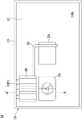
图1是根据本实用新型一实施例的笔记型电脑的主机的俯视示意图,示出机壳内的部分电子元件及散热模块。1 is a schematic top view of a host of a notebook computer according to an embodiment of the present invention, showing some electronic components and a heat dissipation module in the casing.
图2是沿图1中的线A-A’撷取的散热系统(包括机壳及其中的散热模块)的剖面示意图,其中,风扇的具体结构未被示出(为简明的目的)。Fig. 2 is a schematic cross-sectional view of the heat dissipation system (including the case and the heat dissipation module therein) taken along the line A-A' in Fig. 1, wherein the specific structure of the fan is not shown (for the purpose of simplicity).
图3是图2中的散热系统的气流流向示意图。FIG. 3 is a schematic diagram of the airflow direction of the cooling system in FIG. 2 .
图4是根据本实用新型另一实施例的散热系统的剖面示意图。4 is a schematic cross-sectional view of a heat dissipation system according to another embodiment of the present invention.
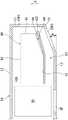
图5是根据本实用新型另一实施例的散热系统的剖面示意图。5 is a schematic cross-sectional view of a heat dissipation system according to another embodiment of the present invention.
【符号说明】【Symbol Description】
10:机壳10: Chassis
10S:内部空间10S: Interior Space
11:底壁11: Bottom wall
12:顶壁12: Top Wall
13:侧壁13: Sidewall
14:倾斜侧壁14: Sloping side walls
20:中央处理器20: CPU
30:热管30: Heat pipe
40:散热鳍片(阵列)40: cooling fins (array)
41:底表面41: Bottom surface
42:顶表面42: Top surface
43:侧表面43: Side Surface
44:倾斜表面44: Sloping Surfaces
50:风扇50: Fan
60:导流板60: deflector
M:主机M: host
T:桌面T: desktop
Z:垂直方向Z: vertical direction
F1:第一(散热)气流F1: First (cooling) airflow
F2:第二(散热)气流F2: Second (cooling) airflow
F3:回流气流F3: Return airflow
G1,G2:间隙G1, G2: Gap
IP:入风口IP: air inlet
OP1:第一出风口OP1: The first air outlet
OP2:第二出风口OP2: Second air outlet
θ:角度θ: angle
【具体实施方式】【Detailed ways】
为使本实用新型的上述和其他目的、特征、和优点能更明显易懂,下文特举较佳实施例并配合所附图式做详细说明。In order to make the above and other objects, features, and advantages of the present invention more clearly understood, preferred embodiments are hereinafter described in detail with the accompanying drawings.
在以下说明中,所称的方位“上”、“下”或类似的用语,仅是用来表示图中所示部分或部件的相对位置关系,并非用来限制本实用新型。当述及一第一元件位于一第二元件上时,可能包括第一元件与第二元件直接接触或间隔有一或更多其他元件的情形。In the following description, the orientations referred to as "upper", "lower" or similar terms are only used to indicate the relative positional relationship of the parts or components shown in the figures, and are not used to limit the present invention. When referring to a first element on a second element, it may include the case where the first element and the second element are in direct contact with or spaced apart by one or more other elements.
在不同的实施例附图中,相似或相同的部分或部件可能使用相同的符号,此是为了简化的目的,并非用以限定所讨论的各个实施例及/或结构之间有特定的关系。In the drawings of different embodiments, the same symbols may be used for similar or identical parts or components, which are for the purpose of simplicity and are not used to limit the specific relationship between the various embodiments and/or structures discussed.
另须强调的是,根据本产业的一般作业,图式中各个特征未必按照比例绘制。事实上,可能任意放大或缩小各个特征的尺寸,以简化或者方便标示。在图式中未绘示或描述的元件,为所属技术领域中具有通常知识者所知的形式。It is also emphasized that, in accordance with common practice in the industry, the various features in the drawings are not necessarily drawn to scale. In fact, the dimensions of the various features may be arbitrarily enlarged or reduced to simplify or facilitate representation. Elements not shown or described in the drawings have forms known to those of ordinary skill in the art.
本实用新型提供一种改良的笔记型电脑散热系统。所述散热系统是应用于一笔记型电脑的主机中。请参阅图1,根据本实用新型一实施例的主机M主要包括一机壳10、一中央处理器 20、一热管30、一散热鳍片阵列40(也可简称作散热鳍片40)以及一风扇50。应了解的是,图1中仅示出主机M的部分部件(为简明的目的),一些额外的部件或特征也可添加到主机M中(例如,在主机M的上还可设置有一键盘),及/或下面所描述的一些特征可在其他实施例中被替换或变更。The utility model provides an improved cooling system for notebook computers. The cooling system is applied to a host of a notebook computer. Referring to FIG. 1, the host M according to an embodiment of the present invention mainly includes a
请参阅图1及图2,在一实施例中,机壳10包括一底壁11、一顶壁12、一侧壁13以及一倾斜侧壁14(请注意,顶壁12和倾斜侧壁14存在但未示于图1中)。顶壁12与底壁11 基本上平行设置,并分别位于机壳10的上、下两面。在操作笔记型电脑时,底壁11是朝向桌面T(如图3所示),而顶壁12是朝向上方(即,使用者的方向)。侧壁13位于底壁11与顶壁12 之间,并与底壁11(和顶壁12)基本上垂直。倾斜侧壁14位于底壁11与侧壁13之间,并与底壁11基本上夹一不等于0度的角度θ,其中,角度θ可介于约15度至约60度之间的范围内,但不限于此,可视实际设计需求作变更。侧壁13和倾斜侧壁14分别沿着顶壁12和底壁11的周边设置,使底壁11、顶壁12、侧壁13与倾斜侧壁14可彼此邻接而形成机壳10的一内部空间10S。中央处理器20、热管30、散热鳍片40以及风扇50均收容在内部空间10S中。Please refer to FIGS. 1 and 2 , in one embodiment, the
另外,底壁11具有一入风口IP,侧壁13具有一第一出风口OP1,且倾斜侧壁14具有一第二出风口OP2。通常,第一出风口OP1及第二出风口OP2分别较佳的为一栅状开口(即,沿着机壳10周边布置的一排开口),以便于用于散热的空气气流流出机壳10。在本实施例中,第一出风口OP1与第二出风口OP2 彼此靠近,且邻近机壳10之后侧(例如,图1所示的上侧)的一角落,但本揭露不以此为限。在本实施例中,第二出风口OP2介于入风口IP与第一出风口OP1之间。更具体而言,在垂直方向(例如,图2中所示的垂直方向Z,其基本上垂直于底壁11及顶壁 12,并与侧壁13平行)上,第二出风口OP2可低于第一出风口OP1 并高于入风口IP。In addition, the
如图1所示,热管30设置于中央处理器20与散热鳍片40之间,且热管30的两端分别与中央处理器20及散热鳍片 40接触。因此,中央处理器20所产生的热量可通过热管30传导至散热鳍片40上。在一些其他实施例中,热管30也可连接其他会产生热量的电子元件(未示出)与散热鳍片40,以帮助导热。如图2所示,散热鳍片40邻近第一出风口OP1和第二出风口OP2 设置。另外,风扇50邻近且对应底壁11上的入风口IP设置。在本实施例中,风扇50为一离心型风扇,其具体的结构和运作机制均为本领域中具有通常知识者所熟知,故在此不多作赘述。As shown in FIG. 1 , the
当笔记型电脑的主机M运作时,位于机壳10内的中央处理器20等电子元件(热源)会产生热量,此时,热管30可将热量自热源传导至散热鳍片40,然后经由风扇50的运转,将空气沿着风扇50的轴向(平行于垂直方向Z)通过底壁11上的入风口IP吸入机壳10(和风扇50的壳体)中,接着产生一空气气流(以下简称气流)自风扇50的一侧边横向地吹向散热鳍片40(如图1 中的箭头所示)并与散热鳍片40发生热交换,最后再通过第一、第二出风口OP1及OP2排出至机壳30外部,以排除废热。When the host M of the notebook computer operates, the electronic components (heat sources) such as the
然而,如前所述,因第二出风口OP2及入风口IP均朝向桌面T(参见图3)设置,故自第二出风口OP2排出的(散热) 气流容易被邻近的入风口IP的进气风压所牵引而导致热风回流,进而影响到散热系统的散热效率。同时,此热风回流现象也会造成机壳10表面的温度升高,导致消费者的使用感受不佳。However, as mentioned above, since the second air outlet OP2 and the air inlet IP are both disposed toward the desktop T (see FIG. 3 ), the (heat dissipation) air flow discharged from the second air outlet OP2 is easily absorbed by the adjacent air inlet IP. The hot air is drawn back by the air pressure, which in turn affects the heat dissipation efficiency of the heat dissipation system. At the same time, the hot air reflow phenomenon will also cause the temperature of the surface of the
为解决上述问题,根据本实用新型实施例的笔记型电脑散热系统进一步包括一高热阻抗的导流板60(参见图2),设置于散热鳍片40与机壳10的底壁11之间的间隙G1中。在一些实施例中,导流板60的热阻抗(或导热系数)范围介于约0.2 W/(m·K)至约1.0W/(m·K)之间,但本揭露不以此为限,也可以选用其他的热阻抗范围。导流板60可由一隔热材料(或称作绝热材料)形成,例如塑胶、陶瓷、石棉等或其他可承受来自风扇50 的热风的隔热材料。在本实施例中,导流板60为一薄型导流片,其厚度(例如,在垂直方向Z上的厚度)小于散热鳍片40的厚度,例如介于约0.15mm至约0.3mm之间,但本揭露不以此为限,也可以选用其他的厚度范围。In order to solve the above problems, the cooling system of the notebook computer according to the embodiment of the present invention further includes a high thermal resistance deflector 60 (see FIG. 2 ), which is disposed between the cooling
通过设置高热阻抗的导流板60,可将来自风扇50的气流基本上分成会流过散热鳍片40的气流以及不流过散热鳍片 40的气流,从而使后续从第二出风口OP2吹出的第二(散热)气流 F2(对应未流过散热鳍片40的气流)的温度可低于从第一出风口 OP1吹出的第一(散热)气流F1(对应流过散热鳍片40的气流)的温度,如图3所示(在图3中,较高温的气流以实心箭头表示,而较低温的气流以空心箭头表示)。By setting the
由于从第二出风口OP2吹出的第二气流F2的温度降低(相较于未设置导流板60的情况),因此可改善热风回流的影响。更具体而言,由于从第二出风口OP2吹出的第二气流F2的温度变低(或是说变成冷风气流),因此受到入风口IP的进气风压牵引的回流气流F3(其流动于机壳10的底壁11与桌面T之间) 的温度也变低,从而避免自入风口IP吸入的气流的温度受到高温的回流气流F3影响而升高(即,避免影响散热效率)以及避免机壳10(底壁11)表面的温度受到高温的回流气流F3影响(例如,热传导)而升高。Since the temperature of the second air flow F2 blown out from the second air outlet OP2 is lowered (compared to the case where the
另一方面,通过导流板60将来自风扇50的气流分层 (即,分为热风气流层及冷风气流层),也可有助于提高散热鳍片 40与底壁11之间的间隙G1中的空气的热传阻抗,从而避免底壁 11表面的温度容易随着邻近的散热鳍片40的温度升高而升高。高温的第一气流F1也可以最有效率的方式自第一出风口OP1(基本上垂直于第一气流F1的方向)排出系统。On the other hand, the air flow from the
经申请人实验后发现,相较于未设置导流板60的情况,提供高热阻抗的导流板60于间隙G1中可使从第二出风口OP2 吹出的第二气流F2的温度降低约4.6℃,同时使整体机壳10的表面温度也降低约4.5℃,因此可改善消费者的使用感受度。After experiments by the applicant, it is found that, compared with the case where the
下面将进一步描述在一些实施例中的导流板60的不同布置形式。Different arrangements of the
先回到图2的实施例,其中,散热鳍片40在剖面图中具有与机壳10匹配的形状。例如,散热鳍片40具有与机壳10 的底壁11平行的一底表面41、与机壳10的顶壁12平行的一顶表面42、与机壳10的侧壁13平行的一侧表面43、以及与机壳 10的倾斜侧壁14平行且介于底表面41与侧表面43之间的一倾斜表面44。在此情况下,导流板60可贴附于散热鳍片40的底表面41上,例如通过一粘着剂或其他适用的接合元件(未示出)。此外,导流板60可进一步沿着散热鳍片40的倾斜表面44延伸。在本实施例中,导流板60与倾斜表面44之间保留有一间隙 G2(即,两者不直接接触)。这可避免导流板60干涉侧壁13上的第一出风口OP1,从而使第一气流F1顺利地自第一出风口OP1排出系统(如图3所示)。在本实施例中,当从散热鳍片40的底部观察时,导流板60基本上完全遮蔽底表面41及倾斜表面44(例如,导流板60具有对应底表面41及倾斜表面44的形状和尺寸)。Returning to the embodiment of FIG. 2 first, the
接着请参阅图4。图4的实施例的大部分特征均与图 2的实施例相同,故在此仅描述差异的部分。在图4中,侧壁13 上的第一出风口OP1的位置稍微向上(沿垂直方向Z)偏移,与图 2中的侧壁13上的第一出风口OP1相比。在此情况下,导流板 60除了贴附于散热鳍片40的底表面41上之外,亦可进一步沿着散热鳍片40的倾斜表面44延伸,并贴附于倾斜表面44上(即,与倾斜表面44直接接触)。在本实施例中,由于第一出风口OP1 的位置向上偏移,故导流板60贴附于倾斜表面44上的部分并不会干涉第一出风口OP1,使第一气流F1仍可顺利地自第一出风口 OP1排出系统。导流板60可通过例如一粘着剂或其他适用的接合元件(未示出)贴附于散热鳍片40的底表面41及倾斜表面44上。在本实施例中,当从散热鳍片40的底部观察时,导流板60基本上完全遮蔽底表面41及倾斜表面44(例如,导流板60具有对应底表面41及倾斜表面44的形状和尺寸)。Please refer to Figure 4 next. Most of the features of the embodiment of FIG. 4 are the same as those of the embodiment of FIG. 2, so only the differences are described here. In Fig. 4, the position of the first air outlet OP1 on the
接着请参阅图5。图5的实施例的大部分特征均与图 2的实施例相同,故在此仅描述差异的部分。在图5中,机壳10 的倾斜侧壁14被省略,且机壳10的侧壁13的底缘直接与底壁 11连接,其中,第二出风口OP2改为设置于底壁11上。类似地,散热鳍片40在剖面图中具有与机壳10匹配的形状。例如,散热鳍片40具有与机壳10的底壁11平行的一底表面41、与机壳10 的顶壁12平行的一顶表面42、以及与机壳10的侧壁13平行的一侧表面43。在此情况下,导流板60可贴附于散热鳍片40的底表面41上,例如通过一粘着剂或其他适用的接合元件(未示出)。此外,导流板60可沿着散热鳍片40的底表面41延伸到第二出风口OP2上方。在本实施例中,当从散热鳍片40的底部观察时,导流板60基本上完全遮蔽底表面41(例如,导流板60具有对应底表面41的形状和尺寸)。Please refer to Figure 5 next. Most of the features of the embodiment of FIG. 5 are the same as those of the embodiment of FIG. 2, so only the differences are described here. In Fig. 5, the
通过上述图2至4中所揭示的布置形式,导流板60 可将散热鳍片40与第二出风口OP2物理隔开,使从第二出风口 OP2流出的第二气流F2基本上不流过散热鳍片40。因此,不与散热鳍片40发生热交换的第二气流F2的温度可低于从第一出风口OP1流出的第一气流F1的温度。2 to 4, the
应理解的是,本文中所述的导流板60的几何形状、构造、布置及制造方法等仅是出于说明的目的,并无意图且也不应被解读为限制本揭露。一旦由本揭露所提示,许多替代方案和修改对于本领域技术人员来说将是显而易见的。It should be understood that the geometry, configuration, arrangement, manufacturing method, etc. of the
另外,上述导流板60较佳的采用一电绝缘的材料,以避免发生短路的问题。In addition, the above-mentioned
综上所述,本实用新型提供一种改良的笔记型电脑散热系统,包括设置于散热鳍片底部与机壳的底壁之间的一薄型高热阻抗的导流板,可将散热鳍片的热交换区域由原先单一的热风区域划分为热风气流层及冷风气流层,进而使朝向桌面方向排出至机壳外部的散热气流的温度降低。如此一来,可有效消除热风回流效应,并减少热传导至机壳的热量以达到降低机壳表面温度的目的。To sum up, the present invention provides an improved cooling system for notebook computers, comprising a thin high-thermal-impedance guide plate disposed between the bottom of the cooling fins and the bottom wall of the casing, The heat exchange area is divided into a hot air airflow layer and a cold air airflow layer from the original single hot air area, thereby reducing the temperature of the heat dissipation airflow discharged to the outside of the case toward the desktop. In this way, the effect of hot air reflow can be effectively eliminated, and the heat transferred to the casing can be reduced to achieve the purpose of lowering the surface temperature of the casing.
虽然本实用新型已以较佳实施例揭露于上,然其并非用以限定本实用新型,任何熟习此项技艺者,在不脱离本实用新型的精神和范围内,当可作些许的更动与润饰,因此本实用新型的保护范围当视后附的申请专利范围所界定者为准。Although the present invention has been disclosed above with preferred embodiments, it is not intended to limit the present invention. Anyone skilled in the art can make some changes without departing from the spirit and scope of the present invention. Therefore, the protection scope of the present invention should be determined by the scope of the appended patent application.
Claims (10)
Priority Applications (1)
| Application Number | Priority Date | Filing Date | Title |
|---|---|---|---|
| CN202220106629.4UCN216979669U (en) | 2022-01-13 | 2022-01-13 | Laptop cooling system |
Applications Claiming Priority (1)
| Application Number | Priority Date | Filing Date | Title |
|---|---|---|---|
| CN202220106629.4UCN216979669U (en) | 2022-01-13 | 2022-01-13 | Laptop cooling system |
Publications (1)
| Publication Number | Publication Date |
|---|---|
| CN216979669Utrue CN216979669U (en) | 2022-07-15 |
Family
ID=82352576
Family Applications (1)
| Application Number | Title | Priority Date | Filing Date |
|---|---|---|---|
| CN202220106629.4UActiveCN216979669U (en) | 2022-01-13 | 2022-01-13 | Laptop cooling system |
Country Status (1)
| Country | Link |
|---|---|
| CN (1) | CN216979669U (en) |
- 2022
- 2022-01-13CNCN202220106629.4Upatent/CN216979669U/enactiveActive
Similar Documents
| Publication | Publication Date | Title |
|---|---|---|
| CN102548358B (en) | electronic device | |
| CN102996516B (en) | Electronic device and its cooling module and its centrifugal fan | |
| CN1666164A (en) | Method and apparatus for cooling circuit components | |
| CN103327787A (en) | Electronic device | |
| CN107643814A (en) | A kind of server radiating air ducting | |
| CN101123863A (en) | Wind scooper | |
| US8356656B2 (en) | Heat dissipation device and method | |
| JP2024002802A (en) | Cooling module and electronic equipment | |
| CN216979669U (en) | Laptop cooling system | |
| US20110042043A1 (en) | Heat dissipation module | |
| CN211349137U (en) | Notebook computer | |
| US7558065B2 (en) | Air guide with heat pipe and heat sink and electronic apparatus equipped with the same | |
| CN104105379B (en) | Heat radiation assembly and display card module | |
| TWM629379U (en) | Heat dissipation system for notebook computer | |
| CN1266567C (en) | computer device | |
| CN101312635A (en) | Air guide cover with heat pipe and radiating fin and electronic device provided with air guide cover | |
| CN2491883Y (en) | heat sink | |
| CN101424964A (en) | Casing structure of electronic device | |
| JP3805723B2 (en) | Electronic device cooling system | |
| TWI832283B (en) | Heat dissipation structure | |
| US20250081386A1 (en) | Fan assembly and electronic device | |
| TWI884009B (en) | Heat dissipation structure for an electronic device | |
| CN2621342Y (en) | Integrated Cooling Module | |
| CN217484805U (en) | Cabinet | |
| CN219754832U (en) | Centrifugal fan module |
Legal Events
| Date | Code | Title | Description |
|---|---|---|---|
| GR01 | Patent grant | ||
| GR01 | Patent grant |