CN216959833U - Startup and shutdown circuit and electronic atomization device - Google Patents
Startup and shutdown circuit and electronic atomization deviceDownload PDFInfo
- Publication number
- CN216959833U CN216959833UCN202122873157.3UCN202122873157UCN216959833UCN 216959833 UCN216959833 UCN 216959833UCN 202122873157 UCN202122873157 UCN 202122873157UCN 216959833 UCN216959833 UCN 216959833U
- Authority
- CN
- China
- Prior art keywords
- switching element
- sensor
- capacitor
- diode
- control signal
- Prior art date
- Legal status (The legal status is an assumption and is not a legal conclusion. Google has not performed a legal analysis and makes no representation as to the accuracy of the status listed.)
- Active
Links
- 238000000889atomisationMethods0.000titleclaimsabstractdescription8
- 239000003990capacitorSubstances0.000claimsabstractdescription52
- 238000001514detection methodMethods0.000claimsdescription7
- 230000001960triggered effectEffects0.000claimsdescription2
- 238000010586diagramMethods0.000description15
- 238000000034methodMethods0.000description3
- 239000000758substrateSubstances0.000description3
- 230000000052comparative effectEffects0.000description2
- 238000002955isolationMethods0.000description2
- 230000009286beneficial effectEffects0.000description1
- 230000009466transformationEffects0.000description1
Images


Classifications
- G—PHYSICS
- G05—CONTROLLING; REGULATING
- G05F—SYSTEMS FOR REGULATING ELECTRIC OR MAGNETIC VARIABLES
- G05F1/00—Automatic systems in which deviations of an electric quantity from one or more predetermined values are detected at the output of the system and fed back to a device within the system to restore the detected quantity to its predetermined value or values, i.e. retroactive systems
- G05F1/10—Regulating voltage or current
- G05F1/46—Regulating voltage or current wherein the variable actually regulated by the final control device is DC
- G05F1/56—Regulating voltage or current wherein the variable actually regulated by the final control device is DC using semiconductor devices in series with the load as final control devices
- G05F1/59—Regulating voltage or current wherein the variable actually regulated by the final control device is DC using semiconductor devices in series with the load as final control devices including plural semiconductor devices as final control devices for a single load
- A—HUMAN NECESSITIES
- A24—TOBACCO; CIGARS; CIGARETTES; SIMULATED SMOKING DEVICES; SMOKERS' REQUISITES
- A24F—SMOKERS' REQUISITES; MATCH BOXES; SIMULATED SMOKING DEVICES
- A24F40/00—Electrically operated smoking devices; Component parts thereof; Manufacture thereof; Maintenance or testing thereof; Charging means specially adapted therefor
- A24F40/50—Control or monitoring
- A24F40/51—Arrangement of sensors
- G—PHYSICS
- G05—CONTROLLING; REGULATING
- G05F—SYSTEMS FOR REGULATING ELECTRIC OR MAGNETIC VARIABLES
- G05F1/00—Automatic systems in which deviations of an electric quantity from one or more predetermined values are detected at the output of the system and fed back to a device within the system to restore the detected quantity to its predetermined value or values, i.e. retroactive systems
- G05F1/10—Regulating voltage or current
- G05F1/46—Regulating voltage or current wherein the variable actually regulated by the final control device is DC
- G05F1/56—Regulating voltage or current wherein the variable actually regulated by the final control device is DC using semiconductor devices in series with the load as final control devices
- G05F1/565—Regulating voltage or current wherein the variable actually regulated by the final control device is DC using semiconductor devices in series with the load as final control devices sensing a condition of the system or its load in addition to means responsive to deviations in the output of the system, e.g. current, voltage, power factor
- G—PHYSICS
- G05—CONTROLLING; REGULATING
- G05F—SYSTEMS FOR REGULATING ELECTRIC OR MAGNETIC VARIABLES
- G05F1/00—Automatic systems in which deviations of an electric quantity from one or more predetermined values are detected at the output of the system and fed back to a device within the system to restore the detected quantity to its predetermined value or values, i.e. retroactive systems
- G05F1/10—Regulating voltage or current
- G05F1/46—Regulating voltage or current wherein the variable actually regulated by the final control device is DC
- G05F1/56—Regulating voltage or current wherein the variable actually regulated by the final control device is DC using semiconductor devices in series with the load as final control devices
- G05F1/575—Regulating voltage or current wherein the variable actually regulated by the final control device is DC using semiconductor devices in series with the load as final control devices characterised by the feedback circuit
- H—ELECTRICITY
- H03—ELECTRONIC CIRCUITRY
- H03K—PULSE TECHNIQUE
- H03K17/00—Electronic switching or gating, i.e. not by contact-making and –breaking
- H03K17/94—Electronic switching or gating, i.e. not by contact-making and –breaking characterised by the way in which the control signals are generated
- H03K17/965—Switches controlled by moving an element forming part of the switch
- H03K17/97—Switches controlled by moving an element forming part of the switch using a magnetic movable element
- A—HUMAN NECESSITIES
- A24—TOBACCO; CIGARS; CIGARETTES; SIMULATED SMOKING DEVICES; SMOKERS' REQUISITES
- A24F—SMOKERS' REQUISITES; MATCH BOXES; SIMULATED SMOKING DEVICES
- A24F40/00—Electrically operated smoking devices; Component parts thereof; Manufacture thereof; Maintenance or testing thereof; Charging means specially adapted therefor
- A24F40/50—Control or monitoring
- H—ELECTRICITY
- H03—ELECTRONIC CIRCUITRY
- H03K—PULSE TECHNIQUE
- H03K2217/00—Indexing scheme related to electronic switching or gating, i.e. not by contact-making or -breaking covered by H03K17/00
- H03K2217/94—Indexing scheme related to electronic switching or gating, i.e. not by contact-making or -breaking covered by H03K17/00 characterised by the way in which the control signal is generated
- H03K2217/94042—Means for reducing energy consumption
- H—ELECTRICITY
- H03—ELECTRONIC CIRCUITRY
- H03K—PULSE TECHNIQUE
- H03K2217/00—Indexing scheme related to electronic switching or gating, i.e. not by contact-making or -breaking covered by H03K17/00
- H03K2217/94—Indexing scheme related to electronic switching or gating, i.e. not by contact-making or -breaking covered by H03K17/00 characterised by the way in which the control signal is generated
- H03K2217/96—Touch switches
- H03K2217/96058—Fail-safe touch switches, where switching takes place only after repeated touch
- H—ELECTRICITY
- H05—ELECTRIC TECHNIQUES NOT OTHERWISE PROVIDED FOR
- H05B—ELECTRIC HEATING; ELECTRIC LIGHT SOURCES NOT OTHERWISE PROVIDED FOR; CIRCUIT ARRANGEMENTS FOR ELECTRIC LIGHT SOURCES, IN GENERAL
- H05B1/00—Details of electric heating devices
- H05B1/02—Automatic switching arrangements specially adapted to apparatus ; Control of heating devices
- H05B1/0202—Switches
- Y—GENERAL TAGGING OF NEW TECHNOLOGICAL DEVELOPMENTS; GENERAL TAGGING OF CROSS-SECTIONAL TECHNOLOGIES SPANNING OVER SEVERAL SECTIONS OF THE IPC; TECHNICAL SUBJECTS COVERED BY FORMER USPC CROSS-REFERENCE ART COLLECTIONS [XRACs] AND DIGESTS
- Y02—TECHNOLOGIES OR APPLICATIONS FOR MITIGATION OR ADAPTATION AGAINST CLIMATE CHANGE
- Y02D—CLIMATE CHANGE MITIGATION TECHNOLOGIES IN INFORMATION AND COMMUNICATION TECHNOLOGIES [ICT], I.E. INFORMATION AND COMMUNICATION TECHNOLOGIES AIMING AT THE REDUCTION OF THEIR OWN ENERGY USE
- Y02D10/00—Energy efficient computing, e.g. low power processors, power management or thermal management
Landscapes
- Engineering & Computer Science (AREA)
- Physics & Mathematics (AREA)
- Electromagnetism (AREA)
- General Physics & Mathematics (AREA)
- Radar, Positioning & Navigation (AREA)
- Automation & Control Theory (AREA)
- Electronic Switches (AREA)
- Dc-Dc Converters (AREA)
Abstract
Description
Translated fromChinese技术领域technical field
本申请涉及开关电路领域,特别是涉及一种开关机电路以及电子雾化装置。The present application relates to the field of switch circuits, in particular to a switch circuit and an electronic atomization device.
背景技术Background technique
电池供电产品通常设置有开关机电路,以在闲置期间关机以降低功耗,同时提高电池续航时间。Battery-powered products are often provided with on-off circuits to shut down during idle periods to reduce power consumption while increasing battery life.
市场上流行一种使用传感器作为启动元件的开关机电路,在用户执行开机操作时,通过传感器输出开机信号使电路导通,以达到开机的目的。A switch circuit that uses a sensor as a starting element is popular in the market. When the user performs a power-on operation, the sensor outputs a power-on signal to make the circuit conduct, so as to achieve the purpose of power-on.
然而,当传感器由于某些原因未复位,后续执行关机操作时,传感器持续输出开机信号,使得开关机电路无法断开,电路持续供电,待机电流大,降低电池的使用时间。However, when the sensor is not reset for some reason, and the subsequent shutdown operation is performed, the sensor continues to output the power-on signal, so that the switch-on circuit cannot be disconnected, the circuit continues to supply power, the standby current is large, and the battery life is reduced.
实用新型内容Utility model content
本申请提供一种开关机电路,能够在传感器未复位时,避免开关机电路持续导通而无法关机。The present application provides a switch circuit, which can prevent the switch circuit from being continuously turned on and unable to shut down when the sensor is not reset.
为解决上述技术问题,本申请提供的第一个技术方案为:提供一种开关机电路,包括:传感器、第一开关元件以及电容,所述传感器基于用户操作生成相应的第一控制信号;所述第一开关元件的第一端与电压输入端连接,所述第一开关元件的第二端与电压输出端连接,其中,所述电压输入端连接电源电压;所述电容,连接在所述第一开关元件的第三端和所述传感器之间,基于所述第一控制信号控制所述第一开关元件是否导通。In order to solve the above technical problems, the first technical solution provided by the present application is to provide a switch circuit, including: a sensor, a first switch element and a capacitor, the sensor generates a corresponding first control signal based on user operations; The first end of the first switch element is connected to the voltage input end, the second end of the first switch element is connected to the voltage output end, wherein the voltage input end is connected to the power supply voltage; the capacitor is connected to the voltage output end. Between the third end of the first switching element and the sensor, whether the first switching element is turned on is controlled based on the first control signal.
其中,所述传感器基于用户开机操作被触发时,所述第一控制信号切换至逻辑低电平;所述传感器复位时,所述第一控制信号切换至逻辑高电平。Wherein, when the sensor is triggered based on a user's power-on operation, the first control signal is switched to a logic low level; when the sensor is reset, the first control signal is switched to a logic high level.
其中,还包括控制芯片,所述控制芯片包括信号输出端口,所述信号输出端口与所述第一开关元件的第三端连接,用于发出第二控制信号以控制所述第一开关元件是否导通。Wherein, it also includes a control chip, the control chip includes a signal output port, the signal output port is connected to the third end of the first switch element, and is used to send a second control signal to control whether the first switch element is on.
其中,还包括控制芯片和第二开关元件,所述控制芯片包括信号输出端口,所述第二开关元件的第一端与地电压连接,所述第二开关元件的第二端与所述第一开关元件的第三端连接,其中,所述第二开关的第三端与所述信号输出端口连接,以接收所述控制芯片发出的第二控制信号;其中,所述控制芯片发出所述第二控制信号以控制所述第二开关元件的通断。Wherein, it also includes a control chip and a second switch element, the control chip includes a signal output port, the first end of the second switch element is connected to the ground voltage, and the second end of the second switch element is connected to the first end of the second switch element. The third end of a switch element is connected to the third end of the second switch, wherein the third end of the second switch is connected to the signal output port to receive the second control signal sent by the control chip; wherein the control chip sends the The second control signal is used to control the on-off of the second switching element.
其中,还包括第一电阻,所述第一电阻的第一端连接所述电压输入端,所述第一电阻的第二端同时与所述第一开关元件的第三端和所述电容的一端连接。It also includes a first resistor, the first end of the first resistor is connected to the voltage input end, and the second end of the first resistor is connected to the third end of the first switching element and the capacitor at the same time. connected at one end.
其中,还包括:第一二极管,所述第一二极管的负极连接所述电压输入端,所述第一二极管的正极连接所述电容的第一端。The method further includes: a first diode, the cathode of the first diode is connected to the voltage input end, and the anode of the first diode is connected to the first end of the capacitor.
其中,还包括:第二二极管,所述第二二极管的负极连接所述电容的第一端或者所述电容与所述传感器连接的第二端,所述第二二极管的正极连接所述控制芯片的侦测反馈端口,以向所述控制芯片反馈所述第一控制信号的变化情况。Wherein, it also includes: a second diode, the cathode of the second diode is connected to the first end of the capacitor or the second end of the capacitor and the sensor, and the second diode is connected to the sensor. The positive pole is connected to the detection feedback port of the control chip, so as to feed back the change of the first control signal to the control chip.
其中,所述第二二极管的负极连接所述电容的第一端时,所述开关机电路还包括第三二极管,所述第三二极管的正极连接所述第一开关元件的第三端,所述第三二极管的负极连接所述电容的第一端。Wherein, when the cathode of the second diode is connected to the first end of the capacitor, the switching circuit further includes a third diode, and the anode of the third diode is connected to the first switching element The third terminal of the third diode is connected to the first terminal of the capacitor.
其中,所述第一开关元件为PMOS晶体管,所述第二开关元件为NMOS晶体管。Wherein, the first switch element is a PMOS transistor, and the second switch element is an NMOS transistor.
为解决上述技术问题,本申请提供的第二个技术方案为:提供一种电子雾化装置,包括上述任意一项所述的开关机电路。In order to solve the above technical problems, the second technical solution provided by the present application is to provide an electronic atomization device, which includes the switch circuit described in any one of the above.
本申请的有益效果,区别于现有技术的情况,本申请提供的开关机电路以及电子雾化装置,包括传感器、第一开关元件以及电容,其中,传感器基于用户操作生成相应的第一控制信号;第一开关元件的第一端与电压输入端连接,第一开关元件的第二端与电压输出端连接,其中,所述电压输入端连接电源电压;电容连接在第一开关元件的第三端和传感器之间,基于第一控制信号控制第一开关元件是否导通。上述开关机电路,能够在传感器未复位时,避免开关机电路持续导通而无法关机。The beneficial effects of the present application are different from those in the prior art. The switch circuit and the electronic atomization device provided by the present application include a sensor, a first switch element and a capacitor, wherein the sensor generates a corresponding first control signal based on a user operation The first end of the first switch element is connected to the voltage input end, the second end of the first switch element is connected to the voltage output end, wherein the voltage input end is connected to the power supply voltage; the capacitor is connected to the third end of the first switch element Between the terminal and the sensor, whether the first switching element is turned on is controlled based on the first control signal. The above switch circuit can prevent the switch circuit from being continuously turned on and unable to shut down when the sensor is not reset.
附图说明Description of drawings
为了更清楚地说明本申请实施例中的技术方案,下面将对实施例描述中所需要使用的附图作简单地介绍,显而易见地,下面描述中的附图仅仅是本申请的一些实施例,对于本领域普通技术人员来讲,在不付出创造性劳动的前提下,还可以根据这些附图获得其它的附图,其中:In order to illustrate the technical solutions in the embodiments of the present application more clearly, the following briefly introduces the drawings that are used in the description of the embodiments. Obviously, the drawings in the following description are only some embodiments of the present application. For those of ordinary skill in the art, under the premise of no creative work, other drawings can also be obtained from these drawings, wherein:
图1为本申请第一实施例提供的开关机电路的电路图;FIG. 1 is a circuit diagram of a switch circuit provided by a first embodiment of the present application;
图2为本申请提供的霍尔传感器的特性图;2 is a characteristic diagram of the Hall sensor provided by the application;
图3为本申请第二实施例提供的开关机电路的电路图;3 is a circuit diagram of a switch circuit provided by a second embodiment of the present application;
图4为本申请第三实施例提供的开关机电路的电路图;4 is a circuit diagram of a switch circuit provided by a third embodiment of the present application;
图5为本申请对比例提供的第一控制信号、第一开关元件的第三端的电压以及电压输出端输出电压的时序图;5 is a timing diagram of the first control signal, the voltage of the third terminal of the first switching element and the output voltage of the voltage output terminal provided by the comparative example of the present application;
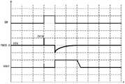
图6为本申请提供的第一控制信号、第一开关元件的第三端的电压以及电压输出端输出电压的时序图;6 is a timing diagram of the first control signal, the voltage of the third terminal of the first switching element, and the output voltage of the voltage output terminal provided by the application;
图7为本申请第四实施例提供的开关机电路的电路图;7 is a circuit diagram of a switch circuit provided by a fourth embodiment of the present application;
图8为本申请一实施例提供的电子雾化装置的结构示意图;8 is a schematic structural diagram of an electronic atomization device provided by an embodiment of the present application;
图9为本申请另一实施例提供的电子雾化装置的结构示意图。FIG. 9 is a schematic structural diagram of an electronic atomization device provided by another embodiment of the present application.
具体实施方式Detailed ways
下面将结合本申请实施例中的附图,对本申请实施例中的技术方案进行清楚、完整地描述,显然,所描述的实施例仅是本申请的一部分实施例,而不是全部的实施例。基于本申请中的实施例,本领域普通技术人员在没有做出创造性劳动前提下所获得的所有其他实施例,都属于本申请保护的范围。The technical solutions in the embodiments of the present application will be clearly and completely described below with reference to the drawings in the embodiments of the present application. Obviously, the described embodiments are only a part of the embodiments of the present application, but not all of the embodiments. Based on the embodiments in the present application, all other embodiments obtained by those of ordinary skill in the art without creative efforts shall fall within the protection scope of the present application.
本申请中的术语“第一”、“第二”、“第三”仅用于描述目的,而不能理解为指示或暗示相对重要性或者隐含指明所指示的技术特征的数量。由此,限定有“第一”、“第二”、“第三”的特征可以明示或者隐含地包括至少一个该特征。The terms "first", "second" and "third" in this application are only used for descriptive purposes, and should not be construed as indicating or implying relative importance or implying the number of indicated technical features. Thus, a feature defined as "first", "second", "third" may expressly or implicitly include at least one of that feature.
在本文中提及“实施例”意味着,结合实施例描述的特定特征、结构或特性可以包含在本申请的至少一个实施例中。在说明书中的各个位置出现该短语并不一定均是指相同的实施例,也不是与其它实施例互斥的独立的或备选的实施例。本领域技术人员显式地和隐式地理解的是,本文所描述的实施例可以与其它实施例相结合。Reference herein to an "embodiment" means that a particular feature, structure, or characteristic described in connection with the embodiment can be included in at least one embodiment of the present application. The appearances of the phrase in various places in the specification are not necessarily all referring to the same embodiment, nor a separate or alternative embodiment that is mutually exclusive of other embodiments. It is explicitly and implicitly understood by those skilled in the art that the embodiments described herein may be combined with other embodiments.
参见图1,为本申请第一实施例提供的开关机电路的电路图,开关机电路1包括电压输入端V1、电压输出端V2、传感器21、第一开关元件Q1、第一电容C1以及第二电容C2。具体的,传感器21的输入侧与电压输入端V1以及第一电容C1的第一端连接,传感器21的接地侧与第一电容C1的第二端以及地电压连接,传感器21的输出侧与第二电容C2的第二端连接,第二电容C2的第一端与第一开关元件Q1的第三端连接,第一开关元件Q1的第一端与电压输入端V1连接,第一开关元件Q1的第二端与电压输出端V2连接。其中,电压输入端V1连接电源电压,用于提供电压VIN,第一开关元件Q1的第三端为控制端,传感器21的输出侧基于用户操作生成相应的第一控制信号SW1,第二电容C2基于第一控制信号SW1控制第一开关元件Q1的通断。Referring to FIG. 1 , which is a circuit diagram of the switch circuit provided by the first embodiment of the application, the
具体的,用户操作传感器21提供第一控制信号SW1通过第二电容C2导通第一开关元件Q1,使电池供电产品开机,电压输入端V1通过第一开关元件Q1和电压输出端V2为负载供电。本实施例中,通过在第一开关元件Q1和传感器21之间设置第二电容C2,将传感器21直接为第一开关元件Q1输出控制信号转化为通过第二电容C2为第一开关元件Q1输出控制信号,实现传感器21与第一开关元件Q1的隔离,使得能够在传感器21未复位时,避免开关机电路1持续导通而无法关机。Specifically, the
在一实施方式中,传感器21为霍尔传感器,用于提供第一控制信号SW1。参见图2,为本申请提供的霍尔传感器的特性图,当用户操作磁性元件靠近霍尔传感器,霍尔传感器所处的磁场强度大于某一值(BOPS)时,霍尔传感器提供逻辑低电平,使第一开关元件Q1导通;当用户操作磁性元件远离霍尔传感器或磁性元件自复位,霍尔传感器所处的磁场强度小于某一值(BRPS)时,霍尔传感器提供逻辑高电平。如果电路中没有设置第二电容C2,当用户操作不当或其他原因导致磁性元件未复位时,霍尔传感器将持续输出逻辑低电平,将导致开关机电路持续供电,待机电流大,同时降低电池使用时间。本实施方式中,通过在第一开关元件Q1和传感器21之间设置第二电容C2,将传感器21直接为第一开关元件Q1输出控制信号转化为通过第二电容C2为第一开关元件Q1输出控制信号,实现传感器21与第一开关元件Q1的隔离,使得能够在传感器21未复位时,在第二电容C2输出逻辑高电平时,实现电路关机。In one embodiment, the
参见图3,为本申请第二实施例提供的开关机电路的电路图,与开关机电路1不同的是,本实施例中的开关机电路2还包括控制芯片22,控制芯片22包括信号输出端口P1,信号输出端口P1与第一开关元件Q1的第三端连接,用于发出第二控制信号SW2以控制第一开关元件Q1的通断。本实施例中,用户操作传感器21提供第一控制信号SW1导通第一开关元件Q1,使电池供电产品开机,即使传感器21复位不在提供第一控制信号SW1,电池供电产品中的控制芯片22的信号输出端口P1可以根据需要通过第二开关元件Q2输出第二控制信号SW2控制第一开关元件Q1持续导通或关断。例如,电池供电产品开机后,控制芯片22上电,控制芯片22根据需要输出逻辑高电平使第一开关元件Q1持续导通,以通过电压输出端V2为负载供电。在供电完成后,控制芯片22也可根据需要输出逻辑低电平使第一开关元件Q1关断。Referring to FIG. 3 , which is a circuit diagram of the switch circuit provided in the second embodiment of the application, different from the
参见图4,为本申请第三实施例提供的开关机电路的电路图,与开关机电路2不同的是,本实施例中的开关机电路3还包括第一电阻R1、第一二极管D1、第二二极管D2、第二开关元件Q2以及控制芯片22的侦测反馈端口P2。其中,电压输入端V1连接第一电阻R1的第一端和第一二极管D1的负极,第二电容C2的第一端连接第一电阻R1的第二端和第一二极管D1的正极。第二开关元件Q2的第一端与地电压连接,第二开关元件Q2的第二端与第一开关元件Q1的第三端连接,其中,第二开关元件Q2的第三端为控制端,第二开关元件Q2的第三端与信号输出端口连接。第一电阻第一电阻第二二极管D2的正极连接控制芯片22的侦测反馈端口P2,第二二极管D2的负极连接在第二电容C2以及传感器21之间。其中,当第一开关元件Q1导通时,电池供电产品开机,电压输入端V1通过第一电阻R1为第二电容C2充电,使得第二电容C2从输入逻辑低电平逐渐转化为输出逻辑高电平,以避免传感器21未复位时第一开关元件Q1的持续导通。且第二开关元件Q2的第三端接收控制芯片22发出的第二控制信号SW2,基于第二控制信号SW2而控制第二开关元件Q2是否导通,从而决定是否通过地电压导通第一开关元件Q1。第二二极管D2连接在第二电容C2以及传感器21之间,以向控制芯片22反馈第一控制信号SW1的变化情况。具体的,本实施例中,在用户未执行开机操作或磁性元件远离霍尔传感器时,传感器21输出逻辑高电平,由于第一电阻R1拉高了第一开关元件Q1的电压,第一开关元件Q1不导通,电路保持关机状态,且第二电容C2两端无电压。当用户执行开机操作或磁性元件靠近霍尔传感器时,传感器21输出逻辑低电平,由于第二电容C2两端的电压不能产生突变,第二电容C2两端都输出低电压,第一开关元件Q1的电压被拉低,第一开关元件Q1导通,电池供电产品开机,控制芯片22上电执行控制程序,在电池供电产品需要保持开机状态时,控制芯片22输出逻辑高电平时,以保持第一开关元件Q1持续导通;在电池供电产品供电结束后或在一定时间阈值内不通过电压输出端V2为负载供电时,控制芯片22输出逻辑低电平时,使第一开关元件Q1断开。Referring to FIG. 4 , which is a circuit diagram of the switch circuit provided by the third embodiment of the application, different from the
本实施例中,通过在传感器21与第一开关元件Q1的通路之间设置第二电容C2,在供电产品开机后,第二电容C2在一定时间内通过电压输入端V1充电完成,使得第一开关元件Q1的第三端恢复高电平,即使用户未有关机操作或磁性元件未复位导致传感器21持续输出逻辑低电平,控制芯片22仍然可以自主控制输出第二控制信号SW2为逻辑低电平使第一开关元件Q1关断,切断电流以使电池供电产品关机。In this embodiment, by setting the second capacitor C2 between the
本实施例中,第一二极管D1的正极连接第二电容C2的第一端,负极连接所述电压输入端V1,以在所述第一控制信号SW1切换至逻辑高电平,辅助对第二电容C2的第一端进行放电。可以理解,在没有第一二极管D1的情况下,在控制芯片22的信号输出端口P1在输出逻辑低电平使电池供电产品自动关机后,第二电容C2将充满电,第一开关元件Q1的第三端恢复为高电平,如果用户此时操作传感器21执行关机操作或使磁性元件复位,传感器21从输出逻辑低电平切换为输出逻辑高电平,由于第二电容C2两端的电压不能突变,第一开关元件Q1的第三端的电压V将瞬间由电压输入端V1输入的电压VIN提高到2VIN,并通过第一电阻R1缓慢放电,若在第一电阻R1缓慢放电过程中,用户又操作电池供电产品开机,传感器21输出逻辑低电平,此时第一开关元件Q1的第三端的电压V(VIN<V<2VIN)跌落一个VIN的电平值,此时的电压可能仍然大于第一开关元件Q1导通的电压,导致第一开关元件Q1无法导通。或在极端的情况下,如传感器21输出逻辑低电平的情况下,控制芯片22自主控制第一开关元件Q1断开,用户操作传感器21关机后又迅速执行开机动作,传感器21由输出逻辑高电平又迅速切换至输出逻辑低电平,第一开关元件Q1的第三端的电压将由2VIN拉低至VIN,导致电池供电产品无法开机。本实施例通过设置第一二极管D1,当用户执行关机操作时,传感器21输出由逻辑低电平切换到逻辑高电平,由于第一二极管D1的存在,辅助对第二电容C2的第一端放电,第一开关元件Q1的第三端的电压将保持在接近VIN值的电压,第一二极管D1在此处有快速放电,钳位电压的作用,第一开关元件Q1仍保持关机状态;当用户关机后又快速执行开机操作,使传感器21输出由逻辑高电平切换到逻辑低电平时,迅速拉低第一开关元件Q1的第三端的电压,实现快速开机。In this embodiment, the anode of the first diode D1 is connected to the first terminal of the second capacitor C2, and the cathode is connected to the voltage input terminal V1, so that when the first control signal SW1 is switched to a logic high level, the auxiliary pair The first end of the second capacitor C2 is discharged. It can be understood that in the absence of the first diode D1, after the signal output port P1 of the
参见图5,为本申请对比例提供的第一控制信号、第一开关元件的第三端的电压以及电压输出端输出电压的时序图;图5为开关机电路3中不设置第一二极管D1,第一开关元件Q1为PMOS管,电池供电产品关机使第一控制信号SW1切换为逻辑高电平时,第一开关元件Q1的栅极的电压瞬间上升至2VIN,并在关机期间通过第一电阻R1缓慢放电,随后在电池供电产品开机使第一控制信号SW1切换为逻辑低电平时,由于第一开关元件Q1的栅极跌落的电压仍然大于第一开关元件Q1导通的电压,导致电池供电产品无法开机,电压输出端V2无电压输出。Referring to FIG. 5, it is a timing chart of the first control signal, the voltage of the third terminal of the first switching element and the output voltage of the voltage output terminal provided for the comparative example of the application; D1, the first switching element Q1 is a PMOS transistor, when the battery-powered product is turned off and the first control signal SW1 is switched to a logic high level, the voltage of the gate of the first switching element Q1 instantly rises to 2VIN, and passes through the first switch during the shutdown period. The resistor R1 is slowly discharged, and then when the battery-powered product is turned on and the first control signal SW1 is switched to a logic low level, the voltage dropped by the gate of the first switching element Q1 is still greater than the voltage at which the first switching element Q1 is turned on, resulting in the battery The power supply product cannot be turned on, and the voltage output terminal V2 has no voltage output.
参见图6,为本申请提供的第一控制信号、第一开关元件的第三端的电压以及电压输出端输出电压的时序图;图6为开关机电路3中设置第一二极管D1,电池供电产品关机使第一控制信号SW1切换为逻辑高电平时,第一开关元件Q1的栅极的电压瞬间上升至2VIN后,由于第一二极管D1辅助放电的作用,第一开关元件Q1的栅极的电压又迅速拉低至VIN,随后在电池供电产品开机使第一控制信号SW1切换为逻辑低电平时,第一开关元件Q1的栅极的电压跌落至小于等于第一开关元件Q1导通的电压,第一开关元件Q1导通,电池供电产品开机,电压输出端V2输出电压为负载供电。其中,第二开关元件Q2为NMOS管,控制芯片22可以在电压输出端V2输出高电平的时间内通过第二开关元件Q2控制信号输出端口P1输出逻辑高电平使第一开关元件Q1持续导通,以保持开机状态;并可根据实际需要,自主控制信号输出端口P1通过第二开关元件Q2输出逻辑低电平使第一开关元件Q1关断,以实现关机。Referring to FIG. 6, the timing diagram of the first control signal, the voltage of the third terminal of the first switching element and the output voltage of the voltage output terminal provided by the application; When the power supply product is turned off and the first control signal SW1 is switched to a logic high level, after the voltage of the gate of the first switching element Q1 rises to 2VIN instantaneously, due to the auxiliary discharge of the first diode D1, the voltage of the first switching element Q1 is reduced. The voltage of the gate is quickly pulled down to VIN, and then when the battery-powered product is turned on and the first control signal SW1 is switched to a logic low level, the voltage of the gate of the first switching element Q1 drops to less than or equal to the conduction of the first switching element Q1. When the voltage is turned on, the first switching element Q1 is turned on, the battery-powered product is turned on, and the output voltage of the voltage output terminal V2 supplies power to the load. The second switching element Q2 is an NMOS transistor, and the
本实施例中,第二二极管D2的负极连接第二电容C2与传感器21连接的第二端,正极连接控制芯片22的侦测反馈端口P2,用于检测传感器21输出的第一控制信号SW1,以向控制芯片22反馈第一控制信号SW1的变化情况。In this embodiment, the cathode of the second diode D2 is connected to the second end of the second capacitor C2 connected to the
参见图7,为本申请第四实施例提供的开关机电路的电路图,与开关机电路3不同的是,本实施例提供的开关机电路4中的第二二极管D2的负极连接第二电容C2的第一端,正极连接控制芯片22的侦测反馈端口P2,第三二极管D3的正极连接第一开关元件Q1的第三端,负极连接第二电容C2的第一端。Referring to FIG. 7 , which is a circuit diagram of the switch circuit provided by the fourth embodiment of the present application, the difference from the
具体的,由于第二二极管D2连接在第二电容C2的第一端,控制芯片22的侦测反馈端口P2输出的信号不再是电平信号,而是脉冲信号,且由于电池供电产品开机后,信号输出端口P1输出的第二控制信号SW2将拉低第一开关元件Q1的第三端的电压,所以需要增加第三二极管D3,以便在电池供电产品关机前可以检测到脉冲信号的变化。Specifically, since the second diode D2 is connected to the first end of the second capacitor C2, the signal output by the detection feedback port P2 of the
参见图8,电子雾化装置包括雾化器10和电池杆20。其中,雾化器10中存储有待雾化基质;电池杆20与雾化器10电连接,为雾化器10供电,以使得雾化器10加热雾化待雾化基质。Referring to FIG. 8 , the electronic atomizer device includes an
在一实施方式中,参见图9,电池杆20包括电芯23和线路板(图未示),电芯23用于存储电能,上述任一实施例提供的开关机电路设置于线路板上,当用户执行开机操作时,第一开关元件Q1导通,电芯23通过线路板为雾化器10提供雾化待雾化基质的电压。In one embodiment, referring to FIG. 9 , the
以上仅为本申请的实施方式,并非因此限制本申请的专利范围,凡是利用本申请说明书及附图内容所作的等效结构或等效流程变换,或直接或间接运用在其他相关的技术领域,均同理包括在本申请的专利保护范围内。The above are only the embodiments of the present application, and are not intended to limit the scope of the patent of the present application. Any equivalent structure or equivalent process transformation made by using the contents of the description and drawings of the present application, or directly or indirectly applied in other related technical fields, All are similarly included in the scope of patent protection of the present application.
Claims (10)
Translated fromChinesePriority Applications (3)
| Application Number | Priority Date | Filing Date | Title |
|---|---|---|---|
| CN202122873157.3UCN216959833U (en) | 2021-11-19 | 2021-11-19 | Startup and shutdown circuit and electronic atomization device |
| US17/987,202US12276996B2 (en) | 2021-11-19 | 2022-11-15 | Power on/off circuit and electronic vaporization device |
| EP22207743.0AEP4184793A3 (en) | 2021-11-19 | 2022-11-16 | Power on/off circuit and electronic vaporization device |
Applications Claiming Priority (1)
| Application Number | Priority Date | Filing Date | Title |
|---|---|---|---|
| CN202122873157.3UCN216959833U (en) | 2021-11-19 | 2021-11-19 | Startup and shutdown circuit and electronic atomization device |
Publications (1)
| Publication Number | Publication Date |
|---|---|
| CN216959833Utrue CN216959833U (en) | 2022-07-12 |
Family
ID=82304223
Family Applications (1)
| Application Number | Title | Priority Date | Filing Date |
|---|---|---|---|
| CN202122873157.3UActiveCN216959833U (en) | 2021-11-19 | 2021-11-19 | Startup and shutdown circuit and electronic atomization device |
Country Status (3)
| Country | Link |
|---|---|
| US (1) | US12276996B2 (en) |
| EP (1) | EP4184793A3 (en) |
| CN (1) | CN216959833U (en) |
Family Cites Families (10)
| Publication number | Priority date | Publication date | Assignee | Title |
|---|---|---|---|---|
| JP2836456B2 (en) | 1993-08-23 | 1998-12-14 | 株式会社デンソー | Optical reader |
| US20050040792A1 (en) | 2003-08-18 | 2005-02-24 | Rajendran Nair | Method & apparatus for charging, discharging and protection of electronic battery cells |
| JP5960611B2 (en) | 2010-02-18 | 2016-08-02 | コーニンクレッカ フィリップス エヌ ヴェKoninklijke Philips N.V. | Reduced power loss power system, electronic device and controller |
| JP5843836B2 (en)* | 2012-11-30 | 2016-01-13 | キヤノン株式会社 | Power supply circuit |
| CN104037720B (en) | 2013-03-05 | 2018-09-07 | 惠州市吉瑞科技有限公司 | The protective device and method that microcontroller supply voltage falls are prevented in electronic cigarette |
| CN107404314A (en)* | 2016-05-20 | 2017-11-28 | 中国科学院苏州纳米技术与纳米仿生研究所 | One key switch circuit and the supply unit with a key switch circuit |
| CN109497615B (en)* | 2018-09-29 | 2021-07-09 | 深圳市合元科技有限公司 | an output control circuit |
| CN112117786B (en)* | 2019-06-20 | 2022-05-31 | Oppo广东移动通信有限公司 | Charging circuit of electronic equipment and electronic equipment |
| WO2021200443A1 (en)* | 2020-03-30 | 2021-10-07 | 三洋電機株式会社 | Electronic circuit unit and battery pack |
| CN114008889B (en)* | 2021-06-18 | 2024-09-20 | 武汉领普科技有限公司 | Power supply circuit, sensor equipment and its application |
- 2021
- 2021-11-19CNCN202122873157.3Upatent/CN216959833U/enactiveActive
- 2022
- 2022-11-15USUS17/987,202patent/US12276996B2/enactiveActive
- 2022-11-16EPEP22207743.0Apatent/EP4184793A3/enactivePending
Also Published As
| Publication number | Publication date |
|---|---|
| US20230161367A1 (en) | 2023-05-25 |
| EP4184793A2 (en) | 2023-05-24 |
| EP4184793A3 (en) | 2023-08-02 |
| US12276996B2 (en) | 2025-04-15 |
Similar Documents
| Publication | Publication Date | Title |
|---|---|---|
| US20240154439A1 (en) | Power supply circuit, sensing device and application thereof | |
| CN103066690B (en) | Low-power consumption standby circuit | |
| CN110693401B (en) | A cleaning robot | |
| EP4268639A1 (en) | Method, apparatus, and system for controlling electronic vaporization device, and electronic vaporization device | |
| CN212725408U (en) | Battery management circuit and power supply circuit | |
| CN217445049U (en) | Power-on protection circuit and electronic equipment | |
| WO2019228052A1 (en) | Low power consumption circuit and electronic device | |
| WO2021138249A1 (en) | Very low power standby circuit such as for a battery management system | |
| WO2021238807A1 (en) | Electronic atomization apparatus | |
| CN216959833U (en) | Startup and shutdown circuit and electronic atomization device | |
| CN108683217B (en) | Power supply voltage monitoring circuit capable of being turned off | |
| CN215185914U (en) | Standby zero-power-consumption circuit applied to battery power supply equipment | |
| CN210924256U (en) | Battery starting circuit | |
| CN114759628A (en) | Power-on protection circuit and electronic equipment | |
| CN203104091U (en) | Low power-consumption standby circuit | |
| CN210111645U (en) | Power supply device capable of realizing rapid discharge | |
| CN209249383U (en) | Voltage-multiplying driving circuit and equipment | |
| CN113206522A (en) | Low standby power consumption power supply circuit and electronic equipment | |
| CN112366763A (en) | Startup and shutdown circuit | |
| CN217406709U (en) | Charging bin, earphone and TWS earphone | |
| CN111669158B (en) | Portable multifunctional switch circuit | |
| CN104935842A (en) | Standby circuit, control method of standby circuit and television system | |
| CN214670476U (en) | Low-power-consumption circuit for MCU and energy storage equipment | |
| CN105116779B (en) | A kind of appliance terminal control panel circuit of low standby power loss | |
| WO2022061516A1 (en) | Control circuit and battery |
Legal Events
| Date | Code | Title | Description |
|---|---|---|---|
| GR01 | Patent grant | ||
| GR01 | Patent grant |