CN216957150U - Safety reminding broadcasting device - Google Patents
Safety reminding broadcasting deviceDownload PDFInfo
- Publication number
- CN216957150U CN216957150UCN202220702623.3UCN202220702623UCN216957150UCN 216957150 UCN216957150 UCN 216957150UCN 202220702623 UCN202220702623 UCN 202220702623UCN 216957150 UCN216957150 UCN 216957150U
- Authority
- CN
- China
- Prior art keywords
- resistor
- water level
- relay
- detection circuit
- signal
- Prior art date
- Legal status (The legal status is an assumption and is not a legal conclusion. Google has not performed a legal analysis and makes no representation as to the accuracy of the status listed.)
- Active
Links
Images
Classifications
- Y—GENERAL TAGGING OF NEW TECHNOLOGICAL DEVELOPMENTS; GENERAL TAGGING OF CROSS-SECTIONAL TECHNOLOGIES SPANNING OVER SEVERAL SECTIONS OF THE IPC; TECHNICAL SUBJECTS COVERED BY FORMER USPC CROSS-REFERENCE ART COLLECTIONS [XRACs] AND DIGESTS
- Y02—TECHNOLOGIES OR APPLICATIONS FOR MITIGATION OR ADAPTATION AGAINST CLIMATE CHANGE
- Y02D—CLIMATE CHANGE MITIGATION TECHNOLOGIES IN INFORMATION AND COMMUNICATION TECHNOLOGIES [ICT], I.E. INFORMATION AND COMMUNICATION TECHNOLOGIES AIMING AT THE REDUCTION OF THEIR OWN ENERGY USE
- Y02D30/00—Reducing energy consumption in communication networks
- Y02D30/70—Reducing energy consumption in communication networks in wireless communication networks
Landscapes
- Measurement Of Levels Of Liquids Or Fluent Solid Materials (AREA)
Abstract
Translated fromChinese
Description
Translated fromChinese技术领域technical field
本实用新型涉及水位安全领域,特别是涉及一种安全提醒播报装置。The utility model relates to the field of water level safety, in particular to a safety reminder broadcasting device.
背景技术Background technique
为防止洪水泛滥成灾,引发灾害事故,我们要进行防汛工作,河道防汛、家用养殖池防汛、一些电力场所如变电站防汛等,现有技术防汛的方案中,通常在需要防汛的地点设置水位监测设备,对监测地的水位进行检测,在监测地的水位超标时进行报警提示,然而受其他因素的影响,如下雨的大小、排水系统的排水状况,水位是实时变化的,在水位超标时进行报警是一种较为粗略的监测方式,还有一些监测方案中,是通过拍摄现场的视频数据,通过复杂的算法分析,得出是否需要防汛的结论,但是这种方案通常需要一整套的防汛监测设备、系统才能实现,价格昂贵,在一些大型的综合监测点才会使用,并不适合家用、民用。In order to prevent floods from causing disasters and accidents, we need to carry out flood control work, such as flood control in rivers, flood control in domestic aquaculture ponds, and flood control in some power places such as substations. The equipment detects the water level of the monitoring site, and gives an alarm when the water level of the monitoring site exceeds the standard. However, affected by other factors, such as the size of the rain and the drainage status of the drainage system, the water level changes in real time, and the water level changes when the water level exceeds the standard. Alarm is a relatively rough monitoring method. In some monitoring schemes, the video data of the scene is captured and the complex algorithm is used to analyze whether flood control is required. However, this scheme usually requires a complete set of flood control monitoring. Only equipment and systems can be realized, and the price is expensive. It is only used in some large-scale comprehensive monitoring points, and is not suitable for household and civilian use.
发明内容SUMMARY OF THE INVENTION
基于此,本申请提供了一种安全提醒播报装置,根据监测地水位的变化情况,给出相应的播报提示,使得防汛监测更为的准确,方式便捷,适用范围广。Based on this, the present application provides a safety reminder broadcasting device, which provides corresponding broadcasting reminders according to changes in the monitored groundwater level, so that flood control monitoring is more accurate, convenient, and applicable.
为了达到上述目的,本申请公开了一种安全提醒播报装置,所述播报装置包括相互连接的水位检测电路、上升检测电路、播报控制电路;所述水位检测电路接收水位信号,将接收的水位信号放大后传输至上升检测电路,在水位信号超标后,输出时间信号传输至播报控制电路,上升检测电路对接收的放大的水位信号进行检测,并输出基准信号到播报控制电路,播报控制电路接收基准信号以及时间信号,计算基准信号与时间信号的差值,输出差值信号到播报模块。In order to achieve the above purpose, the present application discloses a safety reminder broadcast device, the broadcast device includes a water level detection circuit, a rise detection circuit, and a broadcast control circuit connected to each other; the water level detection circuit receives the water level signal, and the received water level signal After amplification, it is transmitted to the rise detection circuit. After the water level signal exceeds the standard, the output time signal is transmitted to the broadcast control circuit. The rise detection circuit detects the received amplified water level signal and outputs the reference signal to the broadcast control circuit. The broadcast control circuit receives the reference Signal and time signal, calculate the difference between the reference signal and the time signal, and output the difference signal to the broadcast module.
本技术的有益效果是:The beneficial effects of this technology are:
本申请在水位超过标准水位时,进行水位上升、水位上升快慢的检测,进行两次检测,在检测到水位一次快速上升后,开启二次检测,在二次检测到水位再次快速上升时,进行播报提醒,及时的提醒人有潜在的洪水危险,提高警惕,做好防汛准备,避免洪水灾害的发生,两次检测,检测的准确度高,且方式便捷,适用范围广,本申请具有自动复位功能,在水位下降,下降至不超过标准水位时,本申请停止向播报模块发送播报信号,不进行语音播报,水位检测电路、上升检测电路、播报控制电路复位,等待下一次的触发播报提醒,本申请根据监测地水位的变化情况,给出相应的播报提示,使得防汛监测更为的准确,方式便捷,适用范围广。In this application, when the water level exceeds the standard water level, the water level rises and the speed of the water level rise is detected, and two detections are performed. After the water level is detected to rise rapidly once, the second detection is started, and when the water level is detected to rise rapidly again, the second detection is performed. Broadcast reminder, timely remind people of potential flood danger, increase vigilance, prepare for flood control, avoid flood disasters, two detections, high detection accuracy, convenient method, wide application range, this application has automatic reset Function, when the water level drops and does not exceed the standard water level, the application stops sending broadcast signals to the broadcast module, does not perform voice broadcast, and resets the water level detection circuit, rise detection circuit, and broadcast control circuit, waiting for the next trigger broadcast reminder, The present application provides corresponding broadcast prompts according to the changes of the monitored ground water level, so that the flood control monitoring is more accurate, the method is convenient, and the scope of application is wide.
附图说明Description of drawings
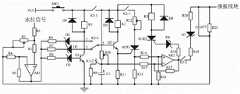
图1为本实用新型的电路原理图。Fig. 1 is the circuit principle diagram of the utility model.
具体实施方式Detailed ways
附图是用来提供对本申请的进一步理解,并且构成说明书一部分,与下面的具体实施方式一起用于解释本申请,但不构成对本申请的限制,以下结合附图对本申请的具体实施方式进行详细说明。The accompanying drawings are used to provide a further understanding of the application, and constitute a part of the specification. Together with the following specific embodiments, they are used to explain the application, but do not constitute a limitation to the application. The specific embodiments of the application are described in detail below with reference to the accompanying drawings. illustrate.
一种安全提醒播报装置,所述播报装置包括相互连接的水位检测电路、上升检测电路、播报控制电路;所述水位检测电路接收水位信号,将接收的水位信号放大后传输至上升检测电路,在水位信号超标后,输出时间信号传输至播报控制电路,上升检测电路对接收的放大的水位信号进行检测,并输出基准信号到播报控制电路,播报控制电路接收基准信号以及时间信号,计算基准信号与时间信号的差值,输出差值信号到播报模块。A safety reminder broadcast device, the broadcast device comprises a water level detection circuit, a rise detection circuit, and a broadcast control circuit that are connected to each other; the water level detection circuit receives a water level signal, amplifies the received water level signal and transmits it to the rise detection circuit, where After the water level signal exceeds the standard, the output time signal is transmitted to the broadcast control circuit, and the rise detection circuit detects the received amplified water level signal, and outputs the reference signal to the broadcast control circuit. The broadcast control circuit receives the reference signal and the time signal, and calculates the reference signal and the time signal. The difference value of the time signal, and output the difference value signal to the broadcast module.
所述水位检测电路包括电阻R1,电阻R1的一端连接水位信号,电阻R1的另一端分别连接电阻R2的一端、可变电阻R3的一端,可变电阻R3的另一端分别连接可变电阻R3的可调端、电阻R4的一端、三极管Q1的发射极、电阻R9的一端、电容C1的正极并连接地,电阻R2的另一端连接运放器AR1的同相输入端,电阻R4的另一端分别连接电阻R5的一端、运放器AR1的反向输入端,运放器AR1的输出端分别连接电阻R5的另一端、电阻R8的一端,电阻R8的另一端连接稳压管D3的负极,稳压管D3的正极连接三极管Q1的基极,三极管Q1的集电极分别连接继电器K1的一端、二极管D4的正极,继电器K1的另一端分别连接二极管D4的负极、按钮开关SW1的一端、继电器K1的常开触点K1-1的一端,按钮开关SW1的另一端连接电源VCC,继电器K1的常开触点K1-1的另一端连接可变电阻R10的一端,可变电阻R10的另一端分别连接可变电阻R10的可调端、电容C1的正极、继电器K1的常闭触点K1-2的一端,继电器K1的常闭触点K1-2的另一端连接电阻R9的另一端;The water level detection circuit includes a resistor R1, one end of the resistor R1 is connected to the water level signal, the other end of the resistor R1 is respectively connected to one end of the resistor R2 and one end of the variable resistor R3, and the other end of the variable resistor R3 is respectively connected to the variable resistor R3. The adjustable end, one end of the resistor R4, the emitter of the transistor Q1, one end of the resistor R9, the positive electrode of the capacitor C1 are connected to the ground, the other end of the resistor R2 is connected to the non-inverting input of the operational amplifier AR1, and the other ends of the resistor R4 are respectively connected One end of the resistor R5, the reverse input end of the op amp AR1, the output end of the op amp AR1 is respectively connected to the other end of the resistor R5, one end of the resistor R8, the other end of the resistor R8 is connected to the negative electrode of the voltage regulator tube D3, the voltage regulator The anode of the tube D3 is connected to the base of the transistor Q1, the collector of the transistor Q1 is respectively connected to one end of the relay K1 and the anode of the diode D4, and the other end of the relay K1 is respectively connected to the cathode of the diode D4, one end of the button switch SW1, and the normal of the relay K1. One end of the open contact K1-1, the other end of the button switch SW1 is connected to the power supply VCC, the other end of the normally open contact K1-1 of the relay K1 is connected to one end of the variable resistor R10, and the other end of the variable resistor R10 is connected to the The adjustable end of the variable resistor R10, the positive electrode of the capacitor C1, one end of the normally closed contact K1-2 of the relay K1, and the other end of the normally closed contact K1-2 of the relay K1 is connected to the other end of the resistor R9;
所述水位检测电路的工作原理为:水位信号进入本申请的水位检测电路中,水位信号可由现有技术的水位传感器检测输出,具体的可选用型号为SIN-ZP的水位传感器,调节可变电阻R3的阻值可以调节水位信号的大小,利用运放器AR1对水位信号进行放大,在水位信号大于稳压管D3的击穿值时,稳压管D3击穿,三极管导通,继电器K1得电,控制继电器K1的常开触点K1-1闭合,继电器K1的常闭触点K1-2断开,按钮开关SW1为总开关,闭合按钮开关SW1,电源VCC对电容C1进行充电,调节可变电阻R10的阻值可以调节电源VCC对电容C1的充电时间,电容C1的正极输出时间信号传输至播报控制电路,运放器AR1的输出端输出放大的水位信号传输至上升检测电路。The working principle of the water level detection circuit is as follows: the water level signal enters the water level detection circuit of the present application, and the water level signal can be detected and output by a water level sensor in the prior art. The resistance value of R3 can adjust the size of the water level signal. The op amp AR1 is used to amplify the water level signal. When the water level signal is greater than the breakdown value of the voltage regulator tube D3, the voltage regulator tube D3 breaks down, the transistor is turned on, and the relay K1 gets Electric, the normally open contact K1-1 of the control relay K1 is closed, the normally closed contact K1-2 of the relay K1 is disconnected, the button switch SW1 is the main switch, close the button switch SW1, the power supply VCC charges the capacitor C1, and the adjustment can be The resistance value of the variable resistor R10 can adjust the charging time of the power supply VCC to the capacitor C1. The positive output time signal of the capacitor C1 is transmitted to the broadcast control circuit, and the output terminal of the operational amplifier AR1 outputs the amplified water level signal and transmits it to the rise detection circuit.
所述上升检测电路包括电阻R7,电阻R7的一端分别连接电阻R6的一端、水位检测电路中的运放器AR1的输出端,电阻R7的另一端连接稳压管D2的负极,稳压管D2的正极连接继电器K3的双掷开关K3-1的端口3,电阻R6的另一端连接稳压管D1的负极,稳压管D1的正极连接继电器K3的双掷开关K3-1的端口1,继电器K3的双掷开关K3-1的端口2连接三极管Q2的基极,三极管Q2的发射极分别连接电阻R11的一端、晶闸管SCR1的控制极,电阻R11的另一端连接电阻R13的另一端并连接地,晶闸管SCR1的阴极连接电阻R13的另一端,三极管Q2的集电极分别连接继电器K2的一端、二极管D5的正极,继电器K2的另一端分别连接二极管D5的负极、继电器K2的常开触点K2-1的一端、水位检测电路中的可变电阻R10的一端,继电器K2的常开触点K2-1的另一端连接可变电阻R12的一端,可变电阻R12的另一端分别连接可变电阻R12的可调端、晶闸管SCR1的阳极;The rise detection circuit includes a resistor R7, one end of the resistor R7 is respectively connected to one end of the resistor R6 and the output end of the operational amplifier AR1 in the water level detection circuit, and the other end of the resistor R7 is connected to the negative electrode of the voltage regulator tube D2, which is the voltage regulator tube D2. The positive pole of the relay K3 is connected to the
所述上升检测电路的工作原理为:上升检测电路接收放大的水位信号,水位上升,水位信号变大使得稳压管D2击穿时,水位信号通过闭合的继电器K3的双掷开关K3-1的端口3和端口2使得三极管Q2的基极得到触发电压,或者水位继续上升,水位信号持续增大使得稳压管D1击穿,水位信号通过闭合的继电器K3的双掷开关K3-1的端口1和端口2使得三极管Q2的基极得到触发电压,三极管Q2的基极得到触发电压后,三极管Q2导通,继电器K2得电,控制继电器K2的常开触点K2-1闭合,晶闸管SCR1导通,晶闸管SCR1的阴极输出基准信号到播报控制电路中;The working principle of the rising detection circuit is as follows: the rising detection circuit receives the amplified water level signal, the water level rises, and the water level signal becomes larger so that when the voltage regulator tube D2 breaks down, the water level signal passes through the double throw switch K3-1 of the closed
稳压管D1的击穿值大于稳压管D2的击穿值,稳压管D2的击穿值大于稳压管D3的击穿值。The breakdown value of the zener tube D1 is greater than that of the zener tube D2, and the breakdown value of the zener tube D2 is greater than that of the zener tube D3.
所述播报控制电路包括电阻R15,电阻R15的一端连接水位检测电路中的电容C1的正极,电阻R15的另一端分别连接电阻R17的一端、运放器AR2的反相输入端,电阻R14的一端连接上升检测电路中的晶闸管SCR1的阴极,电阻R14的另一端分别连接电阻R16的一端、运放器AR2的同相输入端,电阻R16的另一端分别连接晶闸管SCR2的阴极、电容C2的一端、电阻R21的一端并连接地,运放器AR2的输出端分别连接电阻R17的另一端、电阻R18的一端、继电器K3的常开触点K3-2的一端,电阻R18的另一端连接稳压管D6的负极,稳压管D6的正极连接晶闸管SCR2的控制极,晶闸管SCR2的阳极分别连接继电器K3的一端、二极管D8的正极,继电器K3的另一端分别连接二极管D8的负极、水位检测电路中的可变电阻R10的一端,继电器K3的常开触点K3-2的另一端连接电阻R19的一端,电阻R19的另一端连接稳压管D7的负极,稳压管D7的正极连接电阻R20的一端,电阻R20的另一端分别连接电容C2的另一端、电阻R21的另一端、播报模块;The broadcast control circuit includes a resistor R15, one end of the resistor R15 is connected to the positive electrode of the capacitor C1 in the water level detection circuit, the other end of the resistor R15 is connected to one end of the resistor R17, the inverting input end of the operational amplifier AR2, and one end of the resistor R14 Connect the cathode of the thyristor SCR1 in the rising detection circuit, the other end of the resistor R14 is respectively connected to one end of the resistor R16, the non-inverting input end of the op amp AR2, the other end of the resistor R16 is respectively connected to the cathode of the thyristor SCR2, one end of the capacitor C2, and the resistor One end of R21 is connected to the ground, the output end of the operational amplifier AR2 is connected to the other end of the resistor R17, one end of the resistor R18, one end of the normally open contact K3-2 of the relay K3, and the other end of the resistor R18 is connected to the voltage regulator tube D6 The anode of the zener tube D6 is connected to the control pole of the thyristor SCR2, the anode of the thyristor SCR2 is respectively connected to one end of the relay K3 and the anode of the diode D8, and the other end of the relay K3 is respectively connected to the cathode of the diode D8 and the water level detection circuit. One end of the variable resistor R10, the other end of the normally open contact K3-2 of the relay K3 is connected to one end of the resistor R19, the other end of the resistor R19 is connected to the negative electrode of the Zener tube D7, and the positive pole of the Zener tube D7 is connected to one end of the resistor R20, The other end of the resistor R20 is respectively connected to the other end of the capacitor C2, the other end of the resistor R21, and the broadcasting module;
所述播报控制电路的工作原理为:播报控制电路接收水位检测电路输出的时间信号,还接收上升检测电路输出的基准信号,利用运放器AR2、电阻R14、电阻R15、电阻R16、电阻R17组成差分电路,差分电路输出差值信号,当差值信号为高电平时,高电平的差值信号使得稳压管D6击穿时,晶闸管SCR2导通,继电器K3得电,控制继电器K3的常开触点K3-2闭合,当运放器AR2输出的差值信号为高电平且使得稳压管D7击穿时,播报控制电路在电阻R20与电容C2的相连端处输出播报信号到播报模块,播报模块进行语音播报,播报模块可选用现有技术的具有语音播报功能的电路结构,可以是集成的语音芯片,具体的关于播报模块的内容不再详述;The working principle of the broadcast control circuit is as follows: the broadcast control circuit receives the time signal output by the water level detection circuit, and also receives the reference signal output by the rise detection circuit. Differential circuit, the differential circuit outputs the difference signal, when the difference signal is high level, the high level difference signal makes the voltage regulator tube D6 break down, the thyristor SCR2 is turned on, the relay K3 is energized, and the normal control of the relay K3 is controlled. The open contact K3-2 is closed, when the difference signal output by the operational amplifier AR2 is high and the voltage regulator tube D7 is broken down, the broadcast control circuit outputs the broadcast signal at the connecting end of the resistor R20 and the capacitor C2 to the broadcast module, the broadcast module performs voice broadcast, and the broadcast module can be selected from the circuit structure with the function of voice broadcast in the prior art, which can be an integrated voice chip, and the specific content of the broadcast module will not be described in detail;
稳压管D6的击穿值大于稳压管D7的击穿值。The breakdown value of the Zener tube D6 is greater than that of the Zener tube D7.
具体工作过程为:The specific working process is:
闭合总开关SW1,本申请的方案接通电源启动;Close the main switch SW1, and the solution of the present application is powered on to start;
在防汛监测中,如家用养殖池的防汛、变电站的路面积水防汛等等,在监测地的合适位置放置水位监测设备,如水位传感器,具体的可选用型号为SIN-ZP的水位传感器,水位信号进入本申请的水位检测电路中;In flood control monitoring, such as flood control of domestic breeding ponds, flood control of substation road areas, etc., place water level monitoring equipment, such as water level sensors, at appropriate locations in the monitoring site. The specific optional model is SIN-ZP water level sensor, water level The signal enters the water level detection circuit of the present application;
所述水位检测电路中,调节可变电阻R3的阻值可以调节水位信号的大小,运放器AR1对接收的水位信号进行放大,运放器AR1的输出端输出放大的水位信号传输至上升检测电路;In the water level detection circuit, the magnitude of the water level signal can be adjusted by adjusting the resistance value of the variable resistor R3, the operational amplifier AR1 amplifies the received water level signal, and the output terminal of the operational amplifier AR1 outputs the amplified water level signal and transmits it to the rising detection circuit. circuit;
在监测地的水位超过标准1号水位时,设置稳压管D3击穿,三极管Q1导通,继电器K1得电,控制继电器K1的常开触点K1-1闭合,电源VCC对电容C1进行充电,随着充电时间的增加,电容C1上的电压升高,电容C1上的电压的大小也代表了充电时间的长短,调节可变电阻R10的阻值,可以调节电容C1上电压变化的快慢,同时,继电器K1的常闭触点K1-2断开,电阻R9为电容C1的放电电阻,电容C1不进行放电,电容C1的正极输出时间信号到播报控制电路;When the water level of the monitoring ground exceeds the standard No. 1 water level, the voltage regulator tube D3 is set to break down, the transistor Q1 is turned on, the relay K1 is energized, the normally open contact K1-1 of the control relay K1 is closed, and the power supply VCC charges the capacitor C1 , as the charging time increases, the voltage on the capacitor C1 increases, and the voltage on the capacitor C1 also represents the length of the charging time. Adjusting the resistance of the variable resistor R10 can adjust the speed of the voltage change on the capacitor C1. At the same time, the normally closed contact K1-2 of the relay K1 is disconnected, the resistor R9 is the discharge resistor of the capacitor C1, the capacitor C1 does not discharge, and the positive pole of the capacitor C1 outputs a time signal to the broadcast control circuit;
设置2号水位,2号水位值大于标准1号水位值,稳压管D2的击穿值大于稳压管D3的击穿值,所述上升检测电路接收水位检测电路中的运放器AR1输出的放大的水位信号,在监测地的水位继续上升,超过2号水位时,上升检测电路中的稳压管D2击穿,放大的水位信号经过闭合的继电器K3的双掷开关K3-1的端口3和端口2为三极管Q2的基极提供触发电压,三极管Q2导通,继电器K2得电,控制继电器K2的常开触点K2-1闭合,晶闸管SCR1导通,晶闸管SCR1的阴极输出基准信号到播报控制电路中;Set the No. 2 water level, the No. 2 water level value is greater than the standard No. 1 water level value, the breakdown value of the voltage regulator tube D2 is greater than the breakdown value of the voltage regulator tube D3, and the rise detection circuit receives the output of the operational amplifier AR1 in the water level detection circuit When the water level of the monitoring ground continues to rise and exceeds the No. 2 water level, the voltage regulator tube D2 in the rising detection circuit will break down, and the amplified water level signal will pass through the double-throw switch K3-1 port of the closed relay K3. 3 and port 2 provide the trigger voltage for the base of the transistor Q2, the transistor Q2 is turned on, the relay K2 is energized, the normally open contact K2-1 of the control relay K2 is closed, the thyristor SCR1 is turned on, and the cathode of the thyristor SCR1 outputs the reference signal to In the broadcast control circuit;
所述播报控制电路接收上升检测电路输出的基准信号,还接收水位检测电路输出的时间信号,利用运放器AR2、电阻R14、电阻R15、电阻R16、电阻R17组成差分电路,差分电路计算基准信号和时间信号的差值,输出差值信号,差值信号的大小代表由标准1号水位上升到2号水位的快慢,由标准1号水位上升到2号水位的时间短时,水位检测电路输出的时间信号小,差分电路输出高电平的差值信号,高电平的差值信号使得稳压管D6击穿,晶闸管SCR2导通,继电器K3得电,控制上升检测电路中的继电器K3的双掷开关K3-1的端口1和端口2闭合,设置稳压管D1的击穿值大于稳压管D2的击穿值,稳压管D1此时不会击穿,三极管Q2不会导通,上升检测电路输出的基准信号为低电平,播报控制电路中的差分电路输出的差值信号为低电平,低电平的差值信号通过闭合的继电器K3的常开触点K3-2不能使得稳压管D7击穿,播报控制电路不进行播报提醒,至此,水位超过标准1号水位,且水位上升速度快的一次检测结束;The broadcast control circuit receives the reference signal output by the rising detection circuit, and also receives the time signal output by the water level detection circuit, and uses the operational amplifier AR2, the resistor R14, the resistor R15, the resistor R16, and the resistor R17 to form a differential circuit, and the differential circuit calculates the reference signal. The difference between the time signal and the time signal, the difference signal is output. The magnitude of the difference signal represents the speed of rising from the standard No. 1 water level to the No. 2 water level. When the time from the standard No. 1 water level to the No. 2 water level is short, the water level detection circuit outputs When the time signal is small, the differential circuit outputs a high-level differential signal. The high-level differential signal causes the voltage regulator D6 to break down, the thyristor SCR2 is turned on, and the relay K3 is energized, which controls the relay K3 in the rising detection circuit. Port 1 and port 2 of the double-throw switch K3-1 are closed, and the breakdown value of the Zener tube D1 is set to be greater than that of the Zener tube D2. The Zener tube D1 will not break down at this time, and the transistor Q2 will not be turned on. , the reference signal output by the rising detection circuit is low level, the difference signal output by the differential circuit in the broadcast control circuit is low level, and the low level difference signal passes through the normally open contact K3-2 of the closed relay K3 The voltage regulator tube D7 cannot be broken down, and the broadcast control circuit does not broadcast a reminder. At this point, the water level exceeds the standard No. 1 water level, and the water level rises quickly. A detection is over;
为提高检测的准确度,本申请进行二次检测,在一次检测结束后,上升检测电路中的继电器K3的双掷开关K3-1的端口1和端口2是闭合的,在水位持续上升,上升到超过3号水位时,上升检测电路中的稳压管D1击穿,稳压管D1的击穿值大于稳压管D2的击穿值,三极管Q2导通,晶闸管SCR1导通,上升检测电路输出基准信号到播报控制电路中,判定由2号水位快速上升到3号水位时,播报控制电路中的差分电路输出高电平的差值信号,高电平的差值信号使得稳压管D7击穿,经过电阻R20、电容C2的延时作用,目的是提高检测准确度,延时后输出播报信号到播报模块,播报模块进行语音播报,播报模块可选用现有技术的具有语音播报功能的电路结构,可以是集成的语音芯片,具体的关于播报模块的内容不再详述,提醒人此时水位高,且上升速度快,需要提高警惕,防止洪水引发灾害事故,结合实际情况进行防汛工作;In order to improve the detection accuracy, this application performs a secondary detection. After the primary detection is completed, the port 1 and port 2 of the double-throw switch K3-1 of the relay K3 in the rising detection circuit are closed, and the water level continues to rise. When the water level exceeds No. 3, the voltage regulator tube D1 in the rising detection circuit breaks down, the breakdown value of the voltage regulator tube D1 is greater than the breakdown value of the voltage regulator tube D2, the transistor Q2 is turned on, the thyristor SCR1 is turned on, and the rise detection circuit Output the reference signal to the broadcast control circuit, and when it is determined that the water level from No. 2 rises to the water level of No. 3 rapidly, the differential circuit in the broadcast control circuit outputs a high-level difference signal, and the high-level difference signal makes the voltage regulator tube D7 Breakdown, through the delay function of resistor R20 and capacitor C2, the purpose is to improve the detection accuracy. After the delay, the broadcast signal is output to the broadcast module, and the broadcast module performs voice broadcast. The broadcast module can be selected from the existing technology. The circuit structure can be an integrated voice chip. The specific content of the broadcast module will not be described in detail. It reminds people that the water level is high and the rising speed is fast. It is necessary to be vigilant to prevent floods from causing disasters and accidents, and to carry out flood control work according to the actual situation. ;
在水位下降至安全值,降低到标准1号水位线以下时,水位检测电路中的稳压管D3不击穿,三极管Q1不导通,继电器K1不得电,继电器K1的常开触点K1-1断开,播报控制电路不进行语音播报提醒,同时水位检测电路中的继电器K1的常闭触点K1-2闭合,电容C1通过电阻R9进行放电,电容C1复位,至此,本申请的水位检测电路、上升检测电路、播报控制电路复位,等待下一次的检测;When the water level drops to a safe value and falls below the standard No. 1 water level line, the voltage regulator tube D3 in the water level detection circuit will not break down, the transistor Q1 will not be turned on, the relay K1 will not be energized, and the normally open contact K1- of the relay K1 1 is disconnected, the broadcast control circuit does not perform a voice broadcast reminder, and at the same time, the normally closed contact K1-2 of the relay K1 in the water level detection circuit is closed, the capacitor C1 is discharged through the resistor R9, and the capacitor C1 is reset. The circuit, the rise detection circuit, and the broadcast control circuit are reset, waiting for the next detection;
本申请的装置可结合水位监测设备一起使用。The apparatus of the present application may be used in conjunction with water level monitoring equipment.
本技术的有益效果是:The beneficial effects of this technology are:
1.本申请在水位超过标准水位时,进行水位上升、水位上升快慢的检测,进行两次检测,在检测到水位一次快速上升后,开启二次检测,在二次检测到水位再次快速上升时,进行播报提醒,及时的提醒人有潜在的洪水危险,提高警惕,做好防汛准备,避免洪水灾害的发生,两次检测,检测的准确度高,且方式便捷,适用范围广;1. In this application, when the water level exceeds the standard water level, the water level rises and the speed of the water level rise is detected, and two detections are performed. After the water level is detected to rise rapidly once, the second detection is turned on. When the water level is detected to rise rapidly again. , broadcast reminders, timely remind people of potential flood danger, increase vigilance, make flood control preparations, and avoid flood disasters, two detections, the detection accuracy is high, and the method is convenient and widely applicable;
2.本申请具有自动复位功能,在水位下降,下降至不超过标准水位时,稳压管D3不会导通,三极管Q1不会导通,继电器K1失电,控制继电器K1的常闭按钮K1-2闭合,电容C1进行放电,放电完毕后复位,同时继电器K1的常开触点K1-1断开,控制上升检测电路、播报控制电路不与电源VCC接通,至此,本申请停止向播报模块发送播报信号,不进行语音播报,水位检测电路、上升检测电路、播报控制电路复位,等待下一次的触发播报提醒。2. The application has an automatic reset function. When the water level drops and does not exceed the standard water level, the voltage regulator D3 will not be turned on, the transistor Q1 will not be turned on, the relay K1 will lose power, and the normally closed button K1 of the control relay K1 will not be turned on. -2 is closed, the capacitor C1 is discharged, reset after discharge, and the normally open contact K1-1 of the relay K1 is disconnected at the same time, the control rise detection circuit and the broadcast control circuit are not connected to the power supply VCC, so far, the application stops to broadcast The module sends the broadcast signal, does not perform voice broadcast, the water level detection circuit, the rise detection circuit, and the broadcast control circuit are reset, waiting for the next trigger broadcast reminder.
本申请提供的一种安全提醒播报装置,根据监测地水位的变化情况,给出相应的播报提示,使得防汛监测更为的准确,方式便捷,适用范围广。A safety reminder broadcasting device provided by the present application provides corresponding broadcasting reminders according to changes in the monitored ground water level, so that the flood control monitoring is more accurate, the method is convenient, and the scope of application is wide.
Claims (4)
Priority Applications (1)
| Application Number | Priority Date | Filing Date | Title |
|---|---|---|---|
| CN202220702623.3UCN216957150U (en) | 2022-03-29 | 2022-03-29 | Safety reminding broadcasting device |
Applications Claiming Priority (1)
| Application Number | Priority Date | Filing Date | Title |
|---|---|---|---|
| CN202220702623.3UCN216957150U (en) | 2022-03-29 | 2022-03-29 | Safety reminding broadcasting device |
Publications (1)
| Publication Number | Publication Date |
|---|---|
| CN216957150Utrue CN216957150U (en) | 2022-07-12 |
Family
ID=82299413
Family Applications (1)
| Application Number | Title | Priority Date | Filing Date |
|---|---|---|---|
| CN202220702623.3UActiveCN216957150U (en) | 2022-03-29 | 2022-03-29 | Safety reminding broadcasting device |
Country Status (1)
| Country | Link |
|---|---|
| CN (1) | CN216957150U (en) |
- 2022
- 2022-03-29CNCN202220702623.3Upatent/CN216957150U/enactiveActive
Similar Documents
| Publication | Publication Date | Title |
|---|---|---|
| CN205246760U (en) | Photovoltaic module array insulation against ground impedance detection circuitry | |
| CN109274177B (en) | Power distribution area safe electricity use monitoring system and monitoring method | |
| CN101557119B (en) | Charging control circuit of secondary battery | |
| US20110260061A1 (en) | Pyroelectric Motion Detection Circuit | |
| CN216957150U (en) | Safety reminding broadcasting device | |
| CN207517157U (en) | A kind of solar energy the wooded mountain fire protection warning device | |
| CN104852693B (en) | A kind of short-circuit protection circuit for power amplifier output | |
| CN206862447U (en) | A kind of automatic controllable lock system | |
| CN207558142U (en) | A kind of monitoring scenic spot manages system | |
| CN207717912U (en) | Power circuit overheats automatic protective system | |
| CN204681072U (en) | Current foldback circuit | |
| CN208969801U (en) | Fire hazard of storied house automatic alarm system | |
| CN203339676U (en) | Battery reverse short circuit protection circuit | |
| CN216170538U (en) | Water quality safety early warning system for water purifier equipment | |
| CN215813272U (en) | Cable intelligent protection device and cable intelligent detection system | |
| CN108008239B (en) | Detection device for PE line in power supply network, conductive charging system and electric vehicle | |
| CN209000177U (en) | 10KV power distribution station anti-power alarm device | |
| CN204241873U (en) | An intelligent electrical cabinet | |
| CN203503115U (en) | Swimming safety protection system | |
| CN2406193Y (en) | Water-feed turning-on and power cut-off device for electric water heater | |
| CN216817570U (en) | Electricity consumption detection control device | |
| CN223006284U (en) | Leakage alarm device of household photovoltaic grid-connected system | |
| CN206878516U (en) | A kind of temperature alarm | |
| CN206863052U (en) | Urban river water flow rate monitoring system | |
| CN206332472U (en) | UPS electric supply installations |
Legal Events
| Date | Code | Title | Description |
|---|---|---|---|
| GR01 | Patent grant | ||
| GR01 | Patent grant |