CN216945158U - Clamping mechanism, goods taking device and transfer robot - Google Patents
Clamping mechanism, goods taking device and transfer robotDownload PDFInfo
- Publication number
- CN216945158U CN216945158UCN202123317291.1UCN202123317291UCN216945158UCN 216945158 UCN216945158 UCN 216945158UCN 202123317291 UCN202123317291 UCN 202123317291UCN 216945158 UCN216945158 UCN 216945158U
- Authority
- CN
- China
- Prior art keywords
- guide
- plate
- arm
- sliding
- mounting plate
- Prior art date
- Legal status (The legal status is an assumption and is not a legal conclusion. Google has not performed a legal analysis and makes no representation as to the accuracy of the status listed.)
- Active
Links
- 230000007246mechanismEffects0.000titleclaimsabstractdescription139
- 238000000034methodMethods0.000claimsabstractdescription14
- 230000008569processEffects0.000claimsabstractdescription13
- 230000005540biological transmissionEffects0.000claimsdescription27
- 230000006835compressionEffects0.000claimsdescription15
- 238000007906compressionMethods0.000claimsdescription15
- 238000010586diagramMethods0.000description5
- 230000009471actionEffects0.000description2
- 238000009434installationMethods0.000description1
- 238000012986modificationMethods0.000description1
- 230000004048modificationEffects0.000description1
Images


Landscapes
- Manipulator (AREA)
Abstract
Translated fromChinese
Description
Translated fromChinese技术领域technical field
本公开实施例属于智能物流技术领域,尤其涉及一种夹取机构、取货装置及搬运机器人。The embodiments of the present disclosure belong to the technical field of intelligent logistics, and in particular, relate to a gripping mechanism, a pickup device, and a handling robot.
背景技术Background technique
在智能物流系统中,搬运机器人是可以实现自动化搬运作业的主要设备,通过搬运机器人能够减轻人类繁重的体力劳动。搬运机器人一般包括移动底盘、升降装置及用于取放料箱的取货装置,升降装置安装于移动底盘上,取货装置安装于升降装置上。In the intelligent logistics system, handling robots are the main equipment that can realize automated handling operations, and the heavy manual labor of humans can be relieved by handling robots. The handling robot generally includes a mobile chassis, a lifting device and a picking device for picking up and placing a material box. The lifting device is installed on the mobile chassis, and the picking device is installed on the lifting device.
相关技术中,取货装置通常包括夹取机构和托盘,夹取机构具有可伸缩的两个夹取臂,两个夹取臂对称设置于托盘的两侧。取货时,两个夹取臂伸入至待取货箱的两侧,对货箱进行夹取,然后两个夹取臂将货箱从货架上拉动至托盘上。In the related art, a picking device usually includes a gripping mechanism and a tray, the gripping mechanism has two retractable gripping arms, and the two gripping arms are symmetrically arranged on both sides of the tray. When picking up goods, two gripping arms extend into both sides of the box to be picked up, grip the box, and then the two gripping arms pull the box from the shelf to the pallet.
然而,在将货架上的货箱从货架上拉动至托盘上的过程中,夹取臂与货箱容易脱开,使得取货装置无法完成取货功能。However, in the process of pulling the cargo box on the shelf from the shelf to the pallet, the gripping arm is easily disengaged from the cargo box, so that the picking device cannot complete the picking function.
实用新型内容Utility model content
有鉴于此,本公开实施例提供一种夹取机构、取货装置及搬运机器人,以解决夹取臂与货箱容易脱开的技术问题。In view of this, embodiments of the present disclosure provide a gripping mechanism, a cargo picking device, and a handling robot to solve the technical problem that the gripping arm is easily disengaged from the cargo box.
本公开实施例一方面提供一种夹取机构,包括安装板、两个滑动件、两个夹取件和两个相对设置的调整板,所述安装板沿与托盘平行的第一方向滑动设置于所述托盘的上方;两个滑动件均与所述安装板沿第二方向滑动连接;所述第二方向平行所述托盘,且与所述第一方向垂直;每个所述夹取件包括连接臂和伸出臂,每个所述连接臂的第一端通过第一转轴与对应的所述滑动件沿第三方向转动连接,所述第三方向垂直所述托盘,每个所述连接臂的第二端与所述伸出臂的第一端连接;两个所述调整板与两个所述伸出臂一一对应;每个所述调整板通过第二转轴与对应的所述伸出臂的第二端沿所述第三方向转动连接;在所述夹取机构将货箱拉动至托盘上的过程中,两个所述连接臂相对所述滑动件转动,使两个所述调整板相互靠近。In one aspect, an embodiment of the present disclosure provides a clamping mechanism, which includes a mounting plate, two sliding members, two clamping members, and two oppositely disposed adjustment plates, the mounting plates are slidably disposed along a first direction parallel to the tray above the tray; two sliding members are slidably connected to the mounting plate along a second direction; the second direction is parallel to the tray and perpendicular to the first direction; each of the clips It includes a connecting arm and an extending arm. The first end of each connecting arm is connected to the corresponding sliding member in a third direction through a first rotating shaft, and the third direction is perpendicular to the tray. The second end of the arm is connected with the first end of the extending arm; the two adjusting plates are in one-to-one correspondence with the two extending arms; each adjusting plate is connected to the corresponding The second end of the extension arm is connected in rotation along the third direction; in the process of pulling the cargo box onto the pallet by the gripping mechanism, the two connecting arms are rotated relative to the sliding piece, so that the two connecting arms are rotated relative to the sliding member. The adjustment plates are close to each other.
本公开实施例的夹取机构,在从货架等处进行取货时,两个伸出臂分别位于货箱的两侧,使得两个调整板分别位于货箱的两侧;夹取机构的两个滑动件相向滑动,通过连接臂和伸出臂带动两个调整板相向移动,以夹持货箱;夹取机构向远离货架的方向移动,以将货箱拉动至托盘上;在夹取机构将货箱拉动至托盘上的过程中,货箱与货架或托盘之间产生摩擦力,使得货箱受到与取货方向相反的力,则调整板也受到货箱向其施加的与取货方向相反的力。由于调整板通过第二转轴与伸出臂转动连接,且连接臂通过第一转轴与滑动件转动连接,使得两个连接臂相对滑动件转动,从而使两个调整板相互靠近,以夹紧货箱,从而增大了调整板对货箱的夹持力,防止货箱与调整板脱开,保证取货装置的取货功能。In the gripping mechanism of the embodiment of the present disclosure, when picking up goods from a shelf or the like, the two extending arms are respectively located on both sides of the cargo box, so that the two adjusting plates are respectively located on both sides of the cargo box; The two sliders slide toward each other, and the connecting arm and the extension arm drive the two adjusting plates to move toward each other to clamp the container; the clamping mechanism moves away from the shelf to pull the container to the pallet; the clamping mechanism moves the container to the pallet; During the process of pulling the cargo box onto the pallet, frictional force is generated between the cargo box and the shelf or pallet, so that the cargo box is subjected to a force opposite to the direction of picking up the goods, and the adjustment plate is also subjected to the opposite direction of picking up the goods. strength. Since the adjustment plate is rotatably connected to the extension arm through the second shaft, and the connecting arm is rotatably connected to the sliding member through the first shaft, the two connecting arms rotate relative to the sliding member, so that the two adjustment plates are close to each other to clamp the cargo. Therefore, the clamping force of the adjusting plate on the cargo box is increased, the cargo box and the adjusting plate are prevented from being separated, and the pickup function of the pickup device is ensured.
在可以包括上述实施例的一些其他实施例中,所述连接臂与所述伸出臂相互垂直,所述第一转轴与所述伸出臂之间的距离为第一距离,所述第二转轴与所述连接臂之间的距离为第二距离,所述第一距离与所述第二距离之间满足如下关系式:μa≥b;其中,a为所述第一距离,b为所述第二距离,μ为所述调整板与货箱之间的摩擦系数。In some other embodiments that may include the above-mentioned embodiments, the connecting arm and the extending arm are perpendicular to each other, the distance between the first rotating shaft and the extending arm is a first distance, and the second The distance between the rotating shaft and the connecting arm is the second distance, and the following relationship is satisfied between the first distance and the second distance: μa≥b; where a is the first distance, and b is the The second distance, μ is the friction coefficient between the adjustment plate and the cargo box.
在可以包括上述实施例的一些其他实施例中,所述第一距离大于或等于两倍的所述第二距离。In some other embodiments, which may include the above-described embodiments, the first distance is greater than or equal to twice the second distance.
在可以包括上述实施例的一些其他实施例中,所述夹取机构还包括导向组件,所述导向组件设置于所述安装板上,且与两个所述连接臂连接,用于对两个连接臂在所述第二方向上的滑动及在所述第三方向上的转动进行导向。In some other embodiments that may include the above-mentioned embodiments, the clamping mechanism further includes a guide assembly, the guide assembly is disposed on the mounting plate and connected with the two connecting arms, for aligning the two The sliding of the connecting arm in the second direction and the rotation in the third direction are guided.
在可以包括上述实施例的一些其他实施例中,所述导向组件包括导向座、导向轴和两个导向臂,所述导向座与所述安装板连接;所述导向轴与所述导向座沿所述第一方向滑动连接;两个所述导向臂与两个所述连接臂一一对应,每个所述导向臂的第一端与对应的所述连接臂连接,每个所述导向臂的第二端均设置有第一滑槽,所述第一滑槽沿与所述连接臂平行的方向设置,所述导向臂的第二端通过所述第一滑槽套设于所述导向轴上。In some other embodiments that may include the above-mentioned embodiments, the guide assembly includes a guide seat, a guide shaft and two guide arms, the guide seat is connected with the mounting plate; the guide shaft is connected with the guide seat along the The first direction is slidably connected; the two guide arms are in one-to-one correspondence with the two connecting arms, the first end of each guide arm is connected with the corresponding connecting arm, and each guide arm is connected to the corresponding connecting arm. The second end of the guide arm is provided with a first chute, the first chute is arranged in a direction parallel to the connecting arm, and the second end of the guide arm is sleeved on the guide through the first chute on the axis.
在可以包括上述实施例的一些其他实施例中,所述安装板与所述托盘垂直,所述安装板上设置有两个第一通孔,两个所述第一通孔与两个所述导向臂对应设置,每个所述导向臂穿设于对应的所述第一通孔内;所述导向座与所述连接臂分别位于所述安装板的两侧,所述导向座与所述安装板连接。In some other embodiments, which may include the above-mentioned embodiments, the mounting plate is perpendicular to the tray, and the mounting plate is provided with two first through holes, the two first through holes and the two first through holes The guide arms are correspondingly arranged, and each of the guide arms is inserted into the corresponding first through hole; the guide seat and the connecting arm are respectively located on both sides of the mounting plate, and the guide seat and the Mounting plate connection.
在可以包括上述实施例的一些其他实施例中,所述导向座包括两个底板,两个所述底板的第一端均与所述安装板连接;每个底板上均设置有第二滑槽,所述第二滑槽沿所述第一方向设置,所述导向轴的两端分别滑设于两个所述第二滑槽内。In some other embodiments that may include the above-mentioned embodiment, the guide seat includes two bottom plates, and the first ends of the two bottom plates are connected with the mounting plate; each bottom plate is provided with a second chute , the second chute is arranged along the first direction, and the two ends of the guide shaft are respectively slidably arranged in the two second chute.
在可以包括上述实施例的一些其他实施例中,所述导向座还包括侧板,所述侧板连接两个所述底板的第二端;所述导向组件还包括导向杆,导向杆沿所述第一方向设置,所述导向杆的一端与所述侧板连接,所述导向杆的另一端与所述安装板连接;所述导向轴上设置有第二通孔,所述导向轴通过所述第二通孔套设于所述导向杆上。In some other embodiments that may include the above embodiments, the guide seat further includes a side plate connecting the second ends of the two bottom plates; the guide assembly further includes a guide rod, and the guide rod runs along the In the first direction, one end of the guide rod is connected to the side plate, and the other end of the guide rod is connected to the mounting plate; the guide shaft is provided with a second through hole through which the guide shaft passes The second through hole is sleeved on the guide rod.
在可以包括上述实施例的一些其他实施例中,所述导向组件还包括压簧,所述压簧套设于所述导向杆上,所述压簧的第一端与所述导向轴抵接,所述压簧的第二端与所述侧板抵接。In some other embodiments that may include the above-mentioned embodiments, the guide assembly further includes a compression spring, the compression spring is sleeved on the guide rod, and the first end of the compression spring is in abutment with the guide shaft , the second end of the compression spring is in contact with the side plate.
在可以包括上述实施例的一些其他实施例中,所述调整板与另一个所述调整板相对的侧面设置有防滑垫。In some other embodiments, which may include the above-mentioned embodiments, the opposite side of the adjustment plate to the other adjustment plate is provided with a non-slip pad.
在可以包括上述实施例的一些其他实施例中,所述防滑垫的一侧具有防滑凸起,所述防滑凸起用于接触所述货箱。In some other embodiments, which may include the above-described embodiments, the anti-skid pad has anti-skid protrusions on one side for contacting the cargo box.
在可以包括上述实施例的一些其他实施例中,所述夹取机构还包括驱动组件,所述驱动组件与两个所述滑动件连接,用于驱动两个所述滑动件沿所述第二方向相向或相背滑动。In some other embodiments, which may include the above-mentioned embodiments, the gripping mechanism further includes a driving assembly connected with the two sliding members for driving the two sliding members along the second sliding member. Swipe towards or away from each other.
在可以包括上述实施例的一些其他实施例中,所述驱动组件包括轴承座、传动丝杠、电机和两个传动螺母,所述轴承座安装于所述安装板上;所述传动丝杠沿所述第二方向设置,所述传动丝杠穿设于所述轴承座内;所述电机与所述传动丝杠的一端连接,用于驱动所述传动丝杠转动;所述传动丝杠的外圆周面的两端设置有旋向相反的外螺纹;两个所述传动螺母分别螺纹连接于所述传动丝杠两端的外螺纹上,两个所述传动螺母分别与两个所述滑动件连接。In some other embodiments that may include the above embodiments, the drive assembly includes a bearing seat, a drive screw, a motor and two drive nuts, the bearing seat is mounted on the mounting plate; the drive screw is along the The second direction is arranged, and the drive screw is inserted into the bearing seat; the motor is connected with one end of the drive screw to drive the drive screw to rotate; Both ends of the outer circumferential surface are provided with external threads with opposite directions of rotation; the two transmission nuts are respectively threadedly connected to the external threads at both ends of the transmission screw, and the two transmission nuts are respectively connected with the two sliding parts. connect.
在可以包括上述实施例的一些其他实施例中,所述夹取机构还包括滑动导向组件,所述滑动导向组件连接所述安装板和所述滑动件,用于对所述滑动件在所述第二方向上的滑动进行导向。In some other embodiments, which may include the above-mentioned embodiments, the clamping mechanism further includes a sliding guide assembly, the sliding guide assembly connects the mounting plate and the sliding member, and is used to guide the sliding member on the Sliding in the second direction guides.
在可以包括上述实施例的一些其他实施例中,所述滑动导向组件包括第一导轨和第一滑块,所述第一导轨沿所述第二方向安装于所述安装板上,所述第一滑块滑设于所述第一导轨上,所述第一滑块与所述滑动件连接。In some other embodiments that may include the above embodiments, the sliding guide assembly includes a first guide rail and a first sliding block, the first guide rail is mounted on the mounting plate along the second direction, and the first guide rail is mounted on the mounting plate along the second direction. A sliding block is slidably arranged on the first guide rail, and the first sliding block is connected with the sliding piece.
本公开实施例另一方面提供一种取货装置,包括伸缩机构、托盘及上述任一项夹取机构,所述伸缩机构与所述夹取机构连接,用于驱动所述夹取机构在所述托盘的上方沿所述第一方向滑动。Another aspect of the embodiments of the present disclosure provides a pickup device, which includes a telescopic mechanism, a tray, and any one of the above-mentioned clamping mechanisms, wherein the telescopic mechanism is connected to the clamping mechanism, and is used to drive the clamping mechanism to move at a location. The upper part of the tray slides along the first direction.
本公开实施例的取货装置,由于包括上述夹取机构,因此该取货装置也具有上述夹取机构的优点,在此不再赘述。Since the pickup device of the embodiment of the present disclosure includes the above-mentioned clamping mechanism, the pickup device also has the advantages of the above-mentioned clamping mechanism, which will not be repeated here.
此外,本公开实施例的取货装置,伸缩机构与夹取机构相互独立设置,且伸缩机构与夹取机构相连接,伸缩机构驱动夹取机构在托盘的上方沿第一方向滑动至取货位置,夹取机构夹取货箱。与相关技术中具有伸缩功能的夹取机构相比,本公开实施例中夹取机构的结构简单,夹取货箱时所需的空间较小,即相邻的货箱之间可以留有较小的空间夹取机构即可进行货箱的夹取,提高了货架等用于存放货箱的装置的空间利用率。In addition, in the pickup device of the embodiment of the present disclosure, the telescopic mechanism and the gripping mechanism are provided independently of each other, and the telescopic mechanism and the gripping mechanism are connected, and the retractable mechanism drives the gripping mechanism to slide above the tray along the first direction to the pickup position , the gripping mechanism grips the cargo box. Compared with the gripping mechanism with the telescopic function in the related art, the gripping mechanism in the embodiment of the present disclosure has a simple structure, and requires less space when gripping the cargo box, that is, a relatively small space can be left between adjacent cargo boxes. The container can be clamped by a small space clamping mechanism, which improves the space utilization rate of a device for storing the container, such as a rack.
在可以包括上述实施例的一些其他实施例中,所述安装板的下方设置有平行于所述托盘的连接板;所述夹取机构还包括连接组件,所述连接板通过所述连接组件与伸缩机构连接。In some other embodiments that may include the above-mentioned embodiments, a connecting plate parallel to the tray is provided below the mounting plate; the clamping mechanism further includes a connecting assembly, and the connecting plate is connected to the connecting plate through the connecting assembly. Telescopic mechanism connection.
在可以包括上述实施例的一些其他实施例中,所述伸缩机构具有用于伸缩的传动带;所述连接组件包括第一夹板和第二夹板,所述第一夹板连接于所述连接板的底面;所述第二夹板与所述第一夹板相对设置且连接,将所述传动带夹设于所述第二夹板与所述第一夹板之间。In some other embodiments, which may include the above-mentioned embodiments, the telescopic mechanism has a transmission belt for telescoping; the connecting assembly includes a first clamping plate and a second clamping plate, the first clamping plate being connected to the bottom surface of the connecting plate ; The second clamping plate and the first clamping plate are oppositely arranged and connected, and the transmission belt is sandwiched between the second clamping plate and the first clamping plate.
在可以包括上述实施例的一些其他实施例中,所述夹取机构还包括伸缩导向组件,所述伸缩导向组件连接所述连接板和所述伸缩机构,用于对所述连接板在所述第一方向上的滑动进行导向。In some other embodiments that may include the above-mentioned embodiments, the clamping mechanism further includes a telescopic guide assembly, the telescopic guide assembly connects the connecting plate and the telescopic mechanism, and is used to guide the connecting plate in the Sliding in the first direction guides.
在可以包括上述实施例的一些其他实施例中,所述伸缩导向组件包括第二导轨和第二滑块,所述第二导轨沿所述第一方向安装于所述伸缩机构上,所述第二滑块滑设于所述第二导轨上,所述第二滑块连接于所述连接板的底面。In some other embodiments that may include the above-mentioned embodiments, the telescopic guide assembly includes a second guide rail and a second sliding block, the second guide rail is mounted on the telescopic mechanism along the first direction, and the first guide rail is mounted on the telescopic mechanism. Two sliding blocks are slidably arranged on the second guide rail, and the second sliding blocks are connected to the bottom surface of the connecting plate.
本公开实施例另一方面提供一种搬运机器人,包括上述任一项取货装置。Another aspect of the embodiments of the present disclosure provides a handling robot, including any one of the above-mentioned picking devices.
本公开实施例的搬运机器人,由于包括上述取货装置,因此该搬运机器人也具有上述取货装置的优点,在此不再赘述。Since the handling robot of the embodiment of the present disclosure includes the above-mentioned picking device, the handling robot also has the advantages of the above-mentioned picking device, which will not be repeated here.
附图说明Description of drawings
为了更清楚地说明本公开实施例或现有技术中的技术方案,下面将对实施例或现有技术描述中所需要使用的附图作一简单地介绍,而易见地,下面描述中的附图是本公开的一些实施例,对于本领域普通技术人员来讲,在不付出创造性劳动的前提下,还可以根据这些附图获得其他的附图。In order to explain the embodiments of the present disclosure or the technical solutions in the prior art more clearly, the following will briefly introduce the accompanying drawings that are used in the description of the embodiments or the prior art. The drawings are some embodiments of the present disclosure. For those of ordinary skill in the art, other drawings can also be obtained based on these drawings without creative efforts.
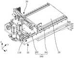
图1为本公开实施例提供的取货装置的结构示意图;FIG. 1 is a schematic structural diagram of a pickup device according to an embodiment of the present disclosure;
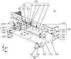
图2为图1中的夹取机构的第一视角立体结构示意图;Fig. 2 is the first perspective three-dimensional structural schematic diagram of the clamping mechanism in Fig. 1;
图3为图1中的夹取机构的第二视角立体结构示意图;FIG. 3 is a schematic three-dimensional structural diagram of the clamping mechanism in FIG. 1 from a second perspective;
图4为图1中的夹取机构夹取货箱时的结构示意图;4 is a schematic structural diagram of the gripping mechanism in FIG. 1 when gripping the cargo box;
图5为图4中的夹取机构将货箱拉动至托盘上时的结构示意图。FIG. 5 is a schematic structural diagram when the gripping mechanism in FIG. 4 pulls the cargo box onto the pallet.
附图标记说明:Description of reference numbers:
10-伸缩机构;10- telescopic mechanism;
110-传动带;110 - Transmission belt;
20-托盘;20 - tray;
30-夹取机构;30-Clamping mechanism;
310-安装板; 311-第一通孔; 312-连接板;310-installation plate; 311-first through hole; 312-connection plate;
320-滑动件; 330-夹取件; 331-连接臂;320-Sliding piece; 330-Clamping piece; 331-Connecting arm;
332-第一转轴; 333-伸出臂; 334-第二转轴;332-first shaft; 333-extending arm; 334-second shaft;
340-调整板; 341-防滑垫; 342-防滑凸起;340-Adjustment plate; 341-Anti-slip pad; 342-Anti-slip bump;
350-导向组件; 351-导向座; 352-底板;350-guide assembly; 351-guide seat; 352-base plate;
353-第二滑槽; 354-侧板; 355-导向轴;353-second chute; 354-side plate; 355-guide shaft;
356-第二通孔; 357-导向臂; 358-第一滑槽;356-second through hole; 357-guide arm; 358-first chute;
359-导向杆; 360-驱动组件; 361-轴承座;359-guide rod; 360-drive assembly; 361-bearing seat;
362-传动丝杠; 363-电机; 364-传动螺母;362-drive screw; 363-motor; 364-drive nut;
370-滑动导向组件; 371-第一导轨; 372-第一滑块;370-slide guide assembly; 371-first guide rail; 372-first slider;
380-连接组件; 381-第一夹板; 382-第二夹板;380-connection assembly; 381-first splint; 382-second splint;
390-伸缩导向组件; 391-第二导轨; 392-第二滑块;390-Telescopic guide assembly; 391-Second guide rail; 392-Second slider;
40-货箱。40 - Cargo box.
具体实施方式Detailed ways
相关技术中的夹取机构在取货时,夹取机构的两个夹取臂伸入至待取货箱的两侧,对货箱进行夹取,向货箱施加一定的夹持力,然后两个夹取臂将货箱从货架上拉动至托盘上。然而,在将货架上的货箱从货架上拉动至托盘上的过程中,货箱与货架或托盘之间产生摩擦力,使得货箱受到与取货方向相反的力,夹取臂对货箱的夹持力较小,使得夹取臂与货箱容易脱开,从而使得取货装置无法完成取货功能。When the gripping mechanism in the related art picks up the goods, the two gripping arms of the gripping mechanism extend into the two sides of the to-be-fetched box to grip the cargo box, apply a certain clamping force to the cargo box, and then. Two gripping arms pull the case from the rack to the pallet. However, in the process of pulling the case on the shelf from the shelf to the pallet, frictional force is generated between the case and the shelf or pallet, so that the case is subjected to a force opposite to the pickup direction, and the gripping arm is opposite to the case. The gripping force is small, so that the gripping arm and the cargo box are easily disengaged, so that the picking device cannot complete the picking function.
有鉴于此,本公开实施例提供一种夹取机构,包括两个夹取件及两个调整板,每个夹取件包括相连接的连接臂和伸出臂,连接臂的一端通过第一转轴与对应的滑动件沿第三方向转动连接,每个调整板通过第二转轴与对应的伸出臂的一端沿第三方向转动连接。在夹取机构将货箱拉动至托盘上的过程中,两个调整板分别夹持料箱的两侧,调整板受到货箱向其施加的与取货方向相反的力,由于调整板通过第二转轴与伸出臂转动连接,且连接臂通过第一转轴与滑动件转动连接,使得两个连接臂相对滑动件转动,从而使两个调整板相互靠近,以夹紧货箱,从而增大调整板对货箱的夹持力,防止调整板与货箱脱开,保证取货装置的取货功能。In view of this, an embodiment of the present disclosure provides a clamping mechanism, which includes two clamping members and two adjusting plates, each clamping member includes a connecting arm and an extension arm that are connected, and one end of the connecting arm passes through the first rotating shaft Rotatingly connected with the corresponding sliding piece along the third direction, each adjustment plate is rotatably connected with one end of the corresponding extending arm along the third direction through the second rotating shaft. In the process of pulling the cargo box onto the pallet by the gripping mechanism, the two adjusting plates respectively clamp the two sides of the bin, and the adjusting plates are subjected to the force opposite to the picking direction exerted by the cargo box on them. The second rotating shaft is rotatably connected with the extension arm, and the connecting arm is rotatably connected with the sliding member through the first rotating shaft, so that the two connecting arms rotate relative to the sliding member, so that the two adjusting plates are close to each other to clamp the cargo box, thereby increasing the The clamping force of the adjustment plate on the cargo box is prevented to prevent the adjustment plate from being disengaged from the cargo box, so as to ensure the pickup function of the pickup device.
为使本公开实施例的目的、技术方案和优点更加清楚,下面将结合本公开实施例中的附图,对本公开实施例中的技术方案进行清楚、完整地描述,显然,所描述的实施例是本公开一部分实施例,而不是全部的实施例。基于本公开中的实施例,本领域普通技术人员在没有作出创造性劳动前提下所获得的所有其他实施例,都属于本公开保护的范围。In order to make the purposes, technical solutions and advantages of the embodiments of the present disclosure clearer, the technical solutions in the embodiments of the present disclosure will be described clearly and completely below with reference to the accompanying drawings in the embodiments of the present disclosure. Obviously, the described embodiments These are some, but not all, embodiments of the present disclosure. Based on the embodiments in the present disclosure, all other embodiments obtained by those of ordinary skill in the art without creative efforts shall fall within the protection scope of the present disclosure.
参考图1,本公开实施例提供一种取货装置,应用于搬运机器人上,包括伸缩机构10、托盘20和夹取机构30,伸缩机构10与夹取机构30连接,用于驱动夹取机构30在托盘20的上方沿第一方向,即图1中所示y方向滑动。托盘20用于盛放货箱。当取货装置取货时,伸缩机构10驱动夹取机构30在托盘20的上方向托盘20朝向货架等存放货箱处的一端移动,夹取机构30夹取货箱;伸缩机构10再次驱动夹取机构30及货箱在托盘20的上方向托盘20背向货架等的一端移动,从而将货箱拉动至托盘20上。Referring to FIG. 1 , an embodiment of the present disclosure provides a pickup device, which is applied to a handling robot, including a
本公开实施例的取货装置,伸缩机构10与夹取机构30相互独立设置,且伸缩机构10与夹取机构30相连接,伸缩机构10驱动夹取机构30在托盘20的上方沿第一方向y滑动至取货位置,夹取机构30夹取货箱。与相关技术中具有伸缩功能的夹取机构相比,本公开实施例中夹取机构30的结构简单,夹取货箱时所需的空间较小,即相邻的货箱之间可以留有较小的空间夹取机构30即可进行货箱的夹取,提高了货架等用于存放货箱的装置的空间利用率。In the pickup device of the embodiment of the present disclosure, the
示例性地,伸缩机构10可以为带传动,例如伸缩机构10可以包括传动轮及与传动轮相啮合的传动带110,夹取机构30与传动带110连接。传动轮转动时能够带动传动带110移动,从而带动夹取机构30移动。可以理解的是,伸缩机构10也可以为链条传动等。Exemplarily, the
参考图2和图3,本公开实施例的夹取机构30,包括安装板310、两个滑动件320、两个夹取件330和两个相对设置的调整板340,安装板310沿与托盘20平行的第一方向y滑动设置于托盘20的上方。两个滑动件320均与安装板310沿第二方向,即沿图2中所示的x方向滑动连接,第二方向x平行托盘20,且与第一方向y垂直。每个夹取件330包括连接臂331和伸出臂333,每个连接臂331的第一端通过第一转轴332与对应的滑动件320沿第三方向,即沿图2中所示的z方向转动连接,第三方向z垂直托盘20,每个连接臂331的第二端与伸出臂333的第一端连接。两个调整板340与两个伸出臂333一一对应。每个调整板340通过第二转轴334与对应的伸出臂333的第二端沿第三方向z转动连接。在夹取机构30将货箱拉动至托盘20上的过程中,两个连接臂331相对滑动件320转动,使两个调整板340相互靠近。Referring to FIGS. 2 and 3 , the
本公开实施例的夹取机构,在从货架等处进行取货时,两个伸出臂333分别位于货箱的两侧,使得两个调整板340分别位于货箱的两侧。夹取机构30的两个滑动件320相向滑动,通过连接臂331和伸出臂333带动两个调整板340相向移动,以夹持货箱。夹取机构30向远离货架的方向移动,以将货箱拉动至托盘20上。在夹取机构30将货箱拉动至托盘20上的过程中,货箱与货架或托盘20之间产生摩擦力,使得货箱受到与取货方向相反的力,则调整板340也受到货箱向其施加的与取货方向相反的力。由于调整板340通过第二转轴334与伸出臂333转动连接,且连接臂331通过第一转轴332与滑动件320转动连接,使得两个连接臂331相对滑动件320转动,从而使两个调整板340相互靠近,以夹紧货箱,从而增大了调整板340对货箱的夹持力,防止调整板340与货箱脱开,保证取货装置的取货功能。In the gripping mechanism of the embodiment of the present disclosure, when picking up goods from a shelf or the like, the two extending
安装板310用于支撑滑动件320、夹取件330及调整板340。示例性地,参考图2,安装板310位于托盘20的上方,安装板310可以垂直托盘20,安装板310的下方设置有平行于托盘20的连接板312。夹取机构30还包括连接组件380,连接板312通过连接组件380与伸缩机构10连接。The mounting
示例性地,连接组件380可以包括第一夹板381和第二夹板382,第一夹板381连接于连接板312的底面。第二夹板382与第一夹板381相对设置且连接,例如,第二夹板382和第一夹板381可通过螺栓连接,从而将伸缩机构10的传动带110夹设于第二夹板382与第一夹板381之间。示例性地,第二夹板382朝向第一夹板381的侧面,即与传动带110相接触的侧面上可以设置有齿状结构,以与传动带110的传动齿相啮合,增加与传动带110的接触面积,从而增加连接组件380与传动带110的连接强度。Exemplarily, the connecting
参考图2,夹取机构30还可以包括伸缩导向组件390,伸缩导向组件390连接连接板312和伸缩机构10,用于对连接板312在第一方向上,即在y方向上的滑动进行导向,以在取货或放货的过程中,提高夹取机构30移动时的平稳性。Referring to FIG. 2 , the
在本公开实施例的一些实现方式中,参考图1,伸缩导向组件390可以包括第二导轨391和第二滑块392,第二导轨391沿第一方向y安装于伸缩机构10上,第二滑块392滑设于第二导轨391上,第二滑块392连接于连接板312的底面。当伸缩机构10驱动夹取机构30进行移动时,连接于连接板312的底面第二滑块392能够在第二导轨391上滑动,从而能够对连接板312及安装板310进行导向,提高安装板310移动时的平稳性,进而提高夹取机构30移动时的平稳性。In some implementations of the embodiments of the present disclosure, referring to FIG. 1 , the
在本公开实施例的一些其他实现方式中,伸缩导向组件390还可以包括设置于伸缩机构10上的滑槽及设置于连接板312底面上的第三滑块(附图中未示出),滑槽沿第一方向y设置,第三滑块滑设于滑槽内,当伸缩机构10驱动夹取机构30进行移动时,连接板312上的第三滑块能够在伸缩机构10的滑槽内滑动,从而实现对连接板312及安装板310的导向,从而实现对夹取机构30的导向,提高了夹取机构30移动时的平稳性。In some other implementations of the embodiments of the present disclosure, the
安装板310上设置有两个滑动件320,两个滑动件320与安装板310在第二方向上滑动连接,两个滑动件320能够在第二方向上相对或相背滑动,以带动两个夹取件330相互靠近或相互远离,从而实现夹取或放开货箱。The mounting
示例性地,参考图3,滑动件320可以为板状结构,滑动件320与安装板310平行设置,滑动件320与安装板310之间设置有滑动导向组件370,滑动导向组件370连接安装板310和滑动件320,用于对滑动件320在第二方向x上的滑动进行导向,且滑动件320通过滑动导向组件370与安装板310滑动连接。Exemplarily, referring to FIG. 3 , the sliding
示例性地,滑动导向组件370可以包括第一导轨371和第一滑块372,第一导轨371沿第二方向x安装于安装板310上,第一滑块372滑设于第一导轨371上,第一滑块372与滑动件320连接。滑动件320滑动时,能够带动第一滑块372在第一导轨371上进行滑动,第一滑块372和第一导轨371对滑动件320起到导向的作用。Exemplarily, the sliding
参考图2,夹取机构30还可以包括驱动组件360,驱动组件360与两个滑动件320连接,用于驱动两个滑动件320沿第二方向x相向或相背滑动。Referring to FIG. 2 , the gripping
示例性地,驱动组件360可以包括轴承座361、传动丝杠362、电机363和两个传动螺母364,轴承座361安装于安装板310上。传动丝杠362沿第二方向x设置,传动丝杠362穿设于轴承座361内。传动丝杠362能够在轴承座361内绕传动丝杠362的轴线转动。轴承座361的数量可以有两个,两个轴承座361沿第二方向x间隔设置,传动丝杠362穿设于两个轴承座361内,两个轴承座361均对传动丝杠362进行支撑,提高了对传动丝杠362的支撑稳定性,从而提高了传动丝杠362转动时的稳定性。电机363与传动丝杠362的一端连接,用于驱动传动丝杠362转动。传动丝杠362的外圆周面的两端设置有旋向相反的外螺纹,两个传动螺母364分别螺纹连接于传动丝杠362两端的外螺纹上,两个传动螺母364分别与两个滑动件320连接。Exemplarily, the drive assembly 360 may include a
电机363的输出轴转动时,驱动传动丝杠362绕自身轴线转动,两个传动螺母364在传动丝杠362两端的外螺纹的作用下相互靠近或相互远离,从而带动两个滑动件320沿第二方向x相向或相背滑动。When the output shaft of the
每个滑动件320均对应设置有一个夹取件330,两个滑动件320相向或相背滑动时,能够带动两个夹取件330相互靠近或相互远离,以对货箱进行夹持或放开。Each sliding
参考图3和图4,每个夹取件330可以包括相连接的连接臂331和伸出臂333。每个连接臂331的第一端通过第一转轴332与对应的滑动件320沿第三方向z转动连接,每个连接臂331的第二端与伸出臂333的第一端连接。两个调整板340与两个伸出臂333一一对应,每个调整板340通过第二转轴334与对应的伸出臂333的第二端沿第三方向z转动连接,调整板340用于夹持货箱40。Referring to FIGS. 3 and 4 , each
夹取机构30取货时,参考图4,电机363驱动传动丝杠362转动时,两个传动螺母364分别带动两个滑动件320相向滑动,两个滑动件320分别通过两个夹取件330带动两个调整板340相互靠近,以夹持货箱40。在夹取机构30将货箱40拉动至托盘20上的过程中,参考图5,两个连接臂331相对对应的滑动件320按C方向转动,使得两个调整板340沿D方向相互靠近,从而增大调整板340与货箱40之间的夹持力,能够防止调整板240与货箱40脱开。When the
此外,本公开实施例的夹取机构30在将货箱40拉动至托盘20上的过程中,两个调整板240会相互靠近,两个调整板240对货箱40的夹持力会逐渐增大。因此当电机363驱动两个滑动件320相向滑动,两个滑动件320通过连接臂331和伸出臂333带动两个调整板340夹持货箱时,仅需对货箱提供较小的初始夹持力即可,从而降低了对电机363的功率的要求。In addition, in the process of pulling the
示例性地,参考图4和图5,连接臂331与伸出臂333可以相互垂直,第一转轴332与伸出臂333之间的距离为第一距离a,第二转轴334与连接臂331之间的距离为第二距离b,第一距离与第二距离之间满足关系式:μa≥b;其中,μ为调整板与货箱之间的摩擦系数。4 and 5 , the connecting
夹取机构30取货时,两个调整板240夹持货箱40,调整板240受到货箱40向其施加的推力N。在夹取机构30将货箱40拉动至托盘20上的过程中,夹取机构30在伸缩机构10的驱动下向A方向滑动,货箱40受到货架或托盘20的摩擦力,使得货箱40具有向B方向移动的趋势,调整板240受到货箱40向其施加的拉力F,推力N与拉力F均作用于第二转轴334的轴线上。由于F=μN,拉力F对连接臂331施加的第一力矩为μN×a。推力N向连接臂331施加的第二力矩为N×b。由于μa≥b,则第一力矩大于等于第二力矩,使得连接臂331向货箱40的方向转动,即向图5中所示的C方向转动,从而使得两个调整板340相互靠近,增大了调整板340与货箱40之间的夹持力,能够防止货箱40与调整板340脱开。When the
示例性地,第一距离a大于或等于两倍的第二距离b。例如,第一距离a可以等于两倍的第二距离b,或第一距离a可以等于三倍的第二距离b。Exemplarily, the first distance a is greater than or equal to twice the second distance b. For example, the first distance a may be equal to twice the second distance b, or the first distance a may be equal to three times the second distance b.
可以理解的是,连接臂331和伸出臂333也可以不相互垂直。在连接臂331处于平行第二方向,即平行图4中所示的x方向的状态时,第一转轴332与第二转轴334之间的距离在第二方向x上的投影距离为第一投影距离,第一转轴332与第二转轴334之间的距离在第一方向y上的投影距离为第二投影距离,只要第一投影距离大于或等于μ倍的第二投影距离即可。It can be understood that, the connecting
参考图2和图3,夹取机构还可以包括导向组件350,导向组件350设置于安装板310上,且与两个连接臂331连接,用于对两个连接臂331在第二方向x上的滑动及在第三方向z上的转动进行导向,以提高连接臂331移动时的平稳性。Referring to FIGS. 2 and 3 , the clamping mechanism may further include a
示例性地,导向组件350包括导向座351、导向轴355和两个导向臂357,导向座351与安装板310连接。导向轴355与导向座351沿第一方向y滑动连接。两个导向臂357与两个连接臂331一一对应,每个导向臂357的第一端与对应的连接臂331连接,每个导向臂357的第二端均设置有第一滑槽358,第一滑槽358沿与连接臂331平行的方向设置,导向臂357的第二端通过第一滑槽358套设于导向轴335上。Exemplarily, the
参考图4,当两个滑动件320相向滑动时,两个滑动件320分别驱动两个连接臂331在第二方向x上相向滑动,每个导向臂357的第一滑槽358套设于导向轴355上,使得两个导向臂357在第一滑槽358及导向轴355的作用下在x方向上相向滑动,以对两个连接臂331在第二方向x上的滑动进行导向。Referring to FIG. 4 , when the two sliding
参考图5,当两个连接臂331绕第一转轴320相对两个滑动件320转动时,两个连接臂331分别带动两个导向臂357绕第一转轴320转动,两个导向臂357第二端的第一滑槽358相对于导向轴355转动,且第一滑槽358的槽壁推动导向轴355相对于导向座351沿第一方向y向远离货箱40的方向移动,从而对两个连接臂331在第三方向z上的转动进行导向。5 , when the two connecting
示例性地,参考图2,安装板310可以与托盘20垂直,安装板310上设置有两个第一通孔311,两个第一通孔311与两个导向臂357对应设置,每个导向臂357穿设于对应的第一通孔311内。导向座351与连接臂331分别位于安装板310的两侧,导向座351与安装板310连接。由于导向座351与连接臂331分别位于安装板310的两侧,避免导向座351占用连接臂331与调整板240之间的夹取空间,使得夹取机构30的结构更加紧凑,提高了取货装置的空间利用率。Exemplarily, referring to FIG. 2 , the mounting
示例性地,参考图2和图3,导向座351可以包括两个底板352,两个底板352的第一端均与安装板310连接;每个底板352上均设置有第二滑槽353,第二滑槽353沿第一方向y设置,导向轴355的两端分别滑设于两个第二滑槽353内。导向轴355通过第二滑槽353与导向座351滑动连接。Exemplarily, referring to FIG. 2 and FIG. 3 , the
导向座351还可以包括侧板354,侧板354连接两个底板352的第二端。导向组件350还包括导向杆359,导向杆359沿第一方向y设置,导向杆359的一端与侧板354连接,导向杆359的另一端与安装板310连接。导向轴355上设置有第二通孔356,导向轴355通过第二通孔356套设于导向杆359上。当导向轴355在第二滑槽353内滑动时,导向轴355能够通过第二通孔356沿导向杆359滑动,导向杆359能够对导向轴355起到导向的作用,提高了导向轴355移动时的平稳性。The
示例性地,导向组件50还可以包括压簧(图中未示出),压簧套设于导向杆359上,压簧的第一端与导向轴355抵接,压簧的第二端与侧板354抵接。当夹取机构30将货箱40拉动至托盘20时,两个连接臂331相对两个滑动件320转动,两个导向臂357的第二滑槽353推动导向轴355沿第一滑槽358向远离货箱40的方向滑动,压簧受到压缩产生形变。当夹取机构30将货箱40拉动至托盘20上之后,夹取机构30停止动作,压簧的形变恢复,压簧向导向轴355施加推力,使导向轴355沿第一滑槽358向货箱40方向滑动,导向轴355通过第二滑槽353推动两个导向臂357及连接臂331反向转动,以实现连接臂331的复位。Exemplarily, the guide assembly 50 may further include a compression spring (not shown in the figure), the compression spring is sleeved on the
参考图3,调整板340与另一个调整板340相对的侧面设置有防滑垫341,以增大调整板340与货箱40之间的摩擦力,防止货箱40与调整板340脱开。3 , an
示例性地,防滑垫341的一侧具有防滑凸起342,防滑凸起342用于接触货箱40,以增大防滑垫341与货箱40接触表面的粗糙度,增加防滑垫341与货箱40之间的摩擦力,进一步防止货箱40与调整板340脱开。Exemplarily, one side of the
本公开实施例还提供一种搬运机器人,包括上述实施例的取货装置。An embodiment of the present disclosure further provides a handling robot, including the pickup device of the above embodiment.
本公开实施例的搬运机器人,由于包括上述取货装置,因此该搬运机器人也具有上述取货装置的优点,在此不再赘述。Since the handling robot of the embodiment of the present disclosure includes the above-mentioned picking device, the handling robot also has the advantages of the above-mentioned picking device, which will not be repeated here.
最后应说明的是:以上各实施例仅用以说明本公开的技术方案,而非对其限制;尽管参照前述各实施例对本公开进行了详细的说明,本领域的普通技术人员应当理解:其依然可以对前述各实施例所记载的技术方案进行修改,或者对其中部分或者全部技术特征进行等同替换;而这些修改或者替换,并不使相应技术方案的本质脱离本公开各实施例技术方案的范围。Finally, it should be noted that the above embodiments are only used to illustrate the technical solutions of the present disclosure, but not to limit them; although the present disclosure has been described in detail with reference to the foregoing embodiments, those of ordinary skill in the art should understand that: The technical solutions described in the foregoing embodiments can still be modified, or some or all of the technical features thereof can be equivalently replaced; and these modifications or replacements do not make the essence of the corresponding technical solutions deviate from the technical solutions of the embodiments of the present disclosure. scope.
Claims (21)
Priority Applications (1)
| Application Number | Priority Date | Filing Date | Title |
|---|---|---|---|
| CN202123317291.1UCN216945158U (en) | 2021-12-24 | 2021-12-24 | Clamping mechanism, goods taking device and transfer robot |
Applications Claiming Priority (1)
| Application Number | Priority Date | Filing Date | Title |
|---|---|---|---|
| CN202123317291.1UCN216945158U (en) | 2021-12-24 | 2021-12-24 | Clamping mechanism, goods taking device and transfer robot |
Publications (1)
| Publication Number | Publication Date |
|---|---|
| CN216945158Utrue CN216945158U (en) | 2022-07-12 |
Family
ID=82312763
Family Applications (1)
| Application Number | Title | Priority Date | Filing Date |
|---|---|---|---|
| CN202123317291.1UActiveCN216945158U (en) | 2021-12-24 | 2021-12-24 | Clamping mechanism, goods taking device and transfer robot |
Country Status (1)
| Country | Link |
|---|---|
| CN (1) | CN216945158U (en) |
Cited By (2)
| Publication number | Priority date | Publication date | Assignee | Title |
|---|---|---|---|---|
| CN117566308A (en)* | 2024-01-15 | 2024-02-20 | 广州龙之音电子科技有限公司 | A warehouse cargo handling shuttle robot |
| WO2025001755A1 (en)* | 2023-06-27 | 2025-01-02 | 深圳市海柔创新科技有限公司 | Pallet fork device and transfer robot |
- 2021
- 2021-12-24CNCN202123317291.1Upatent/CN216945158U/enactiveActive
Cited By (3)
| Publication number | Priority date | Publication date | Assignee | Title |
|---|---|---|---|---|
| WO2025001755A1 (en)* | 2023-06-27 | 2025-01-02 | 深圳市海柔创新科技有限公司 | Pallet fork device and transfer robot |
| CN117566308A (en)* | 2024-01-15 | 2024-02-20 | 广州龙之音电子科技有限公司 | A warehouse cargo handling shuttle robot |
| CN117566308B (en)* | 2024-01-15 | 2024-05-31 | 广州龙之音电子科技有限公司 | Warehouse cargo handling shuttle robot |
Similar Documents
| Publication | Publication Date | Title |
|---|---|---|
| CN216945158U (en) | Clamping mechanism, goods taking device and transfer robot | |
| EP3919413A1 (en) | Transport robot and fork assembly thereof | |
| WO2022094876A1 (en) | Automatic palletizing device for logistics unloading, and method therefor | |
| CN114394437B (en) | Mechanical type is transferred and is loaded pile up neatly machinery hand | |
| WO2023274320A1 (en) | Fork assembly, transfer robot, and warehousing system | |
| CN116588860B (en) | Grabbing and positioning mechanism of stacker | |
| CN220376285U (en) | Fork device and transfer robot | |
| CN113305819A (en) | Mechanical arm for carrying logistics | |
| CN219136289U (en) | Fork components and storage robots | |
| CN219488842U (en) | A warehouse logistics robot | |
| CN210256211U (en) | Automatic change mechanical arm device | |
| CN212923508U (en) | Object taking and placing device | |
| CN111185932B (en) | Robot snatchs mechanism | |
| CN108974761A (en) | A kind of automatic loading and unloading loading system | |
| CN110386389B (en) | Grabbing device | |
| CN115648167B (en) | Multifunctional robot for transferring and storing materials | |
| JP7733121B2 (en) | Robot Hand | |
| CN215325526U (en) | Fuel cell stack loading transfer trolley | |
| CN213293966U (en) | A haulage equipment for shifting wafer box goods shelves | |
| CN211590149U (en) | Robot and conveyance device | |
| CN118684004B (en) | Vision-based stacking control system and method | |
| CN221216223U (en) | Palletizing robot | |
| CN215905812U (en) | Pallet fork device and transfer robot | |
| CN217477191U (en) | Commodity circulation transportation is with transportation frame coupling assembling | |
| CN215202041U (en) | Magnetic gripping device capable of realizing rigid-flexible switching of robot |
Legal Events
| Date | Code | Title | Description |
|---|---|---|---|
| GR01 | Patent grant | ||
| GR01 | Patent grant |