CN216796687U - Sole structure for an article of footwear - Google Patents
Sole structure for an article of footwearDownload PDFInfo
- Publication number
- CN216796687U CN216796687UCN202121888611.6UCN202121888611UCN216796687UCN 216796687 UCN216796687 UCN 216796687UCN 202121888611 UCN202121888611 UCN 202121888611UCN 216796687 UCN216796687 UCN 216796687U
- Authority
- CN
- China
- Prior art keywords
- sole structure
- bladder
- plate
- end support
- bracket
- Prior art date
- Legal status (The legal status is an assumption and is not a legal conclusion. Google has not performed a legal analysis and makes no representation as to the accuracy of the status listed.)
- Active
Links
Images


Classifications
- A—HUMAN NECESSITIES
- A43—FOOTWEAR
- A43B—CHARACTERISTIC FEATURES OF FOOTWEAR; PARTS OF FOOTWEAR
- A43B13/00—Soles; Sole-and-heel integral units
- A43B13/14—Soles; Sole-and-heel integral units characterised by the constructive form
- A43B13/18—Resilient soles
- A43B13/181—Resiliency achieved by the structure of the sole
- A43B13/186—Differential cushioning region, e.g. cushioning located under the ball of the foot
- A—HUMAN NECESSITIES
- A43—FOOTWEAR
- A43B—CHARACTERISTIC FEATURES OF FOOTWEAR; PARTS OF FOOTWEAR
- A43B13/00—Soles; Sole-and-heel integral units
- A43B13/14—Soles; Sole-and-heel integral units characterised by the constructive form
- A43B13/18—Resilient soles
- A43B13/20—Pneumatic soles filled with a compressible fluid, e.g. air, gas
- A—HUMAN NECESSITIES
- A43—FOOTWEAR
- A43B—CHARACTERISTIC FEATURES OF FOOTWEAR; PARTS OF FOOTWEAR
- A43B13/00—Soles; Sole-and-heel integral units
- A43B13/14—Soles; Sole-and-heel integral units characterised by the constructive form
- A—HUMAN NECESSITIES
- A43—FOOTWEAR
- A43B—CHARACTERISTIC FEATURES OF FOOTWEAR; PARTS OF FOOTWEAR
- A43B13/00—Soles; Sole-and-heel integral units
- A43B13/14—Soles; Sole-and-heel integral units characterised by the constructive form
- A43B13/18—Resilient soles
- A43B13/181—Resiliency achieved by the structure of the sole
- A43B13/182—Helicoidal springs
- A—HUMAN NECESSITIES
- A43—FOOTWEAR
- A43B—CHARACTERISTIC FEATURES OF FOOTWEAR; PARTS OF FOOTWEAR
- A43B13/00—Soles; Sole-and-heel integral units
- A43B13/14—Soles; Sole-and-heel integral units characterised by the constructive form
- A43B13/18—Resilient soles
- A43B13/181—Resiliency achieved by the structure of the sole
- A43B13/184—Resiliency achieved by the structure of the sole the structure protruding from the outsole
- A—HUMAN NECESSITIES
- A43—FOOTWEAR
- A43B—CHARACTERISTIC FEATURES OF FOOTWEAR; PARTS OF FOOTWEAR
- A43B13/00—Soles; Sole-and-heel integral units
- A43B13/14—Soles; Sole-and-heel integral units characterised by the constructive form
- A43B13/18—Resilient soles
- A43B13/181—Resiliency achieved by the structure of the sole
- A43B13/185—Elasticated plates sandwiched between two interlocking components, e.g. thrustors
- A—HUMAN NECESSITIES
- A43—FOOTWEAR
- A43B—CHARACTERISTIC FEATURES OF FOOTWEAR; PARTS OF FOOTWEAR
- A43B13/00—Soles; Sole-and-heel integral units
- A43B13/14—Soles; Sole-and-heel integral units characterised by the constructive form
- A43B13/18—Resilient soles
- A43B13/187—Resiliency achieved by the features of the material, e.g. foam, non liquid materials
- A—HUMAN NECESSITIES
- A43—FOOTWEAR
- A43B—CHARACTERISTIC FEATURES OF FOOTWEAR; PARTS OF FOOTWEAR
- A43B13/00—Soles; Sole-and-heel integral units
- A43B13/14—Soles; Sole-and-heel integral units characterised by the constructive form
- A43B13/18—Resilient soles
- A43B13/189—Resilient soles filled with a non-compressible fluid, e.g. gel, water
- A—HUMAN NECESSITIES
- A43—FOOTWEAR
- A43B—CHARACTERISTIC FEATURES OF FOOTWEAR; PARTS OF FOOTWEAR
- A43B13/00—Soles; Sole-and-heel integral units
- A43B13/38—Built-in insoles joined to uppers during the manufacturing process, e.g. structural insoles; Insoles glued to shoes during the manufacturing process
- A43B13/40—Built-in insoles joined to uppers during the manufacturing process, e.g. structural insoles; Insoles glued to shoes during the manufacturing process with cushions
- A—HUMAN NECESSITIES
- A43—FOOTWEAR
- A43B—CHARACTERISTIC FEATURES OF FOOTWEAR; PARTS OF FOOTWEAR
- A43B17/00—Insoles for insertion, e.g. footbeds or inlays, for attachment to the shoe after the upper has been joined
- A43B17/02—Insoles for insertion, e.g. footbeds or inlays, for attachment to the shoe after the upper has been joined wedge-like or resilient
- A43B17/03—Insoles for insertion, e.g. footbeds or inlays, for attachment to the shoe after the upper has been joined wedge-like or resilient filled with a gas, e.g. air
- A—HUMAN NECESSITIES
- A43—FOOTWEAR
- A43B—CHARACTERISTIC FEATURES OF FOOTWEAR; PARTS OF FOOTWEAR
- A43B21/00—Heels; Top-pieces or top-lifts
- A43B21/24—Heels; Top-pieces or top-lifts characterised by the constructive form
- A43B21/32—Resilient supports for the heel of the foot
- A—HUMAN NECESSITIES
- A43—FOOTWEAR
- A43B—CHARACTERISTIC FEATURES OF FOOTWEAR; PARTS OF FOOTWEAR
- A43B3/00—Footwear characterised by the shape or the use
- A43B3/0036—Footwear characterised by the shape or the use characterised by a special shape or design
- A43B3/0057—S-shaped
- A—HUMAN NECESSITIES
- A43—FOOTWEAR
- A43B—CHARACTERISTIC FEATURES OF FOOTWEAR; PARTS OF FOOTWEAR
- A43B3/00—Footwear characterised by the shape or the use
- A43B3/0036—Footwear characterised by the shape or the use characterised by a special shape or design
- A43B3/0063—U-shaped
- A—HUMAN NECESSITIES
- A43—FOOTWEAR
- A43B—CHARACTERISTIC FEATURES OF FOOTWEAR; PARTS OF FOOTWEAR
- A43B7/00—Footwear with health or hygienic arrangements
- A43B7/14—Footwear with health or hygienic arrangements with foot-supporting parts
- A43B7/1405—Footwear with health or hygienic arrangements with foot-supporting parts with pads or holes on one or more locations, or having an anatomical or curved form
- A43B7/1415—Footwear with health or hygienic arrangements with foot-supporting parts with pads or holes on one or more locations, or having an anatomical or curved form characterised by the location under the foot
- A43B7/144—Footwear with health or hygienic arrangements with foot-supporting parts with pads or holes on one or more locations, or having an anatomical or curved form characterised by the location under the foot situated under the heel, i.e. the calcaneus bone
- A—HUMAN NECESSITIES
- A43—FOOTWEAR
- A43B—CHARACTERISTIC FEATURES OF FOOTWEAR; PARTS OF FOOTWEAR
- A43B7/00—Footwear with health or hygienic arrangements
- A43B7/14—Footwear with health or hygienic arrangements with foot-supporting parts
- A43B7/1405—Footwear with health or hygienic arrangements with foot-supporting parts with pads or holes on one or more locations, or having an anatomical or curved form
- A43B7/1415—Footwear with health or hygienic arrangements with foot-supporting parts with pads or holes on one or more locations, or having an anatomical or curved form characterised by the location under the foot
- A43B7/1445—Footwear with health or hygienic arrangements with foot-supporting parts with pads or holes on one or more locations, or having an anatomical or curved form characterised by the location under the foot situated under the midfoot, i.e. the second, third or fourth metatarsal
Landscapes
- Health & Medical Sciences (AREA)
- Epidemiology (AREA)
- General Health & Medical Sciences (AREA)
- Public Health (AREA)
- Chemical & Material Sciences (AREA)
- Engineering & Computer Science (AREA)
- Materials Engineering (AREA)
- Footwear And Its Accessory, Manufacturing Method And Apparatuses (AREA)
Abstract
Description
Translated fromChinese相关申请的交叉引用CROSS-REFERENCE TO RELATED APPLICATIONS
本申请根据35 U.S.C.§119(e)要求2020年8月12日提交的美国临时申请US63/064,534的优先权。该在先申请的公开内容被认为是该申请公开内容的一部分,并通过引用将其全部内容结合于此。This application claims priority under 35 U.S.C. §119(e) to US Provisional Application US63/064,534, filed August 12, 2020. The disclosure of this earlier application is considered to be a part of the disclosure of this application, and is hereby incorporated by reference in its entirety.
技术领域technical field
本实用新型总体上涉及一种用于鞋类物品的鞋底结构。The utility model generally relates to a sole structure for footwear articles.
背景技术Background technique
本部分提供与本公开有关的背景信息,其不一定是现有技术。This section provides background information related to the present disclosure which is not necessarily prior art.
鞋类物品通常包括鞋帮和鞋底结构。鞋帮可由任何合适的(多种)材料形成,以在鞋底结构上接收、固定和支撑脚。鞋帮可以与鞋带、带或其他紧固件配合,以调节鞋帮围绕脚的贴合度。靠近脚的底表面的鞋帮的底部部分附接到鞋底结构。Articles of footwear typically include an upper and a sole structure. The upper may be formed from any suitable material(s) to receive, secure, and support the foot on the sole structure. The upper can be fitted with laces, straps or other fasteners to adjust the fit of the upper around the foot. A bottom portion of the upper near the bottom surface of the foot is attached to the sole structure.
鞋底结构通常包括在地面和鞋帮之间延伸的分层布置。鞋底结构的一个层包括外底,其提供对地面的耐磨性和附着力。外底可以由橡胶或赋予耐用性和耐磨性以及增强对地面的附着力的其他材料形成。鞋底结构的另一层包括设置在外底和鞋帮之间的鞋底夹层。鞋底夹层为脚提供缓冲,并且可以部分地由聚合物泡沫材料形成,该聚合物泡沫材料在施加的荷载下弹性压缩以通过减弱地面反作用力来对脚进行缓冲。鞋底夹层可以结合流体填充囊,以通过在施加的载荷下弹性压缩来衰减地面反作用力,从而为脚提供缓冲。鞋底结构还可以包括增强舒适的内底或鞋垫,该内底或鞋垫位于鞋帮的底部部分附近的空隙内,并且鞋底结构包括套楦(strobel),该套楦附接到鞋帮并且设置在鞋底夹层和内底或鞋垫之间。The sole structure typically includes a layered arrangement extending between the ground and the upper. One layer of the sole structure includes the outsole, which provides abrasion resistance and traction to the ground. The outsole may be formed from rubber or other materials that impart durability and abrasion resistance, as well as enhance adhesion to the ground. Another layer of the sole structure includes a midsole disposed between the outsole and the upper. The midsole provides cushioning for the foot and may be formed in part from a polymer foam material that elastically compresses under applied loads to cushion the foot by attenuating ground reaction forces. The midsole may incorporate fluid-filled bladders to provide cushioning for the foot by attenuating ground reaction forces by elastically compressing under applied loads. The sole structure may also include a comfort-enhancing insole or sockliner positioned within the void near the bottom portion of the upper, and the sole structure includes a strobel attached to the upper and disposed in the midsole and between the insole or insole.
使用囊的鞋底夹层通常包括由密封的或结合在一起的两个聚合物材料阻挡层形成的囊。囊可以包含空气,并且设计成强调平衡对脚的支撑和缓冲特性,当囊在施加的载荷下弹性压缩时,缓冲特性与响应性相关。Midsole using bladders typically include a bladder formed from two barrier layers of polymeric material that are sealed or bonded together. The bladder may contain air and be designed to emphasize balanced support and cushioning properties for the foot, which are related to responsiveness when the bladder elastically compresses under an applied load.
实用新型内容Utility model content
在一种构造中,提供了一种用于鞋类物品的鞋底结构,所述鞋底结构包括:缓冲元件,包括第一材料;支架,包括第二材料,附接到所述缓冲元件,并且包括(i)抵靠所述缓冲元件设置的第一板,和(ii)与所述第一板相对地设置的孔口部;外底,包括面对所述缓冲元件的内表面;和囊,设置在所述支架内,并包括第一部分和第二部分,所述第一部分与所述第一板接触,所述第二部分延伸穿过所述孔口部并与所述外底的内表面接触。In one configuration, a sole structure for an article of footwear is provided, the sole structure comprising: a cushioning element including a first material; a bracket including a second material attached to the cushioning element and including (i) a first plate disposed against the cushioning element, and (ii) an aperture portion disposed opposite the first plate; an outsole including an inner surface facing the cushioning element; and a bladder, is disposed within the bracket and includes a first portion in contact with the first plate and a second portion extending through the aperture portion and in contact with the inner surface of the outsole touch.
在另一种构造中,提供了一种用于鞋类物品的鞋底结构,其包括包含第一材料的缓冲元件和包含第二材料的支架。支架附接到缓冲元件,并且包括抵靠缓冲元件设置的第一板和与缓冲元件间隔开的第二板,第二板包括孔口部。鞋底结构还包括设置在支架内的囊,该囊包括接触第一板的第一部分和延伸穿过第二板的孔的第二部分。In another configuration, a sole structure for an article of footwear is provided that includes a cushioning element comprising a first material and a bracket comprising a second material. The bracket is attached to the buffer element and includes a first plate disposed against the buffer element and a second plate spaced from the buffer element, the second plate including an aperture portion. The sole structure also includes a bladder disposed within the bracket, the bladder including a first portion contacting the first plate and a second portion extending through the aperture of the second plate.
鞋底结构可以包括以下可选特征中的一个或多个。例如,外底可以在支架的与缓冲元件相对的一侧上邻近第二板设置。在这种构造中,囊的第二部分可以接触外底。附加地或替代地,第二板可以围绕囊的第二部分。The sole structure may include one or more of the following optional features. For example, the outsole may be positioned adjacent the second panel on the side of the bracket opposite the cushioning element. In this configuration, the second portion of the bladder may contact the outsole. Additionally or alternatively, the second plate may surround the second portion of the bladder.
在一种构造中,第一板和第二板可以部分地限定从第一侧到第二侧连续延伸穿过支架的容纳部。支架可以包括在支架的第一端部处连接第一板和第二板的弓形的第一端部支撑件。第一端部支撑件可以与囊间隔开。附加地或替代地,支架可以包括弓形的第二端部支撑件,该第二端部支撑件在支架的第二端部处连接第一板和第二板。第一端部支撑件和第二端部支撑件可以与囊间隔开。第一端部支撑件可以具有与第二端部支撑件不同的尺寸。In one configuration, the first plate and the second plate may partially define a receptacle extending continuously through the bracket from the first side to the second side. The bracket may include an arcuate first end support connecting the first plate and the second plate at a first end of the bracket. The first end support may be spaced apart from the bladder. Additionally or alternatively, the bracket may include an arcuate second end support connecting the first and second plates at the second end of the bracket. The first end support and the second end support may be spaced apart from the bladder. The first end support may have a different size than the second end support.
在另一种构造中,提供了一种用于鞋类物品的鞋底结构,该鞋底结构包括:缓冲元件;支架,由缓冲元件接收,并限定从鞋底结构的第一侧到鞋底结构的第二侧连续延伸穿过支架的容纳部;以及囊,包括设置在容纳部内的第一部分和延伸穿过支架的第二部分。In another configuration, a sole structure for an article of footwear is provided, the sole structure comprising: a cushioning element; a bracket received by the cushioning element and defining from a first side of the sole structure to a second side of the sole structure a side extending continuously through the receptacle of the stent; and a bladder including a first portion disposed within the receptacle and a second portion extending through the stent.
鞋底结构可以包括以下可选特征中的一个或多个。在一种构造中,外底可以设置在支架的与缓冲元件相对的一侧。在这种构造中,囊的第二部分可以通过支架接触外底。The sole structure may include one or more of the following optional features. In one configuration, the outsole may be disposed on the opposite side of the bracket from the cushioning element. In this configuration, the second portion of the bladder may contact the outsole through the bracket.
在一种构造中,支架可以包括围绕囊的第二部分的第一板。第二板可以与第一板间隔开。在这种构造中,囊的第一部分可以接触第二板。In one configuration, the stent may include a first plate surrounding the second portion of the bladder. The second plate may be spaced apart from the first plate. In this configuration, the first portion of the bladder may contact the second plate.
支架可以包括在支架的第一端部处连接第一板和第二板的弓形的第一端部支撑件。第一端部支撑件可以与囊间隔开。附加地或替代地,支架可以包括弓形的第二端部支撑件,该第二端部支撑件在支架的第二端部处连接第一板和第二板。第一端部支撑件和第二端部支撑件可以与囊间隔开。第一端部支撑件可以具有与第二端部支撑件不同的尺寸。The bracket may include an arcuate first end support connecting the first plate and the second plate at a first end of the bracket. The first end support may be spaced apart from the bladder. Additionally or alternatively, the bracket may include an arcuate second end support connecting the first and second plates at the second end of the bracket. The first end support and the second end support may be spaced apart from the bladder. The first end support may have a different size than the second end support.
附图说明Description of drawings
本文描述的附图仅用于所选构造的说明性目的,而无意限制本公开的范围。在附图中:The drawings described herein are for illustrative purposes of selected constructions only and are not intended to limit the scope of the present disclosure. In the attached image:
图1是根据本实用新型原理的鞋类物品的外侧透视图;1 is an outside perspective view of an article of footwear in accordance with the principles of the present invention;
图2是图1的鞋类物品的内侧透视图;Figure 2 is a medial perspective view of the article of footwear of Figure 1;
图3是图1的鞋类物品的外侧正视图;Fig. 3 is a lateral side elevational view of the article of footwear of Fig. 1;
图4是图1的鞋类物品的俯视图;Fig. 4 is a top view of the article of footwear of Fig. 1;
图5是图1的鞋类物品的鞋底结构的底部透视分解图;5 is a bottom perspective exploded view of the sole structure of the article of footwear of FIG. 1;
图6是图5的鞋底结构的顶部透视分解图;Figure 6 is a top perspective exploded view of the sole structure of Figure 5;
图7是沿着图4的线7-7截取的图1的鞋类物品的剖视图;7 is a cross-sectional view of the article of footwear of FIG. 1 taken along line 7-7 of FIG. 4;
图8是沿着图3的线8-8截取的图1的鞋类物品的剖视图;8 is a cross-sectional view of the article of footwear of FIG. 1 taken along line 8-8 of FIG. 3;
图9是沿着图3的线9-9截取的图1的鞋类物品的剖视图;9 is a cross-sectional view of the article of footwear of FIG. 1 taken along line 9-9 of FIG. 3;
图10是沿着图3的线10-10截取的图1的鞋类物品的剖视图;10 is a cross-sectional view of the article of footwear of FIG. 1 taken along line 10-10 of FIG. 3;
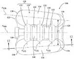
图11是根据本实用新型原理的鞋底结构的囊的俯视图;和11 is a top view of a bladder of a sole structure in accordance with the principles of the present invention; and
图12是沿着图11的线12-12截取的图11的囊的剖视图。12 is a cross-sectional view of the bladder of FIG. 11 taken along line 12-12 of FIG. 11 .
在整个附图中,对应的附图标记表示对应的部分。Corresponding reference characters indicate corresponding parts throughout the drawings.
具体实施方式Detailed ways
现在将参考附图更全面地描述示例实施例。提供示例实施例,使得本公开将是透彻的,并且将本公开的范围充分传达给本领域技术人员。阐述了许多特定细节,例如特定部件、装置和方法的示例,以提供对本公开的构造的透彻理解。对于本领域普通技术人员将显而易见的是,不需要采用具体细节,示例构造可以以许多不同的形式来实施,并且具体细节和示例构造不应被解释为限制本公开的范围。Example embodiments will now be described more fully with reference to the accompanying drawings. Example embodiments are provided so that this disclosure will be thorough, and will fully convey the scope of the disclosure to those skilled in the art. Numerous specific details are set forth, such as examples of specific components, devices, and methods, in order to provide a thorough understanding of the construction of the present disclosure. It will be apparent to those of ordinary skill in the art that specific details need not be employed, that example constructions may be embodied in many different forms and that specific details and example constructions should not be construed as limiting the scope of the disclosure.
本文所使用的术语仅出于描述特定示例实施例的目的,而不旨在进行限制。如本文所使用的,单数形式的“一”、“一个”和“该”也可以意图包括复数形式,除非上下文另外明确指出。术语“包括”、“包含”、“含有”和“具有”是包含性的,因此指定了特征、步骤、操作、元件和/或部件的存在,但不排除一个或多个其他特征、步骤、操作、元件、部件和/或其组合的存在或添加。除非明确地标识为执行顺序,否则本文描述的方法步骤、过程和操作不应被解释为必须以所讨论或示出的特定顺序执行。可以采用附加或替代步骤。The terminology used herein is for the purpose of describing particular example embodiments only and is not intended to be limiting. As used herein, the singular forms "a," "an," and "the" are intended to include the plural forms as well, unless the context clearly dictates otherwise. The terms "comprising", "comprising", "containing" and "having" are inclusive, thus specifying the presence of a feature, step, operation, element and/or component, but not excluding one or more other features, steps, The presence or addition of operations, elements, components, and/or combinations thereof. Method steps, procedures, and operations described herein should not be construed as necessarily being performed in the particular order discussed or shown, unless an order of performance is explicitly identified. Additional or alternative steps may be employed.
当元件或层被称为在另一元件或层的“上面”或“接合到”、“连接到”、“附接到”或“联接到”到另一元件或层时,它可以直接位于、接合、连接、附接或联接到另一元件或层上,或者可以存在中间元件或层。相反,当元件被称为“直接在”另一元件或层“上”或“直接接合到”、“直接连接到”、“直接附接到”或“直接联接到”另一元件或层时,可能不存在中间元件或层。应当以类似的方式来解释用于描述元件之间的关系的其他词语(例如,“在... 之间”与“直接在...之间”,“相邻”与“直接相邻”等)。如本文所使用的,术语“和/或”包括相关联列出的项目中的一个或多个的任何和所有组合。When an element or layer is referred to as being "on" or "bonded to," "connected to," "attached to," or "coupled to" another element or layer, it can be directly on , joined, connected, attached or coupled to another element or layer, or intervening elements or layers may be present. In contrast, when an element is referred to as being "directly on" or "directly joined to," "directly connected to," "directly attached to," or "directly coupled to" another element or layer , there may be no intervening elements or layers. Other words used to describe the relationship between elements should be interpreted in a similar fashion (eg, "between" versus "directly between", "adjacent" versus "directly adjacent" Wait). As used herein, the term "and/or" includes any and all combinations of one or more of the associated listed items.
本文中可以使用术语第一、第二、第三等来描述各种元件,部件,区域,层和/或部分。这些元件,区域,层和/或部分不应受到这些术语的限制。这些术语仅可用于区分一个元件、部件、区域、层或部分与另一区域、层或部分。除非上下文明确指出,否则本文中使用的诸如“第一”、“第二”和其他数字术语之类的术语并不暗示顺序或次序。因此,在不脱离示例实施例的教导的情况下,下面讨论的第一元件,部件,区域,层或部分可以被称为第二元件,部件,区域,层或部分。The terms first, second, third, etc. may be used herein to describe various elements, components, regions, layers and/or sections. These elements, regions, layers and/or sections should not be limited by these terms. These terms are only used to distinguish one element, component, region, layer or section from another region, layer or section. Terms such as "first," "second," and other numerical terms when used herein do not imply a sequence or order unless clearly indicated by the context. Thus, a first element, component, region, layer or section discussed below could be termed a second element, component, region, layer or section without departing from the teachings of example embodiments.
参考图1-10,提供了一种鞋类物品10,其包括鞋底结构100和附接到鞋底结构100的鞋帮200。鞋类物品10可以分为一个或多个区域。区域可以包括前脚区域12、中脚区域14和脚跟区域16。前脚区域12对应于脚的趾骨和跖趾关节(即“球”)。中脚区域14可以对应于脚的足弓区域,而脚跟区域16可以对应于脚的后部部分,包括跟骨。鞋类10还可包括与前脚区域12 的最前点相关联的前端18和与脚跟区域16的最后点对应的后端20。如图5 所示,鞋类10的纵向轴线A10沿着鞋类10的长度从前端18延伸至后端20,并且大体将鞋类10分为外侧22和内侧24。因此,外侧22和内侧24分别对应于鞋类10的相对侧并延伸穿过区域12、14、16。Referring to FIGS. 1-10 , an article of
参考图3,鞋底结构100包括被构造为向鞋底结构100提供缓冲特性的鞋底夹层102和被构造为提供鞋类物品10的地面接合表面30的外底104。与传统的鞋底结构不同,鞋底结构100的鞋底夹层102可以复合形成,并且包括多个子部件,用于在整个鞋底结构100上提供所需形式的缓冲和支撑。例如,鞋底夹层102可被描述为包括囊106和底座108,其中底座108被构造为附接到鞋帮200,并提供鞋帮200、囊106和外底104之间的界面。Referring to FIG. 3 ,
整体上,鞋底结构100的囊106被支撑在底座108的脚跟区域16内,并且被构造成减弱与脚跟区域16中的冲击相关的力。鞋底夹层102的囊106 包括相反的一对阻挡层114、116,它们在不连续的位置彼此连结以限定室 118、腹板区域120和周边接缝122。在所示实施例中,阻挡层114、116包括第一上阻挡层114和第二下阻挡层116。替代地,室118可以由一个或多个阻挡层的任何合适的组合制成,如下面更详细描述的。As a whole,
在一些实施方式中,上阻挡层218a和下阻挡层218b协作以限定室118 的几何形状(例如,厚度,宽度和长度)。例如,腹板区域120和周边接缝 122可以协作以界定室118并绕室118延伸,以密封室118内的流体(例如,空气)。因此,室118与囊106的区域相关,在该区域处上阻挡层114和下阻挡层116的内表面未连结在一起,因此彼此分离。In some embodiments, the upper barrier layer 218a and the lower barrier layer 218b cooperate to define the geometry (eg, thickness, width, and length) of the
如图7和9所示,在上阻挡层114和下阻挡层116的相对的内表面之间形成的空间限定了室118的内腔。类似地,上阻挡层114和下阻挡层116的外表面限定了室118的外部轮廓。室118的厚度T118由囊106的上阻挡层114 和下阻挡层116之间的距离限定。As shown in FIGS. 7 and 9 , the space formed between the opposing inner surfaces of the
如图11最佳所示,室118包括多个部段130、132,这些部段协作以向鞋底夹层102提供响应性和支撑特性。特别地,部段130、132可以被描述为包括在囊106的相反侧上的一对垫130,它们通过一个或多个导管132彼此连接(即,流体连通)。当组装到鞋底结构100中时,室118的垫130被构造成沿着鞋底结构100的周边边缘至少部分暴露。As best shown in FIG. 11 , the
参考图7,每个垫130包括管状体134、设置在管状体134的第一端部处的第一终端136和设置在管状体134的与第一终端136相反的端部处的第二终端138。管状体134限定了沿着垫130的纵向轴线A130延伸的大致圆形的横截面。如图所示,室118的厚度T118沿着纵向轴线A130从第一终端136 处的第一厚度T118-1连续增加到第二终端138处的第二厚度T118-2。因此,室118的厚度可以描述为沿着从第二终端138到第一终端136的方向渐缩 (taper)。7, each
如图12所示,每个垫130的第一终端136和第二终端138基本上是圆顶形的,并且每个都包括与相应的上阻挡层114和下阻挡层116相关联的复合曲率。例如,每个垫130的第一终端136形成在这样的位置,在该位置处,上阻隔层114的端部部分与下阻隔层116会聚并在周边接缝122处连结到下阻隔层116,以封闭管状体134的前端。仍然参考图12,每个垫130的第二终端138形成在这样的位置,在该位置处,上阻挡层114的另一端部部分与下阻挡层116会聚并在周边接缝122处连结到下阻挡层116,以封闭管状体 134的相对端。As shown in FIG. 12 , the
如上所述,每个垫130限定了从第一终端136延伸到第二终端138的相应纵向轴线A130。如图11中最佳示出的,垫130沿着横向于囊106的纵向轴线A106的方向彼此隔开。因此,当囊106被组装在鞋底结构100内时,垫 130沿着鞋类物品10的横向方向彼此隔开,使得垫130中的第一垫沿着外侧 22延伸,垫130中的第二垫130沿着内侧24延伸。此外,垫130的纵向轴线A130沿着从后端20到前端18的方向彼此会聚,并且与鞋类物品10的纵向轴线A10会聚。因此,垫130之间的横向距离D1在第二终端138处大于在第一终端136处。As described above, each
继续参考图11和12,室118还包括至少一个导管132,该至少一个导管132在垫130之间延伸并流体联接垫130。在图示的例子中,室118包括将垫130的管状体134相互连接的多个导管132。导管132每个沿着相应的纵向轴线A132延伸,纵向轴线A132横向于垫130的纵向轴线A130。如图11 和12所示,导管132包括邻近第一终端136在垫130的管状体134之间延伸的第一导管132,邻近第二终端138在垫130的管状体134之间延伸的第二导管132,以及设置在第一导管132和第二导管132之间并连接管状体134 的中间部分的第三导管132。因此,第一导管132和第二导管132设置在第三导管132的相反侧。With continued reference to FIGS. 11 and 12 , the
如图9和12所示,导管132由上阻挡层114和下阻挡层116协作限定。如图12所示,形成上阻挡层114和下阻挡层116以提供多个半圆柱形导管 132,每个导管具有基本相似的第三厚度T118-3,其小于垫130的第一厚度T118-1和第二厚度T118-2。每个导管132的轮廓基本上由上阻挡层114限定,由此上阻挡层114被模制以限定每个导管132的弯曲上部部分,而下阻挡层116被提供为每个导管132的基本平坦的下部部分。尽管下阻挡层114最初以基本平坦的状态提供,但是当室118被加压并且下阻挡层116被偏压远离上阻挡层114时,下阻挡层116可以从腹板区域120凸出,如图7所示。As shown in FIGS. 9 and 12 , the
参考图7和11,腹板区域120形成在上阻挡层114和下阻挡层116的结合区域,并且在室118的每个部段130、132之间延伸并连接它们。具体而言,腹板区域120包括前部,该前部在相应垫130的第一终端136之间延伸并连接它们,并在囊106的前端限定第一终端边缘。腹板区域120的后部在垫130的第二终端138之间延伸并连接它们,并在囊106的后端形成第二终端边缘。腹板区域120的中间部分在导管132中的相邻导管和垫130之间延伸并连接它们。因此,腹板区域120的中间部分可以被室118完全包围。在图示的例子中,腹板区域120相对于流体填充室118的总厚度T118竖直设置在中间。7 and 11 , a
在图示的例子中,室118的腹板区域120和垫130协作以在囊106的与上阻挡层114相关联的第一侧上限定上袋140。这里,导管132可以设置在上袋140内,以沿着上袋140的长度形成凸起和凹陷的交替系列。如下文更详细描述的,底座108可包括构造成在组装鞋底结构100时与上袋140配合的一个或多个特征部。例如,底座108可以包括凹口和突起,其被构造为接合由囊106的导管132形成的凸起和凹陷。In the illustrated example, the
如本文所用,术语“阻挡层”(例如,阻挡层114、116)包括单层或多层膜。在一些实施例中,阻挡层114、116中的一个或两个均由单层膜(单层) 制成(例如,热成型或吹塑成型)。在其他实施例中,阻挡层114、116中的一个或两个均由多层膜(多个子层)制成(例如,热成型或吹塑成型)。在任一方面中,每个层或子层的膜厚度可以在约0.2微米至约1毫米的范围内。在进一步的实施例中,每个层或子层的膜厚度可以在约0.5微米至约500微米的范围内。在另外的实施例中,每个层或子层的膜厚度可以在约1微米至约100 微米的范围内。As used herein, the term "barrier layer" (eg, barrier layers 114, 116) includes single or multilayer films. In some embodiments, one or both of the barrier layers 114, 116 are made from a single layer film (monolayer) (eg, thermoformed or blow molded). In other embodiments, one or both of the barrier layers 114, 116 are made (eg, thermoformed or blow molded) from a multilayer film (sublayers). In either aspect, the film thickness of each layer or sublayer can be in the range of about 0.2 microns to about 1 millimeter. In further embodiments, the film thickness of each layer or sublayer may range from about 0.5 microns to about 500 microns. In further embodiments, the film thickness of each layer or sublayer may range from about 1 micron to about 100 microns.
阻挡层114、116中的一个或两个可以独立地是透明的、半透明的和/或不透明的。例如,上阻挡层114可以是透明的,而下阻挡层116是不透明的。如本文中所使用的,对于阻挡层和/或流体填充室,术语“透明的”是指光以基本上直线穿过阻挡层并且观察者可以看透阻挡层。相比之下,对于不透明的阻挡层,光不穿过阻挡层,并且根本不能清楚地看透阻挡层。半透明的阻挡层落在透明的阻挡层和不透明的阻挡层之间,因为光穿过半透明的层,但是一些光被散射,使得观看者不能清楚地看透该层。One or both of the barrier layers 114, 116 may independently be transparent, translucent and/or opaque. For example, the
阻挡层114、116每个可以由包括一种或多种热塑性聚合物和/或一种或多种可交联聚合物的弹性体材料制成。在一个方面中,弹性体材料可包括一种或多种热塑性弹性体材料,例如一种或多种热塑性聚氨酯(TPU)共聚物,一种或多种乙烯-乙烯醇(EVOH)共聚物等。The barrier layers 114, 116 may each be made of an elastomeric material including one or more thermoplastic polymers and/or one or more crosslinkable polymers. In one aspect, the elastomeric material may include one or more thermoplastic elastomeric materials, such as one or more thermoplastic polyurethane (TPU) copolymers, one or more ethylene-vinyl alcohol (EVOH) copolymers, and the like.
如本文所用,“聚氨酯”是指含有氨基甲酸酯基团(-N(C=O)O-) 的共聚物(包括低聚物)。这些聚氨酯除氨基甲酸酯基团外还可含有其他基团,例如酯,醚,脲,脲基甲酸酯,缩二脲,碳二亚胺,恶唑烷基,异氰尿酸酯,脲二酮,碳酸酯等。在一方面,一种或多种聚氨酯可以通过将一种或多种异氰酸酯与一种或多种多元醇聚合以产生具有(-N(C=O)O-)键的共聚物链来制备。As used herein, "polyurethane" refers to copolymers (including oligomers) containing urethane groups (-N(C=O)O-). These polyurethanes may contain other groups besides urethane groups, such as esters, ethers, ureas, allophanates, biurets, carbodiimides, oxazolidinyls, isocyanurates, Urea dione, carbonate, etc. In one aspect, one or more polyurethanes can be prepared by polymerizing one or more isocyanates with one or more polyols to produce copolymer chains having (-N(C=O)O-) linkages.
用于生产聚氨酯共聚物链的合适的异氰酸酯的实例包括二异氰酸酯,例如芳族二异氰酸酯,脂族二异氰酸酯及其组合。合适的芳族二异氰酸酯的示例包括:甲苯二异氰酸酯(TDI);TDI与三甲酰基丙烷(TMP)的加合物;亚甲基二苯基二异氰酸酯(MDI);二甲苯二异氰酸酯(XDI);四甲基二甲苯二甲苯二异氰酸酯(TMXDI);氢化二甲苯二异氰酸酯(HXDI);萘1,5- 二异氰酸酯(NDI);1,5-四氢萘二异氰酸酯;对亚苯基二异氰酸酯(PPDI); 3,3'-二甲基二苯基1-4、4'-二异氰酸酯(DDDI);4,4'-二苄基二异氰酸酯 (DBDI);4-氯-1,3-亚苯基二异氰酸酯;及其组合。在一些实施例中,共聚物链基本上不含芳族基团。Examples of suitable isocyanates for producing polyurethane copolymer chains include diisocyanates such as aromatic diisocyanates, aliphatic diisocyanates, and combinations thereof. Examples of suitable aromatic diisocyanates include: toluene diisocyanate (TDI); adducts of TDI with triformylpropane (TMP); methylene diphenyl diisocyanate (MDI); xylene diisocyanate (XDI); Tetramethylxylylene diisocyanate (TMXDI); hydrogenated xylene diisocyanate (HXDI); naphthalene 1,5-diisocyanate (NDI); 1,5-tetrahydronaphthalene diisocyanate; p-phenylene diisocyanate ( PPDI); 3,3'-dimethyldiphenyl 1-4,4'-diisocyanate (DDDI); 4,4'-dibenzyl diisocyanate (DBDI); 4-chloro-1,3-diisocyanate Phenyl diisocyanates; and combinations thereof. In some embodiments, the copolymer chains are substantially free of aromatic groups.
在特定方面中,聚氨酯聚合物链由包括HMDI,TDI,MDI,H12脂族化合物及其组合的二异氰酸酯产生。在一方面,热塑性TPU可包括基于聚酯的TPU,基于聚醚的TPU,基于聚己内酯的TPU,基于聚碳酸酯的TPU,基于聚硅氧烷的TPU或其组合。In certain aspects, the polyurethane polymer chains are generated from diisocyanates including HMDI, TDI, MDI, H12 aliphatic compounds, and combinations thereof. In one aspect, the thermoplastic TPU can include polyester-based TPU, polyether-based TPU, polycaprolactone-based TPU, polycarbonate-based TPU, polysiloxane-based TPU, or a combination thereof.
在另一方面,聚合物层可以由以下一种或多种形成:EVOH共聚物,聚氯乙烯,聚偏二乙烯聚合物和共聚物(例如聚偏二氯乙烯),聚酰胺(例如无定形聚酰胺),酰胺基共聚物,丙烯腈聚合物(例如丙烯腈-丙烯酸甲酯共聚物),聚对苯二甲酸乙二醇酯,聚醚酰亚胺,聚丙烯酰亚胺,和其他已知具有相对较低的气体传输速率的聚合物材料。这些材料以及与本文所述的TPU共聚物以及任选地包括聚酰亚胺和结晶聚合物的组合的共混物也是合适的。In another aspect, the polymer layer may be formed from one or more of the following: EVOH copolymers, polyvinyl chloride, polyvinylidene polymers and copolymers (eg, polyvinylidene chloride), polyamides (eg, amorphous polyamides), amide-based copolymers, acrylonitrile polymers (such as acrylonitrile-methyl acrylate copolymers), polyethylene terephthalate, polyetherimides, polyacrylimides, and others that have been Polymeric materials are known to have relatively low gas transmission rates. Blends of these materials as well as with the TPU copolymers described herein and optionally including combinations of polyimides and crystalline polymers are also suitable.
阻挡层114、116可以包括两个或更多个子层(多层膜),例如在Mitchell 等人的美国专利US5713141和Mitchell等人的美国专利US5952065中所示,其公开内容通过引用以其整体并入本文。在阻挡层114、116包括两个或更多个子层的实施方案中,合适的多层膜的示例包括微层膜,例如在Bonk等人的美国专利US6582786中公开的那些,该文献通过引用以其整体结合到本文中。在另外的实施例中,阻挡层2114、116可每个独立地包括一种或多种TPU共聚物材料和一种或多种EVOH共聚物材料的交替子层,其中在阻挡层114、116中的每一个中的子层的总数包括至少四(4)个子层,至少十(10) 个子层,至少二十(20)个子层,至少四十(40)个子层和/或至少六十(60) 个子层。Barrier layers 114, 116 may include two or more sublayers (multilayer films), such as shown in US Pat. No. 5,713,141 to Mitchell et al. and US Pat. No. 5,952,065 to Mitchell et al., the disclosures of which are incorporated by reference in their entirety. into this article. In embodiments where the barrier layers 114, 116 include two or more sublayers, examples of suitable multilayer films include microlayer films, such as those disclosed in US Pat. No. 6,582,786 to Bonk et al., incorporated by reference herein. Its entirety is incorporated herein. In further embodiments, the barrier layers 2114 , 116 may each independently comprise alternating sublayers of one or more TPU copolymer materials and one or more EVOH copolymer materials, wherein in the barrier layers 114 , 116 The total number of sublayers in each of the include at least four (4) sublayers, at least ten (10) sublayers, at least twenty (20) sublayers, at least forty (40) sublayers and/or at least sixty ( 60) sublayers.
可以使用任何合适的技术,例如热成型(例如真空热成型),吹塑,挤出,注射成型,真空成型,旋转成型,传递成型,压力成形,热封,铸造,低压铸造,旋压铸造,反应注射成型,射频(RF)焊接等从阻挡层114、116 产生室118。在一个方面中,可以通过共挤出然后真空热成型以产生可充气室118来产生阻挡层114、116,该可充气室118可以可选地包括允许室118填充流体(例如气体)的一个或多个阀(例如,单向阀)。Any suitable technique may be used, such as thermoforming (eg vacuum thermoforming), blow molding, extrusion, injection molding, vacuum forming, rotational molding, transfer molding, pressure forming, heat sealing, casting, low pressure casting, spin casting, Reaction injection molding, radio frequency (RF) welding, etc. creates
室118可以以流体填充(例如,如鞋类10中提供的)的状态或未填充的状态提供。室118可被填充以包括任何合适的流体,例如气体或液体。在一个方面中,气体可以包括空气,氮气(N2)或任何其他合适的气体。在其他方面,室118可替代地包括其他介质,例如粒料,珠粒,磨碎的回收材料等(例如,泡沫珠粒和/或橡胶珠粒)。提供给室118的流体可导致室118被加压。可替代地,提供给室118的流体可以处于大气压下,使得室118不被加压,而是仅包含处于大气压的一定体积的流体。
室118理想地具有低的气体传输速率以保持其保留的气体压力。在一些实施例中,室118的氮气的气体传输速率比基本相同尺寸的丁基橡胶层的氮气传输速率低至少约十(10)倍。在一个方面中,对于500微米的平均膜厚 (基于阻挡层114、116的厚度),室118具有15立方厘米/平方米·大气压·天 (cm3/m2·atm·天)或更小的氮气传输速率。在其他方面,传输速率是 10cm3/m2·atm·天或更小,5cm3/m2·atm·天或更小或1cm3/m2·atm·天或更小。
在一些实施方式中,上阻挡层114和下阻挡层116由相应的模具部分形成,每个模具部分限定用于形成凹陷的各种表面和挤压表面,挤压表面与这样的位置对应:当上阻挡层上阻挡层114和下阻挡层116连结并结合在一起时,在这些位置处形成腹板区域120和/或周边接缝122。在一些实施方式中,粘合剂结合将上阻挡层114和下阻挡层116连结以形成腹板区域120和周边接缝122。在其他实施方式中,上阻挡层114和下阻挡层116通过热结合而连结以形成腹板区域120和周边接缝122。在一些示例中,将上阻挡层114 和下阻挡层116之一或两者加热到有助于成形和熔化的温度。在一些示例中,在将阻挡层114、116置于它们相应的模具之间之前对其进行加热。在其他示例中,可以加热模具以提高阻挡层114、116的温度。在一些实施方式中,用于形成流体填充室118的模制过程在模具部分内并入真空端口以去除空气,使得上阻挡层114和下阻挡层116被拉动成与相应的模具部分接触。在其他实施方式中,诸如空气的流体可以被注入到上阻挡层114和下阻挡层116 之间的区域中,使得压力增加导致阻挡层114、116与它们相应的模具部分的表面接合。In some embodiments, the
在图示的例子中,底座108从前端18连续延伸到后端20,并且被构造成在其中接收和支撑囊106。如图所示,底座108形成为复合结构,包括缓冲元件110和至少部分容纳在缓冲元件110内的支架112。如下所述,支架 112被构造成在缓冲元件110的脚跟区域16内接收和支撑囊106。虽然所示示例的缓冲元件110和支架112被示出为协作形成底座108的独立部件,但是在一些示例中,底座108可以形成为一体。In the illustrated example, the
缓冲元件110由第一材料形成,并从鞋底结构100的前端18处的第一端部142连续延伸到鞋底结构100的后端20处的第二端部144。缓冲元件 110包括从第一端部142连续延伸到第二端部144的顶表面146,该顶表面 146限定了底座108的鞋床。缓冲元件110还包括形成在缓冲元件110的与顶表面146相对的一侧上的底表面148。从顶表面146到底表面148的距离限定了缓冲元件110的总厚度T110(图7)。如图5和6所示,缓冲元件110 还包括从底表面148向顶表面146偏移的凹陷表面150。Cushioning
如图所示,缓冲元件110的前述表面146、148、150协作以限定前脚区域12中的支撑构件152和脚跟区域16中的凹陷154。在示出的示例中,缓冲元件110还包括从缓冲元件110的第二端部144处的凹陷表面150悬垂的上部后唇部156,该上部后唇部156与外底104的对应部分协作,以在鞋底结构100的后端20处封闭支架112,如下面更详细描述的。As shown, the
缓冲元件110的支撑构件152形成在顶表面146和底表面148之间,并且从缓冲元件110的第一端部142连续延伸到脚中部区域14中的端壁158。因此,支撑构件152在脚的趾骨和球下方的前脚区域中提供底座108的缓冲和支撑特性。可选地,支撑构件152可以包括一个或多个弯曲部160,以提高支撑构件152的柔性。在示出的示例中,弯曲部160体现为形成在顶表面 146中的一系列凹槽160,其中每个凹槽160在从外侧22到内侧24的方向上跨前脚区域12延伸。
继续参考图5,凹陷154部分由凹陷表面150限定。在图示的例子中,凹陷154在相对端部由中脚区域14中的端壁158和鞋底结构100的后端20 处的唇部156界定。因此,凹陷154从中脚区域14延伸到后端20。由从底表面148到凹陷表面150的偏移距离限定的凹陷154的深度对应于支架112 的高度。因此,当支架112被接收在凹陷154内时,支架112的底部部分与缓冲元件110的底表面148齐平,以沿着底座108的底部提供连续的支撑表面。With continued reference to FIG. 5 ,
如上所述,缓冲元件110由弹性聚合材料形成,例如泡沫或橡胶,以赋予穿着者的脚缓冲、响应性和能量分布的特性。用于缓冲元件110的示例性弹性聚合物材料可以包括基于发泡或模制一种或多种聚合物(例如一种或多种弹性体(例如,热塑性弹性体(TPE)))的那些材料。一种或多种聚合物可包括脂族聚合物,芳族聚合物或两者的混合物;或可以包括均聚物,共聚物(包括三元共聚物)或两者的混合物。As mentioned above, the
在一些方面,一种或多种聚合物可以包括烯烃均聚物,烯烃共聚物或它们的共混物。烯烃聚合物的示例包括聚乙烯,聚丙烯及其组合。在其他方面,一种或多种聚合物可包括一种或多种乙烯共聚物,例如乙烯-乙酸乙烯酯 (EVA)共聚物,EVOH共聚物,乙烯-丙烯酸乙酯共聚物,乙烯-不饱和单脂肪酸共聚物及其组合。In some aspects, the one or more polymers can include olefin homopolymers, olefin copolymers, or blends thereof. Examples of olefin polymers include polyethylene, polypropylene, and combinations thereof. In other aspects, the one or more polymers can include one or more ethylene copolymers, such as ethylene-vinyl acetate (EVA) copolymers, EVOH copolymers, ethylene-ethyl acrylate copolymers, ethylene-unsaturated Mono-fatty acid copolymers and combinations thereof.
在又一方面中,一种或多种聚合物可以包括一种或多种聚丙烯酸酯,例如聚丙烯酸,聚丙烯酸的酯,聚丙烯腈,聚丙烯酸丙烯酸酯,聚丙烯酸甲酯,聚丙烯酸乙酯,聚丙烯酸丁酯,聚甲基丙烯酸甲酯和聚乙酸乙烯酯;包括其衍生物,其共聚物及其任何组合。In yet another aspect, the one or more polymers can include one or more polyacrylates, such as polyacrylic acid, esters of polyacrylic acid, polyacrylonitrile, polyacrylate acrylate, polymethyl acrylate, polyethyl acrylate esters, polybutylacrylate, polymethylmethacrylate, and polyvinyl acetate; including derivatives thereof, copolymers thereof, and any combination thereof.
在另外的方面中,一种或多种聚合物可以包括一种或多种离聚物聚合物。在这些方面,离聚物聚合物可包括具有羧酸官能团、磺酸官能团、其盐 (例如,钠,镁,钾等)和/或其酸酐的聚合物。例如,一种或多种离聚物聚合物可以包括一种或多种脂肪酸改性的离聚物聚合物,聚苯乙烯磺酸盐,乙烯-甲基丙烯酸共聚物及其组合。In additional aspects, the one or more polymers can include one or more ionomeric polymers. In these aspects, ionomeric polymers can include polymers having carboxylic acid functional groups, sulfonic acid functional groups, salts thereof (eg, sodium, magnesium, potassium, etc.), and/or anhydrides thereof. For example, the one or more ionomer polymers may include one or more fatty acid modified ionomer polymers, polystyrene sulfonates, ethylene-methacrylic acid copolymers, and combinations thereof.
在其他方面中,一种或多种聚合物可以包括一种或多种苯乙烯嵌段共聚物,例如丙烯腈丁二烯苯乙烯嵌段共聚物,苯乙烯丙烯腈嵌段共聚物,苯乙烯乙烯丁烯苯乙烯嵌段共聚物,苯乙烯乙烯丁二烯苯乙烯嵌段共聚物,苯乙烯乙烯丙烯丙烯苯乙烯嵌段共聚物,苯乙烯丁二烯苯乙烯嵌段共聚物及其组合。In other aspects, the one or more polymers can include one or more styrene block copolymers, such as acrylonitrile butadiene styrene block copolymers, styrene acrylonitrile block copolymers, styrene Ethylene butadiene styrene block copolymer, styrene ethylene butadiene styrene block copolymer, styrene ethylene propylene propylene styrene block copolymer, styrene butadiene styrene block copolymer and combinations thereof.
在其他方面中,一种或多种聚合物可包括一种或多种聚酰胺共聚物(例如,聚酰胺-聚醚共聚物)和/或一种或多种聚氨酯(例如,交联的聚氨酯和/ 或热塑性聚氨酯)。替代地,一种或多种聚合物可包括一种或多种天然和/或合成橡胶,例如丁二烯和异戊二烯。In other aspects, the one or more polymers can include one or more polyamide copolymers (eg, polyamide-polyether copolymers) and/or one or more polyurethanes (eg, cross-linked polyurethanes) and/or thermoplastic polyurethane). Alternatively, the one or more polymers may include one or more natural and/or synthetic rubbers, such as butadiene and isoprene.
当弹性聚合物材料是泡沫聚合物材料时,可以使用基于温度和/或压力变化而相转变为气体的物理发泡剂或在被加热到高于其活化温度时形成气体的化学发泡剂来对泡沫材料进行发泡。例如,化学发泡剂可以是偶氮化合物,例如己二碳酰胺,碳酸氢钠和/或异氰酸酯。When the elastic polymeric material is a foamed polymeric material, a physical blowing agent that phase transitions to a gas based on changes in temperature and/or pressure or a chemical blowing agent that forms a gas when heated above its activation temperature can be used to Foam the foam. For example, the chemical blowing agent may be an azo compound such as adipamide, sodium bicarbonate and/or isocyanate.
在一些实施例中,泡沫聚合物材料可以是交联的泡沫材料。在这些实施例中,可以使用基于过氧化物的交联剂,例如过氧化二枯基。此外,泡沫聚合物材料可包括一种或多种填料,例如颜料,改性或天然粘土,改性或未改性的合成粘土,滑石玻璃纤维,粉状玻璃,改性或天然二氧化硅,碳酸钙,云母,纸,木屑和类似物。In some embodiments, the foamed polymeric material may be a cross-linked foamed material. In these embodiments, peroxide-based crosslinking agents, such as dicumyl peroxide, can be used. Additionally, the foamed polymeric material may include one or more fillers such as pigments, modified or natural clays, modified or unmodified synthetic clays, talc glass fibers, powdered glass, modified or natural silica, Calcium carbonate, mica, paper, wood chips and the like.
可以使用模制工艺来形成弹性聚合物材料。在一个示例中,当弹性聚合物材料是模制的弹性体时,未固化的弹性体(例如橡胶)可以在班伯里密炼机中与可选的填料和固化剂(例如硫基或过氧化物基固化剂)混合,压延,成型,放入模具中并硫化。A molding process can be used to form the elastic polymer material. In one example, when the elastic polymer material is a molded elastomer, the uncured elastomer (eg, rubber) can be mixed with optional fillers and curing agents (eg, sulfur-based or permeable) in a Banbury mixer. oxide-based curing agent) is mixed, calendered, shaped, placed in a mold and cured.
在另一个示例中,当弹性聚合物材料是泡沫材料时,该材料可以在诸如注射成型工艺的成型工艺中发泡。可以将热塑性聚合物材料在注射成型系统的机筒中熔化,并与物理或化学发泡剂以及可选的交联剂混合,然后在活化发泡剂的条件下将其注入模具中,从而形成模制泡沫。In another example, when the elastic polymeric material is a foam material, the material may be foamed in a molding process such as an injection molding process. The thermoplastic polymer material can be melted in the barrel of an injection molding system, mixed with a physical or chemical blowing agent and optionally a crosslinking agent, and then injected into the mold under conditions that activate the blowing agent to form the mold. foam.
可选地,当弹性聚合物材料是泡沫材料时,该泡沫材料可以是压缩成型泡沫。压缩成型可用于改变泡沫的物理性质(例如,密度,刚度和/或硬度),或用于改变泡沫的物理外观(例如,融合两个或更多泡沫件,以使泡沫成形,等等),或两者兼而有之。Alternatively, when the elastic polymeric material is a foam material, the foam material may be a compression molded foam. Compression molding can be used to alter the physical properties of the foam (eg, density, stiffness, and/or hardness), or to alter the physical appearance of the foam (eg, fusing two or more pieces of foam to shape the foam, etc.), or both.
压缩成型过程期望地通过形成一种或多种泡沫预成型件而开始,例如通过将聚合物材料注射成型并使其发泡,通过形成泡沫颗粒或珠粒,通过切割泡沫片状原料等。然后可以通过将由一种或多种由泡沫聚合物材料形成的一个或多个预成型件放置在压缩模具中,并且向该一个或多个预成型件施加足够的压力以在封闭模具中压缩一个或多个预成型件来制造该压缩成型泡沫。一旦模具被闭合,就在闭合的模具中将足够的热量和/或压力施加到一个或多个预成型件上足够的时间,以通过在压缩成型泡沫的外表面上形成表皮来改变预成型件,将单个泡沫颗粒彼此融合,永久增加泡沫的密度,或它们的任何组合。在加热和/或施加压力之后,打开模具并将成型泡沫制品从模具中取出。The compression molding process desirably begins by forming one or more foam preforms, such as by injection molding and foaming a polymeric material, by forming foam granules or beads, by cutting foam sheet stock, and the like. One or more preforms formed from one or more foamed polymeric materials can then be compressed by placing one or more preforms in a compression mold and applying sufficient pressure to the one or more preforms to compress one in a closed mold or preforms to make the compression molded foam. Once the mold is closed, sufficient heat and/or pressure is applied to the one or more preforms in the closed mold for a sufficient time to alter the preforms by forming a skin on the outer surface of the compression molded foam , fuse individual foam particles with each other, permanently increase the density of the foam, or any combination thereof. After heating and/or applying pressure, the mold is opened and the shaped foam article is removed from the mold.
继续参考图1-5,支架112被接收在缓冲元件110的凹陷154内,并与缓冲元件110和外底104协作以支撑囊106。在图示的例子中,支架112包括顶板162和底板164,它们在支架112的相对端通过第一端部支撑件166 和第二端部支撑件168相互连接。当鞋底结构100被组装时,顶板162抵靠缓冲元件110的凹陷表面150被接收。这里,支架112的第一端部支撑件166 设置成邻近并面对凹陷154的端壁158,而第二端部支撑件168邻近并面对鞋底结构100的后端20处的缓冲元件110的唇部156。如图3所示,支架 112在后端20处延伸超过鞋帮200,使得第二端部支撑件168位于鞋帮200 的后端之后,从而在鞋类物品10的后端20处提供悬臂构造。板162、164 和端部支撑件166、168协作以限定内部容纳部170,该内部容纳部170被构造成当鞋底结构100被组装时在其中接收囊106。With continued reference to FIGS. 1-5 , the
如图所示,顶板162从第一端部支撑件166延伸到第二端部支撑件168,并限定了容纳部170的上部部分。顶板162包括从顶板162的内表面延伸到容纳部170中的突起172。通常,突起172被构造成至少部分地与由囊106 的上阻挡层114形成的袋140配合。如图所示,突起172包括沿着从第一端部支撑件166到第二端部支撑件168的方向系列布置的多个肋174。每个肋174从突起172延伸到面向底板164的远端176。这里,肋174被构造成被接收在囊106的相邻导管132之间。因此,肋174的侧面可以是凹形的,以接收导管132的对应凸形部分。如在图7的剖视图中最佳示出的,肋174可以不完全在导管132之间延伸,使得当组装鞋底结构100时,远端176与腹板区域120间隔开。As shown, the
底板164也从第一端部支撑件166延伸到第二端部支撑件168,并限定了容器170的下部部分。然而,如图5和6中最佳示出的,底板164包括穿过其形成的孔口部178,该孔口部178提供了通向容纳部170的开口,用于接收囊106。孔口部178具有对应于囊106的周边轮廓的周边轮廓。如图7 和9所示,当组装鞋底结构100时,囊106可以位于孔口部178内,使得孔口部178的周边围绕囊106的周边。
如图5和6所示,顶板162和底板164在支架112的相对端通过端部支撑件166、168相互连接。每个端部支撑件166、168具有弓形横截面形状,并且在支架112的每个端部形成半圆柱形。每个端部支撑件166、168的弓形形状在支架112的每个端部处形成弹性结构,这允许板162、164朝向彼此压缩。端部支撑件166、168可以具有不同的半径,以在支架112的每一端提供不同的弹簧刚度。As shown in FIGS. 5 and 6 , the
支架112的总高度H112(图7)定义为从顶板162到底板164的距离。在图示的例子中,支架112在每个端部支撑件166、168处的高度H112对应于相应端部支撑件166、168的半径。如图所示,第一端部支撑件166具有比第二端部支撑件168小的半径,使得支架的高度H112沿着从第一端部支撑件 166到第二端部支撑件168的方向增加。因此,支架112在第一端部支撑件 166处的高度H112可以小于在第二端部支撑件168处的高度,以在脚跟区域 16中形成楔形支架112。The overall height H112 ( FIG. 7 ) of the
可选地,第一端支撑件166可以包括多个支柱180,用于为支架112提供纵向稳定性和刚度。在图示的例子中,支柱180形成为从第一端部支撑件 166的下部部分突出的一系列齿180。每个齿包括从第一端部支撑件166的最前点切向延伸的前侧和与底板162齐平形成的底侧。因此,支柱180的侧面邻近外底104彼此相交,从而为第一端部支撑件166的下部部分提供增加的厚度。在使用中,支柱180为端部支撑件166提供纵向刚度。因此,当在朝向前端18的方向上向顶板162施加力时,例如当向前运动期间停止或着陆时,支柱180可以最小化变形。Optionally, the
如上所述,板162、164和端部支撑件166、168协作以限定支架112的容器170,用于在其中容纳囊106。如图所示,支撑件166、168和板162、 164的相应边缘可以协作以在支架112的相对侧限定通向容纳部170的开口 182。换句话说,容纳部170从外侧22到内侧24连续延伸穿过支架112。在一些示例中,每个开口182可以由从板162、164和端部支撑件166、168的边缘向外延伸(即远离开口182)的凸缘184限定。因此,凸缘184围绕支架 112的每一侧向外延伸,并且可以在其间接收缓冲元件110和外底104,以确保支架112在鞋底结构100中的横向位置。As described above, the
参考图5和6,外底104包括面向鞋底夹层102的内表面186和限定鞋底结构100的地面接触表面的外表面188。外底104可以包括形成在内表面 186上的承窝190,该承窝190被构造成在组装鞋底结构100时接收囊106 的下部部分(例如,下阻挡层116)。如图6所示,承窝190包括形成在细长中心突部194的相对侧的一对通道192。每个通道192被构造成接收垫130 中的一个的下部部分。因此,通道192具有对应于垫130的形状(例如,具有圆形端部的细长形)和布置(例如,会聚)的轮廓和布置。Referring to FIGS. 5 and 6 ,
承窝190的突部194被构造成被接收在垫130的下部部分之间,邻近腹板区域120。如图9所示,突部194沿着腹板区域120接触下阻挡层116,并且沿着内表面186由外底104的凹进通道192之间的部分形成。这样,突部194可以在外底104的外表面188中在囊106的垫130之间形成凹部。在使用中,当脚跟区域16被脚的脚跟压缩时,腹板区域120和突部194可以在囊106的垫130之间提供类似蹦床的响应。The
外底104还包括下唇部196,该下唇部196构造成与缓冲元件110的上唇部156协作,以包围支架112的第二端部支撑件168。如在图7的剖视图中最佳示出的,下唇部196从外底104向上延伸并围绕支架112的第二端部支撑件168的下部部分。在图示的例子中,上唇部156的远端与下唇部196 的远端部分地重叠,以在唇部156、196之间形成搭接。可选地,下唇部196 可以包括形成在外底104的内表面186中的多个弯曲部198。下唇部196的弯曲部198被构造成跨外底104的宽度延伸的凹槽,这允许下唇部196与第二端部支撑件168的外表面一致。
如上所述,鞋底结构100的部件协作以在鞋底结构100的脚跟区域16 中形成压力响应性振动吸收器。这里,囊106被限制在外底104的顶板162 和承窝190之间。因此,囊106沿着支架112的中间部分提供缓冲和支撑。如图3所示,垫130的端部136、138与支架112的端部支撑件166、168间隔开。如上所述,端部支撑件166、168是弓形的,并且由此被构造成当顶板162和底板164朝向彼此压缩时弯曲或挠曲。因此,端部支撑件166、168 在脚跟区域16中为囊106提供辅助支撑和缓冲。在一些示例中,端部支撑件166、168可以是类似于弹簧的弹性结构,其在压缩后对脚提供响应性反作用。As described above, the components of
虽然底座108和囊106在脚跟区域16中提供缓冲性能,但是支撑构件 152在前脚区域12中提供缓冲和支撑。在一些情况下,缓冲元件110的材料可以提供与底座108和囊106不同的性能特征。例如,支撑构件152可以沿着脚包括更多关节的前脚区域12提供局部的、微观层面的缓冲,而支架在跟骨所在的脚跟区域16提供更整体的、宏观层面的缓冲。While the
鞋帮200附接到鞋底结构100,并且包括限定内腔的内表面,该内腔被构造成接收和固定用于支撑在鞋底结构100上的脚。鞋帮200可以由缝合或粘合地结合在一起以形成内腔的一种或多种材料形成。鞋帮的合适材料可以包括但不限于网眼,纺织品,泡沫,皮革和合成皮革。可以对材料进行选择和定位,以赋予其耐用性,透气性,耐磨性,柔韧性和舒适性。
以下条款提供了鞋类物品、鞋类物品的囊或上述鞋类物品的鞋底结构的示例性构造。The following clauses provide exemplary configurations of articles of footwear, bladders of articles of footwear, or sole structures of articles of footwear described above.
条款1:一种用于鞋类物品的鞋底结构,所述鞋底结构包括:缓冲元件,包括第一材料;支架,包括第二材料,所述支架附接到所述缓冲元件,并且包括抵靠所述缓冲元件设置的第一板和与所述缓冲元件间隔开的第二板,所述第二板包括孔口部;以及囊,设置在所述支架内,并且包括接触所述第一板的第一部分和延伸穿过所述第二板的孔口部的第二部分。Clause 1: A sole structure for an article of footwear, the sole structure comprising: a cushioning element including a first material; a bracket including a second material, the bracket attached to the cushioning element and including abutment a first plate provided by the cushioning element and a second plate spaced from the cushioning element, the second plate including an aperture portion; and a bladder disposed within the bracket and including contacting the first plate a first portion and a second portion extending through the aperture portion of the second plate.
条款2:根据条款1所述的鞋底结构,还包括外底,所述外底在所述支架的与所述缓冲元件相对的一侧上邻近所述第二板设置。Clause 2: The sole structure of Clause 1, further comprising an outsole disposed adjacent the second panel on a side of the bracket opposite the cushioning element.
条款3:根据条款2所述的鞋底结构,其中,所述囊的第二部分接触所述外底。Clause 3: The sole structure of Clause 2, wherein the second portion of the bladder contacts the outsole.
条款4:根据前述条款中任一项所述的鞋底结构,其中,所述第二板围绕所述囊的第二部分。Clause 4: The sole structure of any of the preceding clauses, wherein the second plate surrounds the second portion of the bladder.
条款5:根据前述条款中任一项所述的鞋底结构,其中,所述第一板和所述第二板部分地限定从第一侧到第二侧连续延伸穿过所述支架的容纳部。Clause 5: The sole structure of any of the preceding clauses, wherein the first plate and the second plate partially define a receptacle extending continuously through the bracket from a first side to a second side .
条款6:根据条款5所述的鞋底结构,其中,所述支架包括在所述支架的第一端部处连接所述第一板和所述第二板的弓形的第一端部支撑件。Clause 6: The sole structure of Clause 5, wherein the bracket includes an arcuate first end support connecting the first plate and the second plate at a first end of the bracket.
条款7:根据条款6所述的鞋底结构,其中,所述第一端部支撑件与所述囊间隔开。Clause 7: The sole structure of Clause 6, wherein the first end support is spaced apart from the bladder.
条款8:根据条款6所述的鞋底结构,其中,所述支架包括在所述支架的第二端部处连接所述第一板和所述第二板的弓形的第二端部支撑件。Clause 8: The sole structure of Clause 6, wherein the bracket includes an arcuate second end support connecting the first and second plates at a second end of the bracket.
条款9:根据条款8所述的鞋底结构,其中,所述第一端部支撑件和所述第二端部支撑件与所述囊间隔开。Clause 9: The sole structure of
条款10:根据条款8所述的鞋底结构,其中,所述第一端部支撑件具有与所述第二端部支撑件不同的尺寸。Clause 10: The sole structure of
条款11:一种用于鞋类物品的鞋底结构,所述鞋底结构包括:缓冲元件;支架,由所述缓冲元件接收,并限定从所述鞋底结构的第一侧到所述鞋底结构的第二侧连续延伸穿过所述支架的容纳部;以及囊,包括设置在所述容纳部内的第一部分和延伸穿过所述支架的第二部分。Clause 11: A sole structure for an article of footwear, the sole structure comprising: a cushioning element; a bracket received by the cushioning element and defining a second side of the sole structure from a first side of the sole structure Two sides extend continuously through a receiving portion of the stent; and a bladder including a first portion disposed within the receiving portion and a second portion extending through the stent.
条款12:根据条款11所述的鞋底结构,还包括外底,所述外底设置在所述支架的与所述缓冲元件相对的一侧。Clause 12: The sole structure of Clause 11, further comprising an outsole disposed on an opposite side of the bracket from the cushioning element.
条款13:根据条款12所述的鞋底结构,其中,所述囊的第二部分通过所述支架接触所述外底。Clause 13: The sole structure of
条款14:根据前述条款中任一项所述的鞋底结构,其中,所述支架包括围绕所述囊的第二部分的第一板。Clause 14: The sole structure of any of the preceding clauses, wherein the bracket comprises a first plate surrounding the second portion of the bladder.
条款15:根据条款14所述的鞋底结构,其中,所述支架包括与所述第一板间隔开的第二板,所述囊的第一部分接触所述第二板。Clause 15: The sole structure of
条款16:根据条款15所述的鞋底结构,其中,所述支架包括在所述支架的第一端部处连接所述第一板和所述第二板的弓形的第一端部支撑件。Clause 16: The sole structure of Clause 15, wherein the bracket includes an arcuate first end support connecting the first and second plates at a first end of the bracket.
条款17:根据条款16所述的鞋底结构,其中,所述第一端部支撑件与所述囊间隔开。Clause 17: The sole structure of
条款18:根据条款16所述的鞋底结构,其中,所述支架包括在所述支架的第二端部处连接所述第一板和所述第二板的弓形的第二端部支撑件。Clause 18: The sole structure of
条款19:根据条款18所述的鞋底结构,其中,所述第一端部支撑件和所述第二端部支撑件与所述囊间隔开。Clause 19: The sole structure of
条款20:根据条款18所述的鞋底结构,其中,所述第一端部支撑件具有与所述第二端部支撑件不同的尺寸。Clause 20: The sole structure of
为了说明和描述的目的,已经提供了前述描述。其并非旨在穷举或限制本公开。特定构造的各个元件或特征通常不限于该特定构造,而是在适用的情况下是可互换的,并且即使未具体示出或描述也可以在所选构造中使用。其同样也可以以许多方式变化。这样的变化不应被认为是背离本公开,并且所有这样的修改旨在被包括在本公开的范围内。The foregoing description has been provided for the purposes of illustration and description. It is not intended to be exhaustive or to limit the present disclosure. Individual elements or features of a particular configuration are generally not limited to that particular configuration, but, where applicable, are interchangeable and can be used in a selected configuration even if not specifically shown or described. It can also be varied in many ways. Such variations should not be considered as a departure from the present disclosure, and all such modifications are intended to be included within the scope of the present disclosure.
Claims (20)
Applications Claiming Priority (2)
| Application Number | Priority Date | Filing Date | Title |
|---|---|---|---|
| US202063064534P | 2020-08-12 | 2020-08-12 | |
| US63/064,534 | 2020-08-12 |
Publications (1)
| Publication Number | Publication Date |
|---|---|
| CN216796687Utrue CN216796687U (en) | 2022-06-24 |
Family
ID=80223567
Family Applications (3)
| Application Number | Title | Priority Date | Filing Date |
|---|---|---|---|
| CN202310342627.4APendingCN116326883A (en) | 2020-08-12 | 2021-08-12 | Sole structure for an article of footwear |
| CN202121888611.6UActiveCN216796687U (en) | 2020-08-12 | 2021-08-12 | Sole structure for an article of footwear |
| CN202110924031.6APendingCN114073358A (en) | 2020-08-12 | 2021-08-12 | Sole structure for an article of footwear |
Family Applications Before (1)
| Application Number | Title | Priority Date | Filing Date |
|---|---|---|---|
| CN202310342627.4APendingCN116326883A (en) | 2020-08-12 | 2021-08-12 | Sole structure for an article of footwear |
Family Applications After (1)
| Application Number | Title | Priority Date | Filing Date |
|---|---|---|---|
| CN202110924031.6APendingCN114073358A (en) | 2020-08-12 | 2021-08-12 | Sole structure for an article of footwear |
Country Status (5)
| Country | Link |
|---|---|
| US (3) | US11896080B2 (en) |
| EP (1) | EP4195971A1 (en) |
| CN (3) | CN116326883A (en) |
| TW (1) | TWI832077B (en) |
| WO (1) | WO2022035738A1 (en) |
Families Citing this family (11)
| Publication number | Priority date | Publication date | Assignee | Title |
|---|---|---|---|---|
| USD1011708S1 (en)* | 2020-09-22 | 2024-01-23 | Puma SE | Shoe |
| US20220232929A1 (en)* | 2021-01-22 | 2022-07-28 | Hann Athletic, Llc | Shoe |
| US12035778B2 (en) | 2021-03-15 | 2024-07-16 | Nike, Inc. | Article of footwear |
| EP4307956B1 (en)* | 2021-03-15 | 2025-07-02 | Nike Innovate C.V. | Article of footwear |
| USD972820S1 (en)* | 2021-09-30 | 2022-12-20 | Nike, Inc. | Shoe |
| USD976550S1 (en) | 2021-09-30 | 2023-01-31 | Nike, Inc. | Shoe |
| USD1044237S1 (en)* | 2021-12-09 | 2024-10-01 | Spray Moret, LLC | Shoe sole |
| USD970168S1 (en)* | 2021-12-09 | 2022-11-22 | Nike, Inc. | Shoe |
| US20240225185A9 (en)* | 2022-10-19 | 2024-07-11 | Nike, Inc. | Article of footwear including a sole structure |
| USD1076393S1 (en)* | 2023-11-30 | 2025-05-27 | Skechers U.S.A., Inc. Ii | Shoe upper |
| USD1068238S1 (en)* | 2024-07-26 | 2025-04-01 | Nike, Inc. | Shoe |
Family Cites Families (31)
| Publication number | Priority date | Publication date | Assignee | Title |
|---|---|---|---|---|
| CA2041623A1 (en)* | 1990-05-07 | 1991-11-08 | Bruce J. Kilgore | Shoe and sole structure with fluid filled inserts |
| US5353523A (en)* | 1991-08-02 | 1994-10-11 | Nike, Inc. | Shoe with an improved midsole |
| US5771606A (en)* | 1994-10-14 | 1998-06-30 | Reebok International Ltd. | Support and cushioning system for an article of footwear |
| US5952065A (en) | 1994-08-31 | 1999-09-14 | Nike, Inc. | Cushioning device with improved flexible barrier membrane |
| US5918383A (en) | 1995-10-16 | 1999-07-06 | Fila U.S.A., Inc. | Sports shoe having an elastic insert |
| US5743028A (en)* | 1996-10-03 | 1998-04-28 | Lombardino; Thomas D. | Spring-air shock absorbtion and energy return device for shoes |
| HUP0103729A2 (en) | 1998-09-11 | 2002-01-28 | Nike International, Ltd. | Flexible membranes |
| US6354020B1 (en)* | 1999-09-16 | 2002-03-12 | Reebok International Ltd. | Support and cushioning system for an article of footwear |
| DE10112821B9 (en)* | 2001-03-16 | 2004-10-28 | Adidas International Marketing B.V. | Sole and shoe |
| US6964120B2 (en)* | 2001-11-02 | 2005-11-15 | Nike, Inc. | Footwear midsole with compressible element in lateral heel area |
| US6851204B2 (en)* | 2001-11-15 | 2005-02-08 | Nike, Inc. | Footwear sole with a stiffness adjustment mechanism |
| US6782641B2 (en)* | 2002-08-12 | 2004-08-31 | American Sporting Goods Corporation | Heel construction for footwear |
| US20050102859A1 (en)* | 2003-11-14 | 2005-05-19 | Yen Chao H. | Shoe sole having cushioning heel portion |
| US20050102857A1 (en)* | 2003-11-14 | 2005-05-19 | Yen Chao H. | Shoe sole having heel cushioning device |
| US20050102858A1 (en)* | 2003-11-14 | 2005-05-19 | Yen Chao H. | Shoe sole having heel cushioning member |
| US7200955B2 (en) | 2004-06-04 | 2007-04-10 | Nike, Inc. | Article of footwear incorporating a sole structure with compressible inserts |
| US7533477B2 (en)* | 2005-10-03 | 2009-05-19 | Nike, Inc. | Article of footwear with a sole structure having fluid-filled support elements |
| US7395616B2 (en)* | 2005-10-14 | 2008-07-08 | Nike, Inc. | Article of footwear with a pivoting sole element |
| US7694438B1 (en)* | 2006-12-13 | 2010-04-13 | Reebok International Ltd. | Article of footwear having an adjustable ride |
| US8978273B2 (en)* | 2007-10-19 | 2015-03-17 | Nike, Inc. | Article of footwear with a sole structure having fluid-filled support elements |
| US8087187B2 (en)* | 2008-11-06 | 2012-01-03 | Nike, Inc. | Article of footwear with support assemblies |
| KR20130071160A (en)* | 2011-12-20 | 2013-06-28 | 김영석 | Multiple cushion shoes |
| US9179733B2 (en) | 2011-12-23 | 2015-11-10 | Nike, Inc. | Article of footwear having an elevated plate sole structure |
| TWM469774U (en)* | 2013-09-17 | 2014-01-11 | Zhong-Yuan Li | Elastic air cushion |
| EP3636096B1 (en)* | 2014-11-12 | 2021-07-28 | NIKE Innovate C.V. | Method of manufacturing a sole assembly for an article of footwear |
| AU2017235417B2 (en)* | 2016-03-15 | 2019-06-27 | Nike Innovate C.V. | Sole structure for article of footwear |
| KR102333507B1 (en)* | 2016-03-15 | 2021-12-01 | 나이키 이노베이트 씨.브이. | Sole structure for article of footwear |
| KR102206248B1 (en)* | 2017-02-01 | 2021-01-22 | 나이키 이노베이트 씨.브이. | Stacked cushioning arrangement for sole structure |
| CN206822111U (en)* | 2017-05-30 | 2018-01-02 | 温州市小林鞋材有限公司 | elastic sole |
| US11026476B2 (en) | 2018-07-17 | 2021-06-08 | Nike, Inc. | Airbag for article of footwear |
| EP4434386A3 (en)* | 2020-05-31 | 2024-11-20 | Nike Innovate C.V. | Sole structure for article of footwear |
- 2021
- 2021-08-03USUS17/393,271patent/US11896080B2/enactiveActive
- 2021-08-09EPEP21762937.7Apatent/EP4195971A1/enactivePending
- 2021-08-09WOPCT/US2021/045177patent/WO2022035738A1/ennot_activeCeased
- 2021-08-11TWTW110129567Apatent/TWI832077B/enactive
- 2021-08-12CNCN202310342627.4Apatent/CN116326883A/enactivePending
- 2021-08-12CNCN202121888611.6Upatent/CN216796687U/enactiveActive
- 2021-08-12CNCN202110924031.6Apatent/CN114073358A/enactivePending
- 2024
- 2024-01-09USUS18/408,398patent/US12426677B2/enactiveActive
- 2025
- 2025-05-21USUS19/214,646patent/US20250280923A1/enactivePending
Also Published As
| Publication number | Publication date |
|---|---|
| US12426677B2 (en) | 2025-09-30 |
| TWI832077B (en) | 2024-02-11 |
| US20240148106A1 (en) | 2024-05-09 |
| US20250280923A1 (en) | 2025-09-11 |
| CN114073358A (en) | 2022-02-22 |
| CN116326883A (en) | 2023-06-27 |
| TW202211833A (en) | 2022-04-01 |
| US20220047040A1 (en) | 2022-02-17 |
| EP4195971A1 (en) | 2023-06-21 |
| WO2022035738A1 (en) | 2022-02-17 |
| US11896080B2 (en) | 2024-02-13 |
Similar Documents
| Publication | Publication Date | Title |
|---|---|---|
| CN216796687U (en) | Sole structure for an article of footwear | |
| CN113645868B (en) | Sole structure for an article of footwear | |
| CN112449575B (en) | Bladder for an article of footwear | |
| CN112469300B (en) | Bladder for an article of footwear | |
| TWI784353B (en) | Bladder and sole structure for article of footwear | |
| TWI858302B (en) | Sole structure of an article of footwear | |
| TWI778451B (en) | Bladder and sole structure for article of footwear | |
| TWI848302B (en) | Fluid-filled chamber, bladder assembly and article of footwear | |
| CN115666309A (en) | Sole structure of an article of footwear | |
| CN115768300A (en) | Sole structure for an article of footwear | |
| CN115697124A (en) | Sole structure for an article of footwear | |
| US20240335003A1 (en) | Article of footwear | |
| US20220287408A1 (en) | Article of footwear | |
| TWI843120B (en) | Sole structure and article of footwear | |
| HK40063846B (en) | Sole structure for article of footwear | |
| HK40063846A (en) | Sole structure for article of footwear |
Legal Events
| Date | Code | Title | Description |
|---|---|---|---|
| GR01 | Patent grant | ||
| GR01 | Patent grant |