CN216754579U - Bone plate assembly - Google Patents
Bone plate assemblyDownload PDFInfo
- Publication number
- CN216754579U CN216754579UCN202122689888.2UCN202122689888UCN216754579UCN 216754579 UCN216754579 UCN 216754579UCN 202122689888 UCN202122689888 UCN 202122689888UCN 216754579 UCN216754579 UCN 216754579U
- Authority
- CN
- China
- Prior art keywords
- arc
- shaped plate
- plate body
- bone
- expansion
- Prior art date
- Legal status (The legal status is an assumption and is not a legal conclusion. Google has not performed a legal analysis and makes no representation as to the accuracy of the status listed.)
- Withdrawn - After Issue
Links
Images


Landscapes
- Surgical Instruments (AREA)
Abstract
Translated fromChinese
Description
Translated fromChinese技术领域technical field
本实用新型涉及医疗器械技术领域,具体而言,涉及一种接骨板组件。The utility model relates to the technical field of medical devices, in particular to a bone plate assembly.
背景技术Background technique
胫骨为小腿骨中的主要承重骨,胫骨上端与股骨下端形成膝关节。胫骨与股骨下端接触的面为胫骨平台。胫骨平台骨折在临床中是常见的关节内骨折,多见遭受高能量损伤的中、青年人。由于骨折形态复杂多变,胫骨平台骨折一直是创伤骨科治疗的难点,特别是复杂胫骨平台骨折的治疗,有较高的并发症及致残率。临床治疗较为棘手。胫骨平台骨折治疗目的是恢复关节面平整及下肢力线、坚强固定骨折块、避免出现术后创伤性关节炎、关节僵硬等远期并发症。在胫骨骨折患者中,胫骨近端杆骨骨折伴随胫骨近段关节面塌陷型骨折时有发生。The tibia is the main load-bearing bone in the lower leg bone, and the upper end of the tibia and the lower end of the femur form the knee joint. The surface of the tibia in contact with the lower end of the femur is the tibial plateau. Tibial plateau fractures are common intra-articular fractures in clinical practice, and are more common in young and middle-aged people who have suffered high-energy injuries. Due to the complex and changeable fracture morphology, tibial plateau fractures have always been a difficult point in the treatment of trauma orthopedics, especially the treatment of complex tibial plateau fractures, which have a high complication and disability rate. Clinical treatment is more difficult. The purpose of the treatment of tibial plateau fractures is to restore the smoothness of the articular surface and the alignment of the lower limbs, firmly fix the fracture fragments, and avoid long-term complications such as postoperative traumatic arthritis and joint stiffness. In patients with tibial fractures, proximal tibial rod fractures occur frequently with collapsed fractures of the proximal articular surface of the tibia.
扎起相关技术中,此类病例目前常采用的治疗方法是,采用前外侧间接复位后,辅以外侧接骨板和接骨螺钉连接固定。接骨螺钉通过接骨板单独穿过关节面平台塌陷性骨折的骨块碎片固定到整体骨上,治疗方案易操作,但存在固定不牢的缺陷,且对于术后康复屈膝锻炼时会造成一定的复位丢失。导致关节位置不稳定。Among the related techniques of ligation, the current treatment method for such cases is to use anterolateral indirect reduction, supplemented by lateral bone plate and bone screw connection and fixation. The bone screw is fixed to the whole bone through the bone plate alone through the bone fragment of the articular surface platform collapsing fracture. The treatment plan is easy to operate, but it has the defect of unstable fixation, and it will cause a certain reduction in the postoperative rehabilitation of knee flexion exercise. lost. lead to instability of the joint position.
实用新型内容Utility model content
本实用新型的主要目的在于提供一种接骨板组件,以解决相关技术中的骨块碎片固定到整体骨上时固定效果较差的问题。The main purpose of the present invention is to provide a bone plate assembly to solve the problem of poor fixation effect when the bone fragment is fixed to the whole bone in the related art.
为了实现上述目的,本实用新型提供了一种接骨板组件,与骨结构配合,接骨板组件包括:第一弧形板体,第一弧形板体向远离骨结构的方向凸出;第二弧形板体,与第一弧形板体连接,第二弧形板体朝向骨结构的方向凸出,其中,第二弧形板体连接于第一弧形板体的一个侧边的中点处;填充固定件,填充固定件与第一弧形板体和/或第二弧形板体连接。In order to achieve the above purpose, the present invention provides a bone plate assembly, which cooperates with the bone structure. The bone plate assembly includes: a first arc-shaped plate body, and the first arc-shaped plate body protrudes in a direction away from the bone structure; a second arc-shaped plate body is provided. The arc-shaped plate body is connected with the first arc-shaped plate body, and the second arc-shaped plate body protrudes toward the direction of the bone structure, wherein the second arc-shaped plate body is connected to the middle of one side of the first arc-shaped plate body point; filling and fixing parts, and the filling and fixing parts are connected with the first arc-shaped plate body and/or the second arc-shaped plate body.
进一步地,填充固定件与第一弧形板体和第二弧形板体均连接,填充固定件包括膨胀件和安装于膨胀件内的膨胀销,膨胀件和第一弧形板体可拆卸地连接,膨胀销和第二弧形板体可拆卸地连接并能够驱动膨胀件膨胀。Further, the filling and fixing member is connected to both the first arc-shaped plate body and the second arc-shaped plate body, the filling and fixing member includes an expansion member and an expansion pin installed in the expansion member, and the expansion member and the first arc-shaped plate body are detachable. The expansion pin and the second arc-shaped plate body are detachably connected and can drive the expansion piece to expand.
进一步地,膨胀件包括连接部以及与连接部连接的膨胀部,连接部的外壁上设置有第一螺纹结构,第一螺纹结构与骨结构连接,膨胀部包括多个间隔设置的膨胀瓣,膨胀销位于膨胀部的内部,膨胀销能够推顶膨胀部以使相邻的膨胀瓣之间的距离增大。Further, the expansion part includes a connecting part and an expansion part connected with the connecting part, the outer wall of the connecting part is provided with a first threaded structure, the first threaded structure is connected with the bone structure, the expansion part includes a plurality of expansion flaps arranged at intervals, and the expansion part is expanded. The pin is located inside the inflation portion, and the inflation pin can push the inflation portion to increase the distance between adjacent inflation flaps.
进一步地,膨胀部的外表面设置有微孔结构层。Further, the outer surface of the expansion part is provided with a microporous structure layer.
进一步地,连接部的内部设置有第一螺纹孔,膨胀销的第一端设置有第二螺纹结构,第二螺纹结构和第一螺纹孔螺接配合,在膨胀销第一端至第二端的方向上,膨胀销的直径逐渐增大。Further, a first threaded hole is arranged inside the connecting portion, a second threaded structure is arranged at the first end of the expansion pin, the second threaded structure is screwed and fitted with the first threaded hole, and the first end to the second end of the expansion pin is provided with a second threaded structure. direction, the diameter of the expansion pin gradually increases.
进一步地,膨胀销的第二端设置有第三螺纹结构,第二弧形板体上设置有第二螺纹孔,第三螺纹结构和第二螺纹孔螺接配合。Further, the second end of the expansion pin is provided with a third threaded structure, the second arc-shaped plate body is provided with a second threaded hole, and the third threaded structure is screwed with the second threaded hole.
进一步地,第一弧形板体的第一端设置有第一安装孔,第一弧形板体的第二端设置有第二安装孔,膨胀部上设置有第三安装孔,膨胀销上设置有第四安装孔,第一安装孔和第二安装孔对应设置,第一安装孔和第二安装孔的轴线同线并垂直于膨胀部的长度方向,第三安装孔和第四安装孔对应设置,接骨板组件还包括连接钉,连接钉依次穿过第一安装孔、第三安装孔、第四安装孔以及第二安装孔。Further, the first end of the first arc-shaped plate body is provided with a first mounting hole, the second end of the first arc-shaped plate body is provided with a second mounting hole, the expansion part is provided with a third mounting hole, and the expansion pin is provided with a third mounting hole. A fourth installation hole is provided, the first installation hole and the second installation hole are correspondingly arranged, the axes of the first installation hole and the second installation hole are on the same line and perpendicular to the length direction of the expansion part, the third installation hole and the fourth installation hole Correspondingly, the bone plate assembly further includes connecting nails, and the connecting nails pass through the first installation hole, the third installation hole, the fourth installation hole and the second installation hole in sequence.
进一步地,第四安装孔的长度大于第三安装孔的长度。Further, the length of the fourth mounting hole is greater than the length of the third mounting hole.
进一步地,第一弧形板体上还设置有多个第一连接孔,多个第一连接孔阵列排布,并位于第一弧形板体的中部,第二弧形板体上设置有多个第二连接孔。Further, the first arc-shaped plate body is also provided with a plurality of first connection holes, the plurality of first connection holes are arranged in an array and are located in the middle of the first arc-shaped plate body, and the second arc-shaped plate body is provided with a plurality of first connection holes. a plurality of second connection holes.
进一步地,第二弧形板体远离第一弧形板体的一端与第一弧形板体的两端之间的距离相等。Further, the distance between one end of the second arc-shaped plate away from the first arc-shaped plate and two ends of the first arc-shaped plate is equal.
应用本实用新型的技术方案,第一弧形板体朝向远离骨结构的方向凸出,第二弧形板体和第一弧形板体连接,并朝向骨结构的方向凸出。第二弧形板体与第一弧形板体的侧边的中点处连接。填充固定件与第一弧形板体和/或第二弧形板体连接。通过上述的设置,填充固定件能够提高第一弧形板体和第二弧形板体的固定效果,具体地,将填充固定件连接在整骨上,再将第一弧形板体和第二弧形板体连接在填充固定件上,这样使得第一弧形板体和第二弧形板体能够有效地对骨块碎片进行固定;同时由于第一弧形板体和第二弧形板体均为弧形,这样使得第一弧形板体和第二弧形板体能够有效地与骨结构进行配合,以实现对骨结构的包裹作用和支撑作用,这样能够进一步地提高接骨板组件的整体的固定效果,并能够保证骨块碎片与整骨的接触较好,进而使得愈合效果较好。因此本申请的技术方案有效地解决了相关技术中的骨块碎片固定到整体骨上时固定效果较差的问题。Applying the technical solution of the present invention, the first arc-shaped plate body protrudes toward the direction away from the bone structure, and the second arc-shaped plate body is connected with the first arc-shaped plate body and protrudes toward the direction of the bone structure. The second arc-shaped plate body is connected to the midpoint of the side of the first arc-shaped plate body. The filling and fixing member is connected with the first arc-shaped plate body and/or the second arc-shaped plate body. Through the above arrangement, the filling and fixing member can improve the fixing effect of the first arc-shaped plate body and the second arc-shaped plate body. The arc-shaped plate body is connected to the filling and fixing member, so that the first arc-shaped plate body and the second arc-shaped plate body can effectively fix the bone fragments; The body is arc-shaped, so that the first arc-shaped plate body and the second arc-shaped plate body can effectively cooperate with the bone structure, so as to realize the wrapping and supporting effect of the bone structure, which can further improve the bone plate assembly. The overall fixation effect can be ensured, and the contact between the bone fragment and the osteopath can be ensured, thereby making the healing effect better. Therefore, the technical solution of the present application effectively solves the problem of poor fixation effect when the bone fragments are fixed to the whole bone in the related art.
附图说明Description of drawings
构成本申请的一部分的说明书附图用来提供对本实用新型的进一步理解,本实用新型的示意性实施例及其说明用于解释本实用新型,并不构成对本实用新型的不当限定。在附图中:The accompanying drawings forming a part of the present application are used to provide further understanding of the present invention, and the schematic embodiments and descriptions of the present invention are used to explain the present invention and do not constitute an improper limitation of the present invention. In the attached image:
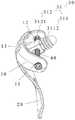
图1示出了根据本实用新型的接骨板组件的实施例的立体结构示意图;Fig. 1 shows a three-dimensional schematic diagram of an embodiment of a bone plate assembly according to the present invention;
图2示出了图1的接骨板组件的侧视示意图;Figure 2 shows a schematic side view of the bone plate assembly of Figure 1;
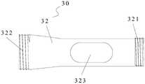
图3示出了图1的接骨板组件的第一弧形板体和第二弧形板体的立体结构示意图;FIG. 3 shows a schematic three-dimensional structure diagram of the first arc-shaped plate body and the second arc-shaped plate body of the bone plate assembly of FIG. 1;
图4示出了图1的接骨板组件的填充固定件的结构示意图;Fig. 4 shows a schematic structural diagram of the filling and fixing member of the bone plate assembly of Fig. 1;
图5示出了图4的填充固定件的局部结构剖视图;Figure 5 shows a partial structural cross-sectional view of the filling fixture of Figure 4;
图6示出了图4的填充固定件的膨胀销的结构示意图。FIG. 6 shows a schematic structural diagram of the expansion pin of the filling fixture of FIG. 4 .
其中,上述附图包括以下附图标记:Wherein, the above-mentioned drawings include the following reference signs:
10、第一弧形板体;11、第一安装孔;12、第二安装孔;13、第一连接孔;20、第二弧形板体;21、第二螺纹孔;22、第二连接孔;30、填充固定件;31、膨胀件;311、连接部;3111、第一螺纹结构;3112、第一螺纹孔;312、膨胀部;3121、膨胀瓣;3122、第三安装孔;32、膨胀销;321、第二螺纹结构;322、第三螺纹结构;323、第四安装孔;40、连接钉。10. The first arc-shaped plate body; 11. The first mounting hole; 12. The second mounting hole; 13. The first connecting hole; 20. The second arc-shaped plate body; 21. The second threaded hole; connection hole; 30, filling and fixing part; 31, expansion part; 311, connection part; 3111, first threaded structure; 3112, first threaded hole; 312, expansion part; 3121, expansion flap; 3122, third installation hole; 32, expansion pin; 321, second thread structure; 322, third thread structure; 323, fourth mounting hole; 40, connecting nail.
具体实施方式Detailed ways
下面将结合本实用新型实施例中的附图,对本实用新型实施例中的技术方案进行清楚、完整地描述,显然,所描述的实施例仅仅是本实用新型一部分实施例,而不是全部的实施例。以下对至少一个示例性实施例的描述实际上仅仅是说明性的,决不作为对本实用新型及其应用或使用的任何限制。基于本实用新型中的实施例,本领域普通技术人员在没有作出创造性劳动前提下所获得的所有其他实施例,都属于本实用新型保护的范围。The technical solutions in the embodiments of the present utility model will be clearly and completely described below with reference to the accompanying drawings in the embodiments of the present utility model. Obviously, the described embodiments are only a part of the embodiments of the present utility model, rather than all the implementations. example. The following description of at least one exemplary embodiment is merely illustrative in nature and is in no way intended to limit the invention, its application or uses in any way. Based on the embodiments of the present invention, all other embodiments obtained by those of ordinary skill in the art without creative work fall within the protection scope of the present invention.
需要注意的是,这里所使用的术语仅是为了描述具体实施方式,而非意图限制根据本申请的示例性实施方式。如在这里所使用的,除非上下文另外明确指出,否则单数形式也意图包括复数形式,此外,还应当理解的是,当在本说明书中使用术语“包含”和/或“包括”时,其指明存在特征、步骤、操作、器件、组件和/或它们的组合。It should be noted that the terminology used herein is for the purpose of describing specific embodiments only, and is not intended to limit the exemplary embodiments according to the present application. As used herein, unless the context clearly dictates otherwise, the singular is intended to include the plural as well, furthermore, it is to be understood that when the terms "comprising" and/or "including" are used in this specification, it indicates that There are features, steps, operations, devices, components and/or combinations thereof.
除非另外具体说明,否则在这些实施例中阐述的部件和步骤的相对布置、数字表达式和数值不限制本实用新型的范围。同时,应当明白,为了便于描述,附图中所示出的各个部分的尺寸并不是按照实际的比例关系绘制的。对于相关领域普通技术人员已知的技术、方法和设备可能不作详细讨论,但在适当情况下,所述技术、方法和设备应当被视为授权说明书的一部分。在这里示出和讨论的所有示例中,任何具体值应被解释为仅仅是示例性的,而不是作为限制。因此,示例性实施例的其它示例可以具有不同的值。应注意到:相似的标号和字母在下面的附图中表示类似项,因此,一旦某一项在一个附图中被定义,则在随后的附图中不需要对其进行进一步讨论。The relative arrangement of the components and steps, the numerical expressions and numerical values set forth in these embodiments do not limit the scope of the invention unless specifically stated otherwise. Meanwhile, it should be understood that, for the convenience of description, the dimensions of various parts shown in the accompanying drawings are not drawn in an actual proportional relationship. Techniques, methods, and devices known to those of ordinary skill in the relevant art may not be discussed in detail, but where appropriate, such techniques, methods, and devices should be considered part of the authorized description. In all examples shown and discussed herein, any specific value should be construed as illustrative only and not as limiting. Accordingly, other examples of exemplary embodiments may have different values. It should be noted that like numerals and letters refer to like items in the following figures, so once an item is defined in one figure, it does not require further discussion in subsequent figures.
为了提高接骨板组件植入后的固定效果,如图1、图2以及图4所示,在本实施例中,接骨板组件,与骨结构配合,接骨板组件包括:第一弧形板体10、第二弧形板体20以及填充固定件30。第一弧形板体10向远离骨结构的方向凸出。第二弧形板体20与第一弧形板体10连接,第二弧形板体20朝向骨结构的方向凸出,其中,第二弧形板体20连接于第一弧形板体10的一个侧边的中点处。填充固定件30与第一弧形板体10和/或第二弧形板体20连接。In order to improve the fixation effect of the bone plate assembly after implantation, as shown in FIG. 1 , FIG. 2 and FIG. 4 , in this embodiment, the bone plate assembly cooperates with the bone structure, and the bone plate assembly includes: a first arc-shaped
应用本实施例的技术方案,第一弧形板体10朝向远离骨结构的方向凸出,第二弧形板体20和第一弧形板体10连接,并朝向骨结构的方向凸出。第二弧形板体20与第一弧形板体10的侧边的中点处连接。填充固定件30与第一弧形板体10和第二弧形板体20连接。通过上述的设置,填充固定件30能够提高第一弧形板体10和第二弧形板体20的固定效果,具体地,将填充固定件30连接在整骨上,再将第一弧形板体10和第二弧形板体20连接在填充固定件30上,这样使得第一弧形板体10和第二弧形板体20能够有效地对骨块碎片进行固定;同时由于第一弧形板体10和第二弧形板体20均为弧形,这样使得第一弧形板体10和第二弧形板体20能够有效地与骨结构进行配合,以实现对骨结构的包裹作用和支撑作用,这样能够进一步地提高接骨板组件的整体的固定效果,并能够保证骨块碎片与整骨的接触较好,进而使得愈合效果较好。因此本实施例的技术方案有效地解决了相关技术中的骨块碎片固定到整体骨上时固定效果较差的问题。Applying the technical solution of this embodiment, the first arc-shaped
需要说明的是,本实施例的第一弧形板体10为C型环抱弧状解剖结构,弧度为140°-170°,优选约为150°,半径约为21mm。能够进行骨贴合,实现更好的骨整合效果,其包括接骨板板身、前外侧翼固定板、后外侧翼固定板三部分。前侧翼固定板贴合胫骨平台前外侧骨面。宽约12mm,厚约2.5mm,其上设置有第一安装孔11,第一安装孔11距离板体边缘距离为5-10mm。优选的8mm。后外侧翼固定板贴合后侧骨面,宽约10mm,厚约2.5mm,其上设置有第二安装孔12,第二安装孔12距离板体边缘距离为5-10mm,优选8mm。第一安装孔11和第二安装孔12的轴线方向一致,同一螺钉可以同时穿过两孔与填充固定件30上的第三安装孔3122和第四安装孔323进行固定、限位。此外,在接骨板前、后外侧固定板之间。设计了6个万向锁定螺钉孔位(即第一连接孔13)。其螺钉轴线与弧形接骨板圆心线的夹角为6°-30°。两孔左右间距约为7.5mm。螺钉的锁定方向可在上、下、左、右360围绕轴线实现10°范围的螺纹锁定,有一定的可调节性。板身(第二弧形板体20)顶端为有负角的尖头,可沿骨面顺利插入。对第一弧形板体10、第二弧形板体20、填充固定件30、塌陷骨、健康骨之间的更加稳定和牢固,不宜发生复位丢失等情况。It should be noted that the first arc-shaped
为了提高第一弧形板体和第二弧形板体的稳定性,如图1至图3所示,在本实施例中,填充固定件30与第一弧形板体10和第二弧形板体20均连接,填充固定件30包括膨胀件31和安装于膨胀件31内的膨胀销32,膨胀件31和第一弧形板体10可拆卸地连接,膨胀销32和第二弧形板体20可拆卸地连接并能够驱动膨胀件31膨胀。填充固定件30和第一弧形板体10和第二弧形板体20均连接,这样使得填充固定件30对第一弧形板体10和第二弧形板体20的连接更加稳定。膨胀件31能够在膨胀销32的作用下进行膨胀,进而实现与骨结构进行固定。具体地,在本实施例中,先通过第一螺纹结构3111将膨胀件31植入骨结构中,再将第二弧形板体20通过膨胀销32连接在膨胀件31上,最后通过连接结构将膨胀件31和第一弧形板体10连接,这样则实现了接骨板组件的固定。In order to improve the stability of the first arc-shaped plate body and the second arc-shaped plate body, as shown in Figs. The shaped
考虑到填充固定件的固定效果,如图1和图2以及图4至图6所示,在本实施例中,膨胀件31包括连接部311以及与连接部311连接的膨胀部312,连接部311的外壁上设置有第一螺纹结构3111,第一螺纹结构3111与骨结构连接,膨胀部312包括多个间隔设置的膨胀瓣3121,膨胀销32位于膨胀部312的内部,膨胀销32能够推顶膨胀部312以使相邻的膨胀瓣3121之间的距离增大。上述的膨胀瓣3121能够被撑开,以使其与骨结构的接触更加紧密,进而提高了膨胀件与骨结构的连接强度。Considering the fixing effect of the filling and fixing member, as shown in FIGS. 1 and 2 and FIGS. 4 to 6 , in this embodiment, the
如图1和图2以及图4至图6所示,在本实施例中,膨胀部312的外表面设置有微孔结构层。微孔结构层能够更好地与骨结构接触,进而使得骨结构能够长入至微孔结构层内,以实现生物固定,这样的固定方式更加简单高效,同时固定效果更好。微孔结构层为3D打印便于骨细胞长入的微孔结构该微孔结构是一种相互连通的多向微孔隙结构,厚度约为2mm,孔隙直径为800μm,该孔隙有利于骨细胞爬行长入,术后可融合骨骼面将与生理骨结构发生骨融合以达到长期稳定。As shown in FIGS. 1 and 2 and FIGS. 4 to 6 , in this embodiment, the outer surface of the
在图中未示出的实施例中,向膨胀件的内部灌入骨水泥,在膨胀销推顶膨胀瓣的同时将骨水泥从膨胀瓣的间隙处顶出,这样也能够有效地实现固定。In the embodiment not shown in the figure, bone cement is poured into the expansion member, and the bone cement is pushed out from the gap of the expansion flap while the expansion pin pushes the expansion flap, which can also effectively achieve fixation.
为了便于膨胀销的连接以及膨胀销能够更好地支撑膨胀件,如图1和图2以及图4至图6所示,在本实施例中,连接部311的内部设置有第一螺纹孔3112,膨胀销32的第一端设置有第二螺纹结构321,第二螺纹结构321和第一螺纹孔3112螺接配合,在膨胀销32第一端至第二端的方向上,膨胀销32的直径逐渐增大。由于膨胀销32第一端至第二端的方向上直径逐渐增大,这样使得在将膨胀销32旋转至膨胀件31内时,膨胀销32的第一端位于膨胀件31内,膨胀销32的第二端位于膨胀件31外,进而膨胀销32的第二端能够推顶膨胀瓣3121进而使得膨胀瓣3121撑开。In order to facilitate the connection of the expansion pin and the expansion pin to better support the expansion piece, as shown in FIGS. 1 and 2 and FIGS. 4 to 6 , in this embodiment, a first threaded
在图中未示出的实施例中,膨胀销先植入至骨结构上,再通过膨胀件连接至膨胀销上,这样也能够有效地实现固定。In the embodiment not shown in the figure, the expansion pin is first implanted on the bone structure, and then connected to the expansion pin through the expansion piece, which can also effectively achieve fixation.
如图1和图2以及图4至图6所示,在本实施例中,膨胀销32的第二端设置有第三螺纹结构322,第二弧形板体20上设置有第二螺纹孔21,第三螺纹结构322和第二螺纹孔21螺接配合。上述的设置能够有效地实现膨胀销32和第二弧形板体20的固定。As shown in FIGS. 1 and 2 and FIGS. 4 to 6 , in this embodiment, the second end of the
如图1和图2以及图4至图6所示,在本实施例中,第一弧形板体10的第一端设置有第一安装孔11,第一弧形板体10的第二端设置有第二安装孔12,膨胀部312上设置有第三安装孔3122,膨胀销32上设置有第四安装孔323,第一安装孔11和第二安装孔12对应设置,第一安装孔11和第二安装孔12的轴线同线并垂直于膨胀部312的长度方向,第三安装孔3122和第四安装孔323对应设置,接骨板组件还包括连接钉40,连接钉40依次穿过第一安装孔11、第三安装孔3122、第四安装孔323以及第二安装孔12。上述的连接钉40能够将填充固定件30有效地固定在第一弧形板体10上,这样的设置方式较为简单。同时,上述的设置方式使得填充固定件30相对于第一弧形板体10可摆动地设置,这样能够调节其与骨结构的连接位置,这样能够提高连接的效果。As shown in FIGS. 1 and 2 and FIGS. 4 to 6 , in this embodiment, a first mounting
如图1和图2以及图4至图6所示,在本实施例中,第四安装孔323的长度大于第三安装孔3122的长度。上述的设置能够保证连接钉40能够准确地穿过第四安装孔323。As shown in FIGS. 1 and 2 and FIGS. 4 to 6 , in this embodiment, the length of the fourth mounting
为了进一步地提高第一弧形板体和第二弧形板体的连接效果,如图1至图3所示,在本实施例中,第一弧形板体10上还设置有多个第一连接孔13,多个第一连接孔13阵列排布,并位于第一弧形板体10的中部,第二弧形板体20上设置有多个第二连接孔22。上述的多个第一连接孔13和多个第二连接孔22的设置是为了进一步提高连接的效果,具体地,在本实施例中,紧固件穿过多个第一连接孔13和多个第二连接孔22与骨结构连接。In order to further improve the connection effect between the first arc-shaped plate body and the second arc-shaped plate body, as shown in FIG. 1 to FIG. 3 , in this embodiment, the first arc-shaped
当然,在图中未示出的实施例中,还可以将骨水泥灌注在多个第一连接孔和多个第二连接孔内,以实现固定。Of course, in the embodiment not shown in the figures, bone cement can also be poured into the plurality of first connection holes and the plurality of second connection holes to achieve fixation.
如图1至图3所示,在本实施例中,第二弧形板体20远离第一弧形板体10的一端与第一弧形板体10的两端之间的距离相等。上述的设置使得第一弧形板体10和第二弧形板体20之间相对垂直,并位于平分线的位置上,这样的设置使得第一弧形板体10和第二弧形板体20能够更好地与骨结构接触。As shown in FIGS. 1 to 3 , in this embodiment, the distance between one end of the second arc-shaped
如图1至图6所示,本实施例的接骨板组件有效地实现了万向的锁定胫骨近端外侧的固定。接骨板组件由第一弧形板体10、第二弧形板体20配以填充固定件30进行骨折的复位、固定。第一弧形板体10包括解剖型环抱结构及前后两侧翼固定板,两侧翼固定板远侧设置有第一安装孔11和及第二安装孔12,可使用连接钉40穿过第一安装孔11和及第二安装孔12与填充固定件30进行限位、固定;填充固定件30由钛合金材料经3D打印制成,其前端为第一螺纹结构3111,可稳定的与健康骨结构进行固定,后端为可膨胀部、表面为经3D打印的微孔结构层,可配合膨胀销32对塌陷骨块稳定固定在整体骨上,表面微孔设计可促进骨生长,增加骨折、塌陷骨块和整体骨的稳定性,且填充固定件30上的第三安装孔3122和第四安装孔323可通过连接钉40连接,膨胀销32尾端为第三螺纹结构322。可以锁定于第二弧形板体20上。使第一弧形板体10、第二弧形板体20以及填充固定件30与生理骨之间的固定更加稳定,术后恢复锻炼时不宜造成复位丢失。As shown in FIGS. 1 to 6 , the bone plate assembly of this embodiment effectively achieves universal locking of the outer side of the proximal tibia. The bone plate assembly is composed of a first arc-shaped
本实施例的接骨板组件在手术操作过程中,行外侧手术切开,保护重要血管神经,显露骨折部位,进行关节复位,清理手术部位,确定手术中所需胫骨平台外侧接骨板及螺钉的规格和数量,实施植入手术,植入填充固定件30、第一弧形板体10以及第二弧形板体20固定到手术要求位置,实现手术目的。During the operation of the bone plate assembly of this embodiment, a lateral surgical incision is performed to protect important blood vessels and nerves, expose the fracture site, perform joint reduction, clean the operation site, and determine the specifications of the lateral bone plate and screws of the tibial plateau required during the operation. and quantity, the implantation operation is performed, and the implant filling and fixing
本实施例的第一弧形板体10和第二弧形板体20采用医用金属制成,所述医用金属包括但不局限于钛及钛合金、钴合金、不锈钢以及钽金属、镁合金,此类金属材料在ISO-5830系列国际标准中均有规定,其生物相容性已经得到国内外多年骨科植入应用的实践证实。The first arc-shaped
在本实用新型的描述中,需要理解的是,方位词如“前、后、上、下、左、右”、“横向、竖向、垂直、水平”和“顶、底”等所指示的方位或位置关系通常是基于附图所示的方位或位置关系,仅是为了便于描述本实用新型和简化描述,在未作相反说明的情况下,这些方位词并不指示和暗示所指的装置或元件必须具有特定的方位或者以特定的方位构造和操作,因此不能理解为对本实用新型保护范围的限制;方位词“内、外”是指相对于各部件本身的轮廓的内外。In the description of the present invention, it should be understood that orientation words such as "front, rear, top, bottom, left, right", "horizontal, vertical, vertical, horizontal" and "top, bottom" etc. The orientation or positional relationship is usually based on the orientation or positional relationship shown in the accompanying drawings, which is only for the convenience of describing the present invention and simplifying the description, and these orientations do not indicate and imply the indicated device unless otherwise stated. Or elements must have a specific orientation or be constructed and operated in a specific orientation, so it cannot be construed as a limitation on the protection scope of the present invention; the orientation words "inside and outside" refer to the inside and outside relative to the contour of each component itself.
为了便于描述,在这里可以使用空间相对术语,如“在……之上”、“在……上方”、“在……上表面”、“上面的”等,用来描述如在图中所示的一个器件或特征与其他器件或特征的空间位置关系。应当理解的是,空间相对术语旨在包含除了器件在图中所描述的方位之外的在使用或操作中的不同方位。例如,如果附图中的器件被倒置,则描述为“在其他器件或构造上方”或“在其他器件或构造之上”的器件之后将被定位为“在其他器件或构造下方”或“在其他器件或构造之下”。因而,示例性术语“在……上方”可以包括“在……上方”和“在……下方”两种方位。该器件也可以其他不同方式定位(旋转90度或处于其他方位),并且对这里所使用的空间相对描述作出相应解释。For ease of description, spatially relative terms, such as "on", "over", "on the surface", "above", etc., may be used herein to describe what is shown in the figures. The spatial positional relationship of one device or feature shown to other devices or features. It should be understood that spatially relative terms are intended to encompass different orientations of the device in use or operation in addition to the orientation depicted in the figures. For example, if the device in the figures is turned over, elements described as "above" or "over" other devices or features would then be oriented "below" or "over" the other devices or features under other devices or constructions". Thus, the exemplary term "above" can encompass both an orientation of "above" and "below." The device may also be otherwise oriented (rotated 90 degrees or at other orientations) and the spatially relative descriptions used herein interpreted accordingly.
此外,需要说明的是,使用“第一”、“第二”等词语来限定零部件,仅仅是为了便于对相应零部件进行区别,如没有另行声明,上述词语并没有特殊含义,因此不能理解为对本实用新型保护范围的限制。In addition, it should be noted that the use of words such as "first" and "second" to define components is only for the convenience of distinguishing corresponding components. Unless otherwise stated, the above words have no special meaning and therefore cannot be understood To limit the scope of protection of the present invention.
以上所述仅为本实用新型的优选实施例而已,并不用于限制本实用新型,对于本领域的技术人员来说,本实用新型可以有各种更改和变化。凡在本实用新型的精神和原则之内,所作的任何修改、等同替换、改进等,均应包含在本实用新型的保护范围之内。The above descriptions are only preferred embodiments of the present utility model, and are not intended to limit the present utility model. For those skilled in the art, the present utility model may have various modifications and changes. Any modification, equivalent replacement, improvement, etc. made within the spirit and principle of the present invention shall be included in the protection scope of the present invention.
Claims (10)
Priority Applications (1)
| Application Number | Priority Date | Filing Date | Title |
|---|---|---|---|
| CN202122689888.2UCN216754579U (en) | 2021-11-04 | 2021-11-04 | Bone plate assembly |
Applications Claiming Priority (1)
| Application Number | Priority Date | Filing Date | Title |
|---|---|---|---|
| CN202122689888.2UCN216754579U (en) | 2021-11-04 | 2021-11-04 | Bone plate assembly |
Publications (1)
| Publication Number | Publication Date |
|---|---|
| CN216754579Utrue CN216754579U (en) | 2022-06-17 |
Family
ID=81960226
Family Applications (1)
| Application Number | Title | Priority Date | Filing Date |
|---|---|---|---|
| CN202122689888.2UWithdrawn - After IssueCN216754579U (en) | 2021-11-04 | 2021-11-04 | Bone plate assembly |
Country Status (1)
| Country | Link |
|---|---|
| CN (1) | CN216754579U (en) |
Cited By (2)
| Publication number | Priority date | Publication date | Assignee | Title |
|---|---|---|---|---|
| CN113925590A (en)* | 2021-11-04 | 2022-01-14 | 北京理贝尔生物工程研究所有限公司 | Bone plate assembly |
| CN119279740A (en)* | 2024-10-16 | 2025-01-10 | 广东健齿生物科技有限公司 | Wire-fixed bone plate |
- 2021
- 2021-11-04CNCN202122689888.2Upatent/CN216754579U/ennot_activeWithdrawn - After Issue
Cited By (4)
| Publication number | Priority date | Publication date | Assignee | Title |
|---|---|---|---|---|
| CN113925590A (en)* | 2021-11-04 | 2022-01-14 | 北京理贝尔生物工程研究所有限公司 | Bone plate assembly |
| CN113925590B (en)* | 2021-11-04 | 2025-08-08 | 北京理贝尔生物工程研究所有限公司 | Bone plate components |
| CN119279740A (en)* | 2024-10-16 | 2025-01-10 | 广东健齿生物科技有限公司 | Wire-fixed bone plate |
| CN119279740B (en)* | 2024-10-16 | 2025-07-25 | 广东健齿生物科技有限公司 | Binding wire type bone fracture plate |
Similar Documents
| Publication | Publication Date | Title |
|---|---|---|
| CN103876865B (en) | Inflatable Invasive lumbar fusion device | |
| CN216754579U (en) | Bone plate assembly | |
| CN107411855A (en) | Atlas and axis fusion of intervertebral joints device | |
| CN107496061B (en) | A modular artificial sacral prosthesis | |
| CN203089338U (en) | Atlantoaxial anterior approach restoration inner fixing device | |
| CN203089337U (en) | Minitype internal fixation and fusion device of atlantoaxial lateral mass joint | |
| CN103445835A (en) | Hip joint correction and thighbone extender | |
| CN203677225U (en) | External fixing device for emergency treatment recovery of limb long-pipe-bone | |
| CN103637839B (en) | Rapid restorer for treating fracture of long tubular bones of limbs | |
| US20210038261A1 (en) | Implants and methods for treating charcot foot and other conditions | |
| CN211485099U (en) | Backbone prosthesis of post-screwing type tube expanding structure handle | |
| CN102178557B (en) | Pelvic internal fixation unit and application thereof | |
| CN211156481U (en) | Acetabular prosthesis | |
| CN113925590B (en) | Bone plate components | |
| CN108403265A (en) | A kind of upper cervical spine artificial vertebral body support device | |
| CN216495884U (en) | Vertebral body prosthesis | |
| CN116763509A (en) | Knee joint tibia prosthesis | |
| CN209285836U (en) | Osteotomy Orthopedic Fusion Device | |
| CN211512016U (en) | Screw for supporting vertebral body | |
| CN205007076U (en) | Artificial vertebral lamina | |
| CN211985641U (en) | Bone nail imbedding device | |
| CN209285839U (en) | Waist sacrum artificial prosthesis | |
| CN203425016U (en) | Hip joint orthopedics and thigh bone extender | |
| CN209790100U (en) | novel full sacrum prosthesis | |
| CN209285844U (en) | Artificial axis |
Legal Events
| Date | Code | Title | Description |
|---|---|---|---|
| GR01 | Patent grant | ||
| GR01 | Patent grant | ||
| AV01 | Patent right actively abandoned | ||
| AV01 | Patent right actively abandoned | ||
| AV01 | Patent right actively abandoned | Granted publication date:20220617 Effective date of abandoning:20250808 | |
| AV01 | Patent right actively abandoned | Granted publication date:20220617 Effective date of abandoning:20250808 |