CN216754441U - Gap detector combining straightening gap and buckling gap - Google Patents
Gap detector combining straightening gap and buckling gapDownload PDFInfo
- Publication number
- CN216754441U CN216754441UCN202122451184.1UCN202122451184UCN216754441UCN 216754441 UCN216754441 UCN 216754441UCN 202122451184 UCN202122451184 UCN 202122451184UCN 216754441 UCN216754441 UCN 216754441U
- Authority
- CN
- China
- Prior art keywords
- gap
- plate
- straightening
- posterior condyle
- detector
- Prior art date
- Legal status (The legal status is an assumption and is not a legal conclusion. Google has not performed a legal analysis and makes no representation as to the accuracy of the status listed.)
- Active
Links
Images


Landscapes
- Prostheses (AREA)
Abstract
Description
Translated fromChinese技术领域technical field
本实用新型涉及一种伸直间隙、屈曲间隙相结合的间隙检测器,属于医疗设备技术领域。The utility model relates to a gap detector combining a straightening gap and a flexing gap, belonging to the technical field of medical equipment.
背景技术Background technique
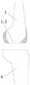
目前,随着人口老龄化的出现,罹患膝关节骨关节的患者越来越多,其使得患者出现膝关节酸痛,无法站立,或者行走不稳等症状,而膝关节表面置换是治疗膝关节骨关节炎的最终手段,需要医生将胫骨4与股骨1的那些坏死或磨损的关节面进行切除并安装人工关节假体2,如图1所示,使得患者能够重新站立以及正常走路。At present, with the aging of the population, more and more patients suffer from knee osteoarthritis, which makes patients suffer from knee joint pain, inability to stand, or unstable walking. Knee joint resurfacing is a treatment for knee joint osteoarthritis The last resort of arthritis requires a doctor to remove those necrotic or worn articular surfaces of the
在膝关节骨表面置换手术操作时,伸直间隙、屈曲间隙的平衡是手术操作的关键,伸直间隙优先是截骨操作的最常用的有效方法。目前骨科医师的操作是:先以定位器切去股骨1远端(图3中的第一切面1-3),然后再截取胫骨4近端,在股骨1远端和胫骨4近端之间形成伸直间隙。通过前参照或者后参照测量器,参照经验决定屈曲间隙的大小和内外旋转,然后按照股骨截骨板,截取图3中股骨1的第二切面1-5、第三切面1-4、第四切面1-2、第五切面1-1。切骨完成后将人工关节假体2套在股骨1的切面上。In knee resurfacing surgery, the balance of extension gap and flexion gap is the key to the operation, and the priority of extension gap is the most commonly used and effective method for osteotomy. The current orthopaedic surgeon's operation is to cut off the distal end of femur 1 (the first section 1-3 in Fig. 3 ) with a locator, and then cut off the proximal end of
上述手术操作存在以下问题:The above surgical operation has the following problems:
伸直间隙确定后,使用现有的前参照或者后参照测量器,在决定屈曲间隙时,医生是靠其肉眼观察并通过自身的经验来确定第二切面1-5的位置,由于屈曲股骨1的下面没有定位的装置,且不同人膝关节骨上股骨1与胫骨4两侧之间的间隙不同,因此,无法保证第二切面1-5截取前,屈曲股骨1两侧与胫骨4之间相平衡,无法获得一个与伸直间隙相等的屈曲间隙,而且屈曲间隙自身内侧和外侧不能精确平衡,从而使得股骨截骨板的定位位置并不精确,影响手术后工关节假体的安装,以及安装后可能使得病患无法站立或坐下的问题,影响术后的康复。After the extension gap is determined, the existing anterior reference or posterior reference measuring instrument is used. When determining the flexion gap, the doctor determines the position of the second plane 1-5 by visual observation and his own experience. There is no positioning device below the knee joint, and the gap between the two sides of the
发明内容SUMMARY OF THE INVENTION
本实用新型要解决的技术问题是:如何保证截骨器的定位精确度。The technical problem to be solved by the utility model is: how to ensure the positioning accuracy of the osteotomy device.
为了解决上述技术问题,本实用新型的技术方案是提供了一种伸直间隙、屈曲间隙相结合的间隙检测器,其特征在于,包括伸直间隙板,伸直间隙板与手柄固定连接,伸直间隙板的底部设有后髁板,后髁板的一侧与伸直间隙板固定连接,后髁板另一侧表面设有与屈曲股骨相匹配的弧形结构,后髁板的底部设有用于安装补充板的安装结构。In order to solve the above-mentioned technical problems, the technical solution of the present utility model is to provide a gap detector combining the straightening gap and the flexing gap, which is characterized in that it includes a straightening gap plate, and the straightening gap plate is fixedly connected with the handle, and the straightening gap plate is fixedly connected with the handle. The bottom of the straight gap plate is provided with a posterior condyle plate, one side of the posterior condyle plate is fixedly connected with the straightening gap plate, the other side surface of the posterior condyle plate is provided with an arc-shaped structure that matches the flexed femur, and the bottom of the posterior condyle plate is provided with an arc structure. There are mounting structures for mounting supplementary boards.
优选地,所述的后髁板的一侧设于伸直间隙板的正下方,后髁板另一侧的弧形结构设于伸直间隙板的外侧。Preferably, one side of the posterior condyle plate is disposed directly below the straightening gap plate, and the arc structure on the other side of the posterior condyle plate is disposed outside the straightening gap plate.
优选地,所述的后髁板的弧形结构与伸直间隙板的一端形成台阶状结构;伸直间隙板高度大于后髁板弧形结构的高度。Preferably, the arc structure of the posterior condyle plate and one end of the straightening gap plate form a stepped structure; the straightening gap plate height is greater than the height of the arcuate structure of the posterior condyle plate.
优选地,所述的伸直间隙板的上表面为水平面。Preferably, the upper surface of the straightening gap plate is a horizontal plane.
优选地,所述的后髁板上弧形结构的端部设有凹槽,用于避开胫骨与股骨之间连接的筋。Preferably, the end of the arc-shaped structure on the posterior condyle plate is provided with a groove for avoiding the tendon connecting the tibia and the femur.
优选地,所述的手柄上设有孔,孔的开孔方向与伸直间隙板垂直。Preferably, the handle is provided with a hole, and the opening direction of the hole is perpendicular to the straightening gap plate.
优选地,所述的孔的数量至少为两个。Preferably, the number of the holes is at least two.
优选地,所述的安装结构包括安装槽和凸起,每个补充板的上表面均设有凸起,每个补充板的下表面与凸起相对的位置均设有与凸起相匹配的安装槽,后髁板的底部与其连接的补充板上凸起相对的位置设有安装槽。Preferably, the installation structure includes installation grooves and protrusions, the upper surface of each supplementary plate is provided with protrusions, and the positions opposite to the protrusions on the lower surface of each supplementary plate are provided with matching protrusions. An installation groove is provided on the bottom of the posterior condyle plate at the position opposite to the protrusion on the supplementary plate to which it is connected.
优选地,所述的伸直间隙板和手柄为一体成型结构;伸直间隙板与后髁板为一体成型结构,或伸直间隙板与后髁板通过紧固件固定在一起,或在伸直间隙板与后髁板通过凸起和安装槽直接卡接在一起。Preferably, the straightening gap plate and the handle are integrally formed; the straightening gap plate and the posterior condyle plate are integrally formed; The straight gap plate and the posterior condyle plate are directly clamped together through protrusions and installation grooves.
本实用新型的间隙检测器在现有的基础上增加了后髁板,使得间隙检测器能更加贴合的卡在胫骨与股骨之间的间隙内,伸直间隙与通过截骨器得到的屈曲间隙相对应,避免股骨的晃动,提高了股骨切除的精确度;同时通过增加不同数量的补充板,能更好的使得检测器卡在间隙内。The gap detector of the utility model adds a posterior condyle plate on the existing basis, so that the gap detector can be stuck in the gap between the tibia and the femur more closely, and the extension gap is related to the flexion obtained by the osteotomy device. The gaps correspond to avoid the shaking of the femur and improve the accuracy of the femoral resection; at the same time, by adding different numbers of supplementary plates, the detector can be better stuck in the gap.
本实用新型用于在膝关节表面置换术中,基于伸直间隙截骨完成的基础上,通过本实用新型的检测器,于屈曲间隙截骨时,辅助伸直、屈曲间隙平衡的检测,达到屈曲间隙截骨的同时完成伸直、屈曲间隙的平衡。The utility model is used in knee joint surface replacement surgery, based on the completion of the extension gap osteotomy, through the detector of the utility model, when the flexion gap osteotomy is performed, the detection of the balance of extension and flexion gap is assisted, so as to achieve The balance of extension and flexion gap is completed at the same time as flexion gap osteotomy.
附图说明Description of drawings
图1为膝关节骨表面置换人工关节假体后的示意图;Fig. 1 is the schematic diagram after knee joint bone surface replacement artificial joint prosthesis;
图2为伸直的股骨底部横向截去一个截面、横向截去胫骨上的关节面后形成伸直间隙的示意图;Fig. 2 is a schematic diagram of forming a straightening gap after transversely cutting off a section of the bottom of the straightened femur and transversely cutting off the articular surface on the tibia;
图3为股骨切除后的示意图;Fig. 3 is the schematic diagram after femur resection;
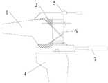
图4为一种伸直间隙、屈曲间隙相结合的间隙检测器的立体图;4 is a perspective view of a gap detector combining a straightening gap and a flexing gap;
图5为一种伸直间隙、屈曲间隙相结合的间隙检测器的侧视图;FIG. 5 is a side view of a gap detector combining a straightening gap and a flexing gap;
图6为一种伸直间隙、屈曲间隙相结合的间隙检测器伸入伸直间隙内的示意图;6 is a schematic diagram of a gap detector combined with a straightening gap and a flexing gap extending into the straightening gap;
图7为一种伸直间隙、屈曲间隙相结合的间隙检测器的使用示意图。FIG. 7 is a schematic diagram of the use of a gap detector combining extension gap and flexion gap.
具体实施方式Detailed ways
为使本实用新型更明显易懂,兹以优选实施例,并配合附图作详细说明如下。In order to make the present utility model more obvious and easy to understand, preferred embodiments are described below in detail with the accompanying drawings.
如图2-图7所示,使用本实用新型的检测器7,膝关节骨表面置换手术的整体操作步骤如下:As shown in Figures 2-7, using the
骨科医生在给患者进行截骨手术时,先在股骨1底部截去股骨远端,形成第一切面1-3,如图2所示。然后在水平面截去胫骨4近端的关节面3,完成伸直间隙截骨,伸直间隙为股骨1伸直时与截去近端关节3的胫骨4之间的距离,然后通过检测器7对伸直间隙进行测量检测,使得检测器7松紧合适地卡在伸直间隙内,调整膝关节平衡;随后将膝关节屈曲,并通过将检测器7放置在截去关节面3的胫骨4上,检测器7的前侧顶在屈曲股骨1上与第一切面1-3同侧的侧面,然后将截骨器放置在检测器7上定位,沿着检测器7的顶部通过截骨器水平截去屈曲的股骨1底部的一个截面(即图3中的第二切面1-5),使得伸直间隙和屈曲间隙相同,屈曲间隙是股骨1屈曲时与截去关节面3的胫骨4之间的距离。然后根据股骨以及人工关节假体的大小,并通过间隙测量器得到最接近股骨尺寸的人工关节假体2的数据,最后通过截骨器依次进行股骨1上第三切面1-4、第四切面1-2、第五切面1-1的切除,如图3所示,其中,第五切面1-1的高度决定人工关节假体2的大小。切骨完成后将人工关节假体2套在股骨1的切面上。When an orthopedic surgeon performs an osteotomy on a patient, the distal end of the femur is first cut off at the bottom of the
本实用新型提供了一种伸直间隙、屈曲间隙相结合的间隙检测器(即检测器7),如图4、图5所示,其包括伸直间隙板7-6,伸直间隙板7-6的上表面为水平面,伸直间隙板7-6与手柄7-1固定连接,伸直间隙板7-6的底部设有后髁板7-2,后髁板7-2的一侧与伸直间隙板7-6固定连接,后髁板7-2另一侧表面设有与屈曲股骨相匹配的弧形结构,后髁板7-2的一侧设于伸直间隙板7-6的正下方,后髁板7-2另一侧的弧形结构设于伸直间隙板7-6的外侧,后髁板7-2作为伸直间隙板7-6的过渡板以及延伸板,后髁板7-2的弧形结构与伸直间隙板7-6的一端形成台阶状结构,即伸直间隙板7-6一端的高度大于后髁板7-2弧形结构的高度。后髁板7-2另一侧的端部设有凹槽7-7,用于避开胫骨4与股骨1之间连接的筋。手柄7-1上设有孔7-5,孔7-5的开孔方向与伸直间隙板7-6垂直,孔7-5的数量为两个。后髁板7-2的底部设有用于安装补充板7-3的安装结构,根据需要,增加一定数量的补充板7-3,从而增加整个检测器的高度。安装结构包括安装槽7-4和凸起7-8,每个补充板7-3的上表面均设有凸起7-8,每个补充板7-3的下表面与凸起7-8相对的位置均设有与凸起7-8相匹配的安装槽7-4,后髁板7-2的底部与其连接的补充板7-3上凸起7-8相对的位置也设有安装槽7-4。The utility model provides a gap detector (ie, detector 7) that combines the straightening gap and the flexing gap, as shown in Figure 4 and Figure 5, which includes straightening gap plates 7-6,
其中,伸直间隙板7-6和手柄7-1为一体成型结构,伸直间隙板7-6与后髁板7-2可以是一体成型结构,也可以是通过紧固件固定在一起,或者伸直间隙板7-6与后髁板7-2通过凸起7-8和安装槽7-4直接卡接在一起。Wherein, the straightening gap plate 7-6 and the handle 7-1 are integrally formed, and the straightening gap plate 7-6 and the posterior condyle plate 7-2 can be an integrally formed structure, or can be fixed together by fasteners, Alternatively, the straightening gap plate 7-6 and the posterior condyle plate 7-2 are directly clamped together through the protrusion 7-8 and the installation groove 7-4.
如图4-图7所示,本实用新型的使用过程如下:As shown in Figure 4-Figure 7, the use process of the present utility model is as follows:
在基于伸直间隙截骨完成的基础上,使用本实用新型的检测器7进行伸直间隙的测量,将检测器7放置在伸直间隙内,如果伸直间隙板7-6位置处的高度不够,即伸直间隙板7-6的上侧或下侧与伸直间隙上侧之间存在间隙,那么在后髁板7-2的底部逐渐增加补充板7-3,直至检测器7卡紧在伸直间隙内。On the basis of the completion of the osteotomy based on the straightening gap, the
随后将膝关节弯曲,术者将检测器7放置在截去关节面3的胫骨4上,并手握手柄7-1,将固定在一起的伸直间隙板7-6和后髁板7-2向胫骨4与屈曲股骨1之间的间隙(屈曲间隙)内推进,使得后髁板7-2上的弧形结构正好卡在屈曲股骨1的底部,当后髁板7-2不足以填满胫骨4与屈曲股骨1之间的间隙时,在后髁板7-2的底部不断叠加补充板7-3,直至胫骨4与屈曲股骨1之间没有间隙,即股骨1不能相对后髁板7-2向两侧晃动。再在手柄7-1的孔7-5内插入直杆,确保直杆与股骨1的伸直间隙截骨的切面平行,即判断检测器7是否水平。随后将截骨器6放置在伸直间隙板7-6上,并使得截骨器6贴合在伸直间隙截骨完成后的屈曲的股骨1上(即图3中的第一切面1-3上),根据截骨器6的位置,在屈曲的股骨1端部穿洞,使得截骨器6在股骨1上定位,然后根据股骨1的尺寸,通过测量器5确定水平切屈曲股骨1顶部的刀口位置,随后进行股骨上各个位置的切除操作,使得伸直间隙与通过截骨器得到的屈曲间隙相对应,最后将人工关节假体2套在截骨后的股骨上,即完成膝关节骨表面置换的手术。The knee joint is then flexed, the operator places the
Claims (9)
Translated fromChinesePriority Applications (1)
| Application Number | Priority Date | Filing Date | Title |
|---|---|---|---|
| CN202122451184.1UCN216754441U (en) | 2021-10-12 | 2021-10-12 | Gap detector combining straightening gap and buckling gap |
Applications Claiming Priority (1)
| Application Number | Priority Date | Filing Date | Title |
|---|---|---|---|
| CN202122451184.1UCN216754441U (en) | 2021-10-12 | 2021-10-12 | Gap detector combining straightening gap and buckling gap |
Publications (1)
| Publication Number | Publication Date |
|---|---|
| CN216754441Utrue CN216754441U (en) | 2022-06-17 |
Family
ID=81954681
Family Applications (1)
| Application Number | Title | Priority Date | Filing Date |
|---|---|---|---|
| CN202122451184.1UActiveCN216754441U (en) | 2021-10-12 | 2021-10-12 | Gap detector combining straightening gap and buckling gap |
Country Status (1)
| Country | Link |
|---|---|
| CN (1) | CN216754441U (en) |
- 2021
- 2021-10-12CNCN202122451184.1Upatent/CN216754441U/enactiveActive
Similar Documents
| Publication | Publication Date | Title |
|---|---|---|
| US12274452B2 (en) | Surgical kit for tibial resection and replacement | |
| US11134959B2 (en) | Patient matched instrument | |
| US5702460A (en) | Revision femoral trial prosthesis | |
| US8454616B2 (en) | Method and apparatus for achieving correct limb alignment in unicondylar knee arthroplasty | |
| JP5668213B2 (en) | Resection guide-Resection guide stand structure | |
| Marmor | Unicompartmental and total knee arthroplasty | |
| CN107049415A (en) | Femur distal osteotomy positioning guide device and positioning method thereof | |
| CN110720962B (en) | Osteotomy system for knee joint replacement | |
| CN103491882B (en) | Patient-specific repositioning test blocks | |
| KR20220138389A (en) | Partial knee implant and its installation method | |
| Insall et al. | Total condylar knee replacement: preliminary report | |
| WO2021008892A1 (en) | Method for designing a joint prosthesis | |
| CN115778476A (en) | Complete set of device for adjusting osteotomy on femoral side in knee joint replacement | |
| CN216754441U (en) | Gap detector combining straightening gap and buckling gap | |
| CN113855346B (en) | Knee joint bone surface replacement device | |
| CN115005986B (en) | Individual intelligent navigation positioning device for single condyle replacement surgery and osteotome | |
| CN207168541U (en) | Distal femur osteotomy positioning guide device | |
| CN115153834A (en) | A 3D preoperative intelligent osteotomy and orthopedic method and system for lower limbs | |
| CN216754620U (en) | An adjustable gap detector | |
| CN114053000A (en) | Reference frame for rotational positioning of femoral prostheses | |
| RU2800021C1 (en) | Method of setting rotation of the femoral component and flexion gap in primary and revision knee arthroplasty | |
| CN217696721U (en) | Femoral osteotomy auxiliary tool with linkage of flexion gap and extension gap | |
| CN217488974U (en) | An extension and flexion gap combined measuring device | |
| Kendoff et al. | A navigated 8-in-1 femoral cutting guide for total knee arthroplasty: technical development and cadaveric evaluation | |
| Inkpen | Precision and accuracy in computer-assisted total knee replacement |
Legal Events
| Date | Code | Title | Description |
|---|---|---|---|
| GR01 | Patent grant | ||
| GR01 | Patent grant |