CN216742070U - Pressurized mixed flow generator and portable bladeless fan with same - Google Patents
Pressurized mixed flow generator and portable bladeless fan with sameDownload PDFInfo
- Publication number
- CN216742070U CN216742070UCN202122972208.8UCN202122972208UCN216742070UCN 216742070 UCN216742070 UCN 216742070UCN 202122972208 UCN202122972208 UCN 202122972208UCN 216742070 UCN216742070 UCN 216742070U
- Authority
- CN
- China
- Prior art keywords
- fan
- pressurizing
- mixed flow
- air
- seat
- Prior art date
- Legal status (The legal status is an assumption and is not a legal conclusion. Google has not performed a legal analysis and makes no representation as to the accuracy of the status listed.)
- Active
Links
Images


Classifications
- F—MECHANICAL ENGINEERING; LIGHTING; HEATING; WEAPONS; BLASTING
- F04—POSITIVE - DISPLACEMENT MACHINES FOR LIQUIDS; PUMPS FOR LIQUIDS OR ELASTIC FLUIDS
- F04D—NON-POSITIVE-DISPLACEMENT PUMPS
- F04D25/00—Pumping installations or systems
- F04D25/02—Units comprising pumps and their driving means
- F04D25/08—Units comprising pumps and their driving means the working fluid being air, e.g. for ventilation
- F04D25/084—Units comprising pumps and their driving means the working fluid being air, e.g. for ventilation hand fans
- F—MECHANICAL ENGINEERING; LIGHTING; HEATING; WEAPONS; BLASTING
- F04—POSITIVE - DISPLACEMENT MACHINES FOR LIQUIDS; PUMPS FOR LIQUIDS OR ELASTIC FLUIDS
- F04D—NON-POSITIVE-DISPLACEMENT PUMPS
- F04D25/00—Pumping installations or systems
- F04D25/02—Units comprising pumps and their driving means
- F04D25/08—Units comprising pumps and their driving means the working fluid being air, e.g. for ventilation
- F—MECHANICAL ENGINEERING; LIGHTING; HEATING; WEAPONS; BLASTING
- F04—POSITIVE - DISPLACEMENT MACHINES FOR LIQUIDS; PUMPS FOR LIQUIDS OR ELASTIC FLUIDS
- F04D—NON-POSITIVE-DISPLACEMENT PUMPS
- F04D17/00—Radial-flow pumps, e.g. centrifugal pumps; Helico-centrifugal pumps
- F04D17/06—Helico-centrifugal pumps
- F—MECHANICAL ENGINEERING; LIGHTING; HEATING; WEAPONS; BLASTING
- F04—POSITIVE - DISPLACEMENT MACHINES FOR LIQUIDS; PUMPS FOR LIQUIDS OR ELASTIC FLUIDS
- F04D—NON-POSITIVE-DISPLACEMENT PUMPS
- F04D25/00—Pumping installations or systems
- F04D25/02—Units comprising pumps and their driving means
- F04D25/06—Units comprising pumps and their driving means the pump being electrically driven
- F04D25/0693—Details or arrangements of the wiring
- F—MECHANICAL ENGINEERING; LIGHTING; HEATING; WEAPONS; BLASTING
- F04—POSITIVE - DISPLACEMENT MACHINES FOR LIQUIDS; PUMPS FOR LIQUIDS OR ELASTIC FLUIDS
- F04D—NON-POSITIVE-DISPLACEMENT PUMPS
- F04D29/00—Details, component parts, or accessories
- F04D29/002—Details, component parts, or accessories especially adapted for elastic fluid pumps
- F—MECHANICAL ENGINEERING; LIGHTING; HEATING; WEAPONS; BLASTING
- F04—POSITIVE - DISPLACEMENT MACHINES FOR LIQUIDS; PUMPS FOR LIQUIDS OR ELASTIC FLUIDS
- F04D—NON-POSITIVE-DISPLACEMENT PUMPS
- F04D29/00—Details, component parts, or accessories
- F04D29/26—Rotors specially for elastic fluids
- F04D29/32—Rotors specially for elastic fluids for axial flow pumps
- F04D29/325—Rotors specially for elastic fluids for axial flow pumps for axial flow fans
- F—MECHANICAL ENGINEERING; LIGHTING; HEATING; WEAPONS; BLASTING
- F04—POSITIVE - DISPLACEMENT MACHINES FOR LIQUIDS; PUMPS FOR LIQUIDS OR ELASTIC FLUIDS
- F04D—NON-POSITIVE-DISPLACEMENT PUMPS
- F04D29/00—Details, component parts, or accessories
- F04D29/40—Casings; Connections of working fluid
- F04D29/42—Casings; Connections of working fluid for radial or helico-centrifugal pumps
- F04D29/4206—Casings; Connections of working fluid for radial or helico-centrifugal pumps especially adapted for elastic fluid pumps
- F04D29/4226—Fan casings
- F04D29/4253—Fan casings with axial entry and discharge
- F—MECHANICAL ENGINEERING; LIGHTING; HEATING; WEAPONS; BLASTING
- F04—POSITIVE - DISPLACEMENT MACHINES FOR LIQUIDS; PUMPS FOR LIQUIDS OR ELASTIC FLUIDS
- F04D—NON-POSITIVE-DISPLACEMENT PUMPS
- F04D29/00—Details, component parts, or accessories
- F04D29/40—Casings; Connections of working fluid
- F04D29/42—Casings; Connections of working fluid for radial or helico-centrifugal pumps
- F04D29/44—Fluid-guiding means, e.g. diffusers
- F04D29/441—Fluid-guiding means, e.g. diffusers especially adapted for elastic fluid pumps
- F04D29/444—Bladed diffusers
- F—MECHANICAL ENGINEERING; LIGHTING; HEATING; WEAPONS; BLASTING
- F04—POSITIVE - DISPLACEMENT MACHINES FOR LIQUIDS; PUMPS FOR LIQUIDS OR ELASTIC FLUIDS
- F04D—NON-POSITIVE-DISPLACEMENT PUMPS
- F04D29/00—Details, component parts, or accessories
- F04D29/40—Casings; Connections of working fluid
- F04D29/52—Casings; Connections of working fluid for axial pumps
- F04D29/522—Casings; Connections of working fluid for axial pumps especially adapted for elastic fluid pumps
- F—MECHANICAL ENGINEERING; LIGHTING; HEATING; WEAPONS; BLASTING
- F04—POSITIVE - DISPLACEMENT MACHINES FOR LIQUIDS; PUMPS FOR LIQUIDS OR ELASTIC FLUIDS
- F04D—NON-POSITIVE-DISPLACEMENT PUMPS
- F04D29/00—Details, component parts, or accessories
- F04D29/40—Casings; Connections of working fluid
- F04D29/52—Casings; Connections of working fluid for axial pumps
- F04D29/54—Fluid-guiding means, e.g. diffusers
- F04D29/541—Specially adapted for elastic fluid pumps
- F04D29/545—Ducts
- F—MECHANICAL ENGINEERING; LIGHTING; HEATING; WEAPONS; BLASTING
- F04—POSITIVE - DISPLACEMENT MACHINES FOR LIQUIDS; PUMPS FOR LIQUIDS OR ELASTIC FLUIDS
- F04D—NON-POSITIVE-DISPLACEMENT PUMPS
- F04D29/00—Details, component parts, or accessories
- F04D29/66—Combating cavitation, whirls, noise, vibration or the like; Balancing
- F04D29/661—Combating cavitation, whirls, noise, vibration or the like; Balancing especially adapted for elastic fluid pumps
- F04D29/667—Combating cavitation, whirls, noise, vibration or the like; Balancing especially adapted for elastic fluid pumps by influencing the flow pattern, e.g. suppression of turbulence
- F—MECHANICAL ENGINEERING; LIGHTING; HEATING; WEAPONS; BLASTING
- F04—POSITIVE - DISPLACEMENT MACHINES FOR LIQUIDS; PUMPS FOR LIQUIDS OR ELASTIC FLUIDS
- F04F—PUMPING OF FLUID BY DIRECT CONTACT OF ANOTHER FLUID OR BY USING INERTIA OF FLUID TO BE PUMPED; SIPHONS
- F04F5/00—Jet pumps, i.e. devices in which flow is induced by pressure drop caused by velocity of another fluid flow
- F04F5/14—Jet pumps, i.e. devices in which flow is induced by pressure drop caused by velocity of another fluid flow the inducing fluid being elastic fluid
- F04F5/16—Jet pumps, i.e. devices in which flow is induced by pressure drop caused by velocity of another fluid flow the inducing fluid being elastic fluid displacing elastic fluids
- F—MECHANICAL ENGINEERING; LIGHTING; HEATING; WEAPONS; BLASTING
- F05—INDEXING SCHEMES RELATING TO ENGINES OR PUMPS IN VARIOUS SUBCLASSES OF CLASSES F01-F04
- F05D—INDEXING SCHEME FOR ASPECTS RELATING TO NON-POSITIVE-DISPLACEMENT MACHINES OR ENGINES, GAS-TURBINES OR JET-PROPULSION PLANTS
- F05D2250/00—Geometry
- F05D2250/50—Inlet or outlet
- F05D2250/52—Outlet
- F—MECHANICAL ENGINEERING; LIGHTING; HEATING; WEAPONS; BLASTING
- F05—INDEXING SCHEMES RELATING TO ENGINES OR PUMPS IN VARIOUS SUBCLASSES OF CLASSES F01-F04
- F05D—INDEXING SCHEME FOR ASPECTS RELATING TO NON-POSITIVE-DISPLACEMENT MACHINES OR ENGINES, GAS-TURBINES OR JET-PROPULSION PLANTS
- F05D2260/00—Function
- F05D2260/96—Preventing, counteracting or reducing vibration or noise
- Y—GENERAL TAGGING OF NEW TECHNOLOGICAL DEVELOPMENTS; GENERAL TAGGING OF CROSS-SECTIONAL TECHNOLOGIES SPANNING OVER SEVERAL SECTIONS OF THE IPC; TECHNICAL SUBJECTS COVERED BY FORMER USPC CROSS-REFERENCE ART COLLECTIONS [XRACs] AND DIGESTS
- Y02—TECHNOLOGIES OR APPLICATIONS FOR MITIGATION OR ADAPTATION AGAINST CLIMATE CHANGE
- Y02E—REDUCTION OF GREENHOUSE GAS [GHG] EMISSIONS, RELATED TO ENERGY GENERATION, TRANSMISSION OR DISTRIBUTION
- Y02E10/00—Energy generation through renewable energy sources
- Y02E10/70—Wind energy
- Y02E10/72—Wind turbines with rotation axis in wind direction
Landscapes
- Engineering & Computer Science (AREA)
- Mechanical Engineering (AREA)
- General Engineering & Computer Science (AREA)
- Physics & Mathematics (AREA)
- Fluid Mechanics (AREA)
- Structures Of Non-Positive Displacement Pumps (AREA)
- Jet Pumps And Other Pumps (AREA)
Abstract
Description
Translated fromChinese技术领域technical field
本实用新型涉及风扇技术领域,具体涉及一种风量大且风压大的加压混流产生器及配置其的便携式无叶风扇。The utility model relates to the technical field of fans, in particular to a pressurized mixed-flow generator with large air volume and large air pressure and a portable bladeless fan equipped with the same.
背景技术Background technique
日常生活中常见的风扇为轴流式风扇,轴流式风扇的特点是风从进风到出风的路径不会往径向偏移,基本上等效于直进直出,风从进风端轴向进入轴流式风扇后,再从出风端轴向离开,这种方式风阻小,因此风量损失较小。也就是说,本领域技术人员在默认的情况下,如果要确保风量损失小,都会采用轴流式风叶制造轴流式风扇,久而久之,这形成了一种共识,进而形成了一种难以改变的技术偏见;也因为如此,本领域技术人员也就没有提出解决该技术问题的想法,默认情况下使用轴流式风扇不会出错,而且投入研发少,成本低,风扇产品快速销售就可在资本市场兑换获利。The common fans in daily life are axial flow fans. The characteristics of axial flow fans are that the path of the wind from the air inlet to the air outlet will not deviate radially, which is basically equivalent to straight in and straight out, and the wind flows from the inlet to the outlet. After the end enters the axial flow fan axially, it leaves axially from the air outlet end. This way, the wind resistance is small, so the loss of air volume is small. That is to say, by default, those skilled in the art will use axial-flow blades to manufacture axial-flow fans if they want to ensure that the loss of air volume is small. Because of this, those skilled in the art have not put forward the idea of solving this technical problem. By default, the use of axial fans will not make mistakes, and the investment in research and development is low, the cost is low, and the fan products can be sold quickly. Capital market exchange profit.
然而,与本领域其他公司追求低研发成本、快速出产品抢占市场获利的商业思维不同的是,本申请发明人一致深耕风扇技术领域,对流体理论、风扇产品市场以及用户的使用痛点、用户需求点进行伸入调查和了解,再经过对本行业的研究发现,以手持风扇或者普通的桌面风扇为例,虽然现有的轴流式风扇风阻小,风量损失较小,但是,完全没有考虑到另外的技术问题,那就是轴流式风扇的风压较低,送风距离较短。也就是说,虽然没有风量损失,但是也没有一些增量进行补充,送风距离也难以保证,所以普通的便携式风扇一般的使用距离是在1-1.5米左右,稍微远点就无法体验到吹风纳凉的爽快感。同时,轴流式风扇由于扇叶可见,婴幼儿使用时容易切伤手指,或者如果将玩具、筷子等异物伸进扇叶内,容易断裂甚至碎片飞射割伤人体,现有的轴流式风扇已经完全无法满足用户的安全使用需求。However, unlike other companies in the field, which pursue low R&D costs and quickly produce products to seize market profits, the inventors of the present application are unanimously deeply engaged in the field of fan technology, and have a deep understanding of fluid theory, fan product market and users' pain points, users In-depth investigation and understanding of the demand point, and then through research on the industry, it is found that, taking a hand-held fan or an ordinary desktop fan as an example, although the existing axial flow fan has small wind resistance and small air volume loss, it has not been considered at all. Another technical problem is that the air pressure of the axial flow fan is low and the air supply distance is short. That is to say, although there is no loss of air volume, there is no incremental supplement, and the air supply distance is difficult to guarantee, so the general use distance of ordinary portable fans is about 1-1.5 meters, and it is impossible to experience the blowing if it is a little farther away. The refreshing feeling of enjoying the cool. At the same time, because the fan blades of the axial flow fan are visible, it is easy for infants and young children to cut their fingers when using them, or if foreign objects such as toys and chopsticks are inserted into the fan blades, it is easy to break or even the fragments fly and cut the human body. The fan has completely failed to meet the user's safe use needs.
而且本申请发明人发现,有些便携式风扇采用离心式风叶克服了风压低的难点,但风从进风端轴向进入离心式风扇后,再从出风端径向离开,风向变化大,风量损失很严重,出风效果难以达到用户要求。Moreover, the inventor of the present application found that some portable fans use centrifugal fan blades to overcome the difficulty of low wind pressure, but after the wind enters the centrifugal fan axially from the air inlet end, and then leaves radially from the air outlet end, the wind direction changes greatly, and the air volume The loss is very serious, and the air outlet effect is difficult to meet the user's requirements.
另外,虽然行业周知,Dyson公司自从推出了无叶风扇,但是,其为了达到风量的使用,采用超高速风机制造,所以其体积一般在30*30*150CM3(立方厘米),占地非常大,不便使用更不方便携带,另外,Dyson公司的风扇产品售价一般3000-8000元人民币左右,这对于普通家庭或者个人而言,都是非常昂贵的,甚至可以说是奢侈品级别的,所以这对普通用户而言毫无使用价值。In addition, although it is well known in the industry, Dyson has since launched a bladeless fan, but in order to achieve the use of air volume, it is manufactured with ultra-high-speed fans, so its volume is generally 30*30*150CM3 (cubic centimeters), occupying a very large area , it is inconvenient to use and more inconvenient to carry. In addition, the price of Dyson's fan products is generally about 3000-8000 yuan, which is very expensive for ordinary families or individuals, and can even be said to be luxury grades, so This is useless for ordinary users.
近年来也有模仿Dyson公司的无叶风扇的产品和专利出现,也有使用在手持等便携场景中,但是,由于产品无法实现轻薄化、或者由于过于追求轻薄而牺牲了风量、风力所以无法满足用户的使用需求,尤其是如果采用斜流风扇的产品中,电机及风噪而形成尖锐刺耳的噪音,不能被用户所接受,所以无法形成具备优良性能的风扇产品。In recent years, products and patents that imitate Dyson's bladeless fans have appeared, and they are also used in portable scenarios such as hand-held. However, because the products cannot be thinned, or the air volume and wind power are sacrificed due to the pursuit of thinness, they cannot meet the needs of users. The use requirements, especially in the products that use diagonal flow fans, the motor and wind noise form a sharp and harsh noise, which cannot be accepted by users, so it is impossible to form a fan product with excellent performance.
由于上述技术问题和技术偏见的存在,现有的便携式风扇已经完全不能满足用户的使用需求,同时,随着生活水平提高,风扇应用场景的丰富,人们对可随身携带的便携风扇的要求也越来越高,经过对上述技术问题、技术偏见、用户需求、使用安全问题以及市场产品的深入研究发现,本申请发明人经过数年的研究和实验,提出一种便携式无叶风扇,以在体积小的便携风扇上设计出风量大、风压大而且低噪的结构,以解决本技术领域中上述的诸多问题。Due to the above technical problems and technical biases, the existing portable fans can no longer meet the needs of users. At the same time, with the improvement of living standards and the enrichment of fan application scenarios, people's requirements for portable fans that can be carried around are also increasing. After years of research and experimentation, the inventor of the present application has proposed a portable bladeless fan, which can reduce the size of the fan. A structure with large air volume, large air pressure and low noise is designed on the small portable fan to solve the above-mentioned problems in the technical field.
发明内容SUMMARY OF THE INVENTION
鉴于此,本实用新型提供一种通过加压件和混流风扇两者在轴向上紧邻间隔设置,以避免所述混流风扇和所述加压件之间形成紊流,避免紊流串扰产生的噪音,进而使所述混流风扇形成的风顺畅地流向所述加压件的加压混流产生器。In view of this, the present invention provides a pressurizing member and a mixed-flow fan that are closely spaced in the axial direction to avoid the formation of turbulent flow between the mixed-flow fan and the pressing member, and to avoid turbulent crosstalk. noise, and the wind formed by the mixed-flow fan flows smoothly to the pressurized mixed-flow generator of the pressurizing member.
本实用新型提供一种用于便携式无叶风扇的加压混流产生器,包括:加压件;混流风扇,连接于所述加压件后侧,所述混流风扇绕转轴旋转产生气流;其中,所述加压件和所述混流风扇在轴向上紧邻间隔设置,且间隔距离为 1-1.5mm,以避免所述混流风扇和所述加压件之间形成紊流,避免紊流串扰产生的噪音,进而使所述混流风扇形成的风顺畅地流向所述加压件。The utility model provides a pressurized mixed-flow generator for a portable bladeless fan, comprising: a pressurizing part; a mixed-flow fan, which is connected to the rear side of the pressurizing part, and the mixed-flow fan rotates around a rotating shaft to generate airflow; wherein, The pressurizing member and the mixed-flow fan are arranged in close proximity to each other in the axial direction, and the spacing distance is 1-1.5 mm, so as to avoid the formation of turbulent flow between the mixed-flow fan and the pressurizing member, and to avoid the generation of turbulent crosstalk. The noise generated by the mixed-flow fan flows smoothly to the pressurizing member.
进一步的,还包括壳体,所述壳体后侧设有进气部,前侧设有出气部,所述进气部和所述出气部在所述壳体内相连通,所述加压件连接所述壳体的前侧,所述混流风扇位于所述壳体内;其中,所述加压件和所述混流风扇两者与所述壳体之间形成加压导流通道,所述加压导流通道在进风端的径向截面积大于在出风端的径向截面积,空气从所述进气部进入所述加压导流通道,在所述加压导流通道中形成加压混流后自所述出气部排出。Further, it also includes a casing, the rear side of the casing is provided with an air inlet portion, and the front side is provided with an air outlet portion, the air inlet portion and the air outlet portion are communicated in the casing, and the pressurizing member Connected to the front side of the casing, the mixed-flow fan is located in the casing; wherein, a pressurized diversion channel is formed between the pressurizing member and the mixed-flow fan and the casing, and the The radial cross-sectional area of the pressure diversion channel at the air inlet end is larger than that at the air outlet end. The air enters the pressurized diversion channel from the air inlet, and forms a pressurized diversion channel in the pressurized diversion channel. After the mixed flow, it is discharged from the air outlet.
进一步的,所述混流风扇包括旋转座,所述旋转座包括自进风端向出风端呈径向增大的导风面。Further, the mixed-flow fan includes a rotating base, and the rotating base includes an air guide surface that increases radially from the air inlet end to the air outlet end.
进一步的,所述旋转座的前端向后凹设有容纳部,所述转轴自所述容纳部的后壁向前凸出,所述加压件的后侧向后凸出形成凸柱,所述转轴固定于所述凸柱。Further, the front end of the rotating seat is concavely provided with an accommodating portion rearward, the rotating shaft protrudes forward from the rear wall of the accommodating portion, and the rear side of the pressing member protrudes rearwardly to form a convex column, so The rotating shaft is fixed on the protruding post.
进一步的,所述加压件包括加压座,所述加压座包括自所述进风端向所述出风端呈径向增大的加压面,加压斜面包括所述导风面和所述加压面。Further, the pressure member includes a pressure seat, the pressure seat includes a pressure surface that increases radially from the air inlet end to the air outlet end, and the pressure slope includes the wind guide surface. and the pressurized surface.
进一步的,所述加压座和所述旋转座在轴向上紧邻间隔设置,减小所述加压座和所述旋转座之间的间隔,减少风量损耗。Further, the pressing seat and the rotating seat are arranged in close proximity to each other in the axial direction, so as to reduce the interval between the pressing seat and the rotating seat and reduce the loss of air volume.
进一步的,所述加压座和所述旋转座之间的间隔为1.2mm。Further, the interval between the pressing base and the rotating base is 1.2 mm.
进一步的,所述旋转座在所述出风端的径向截面和所述加压座在所述进风端的径向截面均为圆形,两者半径相差小于2mm。Further, the radial cross-section of the rotating seat at the air outlet end and the radial cross-section of the pressurizing seat at the air inlet end are both circular, and the difference in radius between the two is less than 2 mm.
进一步的,所述导风面包括邻近所述加压面一端的第一延伸段,所述加压面包括邻近所述导风面一端的第二延伸段,所述第一延伸段和所述第二延伸段的延伸方向相同。Further, the wind guide surface includes a first extension section adjacent to one end of the pressure surface, the pressure surface includes a second extension section adjacent to one end of the wind guide surface, the first extension section and the The extending directions of the second extending segments are the same.
进一步的,所述混流风扇使用外转子无刷电机;和/或所述外转子无刷电机容纳于所述旋转座内,以实现所述旋转座与所述加压座相互独立隔离。Further, the mixed-flow fan uses an outer rotor brushless motor; and/or the outer rotor brushless motor is accommodated in the rotating seat, so that the rotating seat and the pressurizing seat are independently isolated from each other.
本实用新型还提供一种便携式无叶风扇,所述便携式无叶风扇配置有所述加压混流产生器。The utility model also provides a portable bladeless fan, which is equipped with the pressurized mixed-flow generator.
进一步的,所述便携式无叶风扇为配置有手柄的手持式无叶风扇,或配置有夹子的夹持风扇,或配置有用于缠绕的弯曲定型件的百变风扇,或配置有支架的桌面风扇,或配置有伸缩支架的落地风扇。Further, the portable bladeless fan is a hand-held bladeless fan configured with a handle, or a clamping fan configured with a clip, or a versatile fan configured with a curved shape for winding, or a desktop fan configured with a bracket. , or a floor fan with a telescopic stand.
与现有技术相比,本实用新型的加压混流产生器及配置其的便携式无叶风扇具有以下有益效果:风从进风端轴向进入混流风扇后,再从出风端斜向离开,结合了轴流式风扇风量大的优点和离心式风扇风压大的优点。同时,加压件和混流风扇两者在轴向上紧邻间隔设置,以避免所述混流风扇和所述加压件之间形成紊流,避免紊流串扰产生的噪音,进而使所述混流风扇形成的风顺畅地流向所述加压件。Compared with the prior art, the pressurized mixed-flow generator of the present invention and the portable bladeless fan equipped therewith have the following beneficial effects: after the wind enters the mixed-flow fan axially from the air inlet end, it leaves obliquely from the air outlet end, It combines the advantages of large air volume of axial fans and the advantages of large air pressure of centrifugal fans. At the same time, both the pressure member and the mixed flow fan are arranged in close proximity to each other in the axial direction, so as to avoid turbulent flow between the mixed flow fan and the pressure member, avoid noise caused by turbulent crosstalk, and make the mixed flow fan The formed wind flows smoothly toward the pressurizing member.
附图说明Description of drawings
图1是本实用新型便携式无叶风扇的立体图;Fig. 1 is the perspective view of the portable bladeless fan of the present utility model;
图2是本实用新型便携式无叶风扇一个角度的立体分解图;Fig. 2 is a perspective exploded view of the portable bladeless fan of the present utility model from one angle;
图3是本实用新型便携式无叶风扇另一个角度的立体分解图;Figure 3 is a perspective exploded view of the portable bladeless fan of the present utility model from another angle;
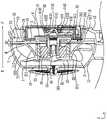
图4是本实用新型便携式无叶风扇自左向右的剖视图;4 is a cross-sectional view of the portable bladeless fan of the present utility model from left to right;
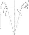
图5是图4中导风面的示意图;Fig. 5 is the schematic diagram of the wind guide surface in Fig. 4;
图6是本实用新型便携式无叶风扇另一实施例的旋转座和加压座的示意图;6 is a schematic diagram of a rotary base and a pressure base of another embodiment of the portable bladeless fan of the present invention;
图7是本实用新型便携式无叶风扇中壳体透明显示时的左视图;7 is a left side view of the portable bladeless fan of the present utility model when the casing is transparently displayed;
图8是本实用新型便携式无叶风扇自前向后的剖视图;8 is a cross-sectional view of the portable bladeless fan of the present invention from front to back;
图9是本实用新型便携式无叶风扇隐藏盖板且壳体透明显示时的后视图;9 is a rear view of the portable bladeless fan of the present invention when the cover plate is hidden and the casing is transparently displayed;
图10是本实用新型便携式无叶风扇中功能部件的立体分解图。10 is an exploded perspective view of the functional components in the portable bladeless fan of the present invention.
具体实施方式Detailed ways
为便于更好地理解本实用新型的目的、结构、特征以及功效等,现结合附图和具体实施方式对本实用新型作进一步说明。In order to facilitate a better understanding of the purpose, structure, features and efficacy of the present invention, the present invention will now be further described with reference to the accompanying drawings and specific embodiments.
为了更加方便理解本实用新型的技术方案,说明书附图中的三维坐标轴中的X轴所在方向定义为左右方向,Y轴定义为前后方向,Z轴定义为上下方向。本申请中的空气、风和气流指的均为气体。In order to more easily understand the technical solution of the present invention, in the three-dimensional coordinate axes in the accompanying drawings, the X-axis is defined as the left-right direction, the Y-axis is defined as the front-rear direction, and the Z-axis is defined as the up-down direction. Air, wind and airflow in this application refer to gases.
参考图1至图3,图1为本实用新型便携式无叶风扇A的立体图,图2和图3为本实用新型便携式无叶风扇A的两个不同角度的分解图,本实用新型便携式无叶风扇A包括加压混流产生器100和便携携带部200。Referring to FIGS. 1 to 3, FIG. 1 is a perspective view of the portable bladeless fan A of the present invention, and FIGS. 2 and 3 are exploded views of two different angles of the portable bladeless fan A of the present invention. The fan A includes the pressurized
参考图1,在本实施例中,所述便携式无叶风扇A为手持式无叶风扇,所述便携携带部200设于所述加压混流产生器100的下方,所述便携携带部200 为供用户手持的手柄。当然,所述便携式无叶风扇A也可以是配置有夹子的夹持风扇,或配置有用于缠绕的弯曲定型件的百变风扇,或配置有支架的桌面风扇,或配置有伸缩支架的落地风扇,不以此为限制。所述便携携带部200上设有半导体制冷件201,用户通过所述便携携带部200可将所述便携式无叶风扇A 随身携带,同时所述半导体制冷件201可以根据用户与所述便携携带部200接触的部分的温度自动对应调节制冷温度,提升用户携带的舒适感。应当理解,所述便携式无叶风扇A用于散热降温,对应所述便携携带部200上设有半导体制冷件201,提升用户携带的舒适感;当然在所述便携式无叶风扇A中加上加热元件(未图示),也可以用于保温取暖,对应所述便携携带部200上可设有暖温件(未图示)对人体接触部分自动调节温度,以温暖人体接触部分,提升用户携带的舒适感。Referring to FIG. 1 , in this embodiment, the portable bladeless fan A is a hand-held bladeless fan, and the portable carrying
结合图2和图3,在本实施例中,所述便携携带部200的内部可容纳电池(未标识,下同),所述便携携带部200可外露设置开关按键(未标识,下同)和充电口(未图示,下同),所述电池为所述便携式无叶风扇A供电,所述开关按键用于调节风速和开关,所述充电口用于外接电源对所述电池充电,当所述便携式无叶风扇A为其他形态的风扇(例如上述的夹持风扇、百变风扇、桌面风扇等)时,所述电池、开关按键和充电口的位置可以对应调整。当然,为了追求更加轻薄,所述便携式无叶风扇A内也可以不设置所述电池,通过设置接口(未图示)与外部移动电源连接同样可以实现便携携带。2 and 3, in this embodiment, the interior of the portable carrying
参考图1至图3,所述加压混流产生器100包括壳体1、加压件3和混流风扇2,所述壳体1、所述加压件3和所述混流风扇2的径向截面的轮廓均大体呈圆形,当然所述壳体1、所述加压件3和所述混流风扇2还可以是其他形状,并不以此为限制。所述加压件3连接所述壳体1的前侧,所述加压件3和所述壳体1一体成型,当然不以此为限制。所述混流风扇2连接于所述加压件3的后侧,且位于所述壳体1内,所述混流风扇2绕转轴24旋转产生气流。所述便携式无叶风扇A的进风端R位于后端,出风端F位于前端,垂直于所述转轴24 且穿过所述转轴24的延伸方向为径向,平行于所述转轴24的方向为轴向。Referring to FIGS. 1 to 3 , the pressurized
参考图2、图3、图4和图7,所述壳体1的最大径向截面的直径是所述壳体1前后两端的长度的2-2.2倍,以使所述加压混流产生器100轻薄化,并且相较于市面上已有的手持风扇极小的出风面,本申请的所述便携式无叶风扇A在保证风量和风压的前提下,具有更大的出风面积,当用户使用时(比如手持或立于平面上时),同样的距离下,本申请的所述便携式无叶风扇A吹出的风可以接触到用户更多部位,吹风效果更好。所述壳体1的后侧设有进气板13,所述进气板13上设有进气部14,所述壳体1的前侧连接所述加压件3,所述加压件 3和所述壳体1在靠近所述出风端F的径向之间形成出气部15,所述进气部14 和所述出气部15在所述壳体1内相连通。在所述进气板13的后侧,固定有一个盖板16,所述盖板16上设有气孔161,所述气孔161的尺寸小于所述进气部 14的尺寸,以避免手指或者其他异物等从所述进气部14进入所述壳体1内,提高了使用的安全性。所述盖板16和所述进气板13之间具有距离,且所述进气板13的至少部分向前凹设,所述盖板16的至少部分向后凹设,以在所述盖板16上的气孔161的尺寸较小的情况下,增加所述进气板13和所述盖板16之间径向上的进风路径,同时所述进气部14的尺寸较大,因此风量不会由于设置了尺寸较小的所述气孔161的所述盖板16而受到影响。所述壳体1进一步分为前后配合的第一壳体11和第二壳体12,所述第一壳体11和所述第二壳体12通过固定结构相互固定,所述混流风扇2在径向上基本对应设置于所述第一壳体11 内,所述加压件3在径向上基本对应设置于所述第二壳体12内。所述第一壳体 11前后两端的长度和所述第二壳体12前后两端的长度比值为1-1.5,能在实现轻薄化的同时合理平衡好风量和风压的关系。2, 3, 4 and 7, the diameter of the largest radial section of the
参考图2、图4、图8和图9,所述混流风扇2包括旋转座21和多个第一叶片22,所述旋转座21包括自所述进风端R向所述出风端F呈径向增大的导风面211,多个所述第一叶片22连接且等距布置于所述导风面211,每一所述叶片包括与所述导风面211连接的第一叶根部221,以及远离所述导风面211的第一叶顶部222。所述第一叶片22自所述进风端R向所述出风端F且沿所述导风面211的周向以预定角度螺旋延伸,从所述进风端R向所述出风端F看,任意相邻的两个所述第一叶片22之间在所述进风端R具有第一间隔J1,在所述出风端F具有第二间隔J2,所述第一间隔J1与所述第二间隔J2的比值范围为0.5-0.9,有利于增大进风量。结合参考图3,所述旋转座21大致为截锥状,所述旋转座 21在所述进风端R的径向截面积小于所述旋转座21在所述出风端F的径向截面积,所述旋转座21在所述出风端F具有相对较大的径向截面,所述旋转座21 在所述出风端F向所述进风端R凹设形成容纳部23,所述容纳部23用于容纳电机等部件,所述混流风扇2使用的电机为外转子无刷电机25,使用寿命可达1万5小时,并且没有了有刷电机运转时产生的电火花,可极大减少电火花对遥控无线电设备的干扰;无刷的方式运转时摩擦力大大减小,运行顺畅,降噪效果好。并且所述混流风扇2和所述加压件3的连接结构也容纳于所述容纳部23,极好地利用空间,所述转轴24自所述容纳部23的后壁向前凸出,所述加压件3 的后侧向后凸出形成凸柱33,所述转轴24固定于所述凸柱33。同时,所述外转子无刷电机25容纳于所述旋转座21的所述容纳部23内,以实现所述旋转座 21与所述加压件3相互独立隔离。2 , 4 , 8 and 9 , the mixed-
参考图2、图4和图7,所述进气板13与所述旋转座21的后端之间具有安全受压距离D1,以允许所述进气板13在满足材料性能所允许的压力范围内的最大受压形变。所述进气板13与所述旋转座21的后端之间的距离为4.0-4.5mm (毫米,下同),以便在进风端R具有空间供大风量进入,同时具有空间供进气板13受到大风量时发生最大受压形变。结合参考图9,所述进气板13的径向截面积大于或等于所述旋转座21的最大径向截面积,以保证足够的进风量,并实现降噪,以将尖锐噪声转为低沉声;且所述进气板13的径向截面积小于或等于所述第一叶顶部222在所述进风端R形成的进风窗2221面积,以使所述第一叶顶部222在所述进风端R形成的进风窗2221处就开始形成较大风压。在本实施例中,所述进气板13的径向截面半径为27.7mm,所述旋转座21的后端的径向截面半径为15.5mm,当然并不以此为限制。另外,所述进气板13的径向截面积小于或等于所述加压座31在所述出风端F的径向截面积,所述进气板13上的所述进气部14被前侧的所述加压座31遮挡,使用时,从前往后看不到所述进气部14,也就是说,所述进气部14的光不会从后方投射到前方,以降低所述混流风扇2的转动对人眼的影响。在所述进风端R所述第一叶顶部222相对于所述第一叶根部221更靠近所述进气板13,以增强所述混流风扇2的抽吸能力。Referring to FIG. 2 , FIG. 4 and FIG. 7 , there is a safe pressure distance D1 between the
参考图4和图5,所述导风面211的至少部分朝所述转轴24凹陷。具体地,所述导风面211包括入口面2111、出口面2113以及在所述入口面2111和所述出口面2113之间延伸的过渡面2112,在本实施例中,所述入口面2111定向为与所述转轴24形成倾斜角,以限定从所述进风端R通向所述过渡面2112的倾斜流动路径,所述出口面2113定向为与所述转轴24基本平行,以限定从所述过渡面2112向所述出风端F的轴向流动路径。Referring to FIG. 4 and FIG. 5 , at least part of the
参考图6,也可以是所述入口面2111定向为与所述转轴24形成倾斜角,以限定从所述进风端R通向所述过渡面2112的倾斜流动路径,所述出口面2113 定向为与所述转轴24形成倾斜角,以限定从所述过渡面2112通向所述出风端F 的倾斜流动路径。当然在其他实施例中,也可以是所述入口面2111定向为与所述转轴24基本平行,以限定从所述进风端R通向所述过渡面2112的轴向流动路径,所述出口面2113定向为与所述转轴24形成倾斜角,以限定从所述过渡面2112向所述出风端F的倾斜流动路径;也可以是所述入口面2111定向为与所述转轴24基本平行,以限定从所述进风端R通向所述过渡面2112的轴向流动路径,所述过渡面2112与所述转轴24形成倾斜角,以限定在所述过渡面2112 上的倾斜流动路径,所述出口面2113定向为与所述转轴24基本平行,以限定从所述过渡面2112向所述出风端F的轴向流动路径。Referring to FIG. 6 , the
所述入口面2111、所述过渡面2112和所述出口面2113三者中至少一个定向为与所述转轴24形成倾斜角,以限定至少部分倾斜流动路径,使得从所述进风端R进来的靠近所述转轴24的轴向风,经过倾斜流动路径改变为相对远离所述转轴24的轴向风或倾斜风,有利于在减少风量损耗,并且增大风压,增大送风距离。At least one of the
应当理解,所述导风面211的至少部分可以是朝所述转轴24凹陷,以使所述混流风扇2聚集扩大了风量并形成高风压,对所述外转子无刷电机25的噪音和风噪实现关闭处理,以将尖锐噪声转为低沉声。当然,所述导风面211也可以是倾斜的平面,或者也可以是至少部分朝远离所述转轴24凸出,并不以此为限制。It should be understood that at least part of the
参考图2、图4、图6和图7,所述加压件3包括加压座31和多个第二叶片 32,所述加压座31包括自所述进风端R向所述出风端F径向增大的加压面311,多个所述第二叶片32连接且等距布置于所述加压面311,每一所述第二叶片32 包括与所述加压面311连接的第二叶根部321,以及远离所述加压面311的第二叶顶部322。所述第二叶片32包括导流曲面323,所述导流曲面323靠近所述第一叶片22,从后往前看,所述第二叶片32朝逆时针方向倾斜向前延伸,所述混流风扇2形成的斜流风经由所述导流曲面323后形成直流风平行所述转轴24吹出,以增大吹风距离,并对所述混流风扇2形成的风快速增压。所述第二叶顶部322连接所述壳体1,所述旋转座21通过固定配合结构连接所述加压座31,所述混流风扇2通过所述加压件3相对固定于所述壳体1内。其中,所述加压件3在所述出风端F的最大径面的半径值为28-35mm,在确保足够的风量和风压的情况下,扩大吹风面积。Referring to FIG. 2 , FIG. 4 , FIG. 6 and FIG. 7 , the pressurizing
同时所述第二叶片32对经过的风进行梳理和转化,减少紊流、噪音和震动,减少了紊流串扰发出的噪音,实现降噪,以将尖锐噪声转为低沉声;且在很大程度上提升了静压,并减少了能耗,加强了所述混流风扇2出风的集中性,所述第二叶片32对所述混流风扇2形成的风均流且增加风压。所述第二叶片32 包括与所述加压面311连接的第二叶根部321,以及远离所述加压面311的第二叶顶部322,所述第二叶顶部322连接所述壳体1,所述第二叶根部321前后两端的连线与所述第二叶顶部322前后两端的连线之间形成锐角,也就是说所述壳体1与所述加压面311向前延伸的同时彼此靠近延伸,使得风从所述壳体1 和所述加压面311之间的缝隙加压出风,有利于增大风力和送风距离。At the same time, the
参考图3、图4、图6和图7,所述加压座31也大致为截锥状,所述加压座 31在所述进风端R的径向截面积小于所述加压座31在所述出风端F径向截面积,所述加压座31在所述出风端F具有相对较大的径向截面,所述加压座31 在所述出风端F向所述进风端R凹设形成容腔34,所述容腔34用于容纳功能部件4。同时所述加压座31和所述壳体1在所述出风端F形成所述出气部15,所述加压座31在所述出风端F的径向截面较大,风在所述出风端F从所述加压座31和所述壳体1之间的缝隙加压出风,有利于实现所述加压座31容纳功能和加压功能的复用。Referring to FIG. 3 , FIG. 4 , FIG. 6 and FIG. 7 , the
参考图3、图4、图6和图7,所述加压面311的至少部分自所述进风端R 向所述出风端F径向增大,同时,所述加压面311的至少部分朝所述转轴凹陷。具体地,所述加压面311自所述进风端R向所述出风端F先径向增大,再平行所述转轴24向前延伸,当然在其他实施例中,所述加压面311自所述进风端R 向所述出风端F也可以是先平行所述转轴24向前延伸,再径向增大,或总体径向增大,或总体径向不变,或至少部分径向减小,并不以此为限制。所述容腔 34的径向截面为圆形,所述容腔34包括位于后方的底面341和连接所述底面 341且位于径向上的周壁342,对应所述加压面311,所述周壁342自所述底面 341先向前径向增大,再平行所述转轴24向前延伸,以便于所述功能部件4的固定和拆卸。当然所述周壁342也可以整体均自所述底面341向前径向增大,或者所述周壁342也可以自所述底面341先平行所述转轴24向前延伸,再向前径向增大,并不以此为限制。Referring to FIG. 3 , FIG. 4 , FIG. 6 and FIG. 7 , at least part of the
参考图2、图4和图7,所述加压件3和所述混流风扇2两者与所述壳体1 之间形成加压导流通道T,所述加压导流通道T在所述进风端R的径向截面积大于在所述出风端F的径向截面积,空气从所述进气部14进入所述加压导流通道T,在所述加压导流通道T中形成加压混流后自所述出气部15排出。风从所述进风端R轴向进入所述混流风扇2后,从出风端F离开,所述混流风扇2结合了轴流式风扇风量大的优点和离心式风扇风压大的优点。同时,所述混流风扇2和所述加压件3两者与所述壳体1之间形成的所述加压导流通道T,在所述进风端R的径向截面积大,有利于吸聚空气,增大风量;在所述出风端F的径向截面积小,有利于压缩空气,增高风压。所述混流风扇2斜向出风的特点进一步增加风压,送风距离加大,从而在体积较小的便携式无叶风扇A上,实现大风量和高风压,实现快速降温,提升用户使用体验。Referring to FIG. 2 , FIG. 4 and FIG. 7 , a pressurizing guide channel T is formed between the pressurizing
参考图4、图6和图7,所述混流风扇2和所述加压件3在轴向上紧邻间隔设置,即所述旋转座21和所述加压座31在轴向上紧邻间隔设置,同时所述旋转座21在所述出风端F的径向截面和所述加压座31在所述进风端R的径向截面均为圆形,两者半径相差极小,在本实施例中两者半径的差值小于2mm,当然不以此为限制,只要能使得所述加压面311和所述导风面211在轴向上也是紧邻间隔设置,以阻挡风进入所述旋转座21和所述加压座31之间的等效无缝衔接间隔D2,被阻挡进入所述旋转座21和所述加压座31之间的等效无缝衔接间隔D2的风被后端所述混流风扇2形成的风迎面直吹,从而继续向前流动,使风更平顺地由所述导风面211与所述壳体1之间所述加压导流通道T的部分进入所述加压面311与所述壳体1之间所述加压导流通道T的部分,降低涡流损失,同时减少紊流串扰的噪音。具体地,所述旋转座21和所述加压座31在轴向上的等效无缝衔接间隔D2为1-1.5mm,以使所述混流风扇2形成的风顺畅地流向所述加压件3,当然并不以此为限制,只要能使减少风进入所述旋转座21和所述加压座31之间的等效无缝衔接间隔D2即可。4 , 6 and 7 , the mixed-
参考图6,所述导风面211包括邻近所述加压面311一端的第一延伸段2114,所述加压面311包括邻近所述导风面211一端的第二延伸段312,所述第一延伸段2114和所述第二延伸段312的延伸方向相同,以使所述导风面211和所述加压面311之间的衔接更加顺畅。Referring to FIG. 6 , the
参考图7,所述第一叶片22和所述第二叶片32在轴向上紧邻间隔设置以形成等效隔断间隙D3,所述第一叶片22和所述第二叶片32之间的最小等效隔断间隙D3为1-1.5mm,以隔断所述混流风扇2在所述出风端F产生的气流沿所述第一叶片22和所述第二叶片32轴向间的间隙回流至所述进风端R,并隔断相邻两个所述第二叶片32之间的风发生串流,从而梳理气流并增加气压,实现导风、降噪的效果。当然,所述第一叶片22和所述第二叶片32的最小等效隔断间隙 D3并不以此为限制,只要能使所述第一叶片22间的气流顺畅流向所述第二叶片32间,减少回流损耗即可。Referring to FIG. 7 , the
参照图2、图7和图9,从后往前的方向看,所述第一叶片22连接所述导风面211且朝顺时针方向倾斜向前延伸,所述第二叶片32连接所述加压面311 且朝逆时针倾斜向前延伸,所述第一叶片22连接在所述导风面211的前后两端的连线与所述第二叶片32连接在所述加压面311的前后两端的连线形成夹角,以增大风压。并且,所述第二叶片32的曲率大于所述第一叶片22的曲率,以进一步增大风压。当然所述第一叶片22和所述第二叶片32的曲率并不以此为限制。2 , 7 and 9 , viewed from the rear to the front, the
参考图2和图9,在本实施例中,所述第一叶片22的数量为7个,所述第二叶片32的数量为12个,在其他实施例中,也可以是所述第一叶片22的数量与所述第二叶片32的数量的比值范围为3/7-4/5,当然并不以此为限制,只要能保证所述便携式无叶风扇A的对风较好的抽吸能力以及对风较好的增压能力即可。Referring to FIG. 2 and FIG. 9 , in this embodiment, the number of the
参考图4和图6,自所述进风端R至所述出风端F,所述混流风扇2和所述加压座31整体径向增大呈喇叭状以形成外扩的加压斜面M,具体地,所述旋转座21和所述加压座31整体径向增大呈喇叭状以形成外扩的加压斜面M,所述加压斜面M增加气流的加压行程。所述加压斜面M包括所述导风面211和所述加压面311,两段式加压,且两段加压行程均增大,使得加压效果较好。Referring to FIG. 4 and FIG. 6 , from the air inlet end R to the air outlet end F, the
参考图3、图4、图6和图7,所述旋转座21前后两端的轴向长度是所述加压座31前后两端的轴向长度的0.8-1或1-1.5倍,以使得气流经由所述第一叶片 22进行高压聚风后,通过所述第二叶片32进行等效距离梳理,确保从所述加压件3产生的最终气流的高压风量和外部的负压风量所构造的最大使用风量、以及所述最大使用风量的聚合送风距离。应当理解,所述加压件3产生的最终气流风压高,可以带动所述壳体1外附近的负压空气,从而进一步增大风量。优选的,所述混流风扇2前后两端的轴向长度和所述加压件3前后两端的轴向长度为1:1,能满足所述便携式无叶风扇A使用场景下的大风量的要求,并且产品轻薄化;并且1:1的比例作为手持,其外观观感更加符合对称的审美观。所述加压件3在所述出风端F设有用于收纳所述功能部件4的所述容腔34,在所述加压座31前后两端的轴向长度受限的情况下,所述容腔34的深度值与所述加压件3从所述进风端R到所述出风端F的长度值之间的差值小于第一差异值,且所述容腔34的最大开口的半径值与所述加压件3在所述出风端F的最大径面的半径值的差值小于第二差异值,以实现所述加压件3在加压功能和容纳功能的复用。并且在所述旋转座21和所述加压座31的厚度受限的情况下,通过外扩的所述加压斜面M,还可以使得所述容腔34邻近所述旋转座21的底面341的半径值与所述壳体1在所述出风端F的径向截面的半径值小于第三差异值,以在所述容腔34的深度值受限的情况下,通过增加所述容腔34邻近所述旋转座 21的底面341径向截面积,来增加所述容腔34容纳所述功能部件4的容纳空间。所述第一差异值和所述第二差异值均为1.3-1.7mm,所述第三差异值为 6.2-6.8mm,以保证所述容腔34在径向上具有充足的容纳所述功能部件4的容纳空间,同时保证气流在所述出风端F从所述加压斜面M和所述壳体1之间形成的缝隙加压排出。当然在其他实施例中,所述第一差异值、所述第二差异值和所述第三差异值还可以对应调整为其他值,只要能平衡好所述加压件3的容纳功能和加压功能即可。3, 4, 6 and 7, the axial length of the front and rear ends of the
参考图4、图6和图7,所述加压斜面M与所述壳体1形成所述加压导流通道T,所述加压斜面M包括所述导风面211和所述加压面311。所述加压斜面M与所述壳体1的配合,实现降噪,以将尖锐噪声转为低沉声。所述加压导流通道T包括相连接的第一通道T1和第二通道T2,在径向上所述混流风扇2的所述导风面211和所述第一壳体11之间形成所述第一通道T1,在径向上所述加压座31的所述加压面311和所述第二壳体12之间形成所述第二通道T2,所述第一通道T1的最小径向截面积大于或等于所述第二通道T2的最大截面积。Referring to FIG. 4 , FIG. 6 and FIG. 7 , the pressurized inclined surface M and the
参考图4、图6和图7,在径向上,所述第一壳体11包括朝向所述导风面 211的第一引流面111,所述导风面211和所述第一引流面111均为环状,所述导风面211的至少部分径向凹陷形成凹面,所述第一引流面111自所述进风端R 向所述出风端F径向增大,且所述第一引流面111的至少部分径向凸出形成凸面,使得所述第一通道T1的结构在加压的同时可聚集形成大风量。当然,这只是所述导风面211和所述第一引流面111的一种形态,并不以此为限制。Referring to FIG. 4 , FIG. 6 and FIG. 7 , in the radial direction, the
参考图4、图6和图7,在径向上,所述第二壳体12包括朝向所述加压面 311的第二引流面121,所述加压面311和所述第二引流面121均为环状,所述加压面311的至少部分径向增大且径向凹陷形成凹面,所述第二引流面121自所述进风端R向所述出风端F径向减小,且所述第二引流面121的至少部分径向凸出形成凸面,使得所述第二通道T2的结构可将后方形成的大风量高风压的风,进一步快速加压形成高风压的风。当然,这只是所述加压面311和所述第二引流面121的一种形态,并不以此为限制。Referring to FIGS. 4 , 6 and 7 , in the radial direction, the
所述第一引流面111和所述第二引流面121均为径向凸出形成的凸面,且所述第一引流面111和所述第二引流面121自所述进风端R至所述出风端F先径向增大后径向减小形成顺畅完整的弧面,所述第一引流面111和所述第二引流面121不仅具有增加风量、风压的作用,同时也提高了所述外壳的美观性。所述第二引流面121在所述出风端F与所述转轴24之间的径向距离,大于所述第一引流面111在所述进风端R与所述转轴24之间的径向距离,有利于将靠近中间的所述转轴24的风带向径向上相对远离所述转轴24的位置吹出,使得增大送风距离。Both the
参考图4至图6,所述进风端R的轴向风改变为沿所述导风面211倾斜向前流动,可以使更靠近轴向的风向外倾斜流动;所述混流风扇2在所述出风端F 的倾斜风改变为沿所述加压面311倾斜向前流动,进一步倾斜向外流动,以在所述加压件3靠近轴心的部位留有足够的空间,足够的空间可用于收纳所述功能部件4。所述导风面211前后两端的连线与所述转轴24形成第一角度a,所述加压面311的前后两端的连线与所述转轴24形成第二角度b,所述第一角度a 大于所述第二角度b,以在增加风压的同时减少风量的损耗。所述第一角度a的范围为30-45度,所述第二角度b的范围为5-15度。所述导风面211至少部分朝所述转轴24凹陷,所述进风端R的轴向风沿斜率跳变式增大的所述导风面211 流动进行快速增压。所述加压面311自所述进风端R向所述出风端F先径向增大后径向不变,且所述加压面311径向增大的部分和径向不变的部分均为平面,所述混流风扇2形成的风沿斜率渐变式减小的所述加压面311进行二次加压。风经由所述导风面211的快速增压和加压面311的二次加压,形成高压风,使得所述加压混流产生器100的吹风效果好,送风距离长;同时,两段倾斜的结构也有导风、降噪的效果。Referring to FIGS. 4 to 6 , the axial wind of the air inlet R is changed to flow obliquely forward along the
参考图4、图7和图8,自所述进风端R至所述出风端F,所述导风面211 的至少部分朝所述转轴24凹陷,以使所述混流风扇2聚集风量并形成第一高风压;如图4,从左往右看,所述第一叶顶部222与所述壳体1在径向上的径向空隙的距离自所述进风端R向所述出风端F呈减小的趋势,但结合图8,所述第一叶顶部222与所述壳体1之间的最小径向空隙的距离维持在等效隔断距离D4 的误差范围内,以隔断所述混流风扇2在所述出风端F产生的气流绕所述最小径向空隙回流至所述混流风扇2在所述进风端R,从而增加第二高风压,并且减少了紊流串扰的噪音;任一相邻的两个所述第一叶片22之间的距离自所述进风端R向所述出风端F逐渐增大,以增加第三高风压;所述第二叶片32对所述混流风扇2形成的风均流且增加第四高风压。Referring to FIGS. 4 , 7 and 8 , from the air inlet end R to the air outlet end F, at least part of the
在所述进风端R聚集大风量的基础上形成所述第一高风压,同时增加所述第二高风压、所述第三高风压和所述第四高风压,所述混流风扇2具有形成大风量和高风压的能力,以在体积较小的所述便携式无叶风扇A中,制造大风量和高风压的风,且增大送风距离,极好地满足用户的需求。The first high wind pressure is formed on the basis of the large air volume gathered at the air inlet end R, and the second high wind pressure, the third high wind pressure and the fourth high wind pressure are simultaneously increased. The mixed-
参考图2、图3和图10,所述功能部件4可拆卸地固定于所述容腔34,所述底面341上设有出风口343,所述功能部件4固定于所述容腔34时,所述出风口343的风经由所述功能部件4的表面向前逸散。应当理解,所述功能部件4 可通过卡扣结构或磁吸结构等固定结构可拆卸地固定于所述容腔,所述功能部件4卸下时,所述便携式无叶风扇A去除所述功能部件4同样可以正常使用,所述功能部件4是赋予了所述便携式无叶风扇A额外的功能,丰富了所述便携式无叶风扇A的使用场景。Referring to FIG. 2 , FIG. 3 and FIG. 10 , the
参考图2、图3、图4和图10,在本实施例中,所述功能部件4用于加湿喷雾,所述功能部件4包括本体41及盖设于所述本体41前侧的前盖42,所述本体41包括储水件411和雾化件412,所述储水件411设有加水口413、出雾口 414和排气口415,所述加水口413用于加水,所述出雾口414位于所述储水件 411的前侧,所述雾化件412对应设于所述出雾口414的前方,且与所述出雾口 414密封连接,所述排气口415用于排出所述储水件411内的空气,当然也可以不设置所述排气口415。所述雾化件412用于将所述储水件411中的水雾化喷出,所述前盖42设有排雾口421,所述排雾口421显露所述雾化件412的至少部分。所述容腔34的壁面上设有第一触点344,所述功能部件4上对应设置连接所述雾化件412的第二触点43,当所述功能部件4收容于所述容腔34内时,所述第二触点43与所述第一触点344电性连接,以向所述雾化件412供电。当然在其他实施例中,所述功能部件4可以是用于可拆换式设置的IP形象物品,所述容腔34可外露,或通过至少部分透明的所述前盖42进行遮盖,以提升用户对IP形象物品的交互。通过设置为可拆换式,避免了不同的合作方要定制不同的模具,一套模具就能对接多个IP合作方,能降低40%左右的IP合作方生产成本;外露的IP形象物品,增加用户直接触摸IP形象物品,改变传统的使用体验。所述功能部件4也可以是香薰组件,也可以是加湿和香薰结合的组件,也可以是用于收纳USB线束,也可以是带LED灯的镜子等,并不以此为限制。Referring to FIG. 2 , FIG. 3 , FIG. 4 and FIG. 10 , in this embodiment, the
现有的手持加湿风扇通常在外壳前侧设置凸出的储水箱,在不能影响出风的情况下,储水箱的装水量远远满足不了经常需要雾化加湿的需求,本申请中的所述储水件411的装水量为现有市面上的手持加湿风扇的装水量的3倍,可以延长3倍以上的使用时间。Existing hand-held humidification fans are usually provided with a protruding water storage tank on the front side of the casing. Under the condition that the air outlet cannot be affected, the water storage tank can far from meeting the requirement of frequent atomization and humidification. The
在本实施例中,所述本体41的前端与所述壳体1的前端平齐,使所述加压混流产生器一体化、轻薄化,便携、美观,同时使所述储水件411不容易被刮擦碰撞,进而避免了所述储水件411的结构被破坏而出现漏水的情况,安全性能更高。当然在其他实施例中,所述本体41的前端也可以是相对所述壳体1的前端向后凹陷。In this embodiment, the front end of the
参考图2、图3、图4和图10,所述出雾口414包括通孔4141,位于所述通孔4141周向的第一配合部4142,以及位于所述通孔4141中的固持部4143,所述第一配合部4142自前向后形成凹陷,并使所述通孔4141在周向上具有深度,所述固持部4143连接所述通孔4141的内壁面。所述雾化件412包括雾化片4121及设于所述雾化片4121周向的第二配合部4122,所述第二配合部4122 与所述第一配合部4142配合将所述雾化片4121固定于所述通孔4141的前方。所述第一配合部4142自前向后的凹陷,有利于设置所述雾化件412与所述储水件411之间的配合固定结构,并且极好地利用空间,外形美观。所述本体41还包括设于所述储水件411内的吸水件416,所述吸水件416至少自所述储水部的底部向上延伸至所述储水部的中间,所述吸水件416的至少部分位于所述通孔 4141中,且夹设于所述固持部4143和所述雾化片4121之间。当所述便携式无叶风扇A使用时,所述储水件411竖直设置,由于所述吸水件416的设置,低于所述雾化片4121的水仍可以被所述吸水件416吸收传递至所述雾化片4121进行雾化,使所述雾化片4121的位置不被限制设置于所述储水件411靠近底部的位置,有利于增大所述储水件411的储水容量,并且使所述储水件411中的水均能很好地被雾化喷出。2 , 3 , 4 and 10 , the
以上详细说明仅为本实用新型之较佳实施例的说明,非因此局限本实用新型之专利范围,所以,凡运用本创作说明书及图示内容所为之等效技术变化,均包含于本创作之专利范围内。The above detailed description is only the description of the preferred embodiment of the present invention, and is not intended to limit the scope of the patent of the present invention. Therefore, any equivalent technical changes made by using the description and illustrations of this creation are included in this creation. within the scope of the patent.
Claims (12)
Applications Claiming Priority (2)
| Application Number | Priority Date | Filing Date | Title |
|---|---|---|---|
| CN2021223506263 | 2021-09-27 | ||
| CN202122350626 | 2021-09-27 |
Publications (1)
| Publication Number | Publication Date |
|---|---|
| CN216742070Utrue CN216742070U (en) | 2022-06-14 |
Family
ID=80305947
Family Applications (24)
| Application Number | Title | Priority Date | Filing Date |
|---|---|---|---|
| CN202122972208.8UActiveCN216742070U (en) | 2021-09-27 | 2021-11-30 | Pressurized mixed flow generator and portable bladeless fan with same |
| CN202111447538.3AActiveCN114183385B (en) | 2021-09-27 | 2021-11-30 | Pressurized mixed flow generator and portable bladeless fan equipped with the same |
| CN202122972198.8UActiveCN216742069U (en) | 2021-09-27 | 2021-11-30 | Pressurized mixed flow generator and portable bladeless fan equipped therewith |
| CN202122972162.XUActiveCN216742067U (en) | 2021-09-27 | 2021-11-30 | Pressurized mixed flow generator and portable bladeless fan with same |
| CN202122980532.4UActiveCN216742072U (en) | 2021-09-27 | 2021-11-30 | Pressurized mixed flow generator and portable bladeless fan with same |
| CN202122974743.7UActiveCN216842288U (en) | 2021-09-27 | 2021-11-30 | Pressurized mixed flow generator and portable bladeless fan equipped therewith |
| CN202111447539.8AActiveCN114183386B (en) | 2021-09-27 | 2021-11-30 | Pressurized mixed flow generator and portable bladeless fan equipped with the same |
| CN202122972174.2UActiveCN216742068U (en) | 2021-09-27 | 2021-11-30 | Mixed flow fan, pressurized mixed flow generator and portable bladeless fan equipped therewith |
| CN202111445161.8AActiveCN114087218B (en) | 2021-09-27 | 2021-11-30 | Handheld bladeless fan |
| CN202123156177.5UActiveCN217029355U (en) | 2021-09-27 | 2021-12-06 | Hand-held fan |
| CN202123124225.2UActiveCN217029352U (en) | 2021-09-27 | 2021-12-10 | Portable bladeless fan |
| CN202123143736.9UActiveCN216518757U (en) | 2021-09-27 | 2021-12-10 | Portable bladeless fan |
| CN202111518220.XAPendingCN114215774A (en) | 2021-09-27 | 2021-12-10 | Portable bladeless fan |
| CN202510930119.7APendingCN120720246A (en) | 2021-09-27 | 2021-12-10 | portable bladeless fan |
| CN202111519414.1APendingCN114215775A (en) | 2021-09-27 | 2021-12-10 | Portable Bladeless Fan |
| CN202123143489.2UActiveCN216518756U (en) | 2021-09-27 | 2021-12-10 | Portable bladeless fan |
| CN202123115702.9UActiveCN217029351U (en) | 2021-09-27 | 2021-12-10 | Portable bladeless fan |
| CN202510923424.3APendingCN120701591A (en) | 2021-09-27 | 2021-12-10 | Portable bladeless fan |
| CN202510922070.0APendingCN120701590A (en) | 2021-09-27 | 2021-12-10 | portable bladeless fan |
| CN202510922055.6APendingCN120626515A (en) | 2021-09-27 | 2021-12-10 | portable bladeless fan |
| CN202111510129.3APendingCN114215773A (en) | 2021-09-27 | 2021-12-10 | Portable Bladeless Fan |
| CN202220207524.8UActiveCN217029363U (en) | 2021-09-27 | 2022-01-25 | Hanging neck type fan |
| CN202220318943.9UActiveCN217502037U (en) | 2021-09-27 | 2022-02-17 | Portable Fan |
| CN202221164340.4UActiveCN217950721U (en) | 2021-09-27 | 2022-05-16 | Portable bladeless fan |
Family Applications After (23)
| Application Number | Title | Priority Date | Filing Date |
|---|---|---|---|
| CN202111447538.3AActiveCN114183385B (en) | 2021-09-27 | 2021-11-30 | Pressurized mixed flow generator and portable bladeless fan equipped with the same |
| CN202122972198.8UActiveCN216742069U (en) | 2021-09-27 | 2021-11-30 | Pressurized mixed flow generator and portable bladeless fan equipped therewith |
| CN202122972162.XUActiveCN216742067U (en) | 2021-09-27 | 2021-11-30 | Pressurized mixed flow generator and portable bladeless fan with same |
| CN202122980532.4UActiveCN216742072U (en) | 2021-09-27 | 2021-11-30 | Pressurized mixed flow generator and portable bladeless fan with same |
| CN202122974743.7UActiveCN216842288U (en) | 2021-09-27 | 2021-11-30 | Pressurized mixed flow generator and portable bladeless fan equipped therewith |
| CN202111447539.8AActiveCN114183386B (en) | 2021-09-27 | 2021-11-30 | Pressurized mixed flow generator and portable bladeless fan equipped with the same |
| CN202122972174.2UActiveCN216742068U (en) | 2021-09-27 | 2021-11-30 | Mixed flow fan, pressurized mixed flow generator and portable bladeless fan equipped therewith |
| CN202111445161.8AActiveCN114087218B (en) | 2021-09-27 | 2021-11-30 | Handheld bladeless fan |
| CN202123156177.5UActiveCN217029355U (en) | 2021-09-27 | 2021-12-06 | Hand-held fan |
| CN202123124225.2UActiveCN217029352U (en) | 2021-09-27 | 2021-12-10 | Portable bladeless fan |
| CN202123143736.9UActiveCN216518757U (en) | 2021-09-27 | 2021-12-10 | Portable bladeless fan |
| CN202111518220.XAPendingCN114215774A (en) | 2021-09-27 | 2021-12-10 | Portable bladeless fan |
| CN202510930119.7APendingCN120720246A (en) | 2021-09-27 | 2021-12-10 | portable bladeless fan |
| CN202111519414.1APendingCN114215775A (en) | 2021-09-27 | 2021-12-10 | Portable Bladeless Fan |
| CN202123143489.2UActiveCN216518756U (en) | 2021-09-27 | 2021-12-10 | Portable bladeless fan |
| CN202123115702.9UActiveCN217029351U (en) | 2021-09-27 | 2021-12-10 | Portable bladeless fan |
| CN202510923424.3APendingCN120701591A (en) | 2021-09-27 | 2021-12-10 | Portable bladeless fan |
| CN202510922070.0APendingCN120701590A (en) | 2021-09-27 | 2021-12-10 | portable bladeless fan |
| CN202510922055.6APendingCN120626515A (en) | 2021-09-27 | 2021-12-10 | portable bladeless fan |
| CN202111510129.3APendingCN114215773A (en) | 2021-09-27 | 2021-12-10 | Portable Bladeless Fan |
| CN202220207524.8UActiveCN217029363U (en) | 2021-09-27 | 2022-01-25 | Hanging neck type fan |
| CN202220318943.9UActiveCN217502037U (en) | 2021-09-27 | 2022-02-17 | Portable Fan |
| CN202221164340.4UActiveCN217950721U (en) | 2021-09-27 | 2022-05-16 | Portable bladeless fan |
Country Status (7)
| Country | Link |
|---|---|
| EP (1) | EP4411144A4 (en) |
| JP (2) | JP7742189B2 (en) |
| KR (1) | KR20240088808A (en) |
| CN (24) | CN216742070U (en) |
| AU (2) | AU2022349651B2 (en) |
| CA (1) | CA3233163A1 (en) |
| WO (1) | WO2023046145A1 (en) |
Families Citing this family (13)
| Publication number | Priority date | Publication date | Assignee | Title |
|---|---|---|---|---|
| CN216742070U (en)* | 2021-09-27 | 2022-06-14 | 深圳市几素科技有限公司 | Pressurized mixed flow generator and portable bladeless fan with same |
| CN220544885U (en)* | 2023-07-24 | 2024-02-27 | 深圳市几素科技有限公司 | Motor drive control circuit of portable fan |
| CN114508498A (en)* | 2022-03-10 | 2022-05-17 | 陈建元 | A multifunctional bladeless hand-held fan |
| CN116965624A (en)* | 2022-04-22 | 2023-10-31 | 深圳市几素科技有限公司 | Portable multifunctional umbrella and air outlet device |
| CN115434959A (en)* | 2022-09-23 | 2022-12-06 | 珠海格力电器股份有限公司 | Bladeless fan |
| AU2023411862B2 (en)* | 2022-12-19 | 2025-10-09 | Shenzhen JISU Technology Co., Ltd | Portable fan, driving circuit for portable fan, and handheld fan |
| JP2025043343A (en)* | 2022-12-19 | 2025-03-28 | 深▲せん▼市几素科技有限公司 | Portable fan, drive circuit for portable fan, and handheld fan |
| WO2024131243A1 (en)* | 2022-12-21 | 2024-06-27 | 深圳市几素科技有限公司 | Portable fan |
| WO2024260079A1 (en)* | 2023-06-23 | 2024-12-26 | 深圳市几素科技有限公司 | Fan module, motor for portable rotating device and high-speed motor |
| TWI879082B (en) | 2023-09-12 | 2025-04-01 | 宏碁股份有限公司 | Axial-flow heat-dissipation fan |
| WO2025108314A1 (en)* | 2023-11-21 | 2025-05-30 | 深圳市几素科技有限公司 | Fan module |
| WO2025154558A1 (en)* | 2024-01-19 | 2025-07-24 | ニデック株式会社 | Impeller and fan device |
| US12180977B2 (en)* | 2024-04-22 | 2024-12-31 | Guangdong Wanyi Electronics Co., Ltd. | High-speed booster fan module |
Family Cites Families (39)
| Publication number | Priority date | Publication date | Assignee | Title |
|---|---|---|---|---|
| TWI278576B (en)* | 2004-10-07 | 2007-04-11 | Sunonwealth Electr Mach Ind Co | Axial-flow heat-dissipating fan for boosting air pressure |
| JP2009191627A (en)* | 2008-02-12 | 2009-08-27 | Calsonic Kansei Corp | Electric fan device |
| CN102937117A (en)* | 2011-08-15 | 2013-02-20 | 任文华 | Bladeless fan |
| KR101255739B1 (en)* | 2012-10-23 | 2013-04-16 | 오승민 | The induced fan for two impeller for jet fan of track type supply air outlet |
| GB2509111B (en)* | 2012-12-20 | 2017-08-09 | Dyson Technology Ltd | A fan |
| CN105736470A (en) | 2013-02-15 | 2016-07-06 | 任文华 | Fan |
| JP6585349B2 (en)* | 2015-01-15 | 2019-10-02 | 富士工業株式会社 | Blower fan, blower and range hood |
| CN205533339U (en)* | 2016-03-09 | 2016-08-31 | 慈溪市附海佳青电器厂 | Domestic no leaf electric fan |
| CN105864887B (en)* | 2016-03-28 | 2018-12-18 | 广东美的制冷设备有限公司 | Air conditioner indoor unit |
| TWI636195B (en)* | 2017-02-07 | 2018-09-21 | 周書賢 | Air supply device |
| CN206582149U (en)* | 2017-03-22 | 2017-10-24 | 应万信 | A kind of hand-held fan |
| CN207621053U (en)* | 2017-11-02 | 2018-07-17 | 深圳市维特世嘉科技有限公司 | A kind of mirror fan |
| US10525371B1 (en)* | 2017-11-22 | 2020-01-07 | Lorraine Melody Hsu | Bladeless bubble fan |
| KR102072755B1 (en)* | 2018-05-15 | 2020-02-03 | 주식회사 휴로 | Portable air cleaning fan |
| CN208686628U (en)* | 2018-08-14 | 2019-04-02 | 东莞市龙晟电子科技有限公司 | a hand-held fan |
| JP7091194B2 (en)* | 2018-08-30 | 2022-06-27 | シャープ株式会社 | Blower |
| KR102425457B1 (en)* | 2018-10-19 | 2022-07-25 | 엘지전자 주식회사 | A Fan Motor |
| CN209053814U (en)* | 2018-11-20 | 2019-07-02 | 宁波富而保智能科技有限公司 | Handheld fan |
| CN211874763U (en)* | 2018-11-29 | 2020-11-06 | 曾固 | A radial out-shaft fluid counter-rotation action device and fan |
| CN209623001U (en)* | 2018-12-04 | 2019-11-12 | 鑫贺精密电子(东莞)有限公司 | A kind of hand-held refrigeration-type fan |
| CN209892472U (en)* | 2019-01-16 | 2020-01-03 | 深圳市火蜂鸟电子商务有限公司 | Spray fan |
| CN109681471B (en)* | 2019-02-14 | 2023-08-29 | 福建雪人股份有限公司 | Spacing assembly for multistage centrifugal compressor |
| KR102181188B1 (en)* | 2019-02-26 | 2020-11-20 | 이호영 | Portable pan and air purifier with the portable fan |
| CN210220096U (en)* | 2019-05-10 | 2020-03-31 | 重庆大学 | A portable bladeless blower based on semiconductor refrigeration |
| CN112303001B (en)* | 2019-08-02 | 2024-11-29 | 珠海格力电器股份有限公司 | Fan subassembly and have its cabinet air conditioner |
| CN210317846U (en)* | 2019-08-23 | 2020-04-14 | 深圳市航科精机技术有限公司 | Portable fan |
| CN211230887U (en)* | 2019-09-09 | 2020-08-11 | 深圳市迪比科电子科技有限公司 | Portable fan of humidification adding fragtant |
| CN211119841U (en)* | 2019-09-30 | 2020-07-28 | 华中科技大学同济医学院附属协和医院 | Multifunctional atomizing fan |
| CN219492703U (en)* | 2019-10-14 | 2023-08-08 | 东莞市叠品科技有限公司 | Connecting arm, fan assembly and fan |
| KR102188518B1 (en)* | 2019-11-28 | 2020-12-08 | 주식회사 명성 | Structure for double contra-rotating fan |
| CN113074141B (en)* | 2020-01-06 | 2023-03-31 | 广东威灵电机制造有限公司 | Diffuser, air supply device and dust collector |
| CN111322260B (en)* | 2020-04-03 | 2024-06-28 | 东莞市嘉木仕电子有限公司 | A handheld fan |
| CN111350700A (en)* | 2020-04-16 | 2020-06-30 | 陈建元 | flow amplifier |
| CN212867982U (en)* | 2020-07-31 | 2021-04-02 | 东莞市盛沃高叶轮机械设计有限公司 | Tube type hand-held fan |
| CN214145972U (en)* | 2020-12-21 | 2021-09-07 | 东莞市盛沃高叶轮机械设计有限公司 | Hand-held bladeless fan |
| CN120759779A (en)* | 2021-03-20 | 2025-10-10 | 陈燕玲 | fan header |
| CN112983867B (en)* | 2021-04-12 | 2025-04-18 | 深圳市星司南电子科技有限公司 | A handheld beauty mirror fan |
| CN216742070U (en)* | 2021-09-27 | 2022-06-14 | 深圳市几素科技有限公司 | Pressurized mixed flow generator and portable bladeless fan with same |
| CN216742071U (en)* | 2021-11-30 | 2022-06-14 | 深圳市几素科技有限公司 | Pressurized mixed flow generator and portable bladeless fan equipped therewith |
- 2021
- 2021-11-30CNCN202122972208.8Upatent/CN216742070U/enactiveActive
- 2021-11-30CNCN202111447538.3Apatent/CN114183385B/enactiveActive
- 2021-11-30CNCN202122972198.8Upatent/CN216742069U/enactiveActive
- 2021-11-30CNCN202122972162.XUpatent/CN216742067U/enactiveActive
- 2021-11-30CNCN202122980532.4Upatent/CN216742072U/enactiveActive
- 2021-11-30CNCN202122974743.7Upatent/CN216842288U/enactiveActive
- 2021-11-30CNCN202111447539.8Apatent/CN114183386B/enactiveActive
- 2021-11-30CNCN202122972174.2Upatent/CN216742068U/enactiveActive
- 2021-11-30CNCN202111445161.8Apatent/CN114087218B/enactiveActive
- 2021-12-06CNCN202123156177.5Upatent/CN217029355U/enactiveActive
- 2021-12-10CNCN202123124225.2Upatent/CN217029352U/enactiveActive
- 2021-12-10CNCN202123143736.9Upatent/CN216518757U/enactiveActive
- 2021-12-10CNCN202111518220.XApatent/CN114215774A/enactivePending
- 2021-12-10CNCN202510930119.7Apatent/CN120720246A/enactivePending
- 2021-12-10CNCN202111519414.1Apatent/CN114215775A/enactivePending
- 2021-12-10CNCN202123143489.2Upatent/CN216518756U/enactiveActive
- 2021-12-10CNCN202123115702.9Upatent/CN217029351U/enactiveActive
- 2021-12-10CNCN202510923424.3Apatent/CN120701591A/enactivePending
- 2021-12-10CNCN202510922070.0Apatent/CN120701590A/enactivePending
- 2021-12-10CNCN202510922055.6Apatent/CN120626515A/enactivePending
- 2021-12-10CNCN202111510129.3Apatent/CN114215773A/enactivePending
- 2022
- 2022-01-25CNCN202220207524.8Upatent/CN217029363U/enactiveActive
- 2022-02-17CNCN202220318943.9Upatent/CN217502037U/enactiveActive
- 2022-05-16CNCN202221164340.4Upatent/CN217950721U/enactiveActive
- 2022-09-26EPEP22872189.0Apatent/EP4411144A4/enactivePending
- 2022-09-26JPJP2024519102Apatent/JP7742189B2/enactiveActive
- 2022-09-26KRKR1020247011777Apatent/KR20240088808A/enactivePending
- 2022-09-26AUAU2022349651Apatent/AU2022349651B2/enactiveActive
- 2022-09-26WOPCT/CN2022/121246patent/WO2023046145A1/ennot_activeCeased
- 2022-09-26CACA3233163Apatent/CA3233163A1/enactivePending
- 2024
- 2024-12-12AUAU2024278338Apatent/AU2024278338A1/enactivePending
- 2025
- 2025-05-30JPJP2025090653Apatent/JP2025128214A/enactivePending
Also Published As
Similar Documents
| Publication | Publication Date | Title |
|---|---|---|
| CN216742070U (en) | Pressurized mixed flow generator and portable bladeless fan with same | |
| CN216742071U (en) | Pressurized mixed flow generator and portable bladeless fan equipped therewith | |
| CN111441970B (en) | Hand-held bladeless fan | |
| CN213206106U (en) | A hanging neck fan | |
| CN212536129U (en) | A neck-mounted fan | |
| WO2021000369A1 (en) | Mini bladeless fan having multifunctional usage mode | |
| CN211692913U (en) | Hang neck formula fan | |
| CN216665972U (en) | Handheld or hanging neck fan capable of guiding wind | |
| CN213392851U (en) | Hanging neck fan | |
| CN217518882U (en) | Fan with cooling device | |
| CN218563966U (en) | Single-fan double-air-duct neck fan | |
| CN215058325U (en) | Fan with cooling device | |
| CN217771709U (en) | Air duct assembly and hot air comb | |
| CN215058300U (en) | A hanging neck fan | |
| CN210050077U (en) | An air duct and a bladeless air supply device using the air duct | |
| TWD107096S1 (en) | helmet |
Legal Events
| Date | Code | Title | Description |
|---|---|---|---|
| GR01 | Patent grant | ||
| GR01 | Patent grant |