CN216695707U - A urine collection device for urology - Google Patents
A urine collection device for urologyDownload PDFInfo
- Publication number
- CN216695707U CN216695707UCN202122956818.9UCN202122956818UCN216695707UCN 216695707 UCN216695707 UCN 216695707UCN 202122956818 UCN202122956818 UCN 202122956818UCN 216695707 UCN216695707 UCN 216695707U
- Authority
- CN
- China
- Prior art keywords
- test tube
- urine
- communication
- bottom cover
- tube
- Prior art date
- Legal status (The legal status is an assumption and is not a legal conclusion. Google has not performed a legal analysis and makes no representation as to the accuracy of the status listed.)
- Expired - Fee Related
Links
- 210000002700urineAnatomy0.000titleclaimsabstractdescription60
- 238000012360testing methodMethods0.000claimsabstractdescription58
- 239000007788liquidSubstances0.000claimsabstractdescription36
- 230000007246mechanismEffects0.000claimsabstractdescription14
- 230000000903blocking effectEffects0.000claimsabstractdescription9
- 238000004891communicationMethods0.000claimsdescription65
- 238000000605extractionMethods0.000claimsdescription13
- 229920003023plasticPolymers0.000claimsdescription3
- 238000001356surgical procedureMethods0.000abstract2
- 230000002485urinary effectEffects0.000abstract2
- 238000010586diagramMethods0.000description4
- 238000000034methodMethods0.000description3
- 230000009286beneficial effectEffects0.000description2
- 230000009471actionEffects0.000description1
- 238000009535clinical urine testMethods0.000description1
- 210000003709heart valveAnatomy0.000description1
- 230000006872improvementEffects0.000description1
- 238000012986modificationMethods0.000description1
- 230000004048modificationEffects0.000description1
- 230000008569processEffects0.000description1
Images


Landscapes
- Investigating Or Analysing Biological Materials (AREA)
Abstract
Description
Translated fromChinese技术领域technical field
本实用新型涉及医疗器械技术领域,具体来说涉及一种泌尿外科用尿液收集装置。The utility model relates to the technical field of medical instruments, in particular to a urine collection device for urology.
背景技术Background technique
当人们生病后,需要去医院进行各方面的检查,尿液检查就是其中一项,而医生需要将杯子内的尿液装进试管内进行检测。When people are sick, they need to go to the hospital for various tests. Urine test is one of them. The doctor needs to put the urine in the cup into a test tube for testing.
如专利CN212853518U,公开的一种泌尿外科用尿液收集装置,包括集液斗和集液管,所述集液斗的侧壁设置有转动架,所述转动架的中部转动连接有转动杆,所述集液斗的侧面固定连接有导液管,所述转动杆远离转动架一端的外壁开设有防滑齿,所述转动杆一端的侧面设置有卡条,所述集液管的一端固定套接有顶盖,所述顶盖的中部设有橡胶塞,所述橡胶塞的内部开设有通孔,所述导液管固定套接在通孔的内部,所述集液管的外壁套接有胶条环,所述胶条环的表面开设有卡槽。该泌尿外科用尿液收集装置,通过在集液斗下端的两侧面设置转动架,并利用转动架上可转动的转动杆,在接取完尿液时可通过推动转动杆将导液管从通孔的内部移出,摒弃了传统的用手接触集液斗并将集液斗和集液管分离的方法,从而避免人手接触集液斗导致人手沾附尿液的情况,提高了该尿液收集装置的安全性能。For example, patent CN212853518U discloses a urine collection device for urology, including a liquid collecting hopper and a liquid collecting pipe, the side wall of the liquid collecting hopper is provided with a turret, and the middle part of the turret is rotatably connected with a rotating rod, The side surface of the liquid collecting bucket is fixedly connected with a liquid guide pipe, the outer wall of one end of the rotating rod away from the turret is provided with anti-slip teeth, the side surface of one end of the rotating rod is provided with a clip, and one end of the liquid collecting pipe is fixed with a sleeve A top cover is connected, the middle of the top cover is provided with a rubber plug, the inside of the rubber plug is provided with a through hole, the liquid conduit is fixedly sleeved inside the through hole, and the outer wall of the liquid collector is sleeved There is a rubber strip ring, and the surface of the rubber strip ring is provided with a clamping groove. The urine collection device for urology is provided with a turret on both sides of the lower end of the liquid collecting bucket, and the rotatable rotating rod on the turret is used, and the catheter can be removed from the catheter by pushing the rotating rod when the urine is collected. The inside of the through hole is removed, and the traditional method of touching the collecting hopper with hands and separating the collecting hopper and the collecting tube is abandoned, so as to avoid the situation that the hands are attached to the urine by touching the collecting hopper, and the urine is improved. Safety features of the collection device.
在实际操作过程中,大多数的情况需要医生将杯子内的尿液手动分装入试管内,再送去进行检测,在分装的过程中,很容易将尿液洒出试管外,使人手沾附尿液,且无法保证操作台的卫生安全。In the actual operation process, in most cases, the doctor needs to manually divide the urine in the cup into the test tube, and then send it for testing. Urine is attached, and the hygiene and safety of the operating table cannot be guaranteed.
可见,现有技术存在的上述问题,亟待改进。It can be seen that the above problems existing in the prior art are in urgent need of improvement.
实用新型内容Utility model content
鉴于现有技术存在的上述问题,本实用新型的一方面目的在于提供一种泌尿外科用尿液收集装置,以解决医生手动进行将尿液分装进试管内时,容易将尿液洒出试管外,使人手沾附尿液,且操作台无法保证其卫生安全等问题。In view of the above problems existing in the prior art, an object of the present invention is to provide a urine collection device for urology, so as to solve the problem that when a doctor manually divides urine into a test tube, it is easy to spill the urine out of the test tube In addition, the hands are stained with urine, and the operating table cannot guarantee its hygiene and safety.
为了实现上述目的,本实用新型提供的一种泌尿外科用尿液收集装置,包括固定所述试管的底盖组件和卡接于所述试管外壁的抽取组件,所述底盖组件的顶部设置有阻隔机构,所述底盖组件的内部设置有连通器机构,所述连通器机构包括进液槽口和连通管,所述进液槽口连接于所述试管和连通管,所述抽取组件被装配用于驱使尿液进入试管和连通管。In order to achieve the above purpose, the present utility model provides a urine collection device for urology, including a bottom cover assembly for fixing the test tube and an extraction component clamped on the outer wall of the test tube, and the top of the bottom cover assembly is provided with a A blocking mechanism, the bottom cover assembly is provided with a communication mechanism, the communication mechanism includes a liquid inlet slot and a communication tube, the liquid inlet slot is connected to the test tube and the communication tube, and the extraction assembly is The assembly is used to drive urine into the test tube and the connecting tube.
作为优选的,所述底盖组件包括底盖,所述底盖的内部卡接设置有透明外壳,所述底盖的内部开设有放置槽,所述放置槽的底部居中开设有进液槽口,所述试管卡接于放置槽的内部,且所述试管的开口处接通于进液槽口。Preferably, the bottom cover assembly includes a bottom cover, a transparent shell is provided inside the bottom cover, a placement groove is opened inside the bottom cover, and a liquid inlet slot is opened in the middle of the bottom of the bottom cover , the test tube is clamped in the inside of the placement tank, and the opening of the test tube is connected to the liquid inlet slot.
作为优选的,所述放置槽的外部设置有连通管,且所述连通管高于所述试管,所述阻隔机构设置于连通管的顶部,所述阻隔机构包括呈圆周阵列分布的隔膜,各个所述隔膜被装配用于限制尿液位于连通管的内部,所述底盖的内部设置有连通槽口,所述连通槽口连接于进液槽口和连通管。Preferably, a communication tube is provided outside the placement tank, and the communication tube is higher than the test tube, and the blocking mechanism is arranged on the top of the communication tube, and the blocking mechanism includes diaphragms distributed in a circular array. The diaphragm is assembled to restrict urine from being located inside the communication pipe, and the bottom cover is provided with a communication notch inside, and the communication notch is connected to the liquid inlet notch and the communication pipe.
作为优选的,所述抽取组件包括拉盖,所述拉盖的底部对称设置有连杆,所述连杆设置于透明外壳的内部,所述连杆的底部设置有排气盘,所述排气盘卡接于透明外壳的内部,所述排气盘受驱保持竖直往复运动。Preferably, the extraction assembly includes a pull cover, the bottom of the pull cover is symmetrically provided with a connecting rod, the connecting rod is disposed inside the transparent casing, the bottom of the connecting rod is provided with an exhaust disk, and the exhaust plate is disposed at the bottom of the connecting rod. The air disc is clamped inside the transparent casing, and the exhaust disc is driven to keep reciprocating vertically.
作为优选的,所述排气盘的顶部居中开设有试管槽,所述试管卡接于试管槽的内部,所述排气盘的顶部开设有连通管槽,所述连通管卡接于连通管槽的内部。Preferably, a test tube groove is opened in the center of the top of the exhaust pan, the test tube is clamped inside the test tube groove, a communication pipe groove is opened on the top of the exhaust pan, and the communication pipe is clamped to the communication pipe inside of the slot.
作为优选的,所述透明外壳为透明塑料一体制成。Preferably, the transparent casing is integrally made of transparent plastic.
有益效果beneficial effect
与现有技术相比,本实用新型提供的一种泌尿外科用尿液收集装置,具备以下有益效果是:Compared with the prior art, the utility model provides a urine collection device for urology, which has the following beneficial effects:
一、本实用新型通过底盖组件内部进液槽口与连通管相接构成连通器的原理,使流入试管内的尿液和连通管内部的尿液保持同样的高度,且连通管高于试管,使得尿液不会超过连通管漏出。1. The utility model uses the principle of connecting the liquid inlet notch inside the bottom cover assembly with the communication tube to form a communication device, so that the urine flowing into the test tube and the urine inside the communication tube maintain the same height, and the communication tube is higher than the test tube. , so that the urine will not leak beyond the connecting tube.
二、本实用新型通过连通管顶部设置的若干数量的隔膜,使得底盖组件翻转过来后,不会使连通管内部的尿液漏出,保证其卫生安全。2. The utility model uses a number of diaphragms arranged on the top of the communication pipe, so that after the bottom cover assembly is turned over, the urine inside the communication pipe will not leak out, thereby ensuring its sanitation and safety.
附图说明Description of drawings
为了更清楚地说明本申请实施例或现有技术中的技术方案,下面将对实施例中所需要使用的附图作简单地介绍,显而易见地,下面描述中的附图仅仅是本实用新型中记载的一些实施例,对于本领域普通技术人员来讲,还可以根据这些附图获得其他的附图。In order to more clearly illustrate the embodiments of the present application or the technical solutions in the prior art, the accompanying drawings that need to be used in the embodiments will be briefly introduced below. Obviously, the drawings in the following description are only in the present invention For some of the described embodiments, for those of ordinary skill in the art, other drawings can also be obtained according to these drawings.
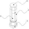
图1为本实用新型实施例提供的尿液收集装置的结构示意图;1 is a schematic structural diagram of a urine collection device provided by an embodiment of the present invention;
图2为本实用新型实施例提供的尿液收集装置剖面的结构示意图;2 is a schematic structural diagram of a cross-section of a urine collection device provided by an embodiment of the present utility model;
图3为本实用新型实施例提供的底盖组件的结构示意图;3 is a schematic structural diagram of a bottom cover assembly provided by an embodiment of the present invention;
图4为本实用新型实施例提供的抽取组件的结构示意图。FIG. 4 is a schematic structural diagram of an extraction component provided by an embodiment of the present invention.
主要附图标记:Main reference signs:
1、透明外壳;2、抽取组件;3、底盖组件;4、试管;201、拉盖;202、连杆;203、排气盘;204、试管槽;205、连通管槽;301、底盖;302、放置槽;303、进液槽口;304、连通管;305、隔膜;306、连通槽口。1. Transparent shell; 2. Extraction assembly; 3. Bottom cover assembly; 4. Test tube; 201, Pull cover; 202, Connecting rod; 203, Exhaust tray; 204, Test tube groove; 205, Connecting pipe groove; cover; 302, placing slot; 303, liquid inlet slot; 304, communicating tube; 305, diaphragm; 306, communicating slot.
具体实施方式Detailed ways
为了使本领域的技术人员更好地理解本实用新型的技术方案,下面将结合附图对本实用新型作进一步的详细介绍。In order to make those skilled in the art better understand the technical solutions of the present invention, the present invention will be further described in detail below with reference to the accompanying drawings.
如图1-4所示,一种泌尿外科用尿液收集装置,包括固定试管4的底盖组件3和卡接于试管4外壁的抽取组件2,底盖组件3的顶部设置有阻隔机构,底盖组件3的内部设置有连通器机构,连通器机构包括进液槽口303和连通管304,进液槽口303连接于试管4和连通管304,抽取组件2被装配用于驱使尿液进入试管4和连通管304。As shown in Figures 1-4, a urine collection device for urology includes a
该泌尿外科用尿液收集装置主要目的是为了通过底盖组件3内部进液槽口303与连通管304相接构成连通器的原理,使流入试管4内的尿液和连通管304内部的尿液保持同样的高度,且连通管304高于试管4,使得尿液不会超过连通管304漏出;还通过连通管304顶部设置的若干数量的隔膜305,使得底盖组件3翻转过来后,不会使连通管304内部的尿液漏出,保证其卫生安全。The main purpose of the urine collection device for urology is to connect the
本实用提供的技术方案中,由图1、图2和图3可知,底盖组件3包括底盖301,且底盖301的内部卡接设置有透明外壳1,可时刻观察到内部的尿液收集的情况,底盖301的内部开设有放置槽302,且放置槽302的底部还居中开设有进液槽口303,试管4可卡接于放置槽302的内部,且试管4的开口处朝下放置,使进液槽口303相接于试管4的内部,使得尿液可从进液槽口303进入试管4的内部,进行收集工作。In the technical solution provided by the present application, it can be seen from FIG. 1 , FIG. 2 and FIG. 3 that the
再者,放置槽302的外部设置有连通管304,且连通管304的高度高于试管4的高度,且阻隔机构设置于连通管304的顶部,包括呈圆周阵列分布的隔膜305,若干数量的隔膜305构成类似心脏瓣膜的结构,与自行车气门芯的原理相同,可使气体流动,而防止内部的尿液漏出,底盖301的内部设置有连通槽口306,连通槽口306用于连接进液槽口303和连通管304,使进液槽口303连接的试管4和连通管304构成连通器,使得两者内部进入的尿液高度相通,且连通管304的高度高于试管4,使得连通管304内部的尿液不会超出连通管304的高度,则不会漏出。Furthermore, a
本实用提供的技术方案中,由图1和图4可知,抽取组件2包括拉盖201,且拉盖201位于透明外壳1的顶部,拉盖201的底部对称设置有连杆202,连杆202穿过透明外壳1的顶部伸入透明外壳1的内部,连杆202的底部设置有排气盘203,排气盘203外壁贴合于透明外壳1的内壁,使得将拉盖201向上拉动时,使得内部的空气被排出,在通过大气压的作用,使尿液被挤入试管4和连通管304的内部。In the technical solution provided by the present application, as can be seen from FIG. 1 and FIG. 4 , the
再者,排气盘203的顶部居中开设有试管槽204,用于卡接试管4,且试管槽204的外部开设有连通管槽205,用于卡接连通管304,使得排气盘203可位于透明外壳1的内部进行竖直往复运动。Furthermore, the top of the
本实用提供的技术方案中,由图1可知,透明外壳1为透明塑料一体制成。In the technical solution provided by the present application, as can be seen from FIG. 1 , the transparent casing 1 is integrally made of transparent plastic.
工作原理:首先将试管4倒扣卡接于放置槽302的内部,再将抽取组件2卡接于试管4和连通管304的外部,此时抽取组件2位于最低端,之后合上透明外壳1;Working principle: First, the
然后将底盖组件3底部的进液槽口303伸入尿液杯的内部,通过拉动拉盖201,使排气盘203上升,将透明外壳1内部的空气排出,通过大气压的原理,使尿液杯内部的尿液被大气压入试管4和连通管304的内部;Then, the
且由于试管4和连通管304通过内部的连通槽口306相接,构成连通器,使得两者内部的尿液液面等高,使尿液不会从连通管304的内部漏出;And because the
通过透明外壳1进行观察,当试管4内部的尿液足够后,将整个装置倒转取出,此时通过连通管304端部的隔膜305的配合,使得连通管304内部的尿液不会漏出,此时打开透明外壳1,取出试管4即可,最后再将连通管304内的尿液倒回尿液杯的内部。Observing through the transparent casing 1, when the urine inside the
以上只通过说明的方式描述了本实用新型的某些示范性实施例,毋庸置疑,对于本领域的普通技术人员,在不偏离本实用新型的精神和范围的情况下,可以用各种不同的方式对所描述的实施例进行修正。因此,上述附图和描述在本质上是说明性的,不应理解为对本实用新型权利要求保护范围的限制。Certain exemplary embodiments of the present invention have been described above by way of illustration only, and it goes without saying that for those of ordinary skill in the art, without departing from the spirit and scope of the present invention, various different Modifications are made to the described embodiments. Accordingly, the above drawings and descriptions are illustrative in nature and should not be construed as limiting the scope of protection of the claims of the present invention.
Claims (6)
Translated fromChinesePriority Applications (1)
| Application Number | Priority Date | Filing Date | Title |
|---|---|---|---|
| CN202122956818.9UCN216695707U (en) | 2021-11-29 | 2021-11-29 | A urine collection device for urology |
Applications Claiming Priority (1)
| Application Number | Priority Date | Filing Date | Title |
|---|---|---|---|
| CN202122956818.9UCN216695707U (en) | 2021-11-29 | 2021-11-29 | A urine collection device for urology |
Publications (1)
| Publication Number | Publication Date |
|---|---|
| CN216695707Utrue CN216695707U (en) | 2022-06-07 |
Family
ID=81835367
Family Applications (1)
| Application Number | Title | Priority Date | Filing Date |
|---|---|---|---|
| CN202122956818.9UExpired - Fee RelatedCN216695707U (en) | 2021-11-29 | 2021-11-29 | A urine collection device for urology |
Country Status (1)
| Country | Link |
|---|---|
| CN (1) | CN216695707U (en) |
Cited By (1)
| Publication number | Priority date | Publication date | Assignee | Title |
|---|---|---|---|---|
| CN115950687A (en)* | 2023-03-13 | 2023-04-11 | 山东第一医科大学附属省立医院(山东省立医院) | A urology testing and sampling device |
- 2021
- 2021-11-29CNCN202122956818.9Upatent/CN216695707U/ennot_activeExpired - Fee Related
Cited By (2)
| Publication number | Priority date | Publication date | Assignee | Title |
|---|---|---|---|---|
| CN115950687A (en)* | 2023-03-13 | 2023-04-11 | 山东第一医科大学附属省立医院(山东省立医院) | A urology testing and sampling device |
| CN115950687B (en)* | 2023-03-13 | 2023-09-29 | 山东第一医科大学附属省立医院(山东省立医院) | Urological testing and sampling equipment |
Similar Documents
| Publication | Publication Date | Title |
|---|---|---|
| CN216695707U (en) | A urine collection device for urology | |
| CN211096367U (en) | Drainage decompression sleeve device for intestinal obstruction | |
| CN110595842A (en) | Urine collection device for medical examination | |
| CN211862865U (en) | Tumor pathology specimen collecting device | |
| CN204765666U (en) | Animal high fat of blood blood sampling device | |
| CN209996367U (en) | Urine collector for clinical examination | |
| CN219699970U (en) | Saliva collection and preservation device | |
| CN208611418U (en) | A medical drainage volume measuring cup | |
| CN216535300U (en) | High-efficient painless blood sampling device of centre gripping formula annular micropin sword tesla valve | |
| CN208000228U (en) | A laboratory urine collection device | |
| CN205952706U (en) | Body fluid selective examination storage device of division of endocrinology | |
| CN211934119U (en) | Urine collector for women | |
| CN213364330U (en) | Division of endocrinology's urine sampling device | |
| CN209387350U (en) | A kind of disposable liquid trap of hospital's urine examination | |
| CN211270863U (en) | Novel clinical laboratory's collection urine ware | |
| CN204649474U (en) | A kind of microbiological analysis sampler | |
| CN212913262U (en) | Placer is collected to tumour sample | |
| CN217723551U (en) | Disposable quantitative urine portable collector | |
| CN213883285U (en) | Sampling device for urological department | |
| CN214969686U (en) | A pleural fluid drainage device | |
| CN109297768A (en) | Disposable liquid collector for hospital urine test | |
| CN219798859U (en) | Urine retaining and taking device | |
| CN221750561U (en) | Urine collection device | |
| CN206728895U (en) | One kind is used for fish-egg, fry siphon and collection device | |
| CN210154869U (en) | Mid-section urine specimen collection device for indwelling urinary catheter |
Legal Events
| Date | Code | Title | Description |
|---|---|---|---|
| GR01 | Patent grant | ||
| GR01 | Patent grant | ||
| CF01 | Termination of patent right due to non-payment of annual fee | Granted publication date:20220607 | |
| CF01 | Termination of patent right due to non-payment of annual fee |