CN216646959U - Headband adjusting mechanism and electronic device - Google Patents
Headband adjusting mechanism and electronic deviceDownload PDFInfo
- Publication number
- CN216646959U CN216646959UCN202122019050.2UCN202122019050UCN216646959UCN 216646959 UCN216646959 UCN 216646959UCN 202122019050 UCN202122019050 UCN 202122019050UCN 216646959 UCN216646959 UCN 216646959U
- Authority
- CN
- China
- Prior art keywords
- headband
- gear portion
- actuating member
- knob
- adjustment mechanism
- Prior art date
- Legal status (The legal status is an assumption and is not a legal conclusion. Google has not performed a legal analysis and makes no representation as to the accuracy of the status listed.)
- Active
Links
- 230000007774longtermEffects0.000abstractdescription5
- 230000000694effectsEffects0.000abstractdescription3
- 238000010586diagramMethods0.000description3
- 230000003190augmentative effectEffects0.000description2
- 238000000034methodMethods0.000description2
- 238000012986modificationMethods0.000description1
- 230000004048modificationEffects0.000description1
- 230000000149penetrating effectEffects0.000description1
- 125000006850spacer groupChemical group0.000description1
Images


Landscapes
- Helmets And Other Head Coverings (AREA)
Abstract
Description
Translated fromChinese技术领域technical field
本实用新型涉及一种调整机构,尤其涉及一种头带调整机构与包括其的电子装置。The utility model relates to an adjustment mechanism, in particular to a headband adjustment mechanism and an electronic device comprising the same.
背景技术Background technique
随着科技的进步,头戴式装置不断地推陈出新,无论是虚拟现实、增强现实或混合现实等沉浸式体验的效果越来越优异,因此也逐渐广泛地导入游戏、媒体、远端临场、零售、教育、医疗等各种不同应用。尤其,近年来远距离学习或工作逐渐成为主流,更大幅增加了对头戴式装置的需求。With the advancement of technology, head-mounted devices are constantly being introduced, and the effects of immersive experiences such as virtual reality, augmented reality, or mixed reality are getting better and better, so they are gradually being widely introduced into games, media, telepresence, retail , education, medical and other different applications. In particular, in recent years, distance learning or work has gradually become mainstream, which has greatly increased the demand for head-mounted devices.
通常,为了适应各种不同的头形尺寸,头戴式装置一般在头戴处设有一调节装置,以便于使用者自行调整头带至所需的长度。然而,目前市面上大部分调整头带的装置的尺寸偏大,与之配合的头带宽度也较宽,不仅增加整体装置的尺寸与重量而容易造成长时间使用的负担与不适感,也会使整个装置外观显得笨重而影响消费者购买的欲望。Generally, in order to adapt to various head shapes, the head-mounted device is generally provided with an adjustment device at the head-mounted position, so that the user can adjust the headband to a desired length. However, most of the devices for adjusting the headband on the market are large in size, and the width of the headband is also wider, which not only increases the size and weight of the overall device, but also easily causes the burden and discomfort of long-term use. It makes the appearance of the whole device appear bulky and affects the desire of consumers to buy.
因此,需要提供一种头带调整机构以及包括其的电子装置来解决上述问题。Therefore, there is a need to provide a headband adjustment mechanism and an electronic device including the same to solve the above problems.
实用新型内容Utility model content
有鉴于此,本实用新型提供一种头带调整机构与包括其的电子装置,有助于使整体尺寸轻量化,以达到提供轻盈与舒适的穿戴体验及降低长时间使用的负担与不适感等目的。In view of this, the present invention provides a headband adjustment mechanism and an electronic device including the same, which helps to reduce the overall size, so as to provide a light and comfortable wearing experience and reduce the burden and discomfort of long-term use. Purpose.
根据本实用新型的一实施例所公开的一种头带调整机构,头带调整机构适于调整至少两个头带,包括一外壳以及一调整旋钮。外壳适于供头带穿设。调整旋钮可转动地设置于外壳,且至少部分地容置于外壳当中。调整旋钮用于收紧和放松头带。According to a headband adjustment mechanism disclosed in an embodiment of the present invention, the headband adjustment mechanism is suitable for adjusting at least two headbands, and includes a casing and an adjustment knob. The shell is suitable for the headgear to pass through. The adjustment knob is rotatably disposed in the casing and at least partially accommodated in the casing. The adjustment knob is used to tighten and loosen the headband.
根据本实用新型的一实施例所公开的一种电子装置,电子装置包括至少两个头带以及一头带调整机构。头带调整机构包括一外壳以及一调整旋钮。外壳适于供头带穿设。调整旋钮可转动地设置于外壳,且至少部分地容置于外壳当中。调整旋钮用于收紧和放松头带。According to an electronic device disclosed in an embodiment of the present invention, the electronic device includes at least two headbands and a headband adjustment mechanism. The headband adjustment mechanism includes a casing and an adjustment knob. The shell is suitable for the headgear to pass through. The adjustment knob is rotatably disposed in the casing and at least partially accommodated in the casing. The adjustment knob is used to tighten and loosen the headband.
应用本实用新型实施例的头带调整机构与电子装置,由于其用于收紧和放松头带的调整旋钮部分地容置于外壳当中,从而有助于降低头带调整机构的整体厚度,藉此,有助于使应用此头带调整机构的电子装置的整体尺寸轻量化,达到提供轻盈与舒适的穿戴体验及降低长时间使用的负担与不适感等效果。The headband adjustment mechanism and the electronic device applying the embodiments of the present invention, because the adjustment knob for tightening and loosening the headband is partially accommodated in the casing, thereby helping to reduce the overall thickness of the headband adjustment mechanism, thereby reducing the overall thickness of the headband adjustment mechanism. Therefore, the overall size of the electronic device to which the headband adjustment mechanism is applied can be reduced in size, so as to provide a light and comfortable wearing experience, and reduce the burden and discomfort of long-term use.
以上关于本实用新型公开内容的说明及以下的实施方式的说明,是用以示范与解释本实用新型的精神与原理,并且提供本实用新型的权利要求书更进一步的解释。The above description of the disclosure of the present invention and the description of the following embodiments are used to demonstrate and explain the spirit and principle of the present invention, and provide further explanation for the claims of the present invention.
附图说明Description of drawings
图1显示应用有本实用新型的一实施例的头带调整机构的电子装置的局部立体示意图。FIG. 1 shows a partial perspective view of an electronic device to which a headband adjustment mechanism according to an embodiment of the present invention is applied.
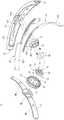
图2显示本实用新型的一实施例的头带调整机构的分解示意图。FIG. 2 shows an exploded schematic view of a headband adjustment mechanism according to an embodiment of the present invention.
图3显示本实用新型的一实施例的头带调整机构的局部放大剖切示意图。FIG. 3 shows a partially enlarged cross-sectional schematic diagram of a headband adjustment mechanism according to an embodiment of the present invention.
图4显示本实用新型的一实施例的头带调整机构的局部放大平面示意图。FIG. 4 shows a partial enlarged plan view of a headband adjustment mechanism according to an embodiment of the present invention.
图5~6显示本实用新型的一实施例的头带调整机构的齿轮部与头带在不同视角的啮合示意图。FIGS. 5-6 are schematic diagrams showing the meshing of the gear portion of the headband adjustment mechanism and the headband at different viewing angles according to an embodiment of the present invention.
图7显示本实用新型的一实施例的头带调整机构的操作示意图。FIG. 7 shows a schematic view of the operation of the headband adjustment mechanism according to an embodiment of the present invention.
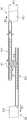
图8显示本实用新型的另一实施例的头带调整机构的分解示意图。FIG. 8 shows an exploded schematic view of a headband adjustment mechanism according to another embodiment of the present invention.
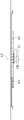
图9显示图8的头带调整机构的调整旋钮、致动件与止挡件的分解示意图。FIG. 9 shows an exploded schematic view of an adjustment knob, an actuating member and a stopper of the headband adjustment mechanism of FIG. 8 .
图10显示图8的头带调整机构的局部放大俯视示意图。FIG. 10 shows a partially enlarged top view of the headband adjustment mechanism of FIG. 8 .
图11显示图8的头带调整机构的局部放大侧剖示意图。FIG. 11 is a partially enlarged schematic side sectional view of the headband adjustment mechanism of FIG. 8 .
主要组件符号说明:Explanation of main component symbols:
1、1' 头带调整机构1. 1' headband adjustment mechanism
9 电子装置9 Electronics
10 外壳10 shell
11 第一壳件11 The first shell
12 第二壳件12 Second shell
20、20' 调整旋钮20, 20' adjustment knob
21 组装柱21 Assembling the column
22 抵接柱22 Abutment post
30、30' 致动件30, 30' Actuator
31 弹性棘爪31 Elastic pawl
32 齿轮部32 gear section
33 组装孔33 Assembly holes
35 第一齿轮部35 First gear part
36 第二齿轮部36 Second gear section
40、40' 止挡件40, 40' stop
41 内棘轮41 Inner ratchet
42 穿孔42 perforation
43 弹片43 Shrapnel
50 垫片50 Spacers
81~82 头带81~82 Headband
121 容置空间121 accommodating space
122 轴柱122 Axle Post
811、821 齿条部811, 821 Rack part
812、822 带部812, 822 belt
A1、B1、B2 箭头A1, B1, B2 Arrows
AX 转轴AX reel
O 开口O opening
S 容置槽S Reservoir
W1、W2 宽度W1, W2 width
具体实施方式Detailed ways
以下将以实施方式详细叙述本实用新型的详细特征以及优点,其内容足以使任何本领域的技术人员了解本实用新型的技术内容并据以实施,但非以任何观点限制本实用新型的范畴。The detailed features and advantages of the present invention will be described in detail below by means of embodiments, the content of which is sufficient to enable any person skilled in the art to understand the technical content of the present invention and implement accordingly, but does not limit the scope of the present invention in any point of view.
以下实施例将搭配附图进行说明,为达图面整洁的目的,一些公知惯用的结构与元件在附图可能会以简单示意的方式绘示。并且,附图中部分的特征可能会略为放大或改变其比例或尺寸,以达到便于理解与观看本实用新型的技术特征的目的,但这并非用于限定本实用新型。此外,为便于观看,部分附图中的某些结构线可能以虚线表示。The following embodiments will be described in conjunction with the accompanying drawings. For the purpose of neat and tidy drawings, some well-known and conventional structures and elements may be shown in a simple and schematic manner in the accompanying drawings. In addition, some features in the drawings may be slightly enlarged or their proportions or dimensions are changed to achieve the purpose of facilitating the understanding and viewing of the technical features of the present invention, but this is not intended to limit the present invention. Additionally, some of the structural lines in some of the drawings may be represented by dashed lines for ease of viewing.
此外,下文中可能会使用“端”、“部”、“部分”、“区域”、“处”等术语来描述特定元件与结构或是其上或其之间的特定技术特征,但这些元件与结构并不受这些术语所限制。以下文中也可能使用诸如“实质上”、“约”以及“大致上”等术语,用于描述所修饰的情况或事件可能存在的合理或可接受的偏差量,但仍可达到所预期的结果。In addition, terms such as "end", "portion", "portion", "region", "at" and the like may be used hereinafter to describe specific elements and structures or specific technical features on or between them, but these elements AND structures are not limited by these terms. Hereinafter, terms such as "substantially", "about" and "substantially" may also be used to describe a reasonable or acceptable amount of deviation from the circumstances or events that may be modified and still achieve the desired result .
另外,下文中可能使用“至少一”来描述所指元件的数量,但除非另有明确说明,其不应仅限于数量为“仅有一”的情况。下文中也可能使用“和/或”的术语,其应被理解为包括所列出项目中的任一者及一者或多者的所有组合。Additionally, hereinafter, "at least one" may be used to describe the quantity of a referenced element, but unless expressly stated otherwise, it should not be limited to "only one". The term "and/or" may also be used hereinafter, which should be understood to include any and all combinations of one or more of the listed items.
首先,请参阅图1~4,图1显示应用有本实用新型的一实施例的头带调整机构1的电子装置9的局部立体示意图,图2显示头带调整机构1的分解示意图,图3显示头带调整机构1的局部放大剖切示意图,而图4显示头带调整机构1的局部放大平面示意图。电子装置9可包括头带调整机构1以及经由一头带81与一头带82衔接的一多媒体播放模块(未绘示),以构成一种适于穿戴于头部的头戴式显示器。所述的多媒体播放模块可以但不限于是能提供增强现实、虚拟现实或混合现实等体验的任何现有的合适显示装置。头带调整机构1可用于调整头带81与头带82所露出的长度(或者说,调整头带81与头带82对于头部的松紧程度),以使电子装置9能适应于各种不同的头形尺寸,详细说明如下。First, please refer to FIGS. 1 to 4 . FIG. 1 shows a partial perspective view of an
在本实施例中,头带调整机构1可包括一外壳10、一调整旋钮20、一致动件30以及一止挡件40。大致上,调整旋钮20、致动件30与止挡件40均容置于外壳10,惟调整旋钮20的部分裸露于外壳10外(或者说,调整旋钮20至少部分容置于外壳10当中)。藉由调整旋钮20与致动件30相连动,可让使用者藉由操作调整旋钮20来调整穿入外壳10的头带81与头带82的长度(即调整头带81与头带82所露出的长度)。并且,藉由致动件30与止挡件40彼此配合,可用于定位并止挡致动件30,从而维持头带81与头带82在当下的位置。In this embodiment, the
具体来说,外壳10可包括一第一壳件11以及一第二壳件12,第一壳件11与第二壳件12可由任何合适的材质所构成,且可由任何合适的方式相固定,第二壳件12可定义出一容置空间121,以用于收容调整旋钮20、致动件30、止挡件40以及至少部分的头带81与头带82。此外,外壳10的第二壳件12还可具有两个开口O,分别连通于容置空间121的相对两端,以分别用于供头带81与头带82穿入容置空间121。Specifically, the
进一步来看,在本实施例中,头带81可以但不限于是一体成型的带状或条状结构,且可包括彼此相连的一齿条部811以及一带部812,齿条部811的宽度小于带部812,是为头带81上用于啮合于头带调整机构1的部分,而带部812的宽度较宽,适于裸露于头带调整机构1之外,以用于贴附于头部并确保穿戴舒适度。头带82的结构可实质上相同或相似于头带81,如图所示,头带82可以但不限于是一体成型的带状或条状结构,且可包括彼此相连的一齿条部821以及一带部822,齿条部821的宽度小于带部822,是为头带82上用于啮合于头带调整机构1的部分,而带部822的宽度较宽,适于裸露于头带调整机构1之外,以用于贴附于头部并确保穿戴舒适度。头带81的带部812与头带82的带部822可分别穿设于外壳10的开口O,以令齿条部811与齿条部821进入容置空间121而啮合于头带调整机构1的致动件30,从而可受致动件30的作用而相对头带调整机构1活动。Looking further, in this embodiment, the
进一步来说,使用者可藉由往特定方向旋转调整旋钮20的方式致动致动件30,以令头带81与头带82相对头带调整机构1往特定方向活动而逐渐减少或增加头带81与头带82裸露于外的长度,即调整头带81与头带82的松紧度以适应于所需的头围尺寸。Further, the user can actuate the
为此,在本实施例中,外壳10的第二壳件12可突设有一轴柱122,位于容置空间121内且沿一转轴AX向内延伸突出,调整旋钮20可转动地套设于轴柱122,从而可绕着转轴AX相对外壳10转动。此外,调整旋钮20朝向第二壳件12的表面可具有一容置槽S,可用于容置至少部分的致动件30与止挡件40,并且,调整旋钮20还可具有至少一组装柱21以及至少一抵接柱22,突设于调整旋钮20朝向第二壳件12的表面并位于容置槽S内,以用于连动致动件30。To this end, in the present embodiment, the
相应于此,在本实施例中,致动件30可转动地套设于轴柱122并至少部分地位于调整旋钮20的容置槽S中,从而介于调整旋钮20与第二壳件12之间。致动件30可以但不限于以任何合适的材质所一体成型的结构,且可具有至少一弹性棘爪(pawl)31、一齿轮部32以及至少一组装孔33,齿轮部32可以但不限于是任何合适的正齿轮,其可转动地套设于轴柱122并啮合于头带81的齿条部811与头带82的齿条部821之间。Correspondingly, in this embodiment, the actuating
在此,请对应图2再进一步参阅图5~6,显示头带调整机构1的齿轮部32与头带81以及头带82在不同视角的啮合示意图,齿轮部32以与头带81的齿条部811以及头带82的齿条部821在转轴AX的方向上相重叠的方式啮合,或者说,齿条部811与齿条部821的齿是自头带81与头带82的朝向调整旋钮20的容置槽S的表面突出,使得齿轮部32可以叠设于齿条部811与齿条部821的方式与其齿啮合。藉此,齿条部811与齿条部821的宽度W1可设计的较窄。并且,齿轮部32同时与宽度窄的齿条部811及齿条部821重叠配置,与之对应的带部812与带部822的宽度W2可至少减缩至一个较小的尺寸,有助于使头带81与头带82的整体宽度维持于一个相对较窄的程度。Here, please refer to FIGS. 5 to 6 further corresponding to FIG. 2 , which show the meshing schematic diagrams of the
接着,请再参阅图2~4,在本实施例中,致动件30的弹性棘爪31可摆动地衔接于齿轮部32的相异侧并往相异的方向向外延伸,因而可在受外力驱使时产生形变而相对齿轮部32摆动。致动件30的组装孔33可位于齿轮部32的相异侧,且可以但不限于是圆心落于转轴AX的弧形孔。调整旋钮20的组装柱21分别可滑移地位于组装孔33中,而调整旋钮20的抵接柱22则可活动地位于弹性棘爪31的外侧,以随着调整旋钮20往特定方向转动时挤压弹性棘爪31,从而驱使弹性棘爪31往转轴AX的方向弯曲(如后续图7所示)。弹性棘爪31的外侧是指弹性棘爪31相对远离转轴AX的一侧。Next, referring to FIGS. 2-4, in this embodiment, the
另外,在本实施例中,止挡件40套设于致动件30上并至少部分地位于调整旋钮20的容置槽S中,并且,止挡件40可以任何合适的方式固定于外壳10的第二壳件12而介于调整旋钮20与第二壳件12之间。具体来说,在本实施例中,止挡件40可以但不限于以任何合适的材质所一体成型的结构,可具有一内棘轮(ratchet)41以及一穿孔42,内棘轮41可包括以转轴AX为圆心排列成一圈的多个单向棘齿,可在致动件30的弹性棘爪31未受调整旋钮20的抵接柱22挤压时与弹性棘爪31相卡合,从而经由止挡弹性棘爪31而阻止致动件30往特定方向的转动,换句话说,弹性棘爪31可分离地卡合于内棘轮41,以在特定方向转动时受阻于内棘轮41而被维持于当下位置。穿孔42对应于转轴AX,可用以供致动件30的齿轮部32穿设,以使齿轮部32能穿过止挡件40而啮合头带81的齿条部811与头带82的齿条部821。此外,在本实施例中,头带调整机构1还可包括一垫片50,可固定于止挡件40上并夹设于致动件30与止挡件40之间,其可由任何合适的材质所构成,以适度降低致动件30转动时与止挡件40之间的摩擦力,但垫片50为选用而非用于限制本实用新型。In addition, in this embodiment, the
接着,请接着继续图4~6一并再参阅图7,以藉由头带调整机构1的操作说明使前述内容更为清楚。为了调整头带81与头带82裸露于外的长度以使其符合头围大小,例如当使用者欲调松或放松头带81与头带82,可藉由往特定方向转动调整旋钮20的方式来实现(如图示的箭头A1所示方向),藉此,调整旋钮20的组装柱21可往致动件30的组装孔33的另一端滑移,同时,调整旋钮20的抵接柱22将随着调整旋钮20的转动推挤致动件30的弹性棘爪31,以使弹性棘爪31往转轴AX的方向挤压变形而脱离止挡件40的内棘轮41。也就是说,此时致动件30不受到止挡件40的限制,而可受到调整旋钮20的组装柱21及抵接柱22的推动往相同方向(如图示的箭头A1所示方向)转动。并且,致动件30的齿轮部32也将一并受到调整旋钮20的驱驶往箭头A1所示方向转动,从而可将与之啮合的齿条部811与齿条部821往相对远离的方向驱动(如箭头B1与箭头B2所示方向),使得头带81的带部812与头带82的带部822往头带调整机构1的外壳10外部伸出更多,达到增加头带81与头带82裸露于外的长度而放松头带81与头带82的目的。Next, please continue with FIGS. 4 to 6 and refer to FIG. 7 again, so as to make the foregoing content more clear through the operation description of the
当头带81与头带82调整至所需的长度时,使用者可松开调整旋钮20或略为回转调整旋钮20,使得调整旋钮20的抵接柱22脱离致动件30的弹性棘爪31,届时,弹性棘爪31自动弹性复位而回到卡合止挡件40的内棘轮41的状态,且调整旋钮20的组装柱21实质上仍位于致动件30的组装孔33的其中一端处。藉此,若头带81与头带82在穿戴或其他原因受到向外拉动的拉力时,由于内棘轮41已经由止挡弹性棘爪31止挡住致动件30,因此头带81与头带82无法驱使致动件30往箭头A1的方向转动,也因而无法往箭头B1与B2的方向移动,也就是说,藉由止挡件40对致动件30的限制,可有效防止头带81与头带82调整定位后非预期地松脱。并且,由于调整旋钮20的组装柱21位于致动件30的组装孔33的其中一端处,因此,头带81与头带82在穿戴或其他原因受到使彼此相向活动的外力时,组装柱21可经由止挡组装孔33的一端以阻止致动件30往相反于箭头A1所示的方向的转动,也就是说,藉由组装柱21对致动件30的限制,可有效防止头带81与头带82调整定位后非预期地往收紧的方向移动。由此可知,除非操作调整旋钮20,否则致动件30将不会受到齿条部811与齿条部821的影响而脱离当下的位置,以确保头带81与头带82的松紧调整定位后不会非预期移动的效果。When the
另一方面,当欲缩短头带81与头带82裸露于外的长度时(或者说,欲收紧头带81与头带82时),使用者只需要将调整旋钮20往相反于前述箭头A1的方向转动即可实现,可理解地是,调整旋钮20的组装柱21将往致动件30的组装孔33的一端推抵,从而一并使致动件30往相同方向转动,此时,内棘轮41的单向棘齿的走向设计允许致动件30的弹性棘爪31在其上滑动,因此致动件30在此方向的转动不会受到内棘轮41止挡,在此情况下,致动件30的齿轮部32则可受到调整旋钮20的驱使也一并往相反于前述箭头A1的方向转动,从而使得头带81的带部812与头带82的带部822往头带调整机构1的外壳10内部收纳,达到减少头带81与头带82裸露于外的长度而收紧头带81与头带82的目的。On the other hand, when the exposed length of the
据此可知,藉由调整旋钮20、致动件30、止挡件40的搭配,使用者可藉由顺时针或逆时针转动调整旋钮20的方式来收紧和放松头带81与头带82的目的,但同时又可避免头带81与头带82在没有操作调整旋钮20时非预期地移动。From this, it can be seen that with the matching of the
并且,由于致动件30与止挡件40可均容置于调整旋钮20的容置槽S,换句话说,头带调整机构1内用于致动头带81与头带82与防止头带81与头带82非预期移动的构件可藏于调整旋钮20内部,从而有助于降低头带调整机构1的整体厚度。Moreover, since the
同时,致动件30的齿轮部32可以叠设于齿条部811与齿条部821朝向调整旋钮20的容置槽S的表面的方式与其之啮合,因此齿条部811与齿条部821的宽度W1可设计的较窄,以使得分别与齿条部811以及齿条部821相连的带部812与带部822的宽度W2可至少减缩至一个较小的尺寸,从而有助于让头带81与头带82的整体宽度维持于一个相对较窄的程度,进而有助于使装置整体更轻量化。At the same time, the
相较于传统头带调整旋钮外置在壳体之外的设计来说,本实施例的调整旋钮20至少部分容置于外壳10,有助于维持整体外观的一体性,且由于致动件30与止挡件40藏于调整旋钮20内,因而可在薄化头带调整机构1整体厚度的同时让调整旋钮20裸露于外的部分具有一定程度的宽度,以便于使用者操作。Compared with the traditional design in which the adjustment knob of the headband is externally placed outside the casing, the
以上仅是本实用新型其中一实施例,但本实用新型并非以此为限。例如请参阅图8~11,图8显示本实用新型的另一实施例的头带调整机构1'的分解示意图,图9显示头带调整机构1'的调整旋钮20'、致动件30'与止挡件40'的分解示意图,图10显示头带调整机构1'的局部放大俯视示意图,而图11显示头带调整机构1'的局部放大侧剖示意图。需先说明的是,为达简要说明的目的,在此仅说明本实施例与前述实施例的差异部分,相似或相同的内容可经由参酌前述相应内容获得理解,且相同标号可用以表示相同元件或结构。The above is only one embodiment of the present invention, but the present invention is not limited thereto. For example, please refer to FIGS. 8-11 . FIG. 8 shows an exploded schematic view of a
在本实施例中,头带调整机构1'可包括的致动件30'可一体成形于调整旋钮20'上,致动件30'可包括一第一齿轮部35以及一第二齿轮部36,可沿转轴AX依序叠设于调整旋钮20'朝向第二壳件12的一侧,如图所示,第二齿轮部36可经由第一齿轮部35连接于调整旋钮20'。第二齿轮部36可相同或相似于前述实施例的齿轮部32,为致动件30'上用于啮合头带81的齿条部811与头带82的齿条部821的部分。第一齿轮部35则用于与止挡件40'配合,以达到定位与止挡头带81与头带82活动的目的。In this embodiment, the actuating
详细来说,在本实施例中,致动件30'的第一齿轮部35可以但不限于是任何合适的正齿轮,止挡件40'可包括至少一弹片43,可用于卡合于第一齿轮部35的齿槽。藉此,在未操作调整旋钮20'时,致动件30'可经由第一齿轮部35卡合止挡件40'的弹片43而固定于当下位置,从而可经由第二齿轮部36将头带81与头带82固定于当下的松紧度。但当欲调松或调紧头带81与头带82时,只需要顺时针或逆时针适度施力转动调整旋钮20'即可,在此过程中,调整旋钮20'可经由旋转致动件30'的第一齿轮部35以驱使止挡件40'的弹片43弯曲变形而退出第一齿轮部35的齿槽,藉此,致动件30'得以随着调整旋钮20'往所需的方向转动,从而令其第二齿轮部36往所需方向驱动头带81与头带82。据此可知,藉由调整旋钮20'、致动件30'、止挡件40'的搭配,使用者同样可藉由顺时针或逆时针转动调整旋钮20'的方式来达到收紧和放松头带81与头带82的目的,且同时又可避免头带81与头带82在没有操作调整旋钮20'时非预期地活动。In detail, in this embodiment, the
综上所述,根据本实用新型实施例所公开的头带调整机构,由于其用于啮合驱动头带的致动件以及用于止挡定位致动件的止挡件可均容置于调整旋钮的容置槽而藏于调整旋钮内部,从而有助于降低头带调整机构的整体厚度,藉此,有助于使应用此头带调整机构的电子装置的整体尺寸轻量化,达到提供轻盈与舒适的穿戴体验及降低长时间使用的负担与不适感等效果。To sum up, according to the headband adjustment mechanism disclosed in the embodiments of the present invention, the actuator for engaging and driving the headband and the stopper for stopping the positioning actuator can both be accommodated in the adjustment mechanism. The accommodating groove of the knob is hidden inside the adjustment knob, thereby helping to reduce the overall thickness of the headband adjustment mechanism, thereby helping to reduce the overall size of the electronic device to which the headband adjustment mechanism is applied, so as to provide lightness And comfortable wearing experience and reduce the burden and discomfort of long-term use.
虽然本实用新型以前述的实施例公开如上,然而其并非用以限定本实用新型。本领域的技术人员,在不脱离本实用新型的精神和范围的情况下,所作的更动与润饰,均属本实用新型的专利保护范围。关于本实用新型所界定的保护范围请参考所附的权利要求书的范围。Although the present invention is disclosed in the foregoing embodiments, it is not intended to limit the present invention. Changes and modifications made by those skilled in the art without departing from the spirit and scope of the present invention are within the scope of patent protection of the present invention. Regarding the protection scope defined by the present invention, please refer to the scope of the appended claims.
Claims (20)
Applications Claiming Priority (2)
| Application Number | Priority Date | Filing Date | Title |
|---|---|---|---|
| TW110209140UTWM621057U (en) | 2021-08-03 | 2021-08-03 | Headband adjusting mechanism and electronic device |
| TW110209140 | 2021-08-03 |
Publications (1)
| Publication Number | Publication Date |
|---|---|
| CN216646959Utrue CN216646959U (en) | 2022-05-31 |
Family
ID=80680423
Family Applications (1)
| Application Number | Title | Priority Date | Filing Date |
|---|---|---|---|
| CN202122019050.2UActiveCN216646959U (en) | 2021-08-03 | 2021-08-24 | Headband adjusting mechanism and electronic device |
Country Status (2)
| Country | Link |
|---|---|
| CN (1) | CN216646959U (en) |
| TW (1) | TWM621057U (en) |
Cited By (1)
| Publication number | Priority date | Publication date | Assignee | Title |
|---|---|---|---|---|
| CN114938483A (en)* | 2022-05-18 | 2022-08-23 | 头领科技(昆山)有限公司 | Human engineering headset |
Families Citing this family (1)
| Publication number | Priority date | Publication date | Assignee | Title |
|---|---|---|---|---|
| TWI803183B (en)* | 2022-02-09 | 2023-05-21 | 和碩聯合科技股份有限公司 | Adjustment device |
- 2021
- 2021-08-03TWTW110209140Upatent/TWM621057U/enunknown
- 2021-08-24CNCN202122019050.2Upatent/CN216646959U/enactiveActive
Cited By (1)
| Publication number | Priority date | Publication date | Assignee | Title |
|---|---|---|---|---|
| CN114938483A (en)* | 2022-05-18 | 2022-08-23 | 头领科技(昆山)有限公司 | Human engineering headset |
Also Published As
| Publication number | Publication date |
|---|---|
| TWM621057U (en) | 2021-12-11 |
Similar Documents
| Publication | Publication Date | Title |
|---|---|---|
| CN216646959U (en) | Headband adjusting mechanism and electronic device | |
| US12000459B2 (en) | Adjustment device switchable between a rotatable state or a locked state | |
| US20210333558A1 (en) | Head-mounted resilient auxiliary locking mechanism | |
| TWI626473B (en) | Head-mounted display | |
| WO2018086236A1 (en) | Adjustable headgear fastening mechanism | |
| TW202024722A (en) | Headset electronic device and headband adjustment structure thereof | |
| CN111846339B (en) | Fastening device | |
| US20170369267A1 (en) | Horizontal-pull coating film transferring tool | |
| KR20240017766A (en) | Fastening device | |
| CN107219630A (en) | A kind of adjusting means, adjustable bandage and wearable device | |
| JP3101908B2 (en) | Size adjustment band | |
| US12092832B2 (en) | Device for adjusting degree of tightness and head-mounted display including the same | |
| CN217065531U (en) | Elasticity adjustment device and head mounted display device including the same | |
| US20210221275A1 (en) | Wheelchair fastening device | |
| TWI682195B (en) | Head-mounted display | |
| CN110297326A (en) | Adjustment mechanism and head-mounted display apparatus | |
| TWI858525B (en) | Head-mounted device | |
| TWI765197B (en) | Head-mounted device and strap structure thereof | |
| CN115981006B (en) | Headband adjusting device and head-mounted equipment | |
| CN116300108A (en) | Headband adjustment device and head-mounted display device | |
| CN207334190U (en) | A kind of regulating device, adjustable bandage and wearable device | |
| CN113504649A (en) | Adjustable headband and head-mounted equipment | |
| CN207674086U (en) | A kind of regulating device, adjustable bandage and wearable device | |
| TWI695998B (en) | Adjusting device | |
| CN206818981U (en) | An adjustment mechanism, an adjustable strap and a wearable device |
Legal Events
| Date | Code | Title | Description |
|---|---|---|---|
| GR01 | Patent grant | ||
| GR01 | Patent grant |