CN216600155U - An intelligent classroom lighting control system based on ultrasonic sensor - Google Patents
An intelligent classroom lighting control system based on ultrasonic sensorDownload PDFInfo
- Publication number
- CN216600155U CN216600155UCN202123428223.2UCN202123428223UCN216600155UCN 216600155 UCN216600155 UCN 216600155UCN 202123428223 UCN202123428223 UCN 202123428223UCN 216600155 UCN216600155 UCN 216600155U
- Authority
- CN
- China
- Prior art keywords
- module
- ultrasonic
- circuit
- chip microcomputer
- control module
- Prior art date
- Legal status (The legal status is an assumption and is not a legal conclusion. Google has not performed a legal analysis and makes no representation as to the accuracy of the status listed.)
- Active
Links
Images


Classifications
- Y—GENERAL TAGGING OF NEW TECHNOLOGICAL DEVELOPMENTS; GENERAL TAGGING OF CROSS-SECTIONAL TECHNOLOGIES SPANNING OVER SEVERAL SECTIONS OF THE IPC; TECHNICAL SUBJECTS COVERED BY FORMER USPC CROSS-REFERENCE ART COLLECTIONS [XRACs] AND DIGESTS
- Y02—TECHNOLOGIES OR APPLICATIONS FOR MITIGATION OR ADAPTATION AGAINST CLIMATE CHANGE
- Y02B—CLIMATE CHANGE MITIGATION TECHNOLOGIES RELATED TO BUILDINGS, e.g. HOUSING, HOUSE APPLIANCES OR RELATED END-USER APPLICATIONS
- Y02B20/00—Energy efficient lighting technologies, e.g. halogen lamps or gas discharge lamps
- Y02B20/40—Control techniques providing energy savings, e.g. smart controller or presence detection
Landscapes
- Circuit Arrangement For Electric Light Sources In General (AREA)
Abstract
Translated fromChinese
Description
Translated fromChinese技术领域technical field
本实用新型涉及自动化控制技术领域,更具体地说,它涉及一种基于超声波传感器的智能教室灯光控制系统。The utility model relates to the technical field of automatic control, in particular to an intelligent classroom lighting control system based on ultrasonic sensors.
背景技术Background technique
科技高速发展、能源问题日益突出,以及各高校在经历快速扩招后,在校学生规模迅速增加,教学楼数量剧增,随之带来的问题就是教室电能的极大浪费以及教室公共管理的困难。教室传统的灯光控制系统主要是依靠手动开关对照明配电箱进行通断操作,或是通过串联接触器实现远距离控制。管理过程中教室传统的管理方法多依靠人工管理,但学生自觉意识较低,未能养成随手关灯的习惯;学生离开教室后管理人员未能及时关闭灯光;或者一个教室只有几个人,而教室灯光却是全部开启,这与现在提倡创建的资源节约型、环境友好型社会的理念背道而驰。此外,无法实时展现教室现有人数,会增加安全隐患,也为教室管理增加了难度。因此许多高校希望实现教室管理智能化,为能源节约及实现教室内人数统计。The rapid development of science and technology, the increasingly prominent energy problem, and the rapid increase in the number of students and the number of teaching buildings in colleges and universities after the rapid expansion of enrollment, the subsequent problems are the great waste of classroom power and the difficulty of classroom public management . The traditional lighting control system in classrooms mainly relies on manual switches to turn on and off the lighting distribution box, or realize remote control through series contactors. In the process of management, the traditional management methods of classrooms mostly rely on manual management, but students have low self-consciousness and fail to develop the habit of turning off the lights; managers fail to turn off the lights in time after students leave the classroom; or there are only a few people in a classroom, and All classroom lights are turned on, which is contrary to the concept of creating a resource-saving and environment-friendly society that is now advocated. In addition, the inability to display the current number of people in the classroom in real time will increase security risks and make classroom management more difficult. Therefore, many colleges and universities hope to realize intelligent classroom management, for energy saving and to realize the statistics of the number of people in the classroom.
实用新型内容Utility model content
为解决现有技术中的不足,本实用新型的目的是提供一种基于超声波传感器的智能教室灯光控制系统,可根据进出教室的人的数量、教室内外的光线强度变化,对教室内的照明装置的开启实现智能化控制,在保证照明要求的前提下,降低了电力浪费。In order to solve the deficiencies in the prior art, the purpose of this utility model is to provide an intelligent classroom lighting control system based on ultrasonic sensors, which can control the lighting device in the classroom according to the number of people entering and leaving the classroom and the changes in the light intensity inside and outside the classroom. The opening of the device realizes intelligent control, and reduces the waste of electricity on the premise of ensuring the lighting requirements.
本实用新型的上述技术目的是通过以下技术方案得以实现的:一种基于超声波传感器的智能教室灯光控制系统,包括光线检测模块、人体检测模块、单片机控制模块以及灯光控制模块;The above-mentioned technical purpose of the present utility model is achieved through the following technical solutions: an intelligent classroom lighting control system based on ultrasonic sensors, comprising a light detection module, a human body detection module, a single-chip control module and a lighting control module;
所述光线检测模块、人体检测模块的输出端均与单片机控制模块的输入端连接,单片机控制模块的输出端与灯光控制模块的输入端连接;The output ends of the light detection module and the human body detection module are all connected with the input end of the single-chip control module, and the output end of the single-chip control module is connected with the input end of the lighting control module;
所述光线检测模块,用于监测室内的光线强度;The light detection module is used to monitor the light intensity in the room;
所述人体检测模块,用于根据超声波传感器信号的中断次数及先后判断进出人数,并统计室内的现有人数;The human body detection module is used for judging the number of people entering and leaving the room according to the number of interruptions of the ultrasonic sensor signal and the sequence, and counts the existing number of people in the room;
所述单片机控制模块,用于在光线强度超出预设阈值时生成系统启动信号,并在系统启动信号生成后根据现有人数的分布区间生成相应的控制信号;The single-chip control module is used to generate a system startup signal when the light intensity exceeds a preset threshold, and after the system startup signal is generated, a corresponding control signal is generated according to the distribution interval of the existing population;
所述灯光控制模块,用于响应于控制信号后驱动对应数量的灯光回路启动。The lighting control module is used to drive a corresponding number of lighting circuits to start in response to the control signal.
进一步的,所述光线检测模块包括稳压电路和光强度传感器;Further, the light detection module includes a voltage regulator circuit and a light intensity sensor;
所述稳压电路采用稳压芯片XC6206,光强度传感器采用光强度数字转换芯片TSL2561;The voltage regulator circuit adopts the voltage regulator chip XC6206, and the light intensity sensor adopts the light intensity digital conversion chip TSL2561;
所述稳压芯片XC6206将单片机控制模块中第一单片机的+5V工作电压降为3.3V后为光强度数字转换芯片TSL2561供电。The voltage-stabilizing chip XC6206 reduces the +5V working voltage of the first single-chip microcomputer in the single-chip control module to 3.3V and supplies power to the light intensity digital conversion chip TSL2561.
进一步的,所述人体检测模块包括升压电路、超声波发射电路、超声波接收电路和信号转换电路;Further, the human body detection module includes a boosting circuit, an ultrasonic transmitting circuit, an ultrasonic receiving circuit and a signal conversion circuit;
所述升压电路,用于将单片机控制模块中第一单片机的+5V工作电压转为9V为超声波发射电路提供工作电压;The boosting circuit is used to convert the +5V working voltage of the first single-chip microcomputer in the single-chip control module to 9V to provide the working voltage for the ultrasonic transmitting circuit;
所述超声波发射电路,用于在工作电压9V下产生40KHz的超声波;The ultrasonic transmitting circuit is used to generate ultrasonic waves of 40KHz under the working voltage of 9V;
所述超声波接收电路,用于不断接收发射来的超声波;The ultrasonic receiving circuit is used to continuously receive the transmitted ultrasonic waves;
所述信号转换电路,用于将超声波接收电路中的模拟信号转换为数字信号后发送到第一单片机中。The signal conversion circuit is used for converting the analog signal in the ultrasonic receiving circuit into a digital signal and then sending it to the first single-chip microcomputer.
进一步的,所述所述单片机控制模块采用配置有第一单片机、电源电路、晶振电路以及复位电路的最小单片机系统,第一单片机采用STC89C52芯片。Further, the single-chip microcomputer control module adopts a minimum single-chip microcomputer system configured with a first single-chip microcomputer, a power supply circuit, a crystal oscillator circuit and a reset circuit, and the first single-chip microcomputer adopts the STC89C52 chip.
进一步的,所述灯光控制模块包括多个继电器以及与继电器一一对应的照明灯;Further, the lighting control module includes a plurality of relays and lighting lamps corresponding to the relays one-to-one;
所述继电器响应于控制信号后控制所在灯光回路中的照明灯启动亮起。In response to the control signal, the relay controls the lighting in the lighting circuit to start and light up.
进一步的,所述继电器的输入端IN通过第一开关与单片机控制模块的输出端连接。Further, the input terminal IN of the relay is connected to the output terminal of the single-chip microcomputer control module through the first switch.
进一步的,所述照明灯的一端与相应继电器的公共端COM连接,另一端通过单刀双掷开关分别与常闭端口NC、常开端口NO连接。Further, one end of the lighting lamp is connected to the common terminal COM of the corresponding relay, and the other end is respectively connected to the normally closed port NC and the normally open port NO through the SPDT switch.
进一步的,该系统还包括无线通信模块和远程终端;Further, the system also includes a wireless communication module and a remote terminal;
所述单片机控制模块通过无线通信模块与远程终端连接;The single-chip control module is connected with a remote terminal through a wireless communication module;
所述远程终端,用于对单片机控制模块输出的现有人数进行显示。The remote terminal is used to display the existing number of people output by the single-chip control module.
进一步的,所述无线通信模块采用型号为CC2530的射频模块,射频前端采用型号为C2591的射频前端芯片,CC2530的射频模块为基于ZigBee协议的无线射频终端。Further, the wireless communication module adopts a radio frequency module of model CC2530, the radio frequency front end adopts a radio frequency front end chip of model C2591, and the radio frequency module of CC2530 is a wireless radio frequency terminal based on ZigBee protocol.
进一步的,所述远程终端配置有第二单片机、通信接口模块和显示屏;Further, the remote terminal is configured with a second single-chip microcomputer, a communication interface module and a display screen;
所述通信接口模块采用RS232通信接口;The communication interface module adopts RS232 communication interface;
所述通信接口模块将第二单片机接收的现有人数传输至显示屏所在的上位机,并以显示屏进行展示。The communication interface module transmits the existing number of people received by the second single-chip microcomputer to the upper computer where the display screen is located, and displays it on the display screen.
与现有技术相比,本实用新型具有以下有益效果:Compared with the prior art, the utility model has the following beneficial effects:
1、本实用新型提出的一种基于超声波传感器的智能教室灯光控制系统,可根据进出教室的人的数量、教室内外的光线强度变化,对教室内的照明装置的开启实现智能化控制,在保证照明要求的前提下,降低了电力浪费;1. An intelligent classroom lighting control system based on ultrasonic sensors proposed by the present utility model can realize intelligent control of the opening of lighting devices in the classroom according to the number of people entering and leaving the classroom and the changes in the light intensity inside and outside the classroom. Under the premise of lighting requirements, power waste is reduced;
2、本实用新型分为手动模式和自动模式;手动模式下,工作人员通过第一开关手动控制灯光;自动模式下,该系统通过光线强度传感器监测室内光线强度,并通过人体检测模块中的超声波传感器信号中断次数及先后,判断进出人数并统计室内现有人数,以及第一单片机根据室内光照强度以及人员数判调节室内点亮的灯带数目;2. The utility model is divided into a manual mode and an automatic mode; in the manual mode, the staff manually controls the light through the first switch; in the automatic mode, the system monitors the indoor light intensity through the light intensity sensor, and passes the ultrasonic wave in the human body detection module. The number and sequence of sensor signal interruptions, judging the number of people entering and leaving the room and counting the existing number of people in the room, and the first single-chip computer determines and adjusts the number of light strips lit in the room according to the indoor light intensity and the number of people;
3、本实用新型的第一单片机将室内人数数据经无线通信模块传输后进行展示,实现了室内现有人数的自动化统计与显示。3. The first single-chip microcomputer of the present invention transmits the indoor number of people data through the wireless communication module and displays it, thereby realizing the automatic statistics and display of the existing number of people in the room.
附图说明Description of drawings
此处所说明的附图用来提供对本实用新型实施例的进一步理解,构成本申请的一部分,并不构成对本实用新型实施例的限定。在附图中:The accompanying drawings described herein are used to provide a further understanding of the embodiments of the present invention, and constitute a part of the present application, and do not constitute a limitation to the embodiments of the present invention. In the attached image:
图1是本实用新型实施例中的工作原理图;Fig. 1 is the working principle diagram in the embodiment of the present utility model;
图2是本实用新型实施例中光线检测模块的电路图;2 is a circuit diagram of a light detection module in an embodiment of the present invention;
图3是本实用新型实施例中人体检测模块的电路图;3 is a circuit diagram of a human body detection module in an embodiment of the present invention;
图4是本实用新型实施例中单片机控制模块的电路图;4 is a circuit diagram of a single-chip microcomputer control module in an embodiment of the present invention;
图5是本实用新型实施例中灯光控制模块的电路图;5 is a circuit diagram of a lighting control module in an embodiment of the present invention;
图6是本实用新型实施例中无线通信模块的原理图。FIG. 6 is a schematic diagram of a wireless communication module in an embodiment of the present invention.
附图中标记及对应的零部件名称:The marks in the attached drawings and the corresponding parts names:
1、光线检测模块;2、人体检测模块;3、单片机控制模块;4、灯光控制模块;5、无线通信模块;6、远程终端。1. Light detection module; 2. Human body detection module; 3. SCM control module; 4. Lighting control module; 5. Wireless communication module; 6. Remote terminal.
具体实施方式Detailed ways
为使本实用新型的目的、技术方案和优点更加清楚明白,下面结合实施例和附图,对本实用新型作进一步的详细说明,本实用新型的示意性实施方式及其说明仅用于解释本实用新型,并不作为对本实用新型的限定。In order to make the purpose, technical solutions and advantages of the present utility model clearer, the present utility model will be described in further detail below in conjunction with the embodiments and the accompanying drawings. The invention is not intended to limit the present invention.
需说明的是,当部件被称为“固定于”或“设置于”另一个部件,它可以直接在另一个部件上或者间接在该另一个部件上。当一个部件被称为是“连接于”另一个部件,它可以是直接或者间接连接至该另一个部件上。It should be noted that when a component is referred to as being "fixed to" or "disposed on" another component, it can be directly on the other component or indirectly on the other component. When an element is referred to as being "connected to" another element, it can be directly or indirectly connected to the other element.
此外,术语“第一”、“第二”仅用于描述目的,而不能理解为指示或暗示相对重要性或者隐含指明所指示的技术特征的数量。由此,限定有“第一”、“第二”的特征可以明示或者隐含地包括一个或者更多个该特征。在本实用新型的描述中,“多个”的含义是两个或两个以上,除非另有明确具体的限定。In addition, the terms "first" and "second" are only used for descriptive purposes, and should not be construed as indicating or implying relative importance or implying the number of indicated technical features. Thus, a feature defined as "first" or "second" may expressly or implicitly include one or more of that feature. In the description of the present invention, "plurality" means two or more, unless otherwise expressly and specifically defined.
实施例:一种基于超声波传感器的智能教室灯光控制系统,如图1所示,包括光线检测模块1、人体检测模块2、单片机控制模块3以及灯光控制模块4。光线检测模块1、人体检测模块2的输出端均与单片机控制模块3的输入端连接,单片机控制模块3的输出端与灯光控制模块4的输入端连接。其中,光线检测模块1,用于监测室内的光线强度。人体检测模块2,用于根据超声波传感器信号的中断次数及先后判断进出人数,并统计室内的现有人数。单片机控制模块3,用于在光线强度超出预设阈值时生成系统启动信号,并在系统启动信号生成后根据现有人数的分布区间生成相应的控制信号。灯光控制模块4,用于响应于控制信号后驱动对应数量的灯光回路启动。Embodiment: an intelligent classroom lighting control system based on ultrasonic sensors, as shown in FIG. The output ends of the
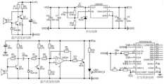
如图2所示,光线检测模块1包括稳压电路和光强度传感器;稳压电路采用稳压芯片XC6206,光强度传感器采用光强度数字转换芯片TSL2561,并配置必要的电容、电阻完成连接。TSL2561工作电压为2.7~3.5V,第一单片机工作电压为+5V,通过稳压芯片稳压芯片将VCC降为3.3V为其供电。TSL2561能够通过I2C总线访问,将TSL2561的I2C总线的4端口SCL、6端口SDA分别与第一单片机的P2.0、P2.1口对应连接,编程时需要模拟I2C总线的时序来访问TSL2561,5端口的INT引脚与第一单片机外部中断P3.2口相连,将光强度数字信号送到第一单片机中。As shown in Figure 2, the
如图3所示,人体检测模块2包括升压电路、超声波发射电路、超声波接收电路和信号转换电路。升压电路的1端口VIN与第一单片机的VCC相连,给LM2596提供5V工作电压,R13为8.2KΩ,R14为1.3KΩ,2端口VOUT输出电压为9V,为超声波发射电路提供工作电压。超声波发射电路在工作电压9V下产生40KHz的超声波。超声波接收电路不断接收发射来的超声波,在Vin端口不断产生一系列电压模拟信号。信号转换电路是以ADC0804为核心的AD转换电路,ADC0804的6端口与超声波接收电路的Vin端相连,11-18端口通过10KΩ的上拉电阻与单片机P0.0-P0.7相连,将超声波接收电路中的Vin模拟信号转换为数字信号并送到第一单片机中。As shown in FIG. 3 , the human
如图4所示,单片机控制模块3采用配置有第一单片机、电源电路、晶振电路以及复位电路的最小单片机系统,第一单片机采用STC89C52芯片。第一单片机根据光强度信号给出总控制,只有光照强度低于某个阈值时,灯光系统开始工作;通过判断两个超声波接收装置信号中断的时间以及先后顺序,判断进出人数并计算室内当前人数。例如,根据人数不同对室内三路灯光进行控制,P1.0-P2.2端口分别与灯光控制模块4中继电器的输入端相连。当人数大于50人时,3路灯光全亮;人数在20-50人之间时,亮两路灯;人数小于20人时,只亮一路灯;当人数为0时,三路灯光全灭。需要说明的是,灯光控制模块4启动方式与人数之间的关联可以根据需要进行灵活设置,在此不受限制。As shown in FIG. 4 , the single-chip
如图5所示,灯光控制模块4包括3个继电器,可对应控制3路灯光,且具有自动和手动两种模式。继电器输入端经第一开关分别与第一单片机的P1.0~P1.2接口相连,分别控制三路灯光。VCC、GND分别与第一单片机对应的VCC、GND相连,给模块供电。NC接口为常闭端口,NO接口为常开端口,COM接口为公共端口,通过第二开关选择COM端口与常闭端口NC或常开端口NO构成灯光回路。自动模式下,第一开关闭合同时第二开关向下闭合,灯光进入自动控制。手动模式下,第一开关断开,灯光由第二开关向上手动控制。在本实施例中,第二开关采用的是单刀双掷开关。As shown in FIG. 5 , the
如图1所示,此外,该系统还包括无线通信模块5和远程终端6;单片机控制模块3通过无线通信模块5与远程终端6连接;远程终端6,用于对单片机控制模块3输出的现有人数进行显示。As shown in Figure 1, in addition, the system also includes a
如图6所示,无线通信模块5采用型号为CC2530的射频模块,射频前端采用型号为C2591的射频前端芯片,CC2530的射频模块为基于ZigBee协议的无线射频终端。数据处理准确度高、效率高,保证了无线数据传输的精确度和实时性,配合CC2591射频前端,提高了其发射功率和接收灵敏度,能够达到准确的接收和发送数据。无线通信模块5适用于ZigBee无线传感网中协调器、路由器和终端设备三种设备任意一种。As shown in Figure 6, the
如图1所示,远程终端6配置有第二单片机、通信接口模块和显示屏;通信接口模块采用RS232通信接口;通信接口模块将第二单片机接收的现有人数传输至显示屏所在的上位机,并以显示屏进行展示。As shown in Figure 1, the
工作原理:首先监测室内的光线强度,再根据超声波传感器信号的中断次数及先后判断进出人数,并统计室内的现有人数;接着在光线强度超出预设阈值时生成系统启动信号,并在系统启动信号生成后根据现有人数的分布区间生成相应的控制信号;最后响应于控制信号后驱动对应数量的灯光回路启动。可根据进出教室的人的数量、教室内外的光线强度变化,对教室内的照明装置的开启实现智能化控制,在保证照明要求的前提下,降低了电力浪费。Working principle: firstly monitor the light intensity in the room, then judge the number of people entering and leaving the room according to the number of interruptions of the ultrasonic sensor signal and the sequence, and count the existing number of people in the room; then generate a system startup signal when the light intensity exceeds the preset threshold, and when the system starts After the signal is generated, a corresponding control signal is generated according to the distribution interval of the existing number of people; finally, a corresponding number of light circuits are driven to start in response to the control signal. According to the number of people entering and leaving the classroom and the change of light intensity inside and outside the classroom, intelligent control of the opening of the lighting devices in the classroom can be realized, and the power waste can be reduced on the premise of ensuring the lighting requirements.
以上所述的具体实施方式,对本实用新型的目的、技术方案和有益效果进行了进一步详细说明,所应理解的是,以上所述仅为本实用新型的具体实施方式而已,并不用于限定本实用新型的保护范围,凡在本实用新型的精神和原则之内,所做的任何修改、等同替换、改进等,均应包含在本实用新型的保护范围之内。The specific embodiments described above further describe the purpose, technical solutions and beneficial effects of the present invention in detail. It should be understood that the above are only specific embodiments of the present invention and are not intended to limit the present invention The protection scope of the utility model, any modification, equivalent replacement, improvement, etc. made within the spirit and principle of the present utility model shall be included within the protection scope of the present utility model.
Claims (10)
Priority Applications (1)
| Application Number | Priority Date | Filing Date | Title |
|---|---|---|---|
| CN202123428223.2UCN216600155U (en) | 2021-12-31 | 2021-12-31 | An intelligent classroom lighting control system based on ultrasonic sensor |
Applications Claiming Priority (1)
| Application Number | Priority Date | Filing Date | Title |
|---|---|---|---|
| CN202123428223.2UCN216600155U (en) | 2021-12-31 | 2021-12-31 | An intelligent classroom lighting control system based on ultrasonic sensor |
Publications (1)
| Publication Number | Publication Date |
|---|---|
| CN216600155Utrue CN216600155U (en) | 2022-05-24 |
Family
ID=81632333
Family Applications (1)
| Application Number | Title | Priority Date | Filing Date |
|---|---|---|---|
| CN202123428223.2UActiveCN216600155U (en) | 2021-12-31 | 2021-12-31 | An intelligent classroom lighting control system based on ultrasonic sensor |
Country Status (1)
| Country | Link |
|---|---|
| CN (1) | CN216600155U (en) |
- 2021
- 2021-12-31CNCN202123428223.2Upatent/CN216600155U/enactiveActive
Similar Documents
| Publication | Publication Date | Title |
|---|---|---|
| CN206004981U (en) | A kind of campus intelligent illuminating system based on Internet of Things | |
| CN201119069Y (en) | Intelligent control device for classroom lighting and air conditioning | |
| CN105263233A (en) | Intelligent lamplight control system based on WIFI and control method | |
| CN107015507B (en) | Comprehensive expansion system of central controller | |
| CN205491333U (en) | Classroom LED intelligence lighting system | |
| CN108901101A (en) | A kind of control method of cloud central control system | |
| CN202750271U (en) | Distributed intelligent lighting apparatus based on CAN-Ethernet architecture | |
| CN105005216A (en) | Intelligent classroom energy-saving control and state inquiry system | |
| CN204423123U (en) | Classroom illumination Based Intelligent Control and classroom occupied information delivery system | |
| CN202549151U (en) | Wireless monitoring and control practical training system of street lamp | |
| CN101938071B (en) | Energy-saving socket for printer and operating method thereof | |
| CN204044597U (en) | A kind of smart meeting room master control system circuit | |
| CN216600155U (en) | An intelligent classroom lighting control system based on ultrasonic sensor | |
| CN206608027U (en) | A kind of intelligent window control system based on Internet of Things | |
| CN210328095U (en) | Lighting energy-saving system | |
| CN209118126U (en) | A kind of smart classroom management platform based on mobile terminal | |
| CN206835433U (en) | A kind of classroom intelligent light control system | |
| CN216522258U (en) | Intelligent interactive air conditioner remote control | |
| CN205509153U (en) | Smart jack group control system based on thing networking | |
| CN204830335U (en) | Split -type air conditioner energy -saving control device based on it is wireless from network deployment | |
| CN115968086A (en) | An image recognition-based classroom energy-saving lighting control system and its control method | |
| CN209446993U (en) | A Smart Home Demonstration System | |
| CN209821690U (en) | Light intensity control device | |
| CN208300097U (en) | A kind of University Classroom's power saving apparatus | |
| CN220965227U (en) | Automatic control circuit of indoor distributed lighting equipment based on dual infrared sensor detection |
Legal Events
| Date | Code | Title | Description |
|---|---|---|---|
| GR01 | Patent grant | ||
| GR01 | Patent grant |