CN216495115U - Floor brush mechanism and cleaning device - Google Patents
Floor brush mechanism and cleaning deviceDownload PDFInfo
- Publication number
- CN216495115U CN216495115UCN202122747982.9UCN202122747982UCN216495115UCN 216495115 UCN216495115 UCN 216495115UCN 202122747982 UCN202122747982 UCN 202122747982UCN 216495115 UCN216495115 UCN 216495115U
- Authority
- CN
- China
- Prior art keywords
- water separator
- brush mechanism
- floor brush
- cover body
- cavity
- Prior art date
- Legal status (The legal status is an assumption and is not a legal conclusion. Google has not performed a legal analysis and makes no representation as to the accuracy of the status listed.)
- Ceased
Links
Images


Landscapes
- Cleaning In General (AREA)
Abstract
Description
Translated fromChinese技术领域technical field
本实用新型属于清洁技术领域,具体涉及一种地刷机构及清洁装置。The utility model belongs to the technical field of cleaning, in particular to a floor brush mechanism and a cleaning device.
背景技术Background technique
清洁设备,如洗地机,已逐渐地被应用在家庭地面清洁当中,其具有省力和清洁效果好等诸多优点。随着科学技术的快速发展,洗地机的形式也越来越多样,小巧而精致的洗地机受到了越来越多的家庭的欢迎。Cleaning equipment, such as washing machines, has been gradually used in household floor cleaning, which has many advantages such as labor saving and good cleaning effect. With the rapid development of science and technology, the forms of washing machines are becoming more and more diverse, and small and exquisite washing machines are welcomed by more and more families.
洗地机的地刷机构一般包括地刷壳体、设置在地刷壳体内腔中的分水器、及与壳体转动连接且位于分水器的出水口前侧的滚刷,分水器可将液体喷洒至滚刷上,以便滚刷对待清洁面进行清洁。然而,在长时间的使用后,分水器上会累积清洁时喷溅到其上的污物,导致分水器受到污染,经分水器喷出的液体也被污染,影响清洁效果。The floor brush mechanism of the washing machine generally includes a floor brush housing, a water separator arranged in the inner cavity of the floor brush housing, and a roller brush rotatably connected to the housing and located in front of the water outlet of the water separator. Liquid can be sprayed onto the roller brush to clean the surface to be cleaned. However, after a long period of use, the dirt sprayed on the water separator will accumulate on it during cleaning, which will cause the water separator to be polluted, and the liquid sprayed through the water separator will also be polluted, which will affect the cleaning effect.
然而现有技术中的分水器被收容在地刷壳体内。在需要对其进行清洁时,需要先拆卸壳体后再将分水器取出,操作繁杂,降低用户体验。However, the water separator in the prior art is accommodated in the floor brush housing. When it needs to be cleaned, it is necessary to disassemble the casing first and then take out the water separator, which is complicated to operate and reduces the user experience.
实用新型内容Utility model content
因此,本实用新型所要解决的技术问题是分水器与壳体拆卸复杂困难,而造成清洁困难。Therefore, the technical problem to be solved by the present invention is that the disassembly of the water separator and the casing is complicated and difficult, resulting in difficulty in cleaning.
为解决上述技术问题,本实用新型提供一种地刷机构,包括:In order to solve the above-mentioned technical problems, the utility model provides a ground brush mechanism, comprising:
壳体,具有收容腔、及与所述收容腔连通的取放口;a housing, having a receiving cavity and a pick-and-place port communicating with the receiving cavity;
盖体,可拆卸地设在所述取放口上;a cover body, which is detachably arranged on the pick-and-place port;
分水器,与所述盖体连接;所述分水器可随所述盖体,经所述取放口安装在所述收容腔内或从所述收容腔内取出。The water divider is connected with the cover body; the water divider can be installed in the receiving cavity with the cover body through the pick-and-place port or taken out from the receiving cavity.
可选地,上述的地刷机构,所述取放口分布在所述壳体的顶部,所述分水器随所述盖体经所述取放口做升降运动。Optionally, in the above-mentioned floor brush mechanism, the pick-and-place ports are distributed on the top of the housing, and the water separator moves up and down with the cover body through the pick-and-place ports.
可选地,上述的地刷机构,所述分水器的底部上设置有进液通道,所述进液通道与所述分水器内的分水腔通过至少一个连通口连通;Optionally, in the above-mentioned floor brush mechanism, a liquid inlet channel is provided on the bottom of the water separator, and the liquid inlet channel is communicated with the water separation cavity in the water separator through at least one communication port;
所述地刷机构还包括与供给箱连接且至少部分设置在所述收容腔内的输送件,所述分水器的底部沿竖向套接在所述输送件的外壁外,以使得所述进液通道与所述输送件的内腔密封连通。The floor brush mechanism further includes a conveying member connected to the supply box and at least partially disposed in the receiving cavity, and the bottom of the water separator is vertically sleeved outside the outer wall of the conveying member, so that the The liquid inlet channel is in sealing communication with the inner cavity of the conveying member.
可选地,上述的地刷机构,所述地刷机构还包括套设在所述输送件的外壁上的密封件,所述进液通道可滑动地密封套设在所述密封件的外壁上。Optionally, in the above-mentioned floor brush mechanism, the floor brush mechanism further includes a sealing member sleeved on the outer wall of the conveying member, and the liquid inlet channel is slidably sleeved on the outer wall of the sealing member. .
可选地,上述的地刷机构,至少一个所述连通口分布在所述进液通道的侧壁上,以使至少一个所述连通口侧向连通所述进液通道和所述分水器的分水腔。Optionally, in the above-mentioned floor brush mechanism, at least one of the communication ports is distributed on the side wall of the liquid inlet channel, so that at least one of the communication ports laterally communicates with the liquid inlet channel and the water separator. the water divider.
可选地,上述的地刷机构,所述进液通道的内壁上还设置有过滤件,所述过滤件位于所述连通口和所述输送件之间。Optionally, in the above-mentioned floor brush mechanism, a filter element is further provided on the inner wall of the liquid inlet channel, and the filter element is located between the communication port and the conveying element.
可选地,上述的地刷机构,所述分水器和所述盖体的其中之一上设置有对接孔,所述分水器和所述盖体的另一个上设置有与所述对接孔插接的对接柱;Optionally, in the above-mentioned floor brush mechanism, one of the water divider and the cover body is provided with a docking hole, and the other one of the water divider and the cover body is provided with a docking hole. Docking post for hole insertion;
所述地刷机构还包括紧固件,所述紧固件与所述对接柱螺纹连接且与所述对接孔抵可选地,上述的地刷机构,所述壳体和所述盖体通过锁定组件连接。The floor brush mechanism further includes a fastener, which is threadedly connected to the butt column and abuts against the butt hole. Optionally, in the above-mentioned floor brush mechanism, the casing and the cover pass through Lock assembly connection.
可选地,上述的地刷机构,所述盖体包括上盖及与所述上盖连接且形成容置腔的下盖;Optionally, in the above-mentioned floor brush mechanism, the cover body includes an upper cover and a lower cover connected with the upper cover and forming an accommodating cavity;
所述锁定组件包括部分设置在所述容置腔内的按压件、及与所述按压件连接的卡持件,所述按压件的剩余部分通过所述上盖的通孔伸出至所述容置腔外,所述卡持件的一端自所述下盖上的让位孔伸出至所述容置腔外,以与所述壳体卡接配合;The locking assembly includes a pressing member partially disposed in the accommodating cavity, and a clamping member connected with the pressing member, and the remaining part of the pressing member protrudes through the through hole of the upper cover to the Outside the accommodating cavity, one end of the holding member protrudes out of the accommodating cavity from the accommodating hole on the lower cover, so as to be snap-fitted with the casing;
所述锁定组件还包括设置在所述容置腔内的弹性件,所述按压件受所述弹性件的偏压力趋于使所述卡持件与所述壳体卡接。The locking assembly further includes an elastic member disposed in the accommodating cavity, and the pressing member tends to be engaged with the housing by the biasing force of the elastic member.
本实用新型还提供一种清洁装置,包括如上所述的地刷机构。The utility model also provides a cleaning device, which includes the above-mentioned floor brush mechanism.
可选地,上述的清洁装置,所述清洁装置还包括通过水路输送机构与所述分水器连通的供给箱。Optionally, in the above-mentioned cleaning device, the cleaning device further includes a supply tank that communicates with the water separator through a water channel conveying mechanism.
本实用新型提供的技术方案,具有以下优点:通过将盖体与壳体可拆卸连接,将分水器与盖体连接,以使得盖体与壳体安装或拆卸时,分水器经设置在壳体上的取放口安装于壳体的收容腔内或自壳体的收容腔内取出,方便用户对分水器进行清洁,保证清洁效率,且提高用户使用体验。The technical solution provided by the utility model has the following advantages: by detachably connecting the cover body and the casing, the water separator is connected with the cover body, so that when the cover body and the casing are installed or disassembled, the water separator is arranged on the The pick-and-place port on the housing is installed in or taken out from the housing cavity of the housing, which facilitates the user to clean the water separator, ensures the cleaning efficiency, and improves the user experience.
附图说明Description of drawings
为了更清楚地说明本实用新型具体实施方式或现有技术中的技术方案,下面将对具体实施方式或现有技术描述中所需要使用的附图作简单地介绍,显而易见,下面描述中的附图是本实用新型的一些实施方式,对于本领域普通技术人员来讲,在不付出创造性劳动的前提下,还可以根据这些附图获得其他的附图。In order to more clearly illustrate the specific embodiments of the present invention or the technical solutions in the prior art, the following briefly introduces the accompanying drawings that need to be used in the description of the specific embodiments or the prior art. Obviously, the accompanying drawings in the following description The drawings are some embodiments of the present invention. For those of ordinary skill in the art, other drawings can also be obtained from these drawings without creative work.
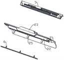
图1为本实用新型实施例1提供的地刷机构的结构示意图;1 is a schematic structural diagram of a floor brush mechanism provided in Embodiment 1 of the present invention;
图2为本实用新型实施例1提供的地刷机构的另一结构示意图;2 is another schematic structural diagram of the floor brush mechanism provided in Embodiment 1 of the present utility model;
图3为本实施新型实施例1提供的盖体、锁定组件之间的连接关系图;3 is a diagram of the connection relationship between the cover body and the locking assembly provided by the first embodiment of the present invention;
图4为本实施新型实施例1提供的盖体、分水器之间的连接关系图;FIG. 4 is a diagram of the connection relationship between the cover body and the water separator provided by Embodiment 1 of the present embodiment;
图5为本实施新型实施例1提供的盖体、锁定组件之间的连接关系爆炸示意图;5 is an exploded schematic diagram of the connection relationship between the cover body and the locking assembly provided by the first embodiment of the present invention;
图6为本实施新型实施例1提供的地刷机构的剖面示意图;6 is a schematic cross-sectional view of the floor brush mechanism provided in Embodiment 1 of the present embodiment;
图7为图6中的部分示意图。FIG. 7 is a partial schematic diagram of FIG. 6 .
附图标记说明:Description of reference numbers:
100-地刷机构;100-ground brush mechanism;
1-壳体;11-取放口;12-收容腔;1- shell; 11- pick and place port; 12- containment cavity;
2-盖体;21-上盖;211-通孔;22-下盖;221-让位孔;23-装饰盖;24-固定件;25-对接柱;26-容置腔;2-cover body; 21-upper cover; 211-through hole; 22-lower cover; 221-give-way hole; 23-decorative cover; 24-fixing part; 25-docking column; 26-accommodating cavity;
3-清洁组件;3- Clean the components;
4-锁定组件;41-按压件;411-按压部;42-卡持件;421-卡持部;422-槽口;43-弹性件;4-locking assembly; 41-pressing piece; 411-pressing part; 42-holding piece; 421-holding part; 422-notch; 43-elastic piece;
5-分水器;51-对接孔;52-进液通道;53-连通口;54-喷水口;55-安装柱;5- water separator; 51- docking hole; 52- liquid inlet channel; 53- communication port; 54- water spray port; 55- installation column;
6-紧固件;6- Fasteners;
7-输送件;71-台阶;7-conveyor; 71-step;
8-密封件;8-seals;
9-过滤件。9- Filter element.
具体实施方式Detailed ways
下面将结合附图对本实用新型的技术方案进行清楚、完整地描述,显然,所描述的实施例是本实用新型一部分实施例,而不是全部的实施例。下文中将参考附图并结合实施例来详细说明本实用新型。需要说明的是,在不冲突的情况下,本实用新型中的实施例及实施例中的特征可以相互组合。The technical solutions of the present invention will be clearly and completely described below with reference to the accompanying drawings. Obviously, the described embodiments are a part of the embodiments of the present invention, not all of the embodiments. Hereinafter, the present invention will be described in detail with reference to the accompanying drawings and in conjunction with the embodiments. It should be noted that the embodiments of the present invention and the features of the embodiments may be combined with each other under the condition of no conflict.
需要说明的是,本实用新型的说明书和权利要求书及上述附图中的术语“第一”、“第二”等是用于区别类似的对象,而不必用于描述特定的顺序或先后次序。It should be noted that the terms "first" and "second" in the description and claims of the present invention and the above drawings are used to distinguish similar objects, and are not necessarily used to describe a specific sequence or sequence. .
在本实用新型中,在未作相反说明的情况下,使用的方位词如“上、下、顶、底”通常是针对附图所示的方向而言的,或者是针对部件本身在竖直、垂直或重力方向上而言的;同样地,为便于理解和描述,“内、外”是指相对于各部件本身的轮廓的内、外,但上述方位词并不用于限制本实用新型。In the present utility model, unless otherwise stated, the directional words used such as "upper, lower, top, bottom" are usually for the directions shown in the drawings, or for the components themselves in the vertical direction. , vertical or gravitational direction; similarly, for ease of understanding and description, "inside and outside" refers to the inside and outside of the contour of each component itself, but the above-mentioned orientation words are not used to limit the present invention.
实施例1Example 1
请结合图1,本实施例提供一种地刷机构100,用于对待清洁面进行清洁。其中,待清洁面可以为地面、墙面,也可以为待清洁物体的表面,本实施例不对待清洁面做具体限定,根据实际情况而定。Please refer to FIG. 1 , this embodiment provides a
具体的,地刷机构100包括壳体1、盖体2、清洁组件3及驱动件。盖体2与壳体1连接且形成收容空间,清洁组件3转动设置在该收容空间内,驱动件驱动清洁组件3转动以对待清洁面进行清洁。在本实施例中,该驱动件为电机,电机通过传动件与清洁组件3连接。传动件将电机的旋转驱动力传递至清洁组件3,以驱使清洁组件3转动。传动件为皮带传动等常规结构,在此不做赘述。Specifically, the
清洁组件3包括支撑件及与支撑件连接的清洁件,清洁件与支撑件可以为固定连接,也可以为可拆卸连接。为了节省清洁成本,清洁件与支撑件可拆卸连接,以使得支撑件和清洁件中任一个损坏时,仅需更换损坏的支撑件或清洁件,无需将清洁组件3整体进行更换。在本实施例中,清洁组件3为滚刷。The cleaning assembly 3 includes a support member and a cleaning member connected to the support member. The cleaning member and the support member may be fixedly connected or detachably connected. In order to save the cleaning cost, the cleaning member is detachably connected to the supporting member, so that when any one of the supporting member and the cleaning member is damaged, only the damaged supporting member or the cleaning member needs to be replaced, and the entire cleaning assembly 3 does not need to be replaced. In this embodiment, the cleaning assembly 3 is a roller brush.
由于清洁组件3与壳体1转动连接,清洁组件3在工作时转动产生离心力,少许污物在离心力的作用下被甩至盖体2上,避免污物直接溅射到用户身上,提高用户体验。因此,在本实施例中,盖体2与壳体1之间可拆卸连接。将盖体2与壳体1设置成可拆卸连接的目的在于:在需要方便对清洁组件3进行拆装的同时,方便对盖体2的内表面(朝向清洁组件3设置的一面)进行清洁。Because the cleaning component 3 is connected with the housing 1 in rotation, the cleaning component 3 rotates during operation to generate centrifugal force, and a little dirt is thrown onto the cover 2 under the action of centrifugal force, preventing the dirt from being directly splashed on the user and improving the user experience. . Therefore, in this embodiment, the cover body 2 and the casing 1 are detachably connected. The purpose of detachably connecting the cover body 2 and the housing 1 is to facilitate cleaning of the inner surface of the cover body 2 (the side facing the cleaning component 3 ) when the cleaning assembly 3 needs to be easily disassembled and assembled.
请结合图2至图5,在本实施例中,壳体1和盖体2通过锁定组件4连接,以实现壳体1和盖体2的可拆卸连接。其中,盖体2包括上盖21及与上盖21连接且形成容置腔26的下盖22。于地刷机构100的高度方向上(箭头a指示方向),上盖21和下盖22呈上下分布。Please refer to FIG. 2 to FIG. 5 , in this embodiment, the housing 1 and the cover 2 are connected by a locking assembly 4 , so as to realize the detachable connection between the housing 1 and the cover 2 . The cover body 2 includes an
上盖21和下盖22之间也为可拆卸连接。在本实施例中,上盖21和下盖22卡合连接。具体的,上盖21和下盖22的其中之一上设置有卡槽,上盖21和下盖22的另一个上设置有与卡槽卡合的卡柱,卡柱与卡槽卡合以使得上盖21与下盖22安装连接。在其他实施例中,上盖21和下盖22之间也可通过螺栓等进行连接,在此不做具体限定,根据实际情况而定。The
锁定组件4包括部分设置在容置腔26内的按压件41、及与按压件41连接的卡持件42,按压件41的剩余部分作为按压部411,以便于用户施加外力与按压部411上,进而驱动按压件41移动以带动卡持件42移动。为了方便用户施力,故按压件41的剩余部分伸出至容置腔26外。相应的,上盖21上设置有与容置腔26连通的通孔211,该通孔211供按压件41的剩余部分伸出至容置腔26外。The locking assembly 4 includes a pressing
卡持件42用于与壳体1卡持,进而使得盖体2与壳体1之间连接。相应的,下盖22上设置有让位孔221,卡持件42的一端自下盖22上的让位孔221伸出至容置腔26外,以与壳体1卡接配合。其中,卡持件42与壳体1卡接配合的部分为卡持部421。壳体1上设置有与卡持部421卡接配合的容置槽,卡持部421被收容在该容置槽内时,盖体2与壳体1卡接配合以实现连接。The holding
在本实施例中,按压件41与卡持件42一体成型设置,以简化生产制造工艺。在其他实施例中,按压件41和卡持件42也可分别成型,再通过粘接、卡接等连接方式实现固定连接,在此不做具体限定,根据实际情况而定。In this embodiment, the pressing
锁定组件4还包括设置在容置腔26内的弹性件43,按压件41受弹性件43的偏压力趋于使卡持件42与壳体1卡接。在本实施例中,该弹性件43为弹簧。弹簧具有初始状态和压缩状态,位于初始状态时,弹簧的弹性力使得卡持件42的卡持部421与壳体1的容置槽卡接配合。施加外力于按压部411以驱动按压件41移动继而带动卡持件42与容置槽脱离,壳体1与盖体2分离,继而使得弹性件43处于压缩状态。The locking assembly 4 further includes an
在本实施例中,盖体2还包括与下盖22连接且设置在容置腔26内的固定件24,卡持件42上设置有槽口422。卡持件42通过该槽口422套设在固定件24上,弹性件43设置在该槽口422内。In this embodiment, the cover body 2 further includes a fixing
弹性件43的一端与卡持件42固定连接,弹性件43的另一端与固定件24固定连接。并且,固定件24上还设置有导向柱,弹性件43的一端套设在该导向柱上,以导向弹性件43压缩时的方向。One end of the
盖体2还包括与上盖21连接的装饰盖23,该装饰盖23设置在上盖21的通孔211处,以使得按压部411暴露的同时,将通孔211的剩余部分隐藏,以提高盖体2及整个地刷机构100的美观性。The cover body 2 also includes a
请结合图6及图7,为了提高地刷机构100的清洁效率,地刷机构100还包括分水器5。以清洁组件3所在位置为壳体1的前方,分水器5设置在清洁组件3的后方。且该分水器5用于向清洁组件3喷水以使得清洁组件3湿润,从而使得待清洁面上的污渍能够附着在湿润的清洁组件3上。因此,分水器5喷水口54朝向清洁组件3。Please refer to FIG. 6 and FIG. 7 , in order to improve the cleaning efficiency of the
但是,分水器5在长期使用后,分水器5上会累积清洁组件3在进行清洁工作时喷溅至其上的污物,从而导致分水器5受到污染,进而使得经分水器5喷出的液体也会受到污染,影响清洁效果。However, after the
现有技术中,分水器5一般直接内置于壳体1内。在需要对分水器5进行清洁时,需要先将壳体1进行拆卸,然后才能将分水器5取出进行清洁。整个拆卸过程较为复杂,并且清理完之后还需要再将壳体1进行安装,降低用户体验。In the prior art, the
为了解决上述的分水器5与壳体1拆卸或安装复杂的问题,本实施例中将盖体2与分水器5直接连接,并且使得分水器5能随盖体2的移动而移动。如,盖体2与壳体1拆卸时,盖体2能够同时带动分水器5与壳体1分离,进而对其进行清洁。同样的,当将盖体2与壳体1安装时,分水器5同时能够随盖体2的安装动作安装于壳体1内,更加方便快捷。In order to solve the above-mentioned problem of complicated disassembly or installation of the
具体的,壳体1具有收容腔12及与收容腔12连通的取放口11,盖体2可拆卸地设置在取放口11上。而分水器5与盖体2连接,当盖体2安装于取放口11上或自取放口11拆卸时,分水器5可随盖体2经取放口11安装在收容腔12内或从收容腔12内取出。Specifically, the housing 1 has an
为了在取放分水器5的时候不对其他器件的运行造成影响或干涉,在本实施例中,于地刷机构100的高度方向上(箭头a指示方向),取放口11分布在壳体1的顶部,分水器5随盖体2经取放口11做升降运动。即,分水器5沿地刷机构100的高度方向运动,且当分水器5安装在收容腔12内时,盖体2安装于取放口11处。In order not to affect or interfere with the operation of other devices when taking and placing the
分水器5与盖体2之间固定连接。在本实施例中,分水器5和盖体2的其中之一上设置有对接孔51,分水器5和盖体2的另一个上设置有与对接孔51插接的对接柱25,对接柱25与对接孔51插接卡合以实现分水器5和盖体2的固定连接。The
为了确保分水器5和盖体2之间连接的稳固程度,地刷机构100还包括紧固件6,紧固件6与对接柱25螺纹连接且与对接孔51抵持。在本实施例中,对接柱25设置在盖体2上,对接孔51设置在分水器5上。当需要将盖体2与分水器5进行安装时,使得对接柱25穿过对接孔51,然后将紧固件6自对接柱25远离盖体2的一端与对接柱25螺纹连接,直至紧固件6远离盖体2的端部与对接孔51抵持,从而使得盖体2与分水器5固定连接。In order to ensure the firmness of the connection between the
同理,在需要将分水器5与盖体2拆卸时,将紧固件6反向旋转以使得紧固件6远离盖体2的端部与对接孔51脱离抵持,直至紧固件6与对接柱25完全脱离后,使得对接柱25与对接孔51分离,进而使得盖体2与分水器5分离。Similarly, when the
呈上述,分水器5的喷水口54向清洁组件3喷射液体。因而,地刷机构100还包括与供给箱连接且至少部分设置在收容腔12内的输送件7,分水器5与输送件7连通,以使得输送件7将供给箱内的液体输送至分水器5并自分水器5的喷水口54喷向至清洁组件3。As described above, the
分水器5的底部上设置有进液通道52。呈上述,分水器5随盖体2,经取放口11做升降运动,故,在本实施例中,分水器5安装于收容腔12内时,分水器5的底部沿竖向套接在输送件7的外壁外,以使得进液通道52与输送件7的内腔密封连通。A
为了保证输送件7和进液通道52连接处的密封性,以减小液体自输送件7和进液通道52连接处泄漏的可能性,地刷机构100还包括套设在输送件7的外壁上的密封件8。当进液通道52安装于收容腔12内时,进液通道52可滑动地密封套设在密封件8的外壁上。在本实施例中,该密封件8可以为密封圈或密封套等,只需达到密封效果即可,在此不做具体限定,根据实际情况而定。In order to ensure the tightness of the connection between the conveying member 7 and the
在本实施例中,输送件7上还形成有台阶71,该台阶71用于支撑密封件8,防止密封件8在分水器5与输送件7对接安装的过程中,在外力作用下移位。其中,输送件7的外壁向内凹陷形成有安装槽,该安装槽作为台阶71,以使得密封件8套设在该安装槽内时,密封件8的两端皆与安装槽抵持,进而防止密封件8移位。In this embodiment, a
进液通道52与分水器5内的分水腔通过至少一个连通口53连通,喷水口54与分水腔连通。在本实施例中,连通口53设置有一个,该连通口53设置在分水器5内靠近清洁组件3的位置。在其他实施例中,连通口53的个数也可为其他,例如两个、三个等,在此不做具体限定,根据实际情况而定。The
至少一个连通口53分布在进液通道52的侧壁上,以使至少一个连通口53侧向连通进液通道52和分水器5的分水腔。这样设置的目的在于:减小将连通口53竖向排布时,液体施加给输送件7与进液通道52连接处的压力,减小液体自输送件7与进液通道52连接处泄漏的可能性。并且,防止在将分水器5从收容腔12内拆卸时,分水腔内残留的水经竖直设置的连通孔211流至收容腔12内,或是滴落在待清洁表面上。At least one
同时,为了保证分水器5的喷水效率及清洁组件3的清洁效率,进液通道52的内壁上还设置有过滤件9,过滤件9位于连通口53和输送件7之间。过滤件9可将自输送件7内腔输出的液体预先过滤,以使得进入至分水腔内的液体相对洁净,从而防止液体中存留颗粒物,使得颗粒物进入至分水腔内堵塞喷水口54。At the same time, in order to ensure the water spraying efficiency of the
具体的,分水器5上设置有安装柱55,安装柱55位于进液通道52内,过滤件9可拆卸地设置在该安装柱55上。在本实施例中,该过滤件9上设置有安装孔,过滤件9通过该安装孔套设在安装柱55上。该过滤件9可以为过滤海绵或者过滤网等,在此不做具体限定,只需达到过滤效果即可。Specifically, the
综上所述:通过将盖体2与壳体1可拆卸连接,将分水器5与盖体2连接,以使得盖体2与壳体1安装或拆卸时,分水器5经设置在壳体1上的取放口11安装于壳体1的收容腔12内或自壳体1的收容腔12内取出,方便用户对分水器5进行清洁,保证清洁效率,且提高用户使用体验。To sum up: by detachably connecting the cover body 2 and the shell body 1, the
实施例2Example 2
本实施例提供一种清洁装置,包括杆体、与杆体连接的主机及与主机对接安装的地刷机构100,其中,地刷机构100为上述实施例1中的地刷机构100。地刷机构100上的输送件7与供给箱连接,以将供给箱内的液体通过分水器5输送至清洁组件3。This embodiment provides a cleaning device including a rod body, a host connected to the rod body, and a
为了方便液体的输送以保证清洁效率,清洁装置还包括通过水路输送机构与分水器5连通的供给箱。在本实施例中,供给箱设置在杆体上,水路输送机构包括泵体及连通输送件7和泵体的输送管,从而使得清洁装置整体更为紧凑。在其他实施例中,供给箱也可单独设置,在此不做具体限定,根据实际情况而定。In order to facilitate the transportation of the liquid to ensure the cleaning efficiency, the cleaning device further includes a supply tank which is communicated with the
显然,上述所描述的实施例仅仅是本实用新型一部分的实施例,而不是全部的实施例。基于本实用新型中的实施例,本领域普通技术人员在没有做出创造性劳动前提下,可以做出其它不同形式的变化或变动,都应当属于本实用新型保护的范围。Obviously, the above-described embodiments are only a part of the embodiments of the present invention, but not all of the embodiments. Based on the embodiments of the present invention, those of ordinary skill in the art can make other changes or changes in different forms without creative work, which should all belong to the protection scope of the present invention.
Claims (11)
Translated fromChinesePriority Applications (1)
| Application Number | Priority Date | Filing Date | Title |
|---|---|---|---|
| CN202122747982.9UCN216495115U (en) | 2021-11-10 | 2021-11-10 | Floor brush mechanism and cleaning device |
Applications Claiming Priority (1)
| Application Number | Priority Date | Filing Date | Title |
|---|---|---|---|
| CN202122747982.9UCN216495115U (en) | 2021-11-10 | 2021-11-10 | Floor brush mechanism and cleaning device |
Publications (1)
| Publication Number | Publication Date |
|---|---|
| CN216495115Utrue CN216495115U (en) | 2022-05-13 |
Family
ID=81528298
Family Applications (1)
| Application Number | Title | Priority Date | Filing Date |
|---|---|---|---|
| CN202122747982.9UCeasedCN216495115U (en) | 2021-11-10 | 2021-11-10 | Floor brush mechanism and cleaning device |
Country Status (1)
| Country | Link |
|---|---|
| CN (1) | CN216495115U (en) |
Cited By (1)
| Publication number | Priority date | Publication date | Assignee | Title |
|---|---|---|---|---|
| EP4581997A1 (en)* | 2024-01-08 | 2025-07-09 | Zhejiang Shaoxing Supor Domestic Electrical Appliance Co., Ltd | Floor brush assembly and cleaning device |
- 2021
- 2021-11-10CNCN202122747982.9Upatent/CN216495115U/ennot_activeCeased
Cited By (1)
| Publication number | Priority date | Publication date | Assignee | Title |
|---|---|---|---|---|
| EP4581997A1 (en)* | 2024-01-08 | 2025-07-09 | Zhejiang Shaoxing Supor Domestic Electrical Appliance Co., Ltd | Floor brush assembly and cleaning device |
Similar Documents
| Publication | Publication Date | Title |
|---|---|---|
| CN219070149U (en) | Water tanks, filters, adapters, base stations and cleaning systems | |
| CN113876263A (en) | Cleaning device and cleaning system | |
| WO2018149311A1 (en) | Robotic cleaner | |
| CN216495115U (en) | Floor brush mechanism and cleaning device | |
| WO2021103691A1 (en) | Water squeezing type roller cleaning device | |
| CN116407022A (en) | Cleaning apparatus | |
| KR20240009500A (en) | cleaning device | |
| CN219962770U (en) | Cleaning base of a floor washing machine and a floor washing machine | |
| CN220824226U (en) | A floor cleaning device | |
| CN218528619U (en) | Cleaning robot | |
| CN217408721U (en) | Cleaning mechanism and cleaning device | |
| CN115736727A (en) | Multifunctional surface cleaning system with multiple cleaning components | |
| WO2023124845A1 (en) | Cleaning device | |
| CN212972876U (en) | Water pump mounting structure of mop cleaning barrel | |
| CN112998596A (en) | Cleaning device | |
| CN112998575A (en) | Informationized building construction is with portable cooling dust device | |
| CN222885347U (en) | Base station | |
| CN223262854U (en) | cleaning equipment | |
| CN218280788U (en) | A filtration system for cleaning machine basic station | |
| CN217628902U (en) | Brush head assembly of cleaning equipment and cleaning equipment | |
| CN217185994U (en) | Cleaning device with sewage tank | |
| CN217852725U (en) | Dust cup assembly, portable hand-held cleaning equipment and cleaning equipment | |
| CN223220401U (en) | Dirt collection tanks and cleaning equipment | |
| CN218870153U (en) | Cloth art cleaner | |
| CN219126238U (en) | Surface cleaning device with easy-to-clean dirt inlet pipe |
Legal Events
| Date | Code | Title | Description |
|---|---|---|---|
| GR01 | Patent grant | ||
| GR01 | Patent grant | ||
| IW01 | Full invalidation of patent right | Decision date of declaring invalidation:20231226 Decision number of declaring invalidation:564060 Granted publication date:20220513 | |
| IW01 | Full invalidation of patent right |