CN216455493U - prosthetic heart valve - Google Patents
prosthetic heart valveDownload PDFInfo
- Publication number
- CN216455493U CN216455493UCN202121033967.1UCN202121033967UCN216455493UCN 216455493 UCN216455493 UCN 216455493UCN 202121033967 UCN202121033967 UCN 202121033967UCN 216455493 UCN216455493 UCN 216455493U
- Authority
- CN
- China
- Prior art keywords
- commissure
- attachment member
- tab
- frame
- prosthetic heart
- Prior art date
- Legal status (The legal status is an assumption and is not a legal conclusion. Google has not performed a legal analysis and makes no representation as to the accuracy of the status listed.)
- Active
Links
Images


Classifications
- A—HUMAN NECESSITIES
- A61—MEDICAL OR VETERINARY SCIENCE; HYGIENE
- A61F—FILTERS IMPLANTABLE INTO BLOOD VESSELS; PROSTHESES; DEVICES PROVIDING PATENCY TO, OR PREVENTING COLLAPSING OF, TUBULAR STRUCTURES OF THE BODY, e.g. STENTS; ORTHOPAEDIC, NURSING OR CONTRACEPTIVE DEVICES; FOMENTATION; TREATMENT OR PROTECTION OF EYES OR EARS; BANDAGES, DRESSINGS OR ABSORBENT PADS; FIRST-AID KITS
- A61F2/00—Filters implantable into blood vessels; Prostheses, i.e. artificial substitutes or replacements for parts of the body; Appliances for connecting them with the body; Devices providing patency to, or preventing collapsing of, tubular structures of the body, e.g. stents
- A61F2/02—Prostheses implantable into the body
- A61F2/24—Heart valves ; Vascular valves, e.g. venous valves; Heart implants, e.g. passive devices for improving the function of the native valve or the heart muscle; Transmyocardial revascularisation [TMR] devices; Valves implantable in the body
- A61F2/2412—Heart valves ; Vascular valves, e.g. venous valves; Heart implants, e.g. passive devices for improving the function of the native valve or the heart muscle; Transmyocardial revascularisation [TMR] devices; Valves implantable in the body with soft flexible valve members, e.g. tissue valves shaped like natural valves
- A61F2/2418—Scaffolds therefor, e.g. support stents
- A—HUMAN NECESSITIES
- A61—MEDICAL OR VETERINARY SCIENCE; HYGIENE
- A61F—FILTERS IMPLANTABLE INTO BLOOD VESSELS; PROSTHESES; DEVICES PROVIDING PATENCY TO, OR PREVENTING COLLAPSING OF, TUBULAR STRUCTURES OF THE BODY, e.g. STENTS; ORTHOPAEDIC, NURSING OR CONTRACEPTIVE DEVICES; FOMENTATION; TREATMENT OR PROTECTION OF EYES OR EARS; BANDAGES, DRESSINGS OR ABSORBENT PADS; FIRST-AID KITS
- A61F2/00—Filters implantable into blood vessels; Prostheses, i.e. artificial substitutes or replacements for parts of the body; Appliances for connecting them with the body; Devices providing patency to, or preventing collapsing of, tubular structures of the body, e.g. stents
- A61F2/02—Prostheses implantable into the body
- A61F2/24—Heart valves ; Vascular valves, e.g. venous valves; Heart implants, e.g. passive devices for improving the function of the native valve or the heart muscle; Transmyocardial revascularisation [TMR] devices; Valves implantable in the body
- A61F2/2412—Heart valves ; Vascular valves, e.g. venous valves; Heart implants, e.g. passive devices for improving the function of the native valve or the heart muscle; Transmyocardial revascularisation [TMR] devices; Valves implantable in the body with soft flexible valve members, e.g. tissue valves shaped like natural valves
- A61F2/2415—Manufacturing methods
- A—HUMAN NECESSITIES
- A61—MEDICAL OR VETERINARY SCIENCE; HYGIENE
- A61F—FILTERS IMPLANTABLE INTO BLOOD VESSELS; PROSTHESES; DEVICES PROVIDING PATENCY TO, OR PREVENTING COLLAPSING OF, TUBULAR STRUCTURES OF THE BODY, e.g. STENTS; ORTHOPAEDIC, NURSING OR CONTRACEPTIVE DEVICES; FOMENTATION; TREATMENT OR PROTECTION OF EYES OR EARS; BANDAGES, DRESSINGS OR ABSORBENT PADS; FIRST-AID KITS
- A61F2220/00—Fixations or connections for prostheses classified in groups A61F2/00 - A61F2/26 or A61F2/82 or A61F9/00 or A61F11/00 or subgroups thereof
- A61F2220/0025—Connections or couplings between prosthetic parts, e.g. between modular parts; Connecting elements
- A61F2220/0075—Connections or couplings between prosthetic parts, e.g. between modular parts; Connecting elements sutured, ligatured or stitched, retained or tied with a rope, string, thread, wire or cable
- A—HUMAN NECESSITIES
- A61—MEDICAL OR VETERINARY SCIENCE; HYGIENE
- A61F—FILTERS IMPLANTABLE INTO BLOOD VESSELS; PROSTHESES; DEVICES PROVIDING PATENCY TO, OR PREVENTING COLLAPSING OF, TUBULAR STRUCTURES OF THE BODY, e.g. STENTS; ORTHOPAEDIC, NURSING OR CONTRACEPTIVE DEVICES; FOMENTATION; TREATMENT OR PROTECTION OF EYES OR EARS; BANDAGES, DRESSINGS OR ABSORBENT PADS; FIRST-AID KITS
- A61F2220/00—Fixations or connections for prostheses classified in groups A61F2/00 - A61F2/26 or A61F2/82 or A61F9/00 or A61F11/00 or subgroups thereof
- A61F2220/0025—Connections or couplings between prosthetic parts, e.g. between modular parts; Connecting elements
- A61F2220/0091—Connections or couplings between prosthetic parts, e.g. between modular parts; Connecting elements connected by a hinged linkage mechanism, e.g. of the single-bar or multi-bar linkage type
- A—HUMAN NECESSITIES
- A61—MEDICAL OR VETERINARY SCIENCE; HYGIENE
- A61F—FILTERS IMPLANTABLE INTO BLOOD VESSELS; PROSTHESES; DEVICES PROVIDING PATENCY TO, OR PREVENTING COLLAPSING OF, TUBULAR STRUCTURES OF THE BODY, e.g. STENTS; ORTHOPAEDIC, NURSING OR CONTRACEPTIVE DEVICES; FOMENTATION; TREATMENT OR PROTECTION OF EYES OR EARS; BANDAGES, DRESSINGS OR ABSORBENT PADS; FIRST-AID KITS
- A61F2230/00—Geometry of prostheses classified in groups A61F2/00 - A61F2/26 or A61F2/82 or A61F9/00 or A61F11/00 or subgroups thereof
- A61F2230/0002—Two-dimensional shapes, e.g. cross-sections
- A61F2230/0028—Shapes in the form of latin or greek characters
- A61F2230/0054—V-shaped
Landscapes
- Health & Medical Sciences (AREA)
- Engineering & Computer Science (AREA)
- Cardiology (AREA)
- Biomedical Technology (AREA)
- Heart & Thoracic Surgery (AREA)
- Transplantation (AREA)
- Oral & Maxillofacial Surgery (AREA)
- Vascular Medicine (AREA)
- Life Sciences & Earth Sciences (AREA)
- Animal Behavior & Ethology (AREA)
- General Health & Medical Sciences (AREA)
- Public Health (AREA)
- Veterinary Medicine (AREA)
- Manufacturing & Machinery (AREA)
- Prostheses (AREA)
Abstract
Translated fromChinese
Description
Translated fromChinese相关申请的交叉引用CROSS-REFERENCE TO RELATED APPLICATIONS
本申请要求2020年5月14日提交的美国临时专利申请No.63/024,951的权益,其全部内容通过引用并入本文。This application claims the benefit of US Provisional Patent Application No. 63/024,951, filed May 14, 2020, the entire contents of which are incorporated herein by reference.
技术领域technical field
本公开涉及假体心脏瓣膜,并且涉及用于与这种假体心脏瓣膜的小叶形成合缝(commissures)的方法和组件。The present disclosure relates to prosthetic heart valves, and to methods and assemblies for forming commissures with leaflets of such prosthetic heart valves.
背景技术Background technique
人的心脏可以患有各种瓣膜疾病。这些瓣膜疾病可导致心脏严重机能障碍,并最终需要修复天然瓣膜或用人造瓣膜替代天然瓣膜。有许多已知的修复装置(例如,支架)和人造瓣膜,以及将这些装置和瓣膜植入人体内的许多已知方法。在各种程序中使用经皮和微创手术方法将假体医疗装置输送到体内不易通过手术接近或不通过手术就能接近的位置。在一个具体示例中,假体心脏瓣膜可以以卷曲状态安装在输送装置的远端上,并且前进穿过患者的脉管系统(例如,穿过股动脉和主动脉),直到假体瓣膜到达心脏中的植入部位。然后,例如,通过使安装有假体瓣膜的球囊扩展,使向假体瓣膜施加扩展力的机械致动器致动来将假体瓣膜扩大至其功能尺寸,或通过从输送装置的鞘管展开假体瓣膜使假体瓣膜能够自扩展至其功能尺寸。The human heart can suffer from various valve diseases. These valve diseases can lead to severe dysfunction of the heart and ultimately require repair of the natural valve or replacement of the natural valve with an artificial valve. There are many known prosthetic devices (eg, stents) and prosthetic valves, as well as many known methods of implanting these devices and valves in humans. Percutaneous and minimally invasive surgical methods are used in a variety of procedures to deliver prosthetic medical devices to locations within the body that are not easily accessible or accessible without surgery. In one specific example, a prosthetic heart valve can be mounted on the distal end of the delivery device in a crimped state and advanced through the patient's vasculature (eg, through the femoral artery and aorta) until the prosthetic valve reaches the heart in the implantation site. The prosthetic valve is then expanded to its functional size, for example, by expanding the balloon on which the prosthetic valve is mounted, actuating a mechanical actuator that applies an expansion force to the prosthetic valve, or by removing a sheath from the delivery device. Deploying the prosthetic valve enables the prosthetic valve to self-expand to its functional size.
依赖于机械致动器进行扩展的假体瓣膜可以被称为“机械可扩展”的假体心脏瓣膜。致动器通常采取被构造成将扩展力从输送设备的手柄传递至假体瓣膜的拉索、缝线、线和/或轴的形式。Prosthetic valves that rely on mechanical actuators for expansion may be referred to as "mechanically expandable" prosthetic heart valves. The actuator typically takes the form of a cable, suture, wire, and/or shaft configured to transmit expansion force from the handle of the delivery device to the prosthetic valve.
大多数可扩展的经导管心脏瓣膜包括圆柱形金属框架或支架以及安装在框架内部的假体小叶。小叶可以在小叶的合缝突片(也称为小叶突片)处附接到框架。例如,可通过将两个相邻小叶的合缝突片彼此连接,并且在一些实施例中,连接到被构造成联接至框架的合缝支撑部的合缝支撑(或附接) 元件来形成合缝。然后可以通过诸如缝线的紧固件将合缝或合缝支撑元件附接到框架的合缝支撑部。Most expandable transcatheter heart valves consist of a cylindrical metal frame or stent with prosthetic leaflets mounted inside the frame. The leaflets can be attached to the frame at the commissural tabs of the leaflets (also referred to as leaflet tabs). For example, it may be formed by connecting the commissure tabs of two adjacent leaflets to each other, and in some embodiments, to commissure support (or attachment) elements configured to couple to the commissure supports of the frame Seam. The commissures or commissure support elements may then be attached to the commissure supports of the frame by fasteners such as sutures.
典型的合缝或合缝组件会相对复杂,并且在形成和缝合到框架的合缝支撑部是费时的,部分原因是可能需要许多针脚(stitches)。此外,这些类型的合缝和到合缝支撑部的附接方法可能会沿着许多针脚以及合缝突片的缠绕合缝支撑部的侧面和/或外表面的部分受到磨损。在一些示例中,由于合缝从其初始的固定位置移位(包括围绕合缝支撑部旋转并且沿着合缝支撑部轴向上下滑动)而导致安装的合缝可能恶化。此外,在一些实施例中,合缝突片形成合缝的垂直折叠(例如,在相对于框架的中心纵向轴线的轴向方向上)可能导致到框架的合缝支撑部的较不牢固的附接。A typical seam or seam assembly can be relatively complex and time consuming to form and stitch to the frame's seam support, in part because many stitches may be required. Additionally, these types of stitches and methods of attachment to the stitch support may experience wear along many stitches and portions of the stitch tabs that wrap around the sides and/or outer surfaces of the stitch support. In some examples, the installed commissure may deteriorate due to displacement of the commissure from its original fixed position, including rotating around the commissure support and sliding axially up and down the commissure support. Furthermore, in some embodiments, the vertical folds (eg, in the axial direction relative to the central longitudinal axis of the frame) of the commissure tabs forming the stitch may result in a less secure attachment to the commissure support of the frame. catch.
假体心脏瓣膜的框架通常会缩短,因此小叶在瓣膜框架的卷曲和扩展期间经历变化。假体心脏瓣膜的小叶还可以在体内在假体心脏瓣膜的操作期间经受来自周期性力的应力。例如,瓣膜的小叶组件的重复打开和关闭可引起小叶的退化,例如对组成小叶的牛或猪组织的组织胶原蛋白基质的退化。The frame of a prosthetic heart valve typically shortens, so the leaflets undergo changes during crimping and expansion of the valve frame. The leaflets of the prosthetic heart valve may also experience stress from cyclic forces in vivo during operation of the prosthetic heart valve. For example, repeated opening and closing of the leaflet components of the valve can cause degeneration of the leaflets, such as degradation of the tissue collagen matrix of the bovine or porcine tissues that make up the leaflets.
因此,需要改进的假体心脏瓣膜小叶组件,以及与这种小叶组件形成的合缝,以及将合缝组装到假体心脏瓣膜的框架的方法。Accordingly, there is a need for improved prosthetic heart valve leaflet assemblies, as well as commissures formed with such leaflet assemblies, and methods of assembling the commissures to the frame of a prosthetic heart valve.
实用新型内容Utility model content
在此描述的是假体心脏瓣膜的实施例以及用于组装假体心脏瓣膜的方法,该假体心脏瓣膜包括环形框架和小叶组件。在一些实施例中,可通过折叠小叶组件中的相邻小叶的一对合缝突片来形成合缝,使得该对合缝突片的折叠部分沿径向方向布置并将折叠的一对合缝突片固定到从附接构件的基部向外延伸的附接构件的突出部分。然后,附接构件的基部能够被固定到框架的合缝支撑部,以便将合缝固定到框架。Described herein are embodiments of a prosthetic heart valve and methods for assembling a prosthetic heart valve including an annular frame and a leaflet assembly. In some embodiments, a commissure can be formed by folding a pair of commissure tabs of adjacent leaflets in a leaflet assembly such that the folded portions of the pair of commissure tabs are arranged in a radial direction and the folded pair of commissure tabs are arranged in a radial direction. The slot tab is secured to a protruding portion of the attachment member extending outwardly from the base of the attachment member. The base of the attachment member can then be secured to the commissure support of the frame in order to secure the commissure to the frame.
在一个代表性实施例中,一种假体心脏瓣膜包括:环形框架,其包括多个合缝支撑部和位于该框架内的多个小叶,每个小叶包括主体和布置在主体的相对侧上的两个相对的合缝突片,每个合缝突片与相邻小叶的相邻合缝突片配对以形成合缝。假体心脏瓣膜的每个合缝包括包含第一部分和第二部分的附接构件,第一部分横穿多个合缝支撑部中的对应的合缝支撑部并直接附接到多个合缝支撑部中的对应的合缝支撑部或直接附接到被构造成联接至合缝支撑部的合缝支撑元件,第二部分从第一部分径向向外突出,并朝向框架的中心纵向轴线径向向内延伸。每个合缝还包括折叠成在横向方向上重叠的两个重叠层的多个小叶中的第一小叶的第一合缝突片,该横向方向垂直于相对于中心纵向轴线的轴向方向和径向方向布置,所述两个重叠层邻近所述附接构件的第二部分的第一侧布置并且直接固定到所述附接构件。每个合缝还包括折叠成在横向方向上重叠的两个重叠层的多个小叶中的第二小叶的第二合缝突片,两个重叠层布置成与附接构件的第二部分的相反的第二侧相邻并且直接固定到附接构件。In one representative embodiment, a prosthetic heart valve includes an annular frame including a plurality of commissure supports and a plurality of leaflets located within the frame, each leaflet including a body and disposed on opposing sides of the body of two opposing commissural tabs, each commissural tab mates with an adjacent commissural tab of an adjacent leaflet to form a commissure. Each commissure of the prosthetic heart valve includes an attachment member comprising a first portion and a second portion, the first portion traversing a corresponding one of the plurality of commissure supports and directly attached to the plurality of commissure supports A corresponding one of the commissure supports or directly attached to a commissure support element configured to be coupled to the commissure support, the second portion protruding radially outwardly from the first portion and radially towards the central longitudinal axis of the frame Extend inward. Each commissure also includes a first commissural tab folded into a first leaflet of the plurality of leaflets of two overlapping layers that overlap in a lateral direction perpendicular to the axial direction relative to the central longitudinal axis and Arranged in radial direction, the two overlapping layers are arranged adjacent to a first side of the second portion of the attachment member and are directly secured to the attachment member. Each commissure also includes a second commissure tab that is folded into a second leaflet of the plurality of leaflets of two overlapping layers that overlap in the lateral direction, the two overlapping layers being arranged in contact with the second portion of the attachment member The opposite second side is adjacent and secured directly to the attachment member.
在另一个代表性实施例中,一种组装包括多个小叶的假体心脏瓣膜的方法包括与多个小叶形成多个合缝,每个小叶包括布置在该小叶的主体的相反侧上的两个相对的合缝突片。通过以下方式形成每个合缝:将第一小叶的第一合缝突片和相邻的第二小叶的第二合缝突片中的每一个折叠成在横向方向上重叠的两个重叠层,该横向方向垂直于相对于假体心脏瓣膜的环形框架的中心纵向轴线的轴向方向和径向方向布置;将折叠的第一合缝突片抵靠附接构件的突出部分的第一侧布置,并且将折叠的第二合缝突片抵靠突出部分的相反的第二侧布置,突出部分在径向方向上远离附接构件的基部延伸;将第一合缝突片和第二合缝突片中的每一个固定到附接构件;对于每个合缝,将附接构件直接地或经由构造成联接至合缝支撑部的合缝支撑元件附接至环形框架的相应合缝支撑部,附接构件的基部在径向方向上布置在折叠的第一和第二合缝突片和合缝支撑部或合缝支撑元件之间。In another representative embodiment, a method of assembling a prosthetic heart valve including a plurality of leaflets includes forming a plurality of commissures with a plurality of leaflets, each leaflet including two opposite commissure tabs. Each commissure is formed by folding each of the first commissural tab of the first leaflet and the second commissural tab of the adjacent second leaflet into two overlapping layers that overlap in the lateral direction , the transverse directions are arranged perpendicular to the axial and radial directions relative to the central longitudinal axis of the annular frame of the prosthetic heart valve; placing the folded first commissure tab against the first side of the protruding portion of the attachment member disposing and disposing the folded second seam tab against a second opposite side of the protruding portion extending in the radial direction away from the base of the attachment member; placing the first seam tab and the second seam tab Each of the seam tabs is secured to the attachment member; for each seam, the attachment member is attached to the corresponding seam support of the annular frame, either directly or via a seam support element configured to be coupled to the seam support The base portion of the attachment member is arranged in the radial direction between the folded first and second commissure tabs and the commissure support portion or commissure support element.
在一个示例中,折叠第一合缝突片和第二合缝突片中的每一个包括将第一合缝突片和第二合缝突片中的每一个折叠成包括第一突片部分和第二突片部分的两个重叠层,其中第一突片部分从第一和第二小叶中的相应一个的主体径向向外朝向附接构件的基部延伸,并且第二部分从附接构件的基部径向向内并朝向框架的中心纵向轴线延伸。In one example, folding each of the first seam tab and the second seam tab includes folding each of the first seam tab and the second seam tab to include the first tab portion and two overlapping layers of second tab portions, wherein the first tab portion extends radially outward from the body of the respective one of the first and second leaflets toward the base of the attachment member, and the second portion extends from the attachment member The base of the member extends radially inward and toward the central longitudinal axis of the frame.
在一个示例中,所述布置包括沿第一合缝突片的高度以彼此共面接触的方式布置所述突出部分的所述第一侧的面和所述第一合缝突片的所述第一突片部分的内表面,并且沿所述第二合缝突片的高度以彼此共面接触的方式布置所述突出部分的所述第二侧的面与所述第二合缝突片的所述第一突片部分的内表面,所述第一合缝突片的高度以轴向方向布置。In one example, the arranging includes arranging the face of the first side of the protruding portion and the face of the first commissure tab in coplanar contact with each other along the height of the first commissure tab the inner surface of the first tab portion, and the face of the second side of the protruding portion and the second seam tab are arranged in coplanar contact with each other along the height of the second seam tab The inner surface of the first tab portion, the height of the first seam tab is arranged in the axial direction.
在一个示例中,布置还包括针对所述第一合缝突片和所述第二合缝突片中的每个,在所述第一突片部分和所述第二突片部分之间抵靠所述附接构件的所述基部的内侧布置折叠,使得折叠的所述第一合缝突片和折叠的所述第二合缝突片中的每一个在所述基部和所述突出部分之间的弯曲部的区域中楔紧在所述附接构件上。In one example, arranging further includes, for each of the first and second commissure tabs, abutting between the first and second tab portions Disposing folds against the inside of the base of the attachment member such that the folded first seam tab and the folded second seam tab are each at the base and the protruding portion Wedged on the attachment member in the region of the bend in between.
在一个示例中,其中将所述第一合缝突片和所述第二合缝突片中的每一个固定到所述附接构件包括:使一个或多个缝线沿着所述第一合缝突片的包括从所述针脚线的其余部分偏移的至少一个中间部分的一个或多个针脚线朝向对应的小叶的主体的中心线延伸通过所述突出部分和所述第一合缝突片的所述两个重叠层,所述中间部分远离所述相应的小叶的流出边缘布置,并且使一个或多个缝线沿着所述第二合缝突片的包括从所述针脚线的其余部分偏移的至少一个中间部分的一个或多个针脚线朝向所述对应的小叶的主体的中心线延伸通过所述突出部分和所述第二合缝突片的所述两个重叠层,所述中间部分远离所述相应的小叶的流出边缘布置。In one example, wherein securing each of the first and second commissure tabs to the attachment member includes passing one or more sutures along the first One or more stitch lines of the commissure tab including at least one intermediate portion offset from the remainder of the stitch line extend through the protruding portion and the first stitch toward the centerline of the body of the corresponding leaflet the two overlapping layers of tabs, the intermediate portion disposed away from the outflow edge of the respective leaflet, and having one or more sutures along the second commissure tab including from the stitch line One or more stitch lines of at least one intermediate portion of the remainder of the offset extend toward the centerline of the body of the corresponding leaflet through the two overlapping layers of the protruding portion and the second commissure tab , the intermediate portion is disposed away from the outflow edge of the corresponding leaflet.
在一个示例中,突出部分包括两个重叠层,每个重叠层从所述基部的不同端延伸,并且其中,将所述第一合缝突片和所述第二合缝突片中的每个固定到所述附接构件包括使一个或多个缝线延伸穿过所述第一合缝突片的所述两个重叠层和所述突出部分的第一层,以及使一个或多个缝线延伸穿过所述第二合缝突片的所述两个重叠层和所述突出部分的第二层。In one example, the protruding portion includes two overlapping layers, each overlapping layer extending from a different end of the base, and wherein each of the first commissure tab and the second commissure tab are each securing to the attachment member includes extending one or more sutures through the two overlapping layers of the first suture tab and the first layer of the protruding portion, and extending one or more sutures A suture extends through the two overlapping layers of the second seam tab and the second layer of the protruding portion.
在一个示例中,将所述附接构件直接地或经由合缝支撑元件附接到所述环形框架的相应合缝支撑部包括:将所述附接构件的所述基部抵靠所述环形框架的支撑柱的内表面布置,并且通过延伸穿过所述附接构件并且围绕所述支撑柱的外表面的缝线将所述附接构件固定到所述支撑柱。In one example, attaching the attachment members to respective commissure supports of the annular frame, either directly or via commissure support elements, comprises: abutting the base of the attachment members against the annular frame The inner surface of the support post is disposed and the attachment member is secured to the support post by a suture extending through the attachment member and around the outer surface of the support post.
在另一代表性实施例中,一种假体心脏瓣膜包括:环形框架,其包括多个合缝支撑部,每个合缝支撑部包括面向框架的中心纵向轴线的内表面和相反布置的外表面;以及位于框架内的多个小叶,每个小叶包括主体和布置在主体的相反侧上的两个相对的合缝突片,每个合缝突片与相邻小叶的相邻合缝突片配对以形成合缝。假体心脏瓣膜的每个合缝包括直接附接到多个合缝支撑部中的对应合缝支撑部的附接构件,该附接构件包括在合缝支撑部的内表面上延伸的基部和从基部的中心区域径向向外延伸并朝向中心纵向轴线径向向内延伸的突出部分。每个合缝还包括折叠成在横向方向上重叠的两个重叠层的多个小叶中的第一小叶的第一合缝突片,该横向方向垂直于相对于中心纵向轴线的轴向方向和径向方向布置,所述两个重叠层邻近所述附接构件的突出部分的第一侧布置并且直接固定到所述附接构件。每个合缝还包括折叠成在横向方向上重叠的两个重叠层的多个小叶中的第二小叶的第二合缝突片,两个重叠层邻近所述附接构件的突出部分的相反的第二侧布置并且直接固定到所述附接构件。In another representative embodiment, a prosthetic heart valve includes an annular frame including a plurality of commissural supports, each commissural support including an inner surface facing a central longitudinal axis of the frame and an oppositely disposed outer a surface; and a plurality of leaflets positioned within the frame, each leaflet comprising a body and two opposing commissural tabs disposed on opposite sides of the body, each commissural tab being associated with an adjacent commissural process of an adjacent leaflet Pieces are paired to form a seam. Each commissure of the prosthetic heart valve includes an attachment member directly attached to a corresponding one of the plurality of commissure supports, the attachment member including a base extending on an inner surface of the commissure support and A projection extending radially outwardly from a central region of the base and extending radially inwardly toward the central longitudinal axis. Each commissure also includes a first commissural tab folded into a first leaflet of the plurality of leaflets of two overlapping layers that overlap in a lateral direction perpendicular to the axial direction relative to the central longitudinal axis and Arranged in radial direction, the two overlapping layers are arranged adjacent to a first side of the protruding portion of the attachment member and are directly secured to the attachment member. Each commissure also includes a second commissure tab that is folded into a second leaflet of the plurality of leaflets of two overlapping layers that overlap in the lateral direction, the two overlapping layers being adjacent to opposite sides of the protruding portion of the attachment member The second side of the is arranged and fixed directly to the attachment member.
在另一个代表性实施例中,一种假体心脏瓣膜包括:环形框架,其包括多个合缝支撑部;位于框架内的多个小叶,每个小叶包括主体和布置在主体的相反侧上的两个相对的合缝突片,每个合缝突片与相邻小叶的相邻合缝突片配对以形成合缝;以及多个合缝支撑元件,每个合缝支撑元件包括联接至多个合缝支撑部中的相应一个合缝支撑部的联接部分和合缝接收部分。假体心脏瓣膜的每个合缝包括直接附接到相应合缝支撑元件的附接构件,该附接构件包括跨合缝支撑元件的合缝接收部分的内表面延伸的基部和从基部的中心区域径向向外延伸并朝向框架的中心纵向轴线径向向内延伸的突出部分。每个合缝还包括折叠成在横向方向上重叠的两个重叠层的多个小叶中的第一小叶的第一合缝突片,该横向方向垂直于相对于中心纵向轴线的轴向方向和径向方向布置,所述两个重叠层邻近所述附接构件的突出部分的第一侧布置并且直接固定到所述附接构件。每个合缝还包括折叠成在横向方向上重叠的两个重叠层的多个小叶中的第二小叶的第二合缝突片,两个重叠层邻近所述附接构件的突出部分的相反的第二侧布置并且直接固定到所述附接构件。In another representative embodiment, a prosthetic heart valve includes: an annular frame including a plurality of commissural supports; a plurality of leaflets located within the frame, each leaflet including a body and disposed on opposite sides of the body of two opposing commissure tabs, each commissure tab mates with adjacent commissure tabs of adjacent leaflets to form a commissure; and a plurality of commissure support elements, each commissure support element comprising coupling at most A coupling portion and a commissure receiving portion of a corresponding one of the seam support portions. Each commissure of the prosthetic heart valve includes an attachment member directly attached to the corresponding commissure support element, the attachment member including a base extending across the inner surface of the commissure receiving portion of the commissure support element and a center from the base The region is a projection extending radially outward and radially inward toward the central longitudinal axis of the frame. Each commissure also includes a first commissural tab folded into a first leaflet of the plurality of leaflets of two overlapping layers that overlap in a lateral direction perpendicular to the axial direction relative to the central longitudinal axis and Arranged in radial direction, the two overlapping layers are arranged adjacent to a first side of the protruding portion of the attachment member and are directly secured to the attachment member. Each commissure also includes a second commissure tab that is folded into a second leaflet of the plurality of leaflets of two overlapping layers that overlap in the lateral direction, the two overlapping layers being adjacent to opposite sides of the protruding portion of the attachment member The second side of the is arranged and fixed directly to the attachment member.
在又一代表性实施例中,一种假体心脏瓣膜包括:环形框架,其包括多个相互连接的且成角度的支柱,该支柱限定了布置在框架的流出端和流入端之间的多排小格(cells),以及位于所述框架内的多个小叶,每个小叶包括主体和布置在主体的相反侧上的两个相对的合缝突片,每个合缝突片与相邻小叶的相邻合缝突片配对以形成合缝。假体心脏瓣膜的每个合缝包括直接附接到成角度的支柱的附接构件,该成角度的支柱限定了被包括在多排小格中的一个小格,该附接构件包括横跨该小格延伸的基部和从基部的中心区域径向向外延伸并朝向中心纵向轴线径向向内延伸的突出部分。每个合缝还包括折叠成在横向方向上重叠的两个重叠层的多个小叶中的第一小叶的第一合缝突片,该横向方向垂直于相对于中心纵向轴线的轴向方向和径向方向布置,所述两个重叠层邻近所述附接构件的突出部分的第一侧布置并且直接固定到所述附接构件。每个合缝还包括折叠成在横向方向上重叠的两个重叠层的多个小叶中的第二小叶的第二合缝突片,两个重叠层邻近所述附接构件的突出部分的相反的第二侧布置并且直接固定到所述附接构件。In yet another representative embodiment, a prosthetic heart valve includes an annular frame including a plurality of interconnected and angled struts defining a plurality of struts disposed between an outflow end and an inflow end of the frame A row of cells, and a plurality of leaflets located within the frame, each leaflet including a body and two opposing commissural tabs disposed on opposite sides of the body, each commissural tab adjacent to Adjacent commissural tabs of the leaflets mate to form a commissure. Each commissure of the prosthetic heart valve includes an attachment member attached directly to an angled strut defining one cell included in a plurality of rows of cells, the attachment member including a span The cell extends a base and a projection extending radially outwardly from a central region of the base and extending radially inwardly toward the central longitudinal axis. Each commissure also includes a first commissural tab folded into a first leaflet of the plurality of leaflets of two overlapping layers that overlap in a lateral direction perpendicular to the axial direction relative to the central longitudinal axis and Arranged in radial direction, the two overlapping layers are arranged adjacent to a first side of the protruding portion of the attachment member and are directly secured to the attachment member. Each commissure also includes a second commissure tab that is folded into a second leaflet of the plurality of leaflets of two overlapping layers that overlap in the lateral direction, the two overlapping layers being adjacent to opposite sides of the protruding portion of the attachment member The second side of the is arranged and fixed directly to the attachment member.
在另一个代表性实施例中,一种假体心脏瓣膜包括:环形框架,其包括多个相互连接的且成角度的支柱,该支柱限定了布置在框架的流出端和流入端之间的多排小格,以及多个合缝支撑部和位于框架内的多个小叶,每个小叶包括主体和布置在主体的相反侧上的两个相对的合缝突片,主体包括在两个相对的合缝突片之间延伸穿过小叶的流出边缘,以及汇合以形成小叶的流入端部分的尖瓣边缘部分。每个合缝突片与相邻小叶的相邻合缝突片配对以形成合缝,其中每个合缝突片包括具有适于接收缝线的一个或多个孔的一个或多个针脚线,其中每个针脚线在合缝突片的上边缘和下边缘之间延伸并且包括从针脚线的其余部分朝小叶的主体偏移的部分,该部分包括一个或多个孔,该一个或多个孔布置在邻近上边缘布置的针脚线的第一外部孔的内侧,上边缘连接至小叶的流出边缘。通过沿着一个或多个针脚线延伸的一个或多个缝线,将每个合缝直接固定至多个合缝支撑部中的对应合缝支撑部或固定至构造成联接至合缝支撑部的附接构件。In another representative embodiment, a prosthetic heart valve includes an annular frame including a plurality of interconnected and angled struts defining a plurality of struts disposed between an outflow end and an inflow end of the frame A row of cells, and a plurality of commissure supports and a plurality of leaflets located within the frame, each leaflet including a body and two opposing commissure tabs disposed on opposite sides of the body, the body including two opposing commissure tabs The commissural tabs extend between the outflow edges of the leaflets, and the cusp edge portions that converge to form the inflow end portions of the leaflets. Each commissural tab mates with an adjacent commissural tab of an adjacent leaflet to form a commissure, wherein each commissural tab includes one or more stitching lines having one or more holes adapted to receive a suture , wherein each stitch line extends between the upper and lower edges of the commissure tab and includes a portion offset from the remainder of the stitch line toward the body of the leaflet, the portion including one or more holes, the one or more One hole is arranged inside the first outer hole of the stitching thread arranged adjacent to the upper edge, which is connected to the outflow edge of the leaflet. With one or more stitches extending along one or more stitch lines, each stitch is secured directly to a corresponding one of the plurality of stitch supports or to a stitch configured to couple to the stitch supports Attachment member.
在另一个代表性实施例中,假体心脏瓣膜包括环形框架,该环形框架包括多个合缝支撑部和位于该框架内的多个小叶,每个小叶包括主体和布置在该主体的相反侧上的两个相对的合缝突片,每个合缝突片与相邻小叶的相邻合缝突片配对以形成合缝。假体心脏瓣膜的每个合缝包括包含第一部分和第二部分的附接构件,第一部分横穿多个合缝支撑部中的对应的合缝支撑部延伸并直接附接到多个合缝支撑部中的对应的合缝支撑部或直接附接到被构造成联接至合缝支撑部的合缝支撑元件,第二部分从第一部分径向向外突出,并朝向框架的中心纵向轴线径向向内延伸。多个小叶中的第一小叶的第一合缝突片被邻近附接构件的第二部分的第一侧布置并且直接固定到所述附接构件,并且多个小叶中的第二小叶的第二合缝突片被邻近附接构件的第二部分的相反的第二侧布置并且直接固定到附接构件。In another representative embodiment, a prosthetic heart valve includes an annular frame including a plurality of commissure supports and a plurality of leaflets located within the frame, each leaflet including a body and disposed on opposite sides of the body Two opposing commissural tabs on the commissural tab, each commissural tab mates with an adjacent commissural tab of an adjacent leaflet to form a commissure. Each commissure of the prosthetic heart valve includes an attachment member including a first portion and a second portion, the first portion extending across a corresponding one of the plurality of commissure supports and directly attached to the plurality of commissures Corresponding ones of the supports or directly attached to a commissure support element configured to be coupled to the commissure support, the second portion protruding radially outwardly from the first portion towards the central longitudinal axis diameter of the frame Extend inward. A first commissural tab of a first leaflet of the plurality of leaflets is disposed adjacent to and directly secured to a first side of the second portion of the attachment member, and a first commissure of a second leaflet of the plurality of leaflets is Two seam tabs are disposed adjacent to opposite second sides of the second portion of the attachment member and are directly secured to the attachment member.
通过以下参考附图进行的详细描述,本实用新型的前述和其他目的、特征和优点将变得更加明显。The foregoing and other objects, features and advantages of the present invention will become more apparent from the following detailed description with reference to the accompanying drawings.
附图说明Description of drawings
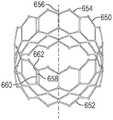
图1是假体心脏瓣膜的示例性实施例的透视图。1 is a perspective view of an exemplary embodiment of a prosthetic heart valve.
图2是根据另一实施例的用于假体心脏瓣膜的框架的透视图,该框架包括三个扩展锁定机构。2 is a perspective view of a frame for a prosthetic heart valve including three expanded locking mechanisms, according to another embodiment.
图3是图2的框架和扩展锁定机构的俯视图。FIG. 3 is a top view of the frame and extension locking mechanism of FIG. 2 .
图4是根据一个实施例的用于假体心脏瓣膜的具有锥形形状的框架的侧视图。4 is a side view of a frame having a tapered shape for a prosthetic heart valve, according to one embodiment.
图5是假体心脏瓣膜的框架的另一实施例的侧视图,该框架具有锥形形状。5 is a side view of another embodiment of a frame of a prosthetic heart valve, the frame having a tapered shape.
图6是用于假体心脏瓣膜的示例性小叶的平面图。6 is a plan view of an exemplary leaflet for a prosthetic heart valve.
图7是假体心脏瓣膜的合缝的一个实施例的剖视俯视图,其中,该合缝被固定到假体心脏瓣膜的支撑柱。7 is a cross-sectional top view of one embodiment of a commissure of a prosthetic heart valve, wherein the commissure is secured to a support post of the prosthetic heart valve.
图8是图7的支撑柱的内侧的前透视图,其中图7的合缝被固定到支撑柱。8 is a front perspective view of the inside of the support post of FIG. 7 with the seam of FIG. 7 secured to the support post.
图9是图7的支撑柱的外侧的后透视图,其中图7的合缝被固定到支撑柱。9 is a rear perspective view of the outside of the support post of FIG. 7 with the seam of FIG. 7 secured to the support post.
图10是根据一个实施例的假体心脏瓣膜的透视图,该假体心脏瓣膜包括具有打开的合缝窗口的框架。10 is a perspective view of a prosthetic heart valve including a frame with an open commissure window, according to one embodiment.
图11是包括打开的合缝窗口的假体心脏瓣膜的示例性框架的透视图。11 is a perspective view of an exemplary frame of a prosthetic heart valve including an open commissural window.
图12是合缝支撑元件和假体心脏瓣膜的框架的相应致动器组件的实施例的透视图,该实施例适于接收合缝支撑元件。12 is a perspective view of an embodiment of a commissure support element and a corresponding actuator assembly of a frame of a prosthetic heart valve adapted to receive the commissure support element.
图13是联接到相应的致动器组件的图12的合缝支撑元件的实施例的透视图。13 is a perspective view of an embodiment of the suture support element of FIG. 12 coupled to a corresponding actuator assembly.
图14是图7的合缝的实施例的剖视俯视图,其中,合缝被固定到假体心脏瓣膜的框架的打开的合缝窗口或被构造成联接到框架的合缝支撑元件。14 is a cross-sectional top view of an embodiment of the commissure of FIG. 7, wherein the commissure is secured to an open commissure window of a frame of a prosthetic heart valve or a commissure support element configured to be coupled to the frame.
图15是图7的合缝的实施例的详细透视图,其中合缝被固定到假体心脏瓣膜框架的小格上。Figure 15 is a detailed perspective view of an embodiment of the commissure of Figure 7, wherein the commissure is secured to the cells of the prosthetic heart valve frame.
图16是包括图15的合缝的示例性假体心脏瓣膜的侧视图。FIG. 16 is a side view of an exemplary prosthetic heart valve including the commissure of FIG. 15 .
图17是用于组装包括多个小叶的假体心脏瓣膜的方法的流程图。17 is a flowchart of a method for assembling a prosthetic heart valve including a plurality of leaflets.
图18是在小叶的合缝突片处具有相对直的针脚线的第一实施例的示例性小叶的一部分的细节图。18 is a detail view of a portion of an exemplary leaflet of the first embodiment with relatively straight stitch lines at the commissural tabs of the leaflets.
图19是其中在合缝突片处针脚线的一部分从针脚线的其余部分偏移的针脚线的第二实施例的示例性小叶的一部分的细节图。19 is a detail view of a portion of an exemplary leaflet of a second embodiment of a stitching line in which a portion of the stitching line is offset from the remainder of the stitching line at the stitching tab.
图20是其中在合缝突片处针脚线的一部分从针脚线的其余部分偏移的针脚线的第三实施例的示例性小叶的一部分的细节图。20 is a detail view of a portion of an exemplary leaflet of a third embodiment of a stitching line with a portion of the stitching line offset from the rest of the stitching line at the stitching tab.
图21是用于将假体心脏瓣膜输送到目标植入部位的经导管输送设备的实施例的侧视图,其中假体心脏瓣膜在径向压缩状态下保持在输送设备的胶囊/ 小容器(capsule)内。21 is a side view of an embodiment of a transcatheter delivery device for delivering a prosthetic heart valve to a target implantation site, wherein the prosthetic heart valve is held in a capsule/capsule of the delivery device in a radially compressed state. )Inside.
图22是图21的经导管输送设备的侧视图,其中将胶囊缩回以露出假体心脏瓣膜。22 is a side view of the transcatheter delivery device of FIG. 21 with the capsule retracted to expose the prosthetic heart valve.
具体实施方式Detailed ways
出于描述的目的,本文描述了本文公开的实施例的某些方面、优点和新颖特征。所描述的方法、系统和设备不应以任何方式解释为限制性的。取而代之,本公开涉及各种公开的实施例的所有新颖的和非显而易见的特征和方面(单独地和与彼此的各种组合和子组合)。所公开的方法、系统和设备不限于任何特定方面、特征或它们的组合,所公开的方法、系统和设备也不要求存在任何一个或多个特定优点或待解决的问题。For the purpose of description, certain aspects, advantages, and novel features of the embodiments disclosed herein are described herein. The described methods, systems and apparatus should not be construed as limiting in any way. Instead, the present disclosure relates to all novel and non-obvious features and aspects of the various disclosed embodiments (individually and in various combinations and subcombinations with each other). The disclosed methods, systems, and apparatus are not limited to any particular aspect, feature, or combination thereof, nor do the disclosed methods, systems, and apparatus require any one or more particular advantages or problems to be solved.
结合本实用新型的特定方面、实施例或示例描述的特征、整数、特性、化合物、化学部分或组应理解为适用于本文所述的任何其他方面、实施例或示例,除非与其不相容。本说明书中公开的所有特征(包括任何随附的权利要求书、摘要和附图)和/或如此公开的任何方法或过程的所有步骤可以以任何组合进行组合,除非其中至少有一些这样的特征和/或步骤的组合是互斥的。本公开不限于任何前述实施例的细节。本公开扩展到本说明书中公开的特征的任何新颖的一个或任何新颖的组合(包括任何所附权利要求、摘要和附图),或扩展到如此公开的任何方法或过程的步骤的任何新颖的一个或任何新颖的组合。Features, integers, characteristics, compounds, chemical moieties or groups described in connection with a particular aspect, embodiment or example of the invention are to be understood to be applicable to any other aspect, embodiment or example described herein unless incompatible therewith. All features disclosed in this specification (including any accompanying claims, abstract and drawings) and/or all steps of any method or process so disclosed may be combined in any combination unless there are at least some of such features and/or combinations of steps are mutually exclusive. The present disclosure is not limited to the details of any preceding embodiments. The present disclosure extends to any novel one or any novel combination of features disclosed in this specification (including any accompanying claims, abstract and drawings), or to any novel steps of any method or process so disclosed one or any novel combination.
尽管为了便于呈现,以特定的顺序性次序描述了所公开方法中的一些的操作,但是应当理解,这种描述方式涵盖重新排列,除非以下阐述的具体语言要求特定的次序。例如,在某些情况下,顺序性描述的操作可被重新排列或同时执行。此外,为了简洁起见,附图可能未显示可将所公开的方法、系统和设备与其它系统、方法和设备结合使用的各种方式。Although the operations of some of the disclosed methods have been described in a specific sequential order for ease of presentation, it is to be understood that rearrangement is contemplated by this manner of description, unless specific language set forth below requires a specific order. For example, in some cases operations described sequentially may be rearranged or performed concurrently. Furthermore, for the sake of brevity, the figures may not show the various ways in which the disclosed methods, systems, and devices may be used in conjunction with other systems, methods, and devices.
如本文所用,术语“一”、“一个”和“至少一个”涵盖指定元件中的一个或多个。也就是说,如果存在特定元件中的两个,则这些元件中的一个也会存在,因此存在“一个”元件。术语“多个”和“复数”是指特定元件中的两个或更多个。As used herein, the terms "a," "an," and "at least one" encompass one or more of the specified elements. That is, if two of a particular element are present, one of the elements will also be present, so there is "an" of the element. The terms "plurality" and "plurality" refer to two or more of a specified element.
如本文所用,在元件列表的最后两个之间使用的术语“和/或”是指所列出的元件中的任何一个或多个。例如,短语“A、B和/或C”表示“A”、“B”、“C”、“A和B”、“A和C”、“B和C”或“A、B和C”。As used herein, the term "and/or" used between the last two of a list of elements refers to any one or more of the listed elements. For example, the phrase "A, B and/or C" means "A", "B", "C", "A and B", "A and C", "B and C" or "A, B and C" .
如本文中所使用,术语“联接”通常是指物理上联接或链接,并且不排除在没有特定相反语言的情况下在联接项之间存在中间元件。As used herein, the term "coupled" generally refers to physically coupled or linked, and does not preclude the presence of intervening elements between coupled items in the absence of specific language to the contrary.
方向和其他相对参考(例如,内、外、上、下等)可用于促进本文中的附图和原理的讨论,但并不意图是限制性的。例如,可以使用某些术语,诸如“内侧”、“外侧”、“顶部”、“下”、“内部”、“外部”等。当处理相对关系时,尤其是相对于所示出的实施例,这种术语在适用时用于提供一些描述的清晰度。但是,这些术语并非旨在暗示绝对的关系、位置和/或取向。例如,相对于物体,只需将物体翻转过来,“上”部就可以简单地变成“下”部。但是,它仍然是相同的部分,并且物体仍然相同。如本文所用,“和/或”是指“和”或“或”以及“和”和“或”。Orientation and other relative references (eg, inside, outside, upper, lower, etc.) may be used to facilitate discussion of the figures and principles herein, but are not intended to be limiting. For example, certain terms such as "inner", "outer", "top", "lower", "inner", "outer" and the like may be used. When dealing with relative relationships, particularly with respect to the illustrated embodiments, such terminology is used, where applicable, to provide some clarity of description. However, these terms are not intended to imply an absolute relationship, position and/or orientation. For example, with respect to an object, the "upper" part can simply become the "lower" part by simply flipping the object over. However, it's still the same parts, and the objects are still the same. As used herein, "and/or" means "and" or "or" as well as "and" and "or."
如本文所使用的,关于假体心脏瓣膜和输送设备,“近侧”是指部件的更靠近使用者和/或患者外侧的输送设备的手柄的位置、方向或部分,而“远侧”是部件的指远离使用者和/或输送设备的手柄并且更靠近植入部位的位置、方向或部分。除非另外明确定义,术语“纵向”和“轴向”是指沿近侧和远侧方向延伸的轴线。此外,术语“径向”是指垂直于轴线布置并且沿着自物体的中心的半径指向的方向(其中轴线位于中心,诸如假体瓣膜的纵向轴线)。As used herein, with respect to prosthetic heart valves and delivery devices, "proximal" refers to the location, orientation, or portion of the component of the delivery device that is closer to the outside of the user and/or patient, while "distal" is A component refers to a location, direction or portion that is further away from the user and/or the handle of the delivery device and closer to the implantation site. Unless explicitly defined otherwise, the terms "longitudinal" and "axial" refer to axes extending in proximal and distal directions. Furthermore, the term "radial" refers to a direction arranged perpendicular to the axis and pointing along a radius from the center of the object (where the axis is centrally located, such as the longitudinal axis of a prosthetic valve).
公开技术的示例Examples of disclosed technology
这里描述的是假体心脏瓣膜、小叶组件和假体心脏瓣膜的合缝的示例以及组装假体心脏瓣膜的合缝的方法。假体心脏瓣膜可包括环形框架和经由通过接合小叶的成对的相邻端部(在本文中称为合缝突片)而形成的合缝而附接至框架的多个小叶。合缝的形成可以包括将第一小叶的第一合缝突片和相邻的第二小叶的第二合缝突片中的每一个折叠成在横向方向上重叠的两个重叠层,该横向方向垂直于相对于环形框架的中心纵向轴线的轴向方向和径向方向布置。合缝的形成还包括将折叠的第一合缝突片抵靠附接构件的突出部分的第一侧布置,并且将折叠的第二合缝突片抵靠突出部分的相反的第二侧布置,突出部分在径向方向上远离附接构件的基部延伸。在一些实施例中,附接构件可以是柔性织物或聚合物材料。合缝的形成还包括,将第一合缝突片和第二合缝突片中的每一个固定到附接构件并且然后将附接构件直接地或经由构造成联接至合缝支撑部的合缝支撑元件附接至框架的相应合缝支撑部。Described herein are examples of prosthetic heart valves, leaflet assemblies, and prosthetic heart valve commissures, as well as methods of assembling prosthetic heart valve commissures. The prosthetic heart valve may include an annular frame and a plurality of leaflets attached to the frame via commissures formed by commissural paired adjacent ends of the leaflets (referred to herein as commissural tabs). The forming of the commissure may include folding each of the first commissural tab of the first leaflet and the second commissural tab of the adjacent second leaflet into two overlapping layers that overlap in a lateral direction, the lateral The directions are arranged perpendicular to the axial and radial directions relative to the central longitudinal axis of the ring frame. Forming the seam also includes disposing the folded first seam tab against a first side of the protruding portion of the attachment member, and disposing the folded second seam tab against an opposite second side of the protruding portion , the protruding portion extends away from the base of the attachment member in the radial direction. In some embodiments, the attachment member may be a flexible fabric or polymeric material. Forming the commissure also includes securing each of the first commissure tab and the second commissure tab to the attachment member and then attaching the attachment member directly or via a stitch configured to couple to the commissure support. Seam support elements are attached to corresponding seam supports of the frame.
在一些实施例中,附接构件的基部可以在径向方向上布置在折叠的第一和第二合缝突片和合缝支撑部或合缝支撑元件之间。结果,可以阻止小叶的合缝突片与框架接触。这种合缝构造可以减小瓣膜操作期间以及框架的径向扩展和/或收缩期间小叶上的应力,从而增加其寿命。In some embodiments, the base of the attachment member may be disposed in the radial direction between the folded first and second commissure tabs and the commissure support or commissure support element. As a result, the commissural tabs of the leaflets can be prevented from contacting the frame. Such a commissural configuration may reduce stress on the leaflets during valve operation and during radial expansion and/or contraction of the frame, thereby increasing its longevity.
图1示出了根据一个实施例的示例性假体心脏瓣膜10。假体心脏瓣膜10 可在用于输送到患者体内的径向压缩的构造和径向扩展的构造(如图1所示) 之间径向可压缩和可扩展。在特定实施例中,假体心脏瓣膜10可以被植入在天然的主动脉瓣膜环内,尽管它也可以被植入在心脏的其他位置,包括植入在天然二尖瓣内、天然的肺动脉瓣和天然的三尖瓣内。假体心脏瓣膜10可包括具有第一端14和第二端16的环形支架或框架12。FIG. 1 shows an exemplary
在所描绘的实施例中,第一端14是流入端,并且第二端16是流出端。流出端16可联接至输送设备,以经股逆行输送方法将假体心脏瓣膜输送和植入假体心脏瓣膜内。因此,在假体心脏瓣膜的输送构造中,流出端16是假体瓣膜的最近端。在另一些实施例中,取决于要更换的特定天然瓣膜和所使用的输送技术(例如,经中隔、经心尖等),流入端14可以联接至输送设备。例如,当经由经中隔输送方法将假体心脏瓣膜输送至天然二尖瓣时,流入端 14可联接至输送设备(因此在输送构造中为假体心脏瓣膜的最近端)。可用于输送假体心脏瓣膜的示例性输送设备在图21和图22中示出并在下面更详细地描述。In the depicted embodiment, the
返回图1,框架12可以由各种合适的材料中的任意种制成,例如不锈钢、钴铬合金或镍钛合金(“NiTi”),例如镍钛诺。再次参考图1,如图所示,框架12可包括以格子型图案布置的多个互连的支柱28。示出的支柱28在假体心脏瓣膜10处于扩展构造时相对于假体心脏瓣膜10的纵向轴线倾斜地设置,或者相对于假体心脏瓣膜10的纵向轴线以一定角度偏移,并且从假体心脏瓣膜10的纵向轴线径向偏移。在另一些实施例中,支柱28可以偏移与图1中所描绘的不同的量,或者支柱28中的一些或全部可以平行于假体心脏瓣膜10 的纵向轴线定位。Returning to FIG. 1 , the
在所示的实施例中,支柱28沿着每个支柱的长度在一个或多个枢转接头处可枢转地彼此联接。例如,在示出的构造中,每个支柱28可形成有在支柱的相对端处的孔和沿着支柱的长度间隔开的孔。各个铰链可形成在支柱28通过紧固件或枢轴构件(诸如延伸穿过孔的铆钉或销30)彼此重叠的位置处。当框架12径向扩展或压缩时,例如在假体心脏瓣膜10的组装、准备或植入期间,铰链可允许支柱28相对于彼此枢转。In the embodiment shown, the
在一些实施例中,框架12可以通过形成单独的部件(例如,框架的支柱和紧固件),然后将单独的部件机械地组装和连接在一起而构造。在另一些实施例中,支柱28不通过相应的铰链彼此联接,而是相对于彼此可枢转或可弯曲以允许框架12的径向扩展和收缩。例如,可以由单片材料(例如金属管) 形成框架12(例如,通过进行激光切割、电铸或物理气相沉积)。在美国专利申请公开号2018/0153689、2018/0344456和2019/0060057中描述了有关框架和假体心脏瓣膜的构造的更多细节,在此通过引用将其全部并入。In some embodiments, the
假体心脏瓣膜10还可以包括瓣膜结构18,该瓣膜结构18联接至框架12 并且构造成调节从流入端14到流出端16通过假体心脏瓣膜10的血液流动。假体心脏瓣膜10还可以包括多个致动器80,这些致动器80安装到框架12的内表面并且围绕框架12的内表面等距分布。致动器被构造成向框架施加扩展和压缩,以径向地扩展和压缩假体瓣膜。The
在所示的实施例中,致动器80是线性致动器,每个致动器均包括内部构件或活塞90以及外部构件或圆柱体92。内部构件90可枢转地联接至框架的接合处,诸如在第一端14处,而外部构件92在第二端16附近可枢转地联接至框架的另一接合处。使内部构件90相对于外部构件92向近侧移动和/或使外部构件92相对于内部构件90向远侧移动有效地使假体瓣膜径向扩展。相反,使内部构件90相对于外部构件92向远侧运动和/或使外部构件92相对于内部构件90向近侧运动有效地使假体瓣膜径向压缩。致动器80可以包括锁定机构,该锁定机构被配置为将假体瓣膜保持在患者体内的扩展状态。In the embodiment shown, the
在一些实施例中,每个致动器80可以被配置为与经导管输送系统的输送设备的一个或多个相应的致动器形成可释放的连接。输送设备的致动器可以将力从输送设备的手柄传递到致动器80,以使假体瓣膜扩展或压缩。在美国专利申请公开号2018/0153689、2019/0060057和2018/0325665中可以找到致动器、锁定机构和用于致动致动器的输送设备的更多细节,在此通过引用将其全部内容并入本文。可以将在先前提交的申请中公开的任何致动器和锁定机构并入本文公开的任何假体瓣膜中。此外,在先前提交的申请中公开的任何输送设备都可以用于输送和植入本文公开的任何假体瓣膜。In some embodiments, each actuator 80 may be configured to form a releasable connection with one or more corresponding actuators of a delivery device of a transcatheter delivery system. An actuator of the delivery device can transmit force from the handle of the delivery device to the
在一些实施例中,每个致动器80可用于支撑相应的合缝24(如下所述)。这样,致动器80可包括用于将瓣膜结构18的合缝24支撑和附接到框架12 的合缝支撑部,如本文中进一步描述的。In some embodiments, each actuator 80 may be used to support a corresponding commissure 24 (described below). As such, the
瓣膜结构18可包括例如小叶组件,该小叶组件包括由柔性材料制成的一个或多个小叶22(在所示实施例中为三个小叶22)。小叶组件的小叶22可以全部或部分地由生物材料、生物相容性合成材料或其他此类材料制成。合适的生物材料可以包括例如牛心包(或来自其他来源的心包)。每个小叶22包括布置在小叶的主体的相反侧上的两个相对的合缝突片。小叶的主体可以是小叶的适于在假体心脏瓣膜10的操作期间弯曲和移动的部分。相邻小叶22 的合缝突片可以布置成形成合缝24,其例如可以被安装在各个致动器80的合缝支撑部。关于经导管假体心脏瓣膜的更多细节,包括将瓣膜结构连接至假体心脏瓣膜10的框架12的方式,例如,可以在美国专利号6,730,118、7,393,360、 7,510,575、7,993,394和8,652,202以及美国专利申请公开号2018/0325665中找到,其全部内容通过引用整体并入本文。The
在一些实施例中,如图1所示,合缝24可以通过合缝附件26直接安装 (例如缝合)至框架12的致动器80的合缝支撑部。作为一个示例,合缝附件26可以包括将合缝24固定至相应的致动器80的一个或多个针脚。在另一些实施例中,合缝24经安装以支撑与致动器80分离的框架的支柱或柱。在另一些实施例中,可将合缝固定至另外的合缝附件或支撑构件(如本文进一步描述的)并且然后将支撑构件固定到致动器80的合缝支撑部或框架的支撑支柱或柱。In some embodiments, as shown in FIG. 1 , the
假体心脏瓣膜10还可包括一个或多个裙部或密封构件。例如,如图1所示,假体心脏瓣膜10可包括安装在框架12的内表面上的内裙部20。如图1 所示,内裙部20是横跨框架12的内表面的整个圆周的周向内裙部。内裙部 20可以用作密封构件,以防止或减少瓣周漏(例如,当将瓣膜放置在植入部位时)并将其作为将小叶22锚定到框架12的附接表面。例如,小叶22的流入(尖端)边缘可直接缝合到内裙部20,内裙部20进而可(例如,用缝线) 直接连接至框架的选定支柱28,如图1所示。The
假体心脏瓣膜10还可以包括安装在框架12的外表面上的外裙部(图1 中未示出)。外裙通过抵靠天然瓣膜环的组织进行密封并有助于减少通过假体瓣膜的瓣周漏而可以用作假体瓣膜的密封构件。内裙部和外裙部可以由各种合适的生物相容性材料中的任意种形成,包括各种合成材料(例如,PET)或天然组织(例如,心包组织)中的任意种。内裙部和外裙部可使用缝线、粘合剂、焊接和/或用于将裙部附接到框架的其他方式安装到框架。The
图2和图3示出了假体瓣膜100的示例性实施例,根据另一实施例,假体瓣膜100包括框架102和一个或多个扩展锁定机构150。框架102包括多个可枢转地连接的支柱104,其限定了流入端106(其在所示实施例的输送构造中是框架的远端)和流出端108(其在所示实施例的输送构造中是框架的近端)。支柱104在多个接合处彼此可枢转地连接,如上文结合假体瓣膜10所述,当框架102被径向压缩和扩展时,允许支柱相对于彼此枢转。FIGS. 2 and 3 illustrate an exemplary embodiment of a
假体瓣膜100可以包括瓣膜结构(例如,瓣膜结构18)以及内裙部和/或外裙部,如先前所描述的,尽管这些部件为了说明的目的从图2和3中省略。可以使用一个或多个扩展锁定机构150来代替上述致动器80或除上述致动器 80之外使用。扩展锁定机构150可用于将假体瓣膜100的框架102径向扩展和锁定在径向扩展状态。在一些实施例中,小叶的合缝可以附接到扩展锁定机构150的合缝支撑部。在替代实施例中,小叶的合缝可以附接到框架102 的另外的合缝柱。
图2示出了安装到框架102的三个扩展锁定机构150,其中框架102被示出为处于径向扩展构造。尽管所示的实施例示出了围绕框架的圆周彼此间隔开的三个扩展锁定机构150,但是应当指出,假体瓣膜可以包括任意数量的扩展锁定机构150。例如,在一些实施例中,假体瓣膜可包括单个扩展锁定机构,或两个扩展锁定机构,或四个扩展锁定机构等。扩展锁定机构150可放置在围绕框架102的圆周的任何位置。例如,在一些实施例中,诸如,所示的实施例,扩展锁定机构150围绕框架102的圆周彼此等距间隔开。在另一些实施例中,具有邻近彼此定位的两个或更多扩展锁定机构可以是有利的。Figure 2 shows three
每个扩展锁定机构150可包括呈具有内腔、空腔或钻孔的套筒152形式的外部构件,以及至少部分地延伸入腔中的内部构件156。在所示实施例中,套筒152包括内壁186、外壁188和两个侧壁190,每个侧壁在内壁186的纵向边缘和外壁188的相对的纵向边缘之间径向延伸。内壁186、外壁188和两个侧壁190限定空腔,空腔的尺寸和形状设计成可接收内部构件156。Each
在所示实施例中,套筒152的横截面为矩形,而内部构件156的横截面为与钻孔的形状相对应的矩形。在另一些实施例中,套筒152和/或内部构件 156可具有正方形的横截面轮廓。如图3所示,矩形和/或正方形横截面可有利地最小化扩展锁定构件延伸到框架102的内腔中的距离,这可减小瓣膜100 的总体卷曲轮廓。然而,在另一些实施例中,套筒和内部构件的横截面可以具有各种相应的形状中的任意种,例如圆形、卵形、三角形、矩形、正方形或它们的组合。In the illustrated embodiment, the cross-section of the
如图1中最佳所示,内部构件156的远端部分158可以通过紧固件160 在第一位置处联接到框架102,该紧固件160固定到内部构件156的远端部分 158并从其径向延伸。紧固件160可以例如是铆钉或销。如图所示,在一些实施例中,紧固件160可以延伸穿过框架102的两个重叠的支柱104的接合处的相应的孔,并且可以用作枢转销,两个支柱104可以围绕该枢转销相对于彼此和内部构件156枢转。在一些实施例中,端盖或螺母162(如图3所示)可以设置在紧固件160的端部上方。螺母162的直径可以大于孔的直径以将紧固件160保持在孔内。在替代实施例中,内部构件156不需要包括紧固件 160,并且可以经由其他附接方式(例如,焊接、粘合剂等)联接至框架102。As best shown in FIG. 1 , the
套筒152可以在第二位置处联接至框架102,该第二位置与第一位置轴向间隔开。例如,在所示的实施例中,内部构件156在靠近框架的远端或流入端106处固定到框架102,并且套筒152在靠近框架的近端或流出端108或在框架的近端或流出端108处诸如通过紧固件161(例如,铆钉或销)固定到框架102。紧固件161在两个重叠的支柱104的接合处通过相应的孔固定到套筒 152并从套筒152径向延伸,并且可以用作枢转销,两个支柱104可以围绕枢转销相对于彼此和套筒152枢转。可以将螺母162安装在每个紧固件161上,以将紧固件保持在相应的孔内。扩展锁定机构150可以在框架上的任何两个轴向间隔开的、周向对准的位置处可枢转地联接到框架102。The
内部构件156可以沿着框架102的中心纵向轴线在近侧方向和远侧方向上相对于套筒152轴向可移动。这样,因为内部构件156和套筒152以轴向间隔开的位置被固定到框架,将内部构件156和套筒152以伸缩的方式相对于彼此轴向移动可以引起框架102的径向扩展或压缩。例如,将内部构件156 朝向框架的流出端108向近侧移动,同时将套筒152保持在固定位置和/或将套筒152朝向框架的流入端106向远侧移动,可将框架102轴向缩短并径向扩展。相反地,向远侧移动内部构件156和/或向近侧移动套筒152使框架102 轴向伸长并径向压缩。The
包括一个或多个扩展锁定机构150的假体瓣膜100可以按以下示例性方式扩展。通常,将假体瓣膜100置于径向压缩状态并且可释放地联接至输送设备的远端部分,然后将其穿过患者的脉管系统前进至选定的植入部位(例如,天然主动脉瓣膜环)。然后,可以使用扩展锁定机构150将假体瓣膜100 部署在植入部位并扩展和锁定在扩展构造。关于假体瓣膜、扩展锁定机构以及用于致动扩展锁定机构的输送设备的更多细节可以在国际申请号 PCT/US2020/057691中找到,其内容通过引用并入本文。A
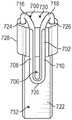
图21和22示出了根据一个实施例的、适于将假体心脏瓣膜(或假体瓣膜)1208(诸如,如上所述,图1所示的假体心脏瓣膜10和图2至图3中所示的假体瓣膜100)输送到患者体内的目标植入部位的输送设备1200。图21-22 示出了在瓣膜植入过程期间相对于输送设备1200处于不同构造的假体瓣膜 1208。假体瓣膜1208能够可释放地联接至输送设备1200的一个或多个部件,如上文和下文所述。应当理解,输送设备1200可以用于植入除假体瓣膜之外的假体装置,例如支架或移植物。21 and 22 illustrate a prosthetic heart valve (or prosthetic valve) 1208, such as, as described above,
所示实施例中的输送设备1200通常包括手柄1202、从手柄1202向远侧延伸的细长轴1204(在所示实施例中包括外轴或最外轴)、内(例如,最内) 轴1210、与外轴1204和内轴1210同轴布置并且在它们之间(例如,在径向方向上其垂直于输送设备1200的中心纵向轴线1230)的中间轴1224和至少一个致动器组件(例如,构件或致动器)1206以扩展和压缩假体瓣膜1208,至少一个致动器组件1206延伸穿过外轴1204并从外轴1204的远端部分1212向外向远侧延伸。The
在一些实施例中,外轴1204、内轴1210、中间轴1224和/或致动器组件 1206可以组成由手柄1202控制并附接到手柄1202的输送设备1200的输送设备导管。In some embodiments,
输送设备1200可包括可释放地联接至假体瓣膜1208的三个致动器组件 1206(在图21-22中仅示出了三个致动器组件中的两个致动器组件)。然而,在替代实施例中,输送设备1200可包括多于或少于三个致动器组件1206(例如,一个、两个、四个等)。如图21-22所示,多个致动器组件1206围绕输送设备1200的圆周在周向上彼此间隔开,并且可以轴向地穿过外轴1204从手柄1202延伸至假体瓣膜1208。
在特定实施例中,每个致动器组件1206可以可释放地联接到假体瓣膜的对应致动器(例如,如图1所示的致动器80或如图2和图3所示的扩展锁定机构150的一部分)。每个致动器组件1206可包括内部构件和外部构件,该内部构件具有可释放地联接至假体瓣膜的致动器的内部构件的远端,外部构件具有可释放地联接至假体瓣膜的致动器的外部构件的远端。在另一个实施例中,每个致动器组件1206可以是经由螺纹套筒可释放地联接至假体瓣膜 1208的致动器组件。In certain embodiments, each
在一些实施例中,中间轴1224可适于容纳致动器组件1206和并使其有条理。例如,致动器组件1206可被容纳在中间轴1224的远端内并从远端向外延伸。在一些实施例中,每个致动器组件1206可以与中间轴1224内的其他致动器组件1206保持分离。例如,每个致动器组件1206可以延伸穿过中间轴1224的单独的内腔。In some embodiments, the
如图21-22所示,内轴1210的远端可以包括前锥体(nosecone)1214,前锥体1214可以用于引导输送设备1200穿过患者的内腔到达用于假体瓣膜 1208的目标植入部位。可以邻近假体瓣膜1208的远端1226布置前锥体1214。21-22, the distal end of the
在使用中,输送设备1200可以可释放地联接至假体瓣膜1208,以产生假体瓣膜1208的框架的径向扩展和压缩。在一些实施例中,可以配置输送设备 1200的致动器组件1206,从而将推力和/或拉力从输送设备1200的手柄1202 传递到假体瓣膜1208。例如,在一些实施例中,致动器组件1206可以具有远端部分,该远端部分可以通过相应的释放锁定单元可释放地连接到假体瓣膜 1208。In use, the
在一些实施例中,输送设备1200的外轴1204可以被配置为具有可调节曲率的可操纵导向导管,以用于操纵输送设备1200通过患者的脉管系统。在特定的实施例中,外轴1204可以包括可操纵的远端部分,该远端部分的曲率可以由操作员调节以帮助引导设备通过患者的脉管系统。In some embodiments, the
外轴1204和致动器组件1206可以相对于彼此(轴向和/或旋转地)移动,以利于假体瓣膜1208在患者体内的植入部位进行输送和定位。The
在一些实施例中,外轴1204的远端部分1212可以形成和/或用作鞘管(或胶囊)1222,鞘管和/或胶囊的尺寸和形状设置成以径向压缩状态接收和容纳假体瓣膜1208,以用于输送入并通过患者的脉管系统。一旦假体瓣膜1208被推进至植入部位或邻近植入部位,就可以通过使外轴1204缩回并且因而使胶囊1222沿中心纵向轴线1230相对于致动器组件1206和假体瓣膜1208轴向缩回,从而使假体瓣膜1208从胶囊1222推进。这样,当胶囊1222轴向朝向手柄1202(例如,沿着中心纵向轴线1230在近侧方向上)向后移动时,就可以露出假体瓣膜1208。在替代实施例中,可通过相对于外轴1204推进致动器组件1206而将假体瓣膜1208从胶囊1222推进,此后可使假体瓣膜1208径向扩展。In some embodiments, the
通过相对于外轴1204轴向移动致动器组件1206或通过相对于致动器组件1206缩回外轴1204,可以通过操作手柄1202上的第一旋钮1216来致动假体瓣膜1208从鞘管中的前进。第一旋钮1216可以可操作地连接到外轴1204 的近端部分,并且可以配置成相对于致动器组件1206向近侧缩回外轴1204,以从胶囊1222的远端部分1212展开假体瓣膜1208或可操作地连接到致动器组件1206的近端,以相对于外轴1204向远侧推进致动器组件1206,以从胶囊1222的远端部分1212展开假体瓣膜1208。第一旋钮1216可以是操作地连接到致动器组件1206和/或外轴1204的可滑动或旋转调节元件。
手柄1202可包括另外的调节旋钮,诸如第二旋钮1218和第三旋钮1220,如图21至图22所示。在一些实施例中,第二旋钮1218可以被操作地联接至致动器组件1206,并且致动致动器组件1206以将假体瓣膜1208从非扩展(或径向压缩)构造(如图21所示)调节至径向扩展构造,反之亦然。The
在一些实施例中,第三旋钮1220可以操作地联接至致动器组件1206,并且致动致动器组件1206以与假体瓣膜1208断开连接。结果,可以将假体瓣膜1208与输送设备1200分离,并在目标植入部位处植入(展开)。In some embodiments, the
图21示出了以径向压缩状态下保持在输送设备1200的胶囊1222内的假体瓣膜1208。因此,在图21中,假体瓣膜1208处于其具有最小直径D1的径向压缩构造。最小直径D1可以与胶囊1222的内径大致相同。胶囊1222围绕假体瓣膜1208的外侧,如图21所示,可将假体瓣膜维持在径向压缩构造。结果,假体瓣膜1208可以经由输送设备1200通过患者的脉管系统前进到例如目标植入部位。21 shows the
在到达目标植入部位之后,可以在沿着输送设备1200的中心纵向轴线 1230的近侧方向上将胶囊1222拉离前锥体1214和假体瓣膜1208(或从其缩回),以露出假体瓣膜1208。在替代实施例中,致动器组件1206可沿远侧方向前进,以将假体瓣膜1208移出胶囊1222。After reaching the target implantation site, the
图22示出了假体瓣膜1208处于未覆盖(出鞘)状态,其中假体瓣膜1208 被布置在胶囊1222的外侧。在这种状态下,假体瓣膜1208没有经由致动器组件1206主动地扩展。然而,由于其不再由胶囊1222环绕(例如,不再保持在胶囊1222中),则由于框架的支柱的固有弹性,假体瓣膜1208可具有大于最小直径D1的部分扩展的直径D2。应当注意的是,为了说明的目的,在图22中可能放大了假体瓣膜1208从压缩的最小直径D1(图21)到部分扩展的直径D2(图22)的扩展程度。在从胶囊1222展开之后,如图22所示,然后可以通过致动器组件1206的致动来使假体瓣膜1208径向扩展和植入。FIG. 22 shows the
现在转向图4和图5中所示的实施例,在一些实施例中,假体心脏瓣膜的框架可包括支柱,该支柱成形为在扩展时形成非圆柱形的形状。例如,这样的框架可以沿着相对于框架的中心纵向轴线的轴向方向成锥形。在一些实施例中,框架可以从流出端到流入端成锥形。Turning now to the embodiments shown in FIGS. 4 and 5, in some embodiments, the frame of the prosthetic heart valve may include struts that are shaped to form a non-cylindrical shape when expanded. For example, such a frame may be tapered in an axial direction relative to the central longitudinal axis of the frame. In some embodiments, the frame may taper from the outflow end to the inflow end.
图4示出了假体瓣膜200的另一实施例,该假体瓣膜200包括以其展开的径向扩展构造示出的框架202。假体瓣膜200可包括瓣膜结构(例如,瓣膜结构18)、内和/或外裙部,以及致动器(例如,图1的致动器80)或图2至图3的扩展锁定机构150,如前所述,尽管为了说明性目的从图4中省略了这些组件。框架202可具有限定框架202的流入端224的流入端部分204和限定框架202的流出端226的流出端部分206。假体瓣膜200可限定从流入端部分204延伸到流出端部分206的纵向轴线(中央纵向轴线)A和垂直于纵向轴线A的横向轴线B。虽然在图4中仅示出框架202的一侧,但是应当理解,框架202形成具有与所示部分相同的相反侧的环形结构。Figure 4 illustrates another embodiment of a
框架202包括以格子型图案布置的多个互连的支柱208。每个支柱可从框架202的流入端224完全延伸到框架的流出端226。因此,在所示的实施例中,框架202可以完全由从流入端224连续延伸到流出端226的支柱形成。在替代实施例中,框架202可以具有沿着框架的长度端对端连接的支柱。The
每个支柱208可包括多个孔,所述多个孔可沿每个支柱208的长度不等距地间隔开,从而限定了具有不相等长度的多个区段212。在所示的实施例中,每个支柱208的区段212的长度可以从框架202的流入端部分204到出口端部分206减小。在组装的框架202中,支柱208形成布置在多个周向延伸的小格行中的多个封闭小格,其中小格从流入端224到流出端226逐渐变小。在所示的实施例中,每个支柱208具有限定了四个区段112和三行小格的五个孔,三行小格包括第一行小格228、第二行小格230和第三行小格232其中小格228最大,小格230小于小格228,并且小格232小于小格230。Each
在另一些实施例中,每个支柱可具有更多或更少数量的孔,以限定不同数量的支柱区段和框架小格的行。例如,图5示出了假体瓣膜300(如下所述),其中每个支柱包括七个孔。In other embodiments, each strut may have a greater or lesser number of holes to define a different number of strut segments and rows of frame cells. For example, Figure 5 shows a prosthetic valve 300 (described below) in which each strut includes seven holes.
如图4所示,支柱区段的变化的长度还在可枢转地连接的支柱之间形成角度244、246、248、250,其中该角度从流入端224到流出端226逐渐增加。在替代实施例中,一个或多个区段可以具有不相等的长度并且一个或多个区段的长度可相等。As shown in FIG. 4 , the varying lengths of the strut segments also form
如图4所示,每个支柱208可相对于框架202的纵向轴线A成螺旋形弯曲以限定框架202的环形形状。螺旋弯曲为每个支柱208提供了凹入的径向内表面(面向纵向轴线A的表面)和相反的凸出的径向外表面(背离纵向轴线A的表面)。As shown in FIG. 4 , each
孔可以用于使用紧固件214将支柱208彼此连接,例如以上参照假体瓣膜10(图1)所述的那些紧固件。在另一些实施例中,可以省略孔210和/或紧固件214。例如,支柱208可以固定地彼此连接,例如通过焊接或粘合,或者通过从金属管激光切割框架的各个支柱。The holes may be used to connect the
如图所示,区段212可相对于彼此端对端连接地布置,其中相邻的端部通过中间区段218彼此互连。支柱208可具有(相对于区段212)扩大的端部部分220,扩大的端部部分220在框架202的流入和流出端224、226处形成顶点222。中间区段218和端部部分220中的每个可具有相应的孔,例如在其几何中心,用于接收紧固件214的孔。如图所示,每个区段212可在垂直于支柱208的总长度的方向上从相邻区段212略微横向偏移。在替代实施例中,区段212可以经布置而相对于彼此没有任何偏移。As shown, the
在所示实施例中,支柱208的每个区段212是弯曲的,使得支柱208的整体形状相对于横向轴线B(或平行于轴线B且垂直于轴线A的任何线)弯曲。In the illustrated embodiment, each
在特定实施例中,每个支柱208可具有从支柱的一端到支柱的另一端的连续且恒定的曲线。在另一些实施例中,每个区段212在平行于纵向轴线A 的平面中的投影可以是笔直的(即,除了相对于纵向轴线A的任何螺旋弯曲之外,每个区段112都是笔直的)并且每个区段112沿着支柱208的长度相对于相邻区段112的偏移量可以改变,使得支柱208的整体形状沿着其长度相对于横向轴线B(或平行于轴线B并且垂直于轴线A的任何线)弯曲;也就是说,从支柱的一端延伸到另一端并且与每个区段212相交的线相对于轴线B是弯曲的。可替代地,各个支柱区段212可以是直的并且以非零角度端对端彼此连接,以使得支柱208的整体形状相对于横向轴线B(或平行于轴线B且垂直于轴线A的任何线)沿着其长度弯曲。在另一些实施例中,框架的一个或多个支柱可沿其长度具有非恒定或可变的曲率(在这种情况下,支柱的曲率中心可随着其沿支柱的长度移动而变化)。In certain embodiments, each
如图4所示,每个支柱208可以弯曲并且布置成使得其相对于框架202 的流出端226是凸起的。因此,在所示的实施例中,每个支柱208具有面向框架的流出端226的凸起的第一纵向边缘236和面向框架的流入端224的凹入的第二纵向边缘238。由于支柱208的独特形状,由支柱形成的框架202具有非欧氏几何形状,特别是椭圆形几何形状(也称为黎曼几何形状)。As shown in FIG. 4 , each
如图4所示,在展开配置中,支柱208的曲率可以使框架202具有非圆柱形的锥形形状(例如,截头圆锥形、V形或Y形),其中流出端226具有大于流入端224的第二直径D2的第一直径D1。锥度可以被称为框架202的拔模角(draft angle),其可以是纵向轴线A和与框架的外表面相切画出的线C 之间的角度的量度。当植入患者的天然瓣膜环内时,相对于锥形形状产生的流入而言,较大的流出可以减小跨瓣膜的压力梯度,从而有助于改善血液动力学并降低瓣周漏的风险。As shown in FIG. 4 , in the deployed configuration, the curvature of the
在特定实施例中,线A和C之间的拔模角可以为至少2度、至少5度、至少10度、至少20度、至少30度、至少40度或至少50度。在特定实施例中,拔模角可以在2度和15度之间。在特定实施例中,流出直径D1与流入直径D2之比至少大于1、至少大于1.1、至少大于1.2、至少大于1.3、至少大于1.4或至少大于1.5。In particular embodiments, the draft angle between lines A and C may be at least 2 degrees, at least 5 degrees, at least 10 degrees, at least 20 degrees, at least 30 degrees, at least 40 degrees, or at least 50 degrees. In certain embodiments, the draft angle may be between 2 degrees and 15 degrees. In certain embodiments, the ratio of outflow diameter D1 to inflow diameter D2 is at least greater than 1, at least greater than 1.1, at least greater than 1.2, at least greater than 1.3, at least greater than 1.4, or at least greater than 1.5.
在一些实施例中,流出直径D1与流入直径D2之间存在2-3mm的差。在一个特定的示例中,流出直径D1为约30mm,流入直径D2为约27mm。在另一个示例中,流出直径D1为约31.5mm,流入直径D2为约29mm。在另一个示例中,流出直径D1为约24.5mm,而流入直径D2为约22mm。In some embodiments, there is a 2-3 mm difference between the outflow diameter Dl and the inflow diameter D2. In one specific example, the outflow diameter D1 is about 30 mm and the inflow diameter D2 is about 27 mm. In another example, the outflow diameter D1 is about 31.5 mm and the inflow diameter D2 is about 29 mm. In another example, the outflow diameter D1 is about 24.5 mm, and the inflow diameter D2 is about 22 mm.
在一些实施例中,当处于卷曲或径向压缩构造时,框架202可保持锥形形状,其中,流出端226的直径大于流入端224的直径,并且该框架在压缩构造中的拔模角可以大于当框架处于扩展构造时框架的拔模角。In some embodiments, the
图5示出了假体瓣膜300的另一实施例,该假体瓣膜300包括具有锥形形状的框架302(以其展开的径向扩展构造示出)。特别地,框架302具有正的拔模角(例如,假体瓣膜300的流出端326处的直径大于流入端324处的直径),从而使框架302从流出端326到流入端324成锥形。FIG. 5 shows another embodiment of a
假体瓣膜300类似于假体瓣膜200,除了假体瓣膜300具有框架302,在框架302中,每个支柱308包括七个孔310并且因此具有比假体瓣膜200的支柱更多的支柱区段和框架小格。框架302可以类似于图1的框架12和图2 至图3的框架102,因为这些框架的每个支柱还包括七个孔。
类似于假体瓣膜10和/或假体瓣膜100,假体瓣膜300可包括瓣膜结构(例如,瓣膜结构18)、内和/或外裙部以及致动器(例如,图1的致动器80)或扩展锁定机构(例如,图2-3的扩展锁定机构150),如前所述,尽管出于说明的目的而省略了这些组件。框架302可具有限定框架的流入端324的流入端部分304和限定框架的流出端326的流出端部分306。假体瓣膜可限定从流入端部分304延伸到流出端部分306的纵向轴线A和垂直于纵向轴线A延伸的横向轴线B。Similar to
框架302包括从框架302的流入端324延伸到流出端326的多个互连的支柱308。因此,在所示的实施例中,框架302可以完全由从流入端324连续延伸到流出端326的支柱形成。在替代实施例中,框架302可以具有沿着框架的长度端对端连接的支柱。The
每个支柱308可包括多个孔310。如图所示,孔310可沿着支柱308的长度不等间距地间隔,从而限定了具有不同长度的多个区段312。在所示的实施例中,支柱308包括区段312a、312b、312c、312d、312e和312f,其中区段 312a是最短的,并且每个随后的区段312b、312c、312d、312e和312f具有逐渐增大的长度。在组装的框架302中,支柱308形成以周向延伸的多行小格布置的多个封闭的小格,其中小格从流入端324到流出端326逐渐变大。在所示的实施例中,每个支柱308具有限定六个区段312和五行小格的七个孔310,五行小格包括第一行小格328、第二行小格330、第三行小格332、第四行小格334和第五行小格336,其中小格328最小,每行小格从流入端到流出端逐渐变大。Each
支柱的变化的长度还在可枢转地连接的支柱之间形成角度338、340、342、 346、348,其中该角度从流入端324到流出端326逐渐减小。The varying lengths of the struts also form
在替代实施例中,一个或多个区段可以具有不相等的长度,以及一个或多个区段可以具有相等的长度。例如,区段312a可以是最短的区段,区段312b、312c、312d、312e可以具有相等的长度,而区段312f可以是最长的区段。在另一些实施例中,孔310可以沿着每个支柱的长度等间距地间隔开,从而形成相等长度的区段。In alternate embodiments, one or more segments may be of unequal length, and one or more segments may be of equal length. For example,
如图5所示,每个支柱308可以相对于框架的纵向轴线A螺旋地弯曲以限定框架302的环形形状。螺旋弯曲为每个支柱提供了凹入的径向内表面(面向纵向轴线A的表面)和相反的凸出的径向外表面(背离纵向轴线A的表面)。As shown in FIG. 5 , each
孔310可用于使用诸如上述紧固件214之类的紧固件将支柱308彼此连接。The
每个支柱308可以是弯曲的或布置成使得其相对于框架302的流出端326 是凹入的。Each
在一些实施例中,由于支柱308的弹性以及重叠的支柱之间的连接,在框架的径向压缩和扩展期间,支柱的弯曲程度可以改变。In some embodiments, the degree of bending of the struts may vary during radial compression and expansion of the frame due to the elasticity of
与假体瓣膜200一样,在扩展构造中,支柱308的曲率可以使框架302 具有非圆柱形的锥形形状(例如,截头圆锥形、V形或Y形),其中,流出端 326具有大于流入端324的第二直径D2的第一直径D1。这种构造可以减小穿过假体瓣膜300的压力梯度并改善血液动力学。As with the
在特定实施例中,框架302中的线A和C之间的拔模角可以在2度和15 度之间。在特定实施例中,拔模角可以是至少2度、至少5度、至少10度、至少20度、至少30度、至少40度或至少50度。在特定实施例中,流出直径D1与流入直径D2之比至少大于1、至少大于1.1、至少大于1.2、至少大于1.4或至少大于1.5。In certain embodiments, the draft angle between lines A and C in
在一些实施例中,流出直径D1与流入直径D2之间存在2-3mm的差。在一个特定的示例中,流出直径D1为约30mm,流入直径D2为约27mm。在另一个示例中,流出直径D1为约31.5mm,流入直径D2为约29mm。在另一个示例中,流出直径D1为约24.5mm,而流入直径D2为约22mm。In some embodiments, there is a 2-3 mm difference between the outflow diameter Dl and the inflow diameter D2. In one specific example, the outflow diameter D1 is about 30 mm and the inflow diameter D2 is about 27 mm. In another example, the outflow diameter D1 is about 31.5 mm and the inflow diameter D2 is about 29 mm. In another example, the outflow diameter D1 is about 24.5 mm, and the inflow diameter D2 is about 22 mm.
关于具有具有锥形形状的框架的假体瓣膜的更多细节可以在2019年10 月18日提交的国际申请PCT/US2019/056865和2020年2月11日提交的美国专利申请16/788,090中找到,它们中的每一个均通过引用整体并入本文。More details on prosthetic valves with frames having tapered shapes can be found in International Application PCT/US2019/056865, filed Oct. 18, 2019, and
现在转向图6,示出了可以包括在假体心脏瓣膜的瓣膜结构(例如,图1 的假体心脏瓣膜10的瓣膜结构18)中的示例性小叶400。为了说明的目的,小叶400被平放。小叶400可包括具有尖端(流入)边缘部分404和406的主要部分(或主体)402。特别地,尖端边缘部分404和406可包括在小叶400 的最流入端部分408处连接在一起的第一(左)侧尖端边缘部分404和第二 (右)侧尖端边缘部分406。第一和第二尖端边缘部分404和406一起形成小叶400的扇贝线。Turning now to FIG. 6 ,
小叶400可以包括从主要部分402的相反侧延伸的合缝突片412和414。合缝突片可以被配置为与相邻的小叶的相应合缝突片接合以形成合缝,并且用于附接到假体心脏瓣膜的框架(例如,通过合缝的附接构件,如本文进一步所述)。流出边缘部分410在合缝突片412和414之间横跨小叶400延伸。Leaflet 400 may include
弯曲边缘部分416、418在合缝突片412和414中的相应一个与第一和第二尖端边缘部分404和406中的相应一个之间延伸并连接合缝突片412和414 中的相应一个与第一和第二尖端边缘部分404和406中的相应一个。每个弯曲边缘部分416、418在小叶400的任一侧上限定开口区域,在本文中称为窗口420、422。
如图6所示,第一和第二尖端边缘部分404和406中的每个从弯曲边缘部分416和418中的相应一个的底部边缘到流入端部分408成角度。第一和第二尖端边缘部分404和406中的每一个的上边缘在垂直于轴向方向布置的横向方向上布置在合缝突片412和414中的相应一个的外边缘的内侧,该轴向从流出边缘部分410延伸到流入端部分408,平行于小叶的中心线424。结果,小叶的整体形状从流出边缘部分410到流入端部分408成锥形。As shown in FIG. 6 , each of the first and second
在一些实施例中,小叶400的形状可被构造成使得合缝突片412和414 相对于轴向方向成角度,该轴向方向平行于在流出边缘部分410和流入端部分408之间延伸穿过小叶400的中心的中心线424。例如,如图6所示,每个合缝突片412、414的横向(上和下)边缘426和428可以与竖直方向(例如,中心线424)成角度θ。如图6所示,可以在中心线424和垂直于横向边缘 426和428延伸穿过合缝突片412、414的线450之间限定角度θ。In some embodiments, the shape of the
在一些实施例中,可以选择角度θ以匹配或类似于(例如,在所选择的有限范围内)假体心脏瓣膜的框架的拔模角。例如,如以上参考图4和5所述,框架可以从框架的流出端到流入端成锥形,从而形成由拔模角(图4和5 中的线A和C之间的角度)限定的框架的锥形形状。通过选择角度θ以匹配或接近匹配(例如,在框架的拔模角的5-10%以内或5%以内)框架的拔模角,可以减小集中在合缝的合缝突片处的应力,同时还允许在体内瓣膜操作期间(例如,在小叶的打开和关闭期间)小叶的足够打开。In some embodiments, the angle Θ may be selected to match or be similar to (eg, within a selected limited range) the draft angle of the frame of the prosthetic heart valve. For example, as described above with reference to Figures 4 and 5, the frame may be tapered from the outflow end to the inflow end of the frame to form a frame defined by a draft angle (the angle between lines A and C in Figures 4 and 5). The tapered shape of the frame. By selecting the angle θ to match or nearly match (eg, within 5-10% or within 5% of the draft angle of the frame) the draft angle of the frame, the stress concentrated at the commissure tabs of the commissure can be reduced , while also allowing adequate opening of the leaflets during operation of the valve in vivo (eg, during opening and closing of the leaflets).
在一些实施例中,可以基于框架的拔模角和/或基于小叶的几何形状来选择角度θ,以便减少合缝处所经历的应力,同时还允许在体内在瓣膜操作期间小叶的充分打开。在一些实施例中,锥形框架可以促进小叶的更圆柱形的打开,同时在打开阶段期间保持小叶和框架之间的距离(例如,以减少或避免磨损)。In some embodiments, the angle Θ may be selected based on the draft angle of the frame and/or based on the geometry of the leaflets in order to reduce the stress experienced at the commissures while still allowing adequate opening of the leaflets during valve operation in vivo. In some embodiments, the tapered frame may facilitate a more cylindrical opening of the leaflets, while maintaining the distance between the leaflets and the frame (eg, to reduce or avoid wear) during the opening phase.
在一些实施例中,可以选择小叶400的窗口420和422和/或颈部区域430 和432的尺寸,以在每个颈部区域430、432处最大化小叶400的宽度,同时还使每个窗口420、422的表面区域最小化。每个颈部区域430、432被限定在小叶400的合缝突片412和414中的相应一个与主要部分402之间。例如,在一些实施例中,每个颈部区域430和432的宽度434和每个窗口420和422 的窗口宽度436可以经选择以在循环加载和卸载期间(例如,在瓣膜操作期间在小叶组件的关闭和打开期间)帮助小叶应力分布,并减小小叶上的组织张力,以便增加小叶400的寿命。In some embodiments, the size of the
在一些实施例中,合缝突片412和414可包括多排孔438,其适于在折叠和固定合缝突片以形成合缝期间接收多排紧固件(例如,缝线)(如下文参考图7-9、14和15进一步描述的)。孔438的这些排在本文中可以被称为针脚线 437。如图6所示,每个合缝突片412和414包括四个相对笔直的针脚线437。然而,在替代实施例中,每个合缝突片412和414可以包括多于或少于四个针脚线437(例如,一个、两个、三个、五个或诸如此类)。此外,在一些实施例中,替代相对直的针脚线(例如,相同针脚线的所有孔438以相对直的排列布置),针脚线437中的一个或多个可以是非直线的,其中至少一部分(例如,一个或多个孔438)从针脚线437的其余部分偏移。具有带有偏移孔的非直线的针脚线的小叶的示例在图19和20中示出,如下文进一步描述。In some embodiments, the
返回图6中,在一些实施例中,第一和第二尖端边缘部分404和406中的每一个可包括一排孔440,其适于接收将第一和第二尖端边缘部分404和 406固定到裙部的一排紧固件(例如,缝线),该裙部被配置为附接到假体心脏瓣膜的框架。在一些实施例中,裙部可以从孔440的排延伸或恰好在孔440 的排上方并且在第一和第二尖端边缘部分404和406的底部(流入)边缘下方(经过)延伸。Returning to FIG. 6 , in some embodiments, each of the first and second
在一些实施例中,裙可以由各种合适的生物相容性材料中的任意种形成,包括各种合成材料(例如,PET)或天然组织(例如,心包组织)中的任意种。裙部可以附接到假体心脏瓣膜框架的支柱的内表面。In some embodiments, the skirt may be formed from any of a variety of suitable biocompatible materials, including any of a variety of synthetic materials (eg, PET) or natural tissue (eg, pericardial tissue). The skirt can be attached to the inner surface of the struts of the prosthetic heart valve frame.
小叶的合缝突片(诸如小叶400的合缝突片412和414之一)可以被折叠,与瓣膜小叶组件的相邻小片的折叠的合缝突片配对以形成合缝,并附接到框架的合缝支撑部或附接到被构造成联接到合缝支撑部的合缝支撑元件 (如下文进一步描述),从而形成合缝。在一些实施例中,合缝突片可以在轴向方向上垂直折叠(例如,围绕垂直于框架的中心纵向轴线的轴线)。然而,这可能没有提供用于将合缝附接到框架的合缝支撑部的足够的表面区域,从而导致在瓣膜操作期间可能会移位的不太牢固的合缝。此外,在一些实施例中,可将合缝突片包裹在框架的合缝支撑部的侧面和/或后部周围,然后缝合在合缝支撑部周围并缝合至合缝支撑部。但是,在框架的合缝支撑部的侧面或背面(朝外的表面)上增加的小叶材料的量可能导致在合缝和/或小叶上的应力增加。A commissural tab of a leaflet, such as one of
替代地,如下面参考图7-16进一步描述的,可以通过水平折叠(例如,围绕平行于框架的中心纵向轴线的轴线,以使得折叠的合缝突片的折叠部分相对于中心纵向轴线在周向和/或径向方向上延伸)每个小叶的每个合缝突片来形成假体心脏瓣膜的合缝,并且将每个折叠的合缝突片附接到附接构件,该附接构件可以布置在合缝支撑部或合缝支撑元件的径向向内的表面(内表面)上。附接构件可以直接附接到合缝支撑部或合缝支撑元件,而合缝的折叠的合缝突片保持在框架的合缝支撑部的径向内侧。通过沿垂直于轴向方向的方向(例如,水平而不是垂直)径向向内折叠合缝突片,提供了更大的表面积用于将合缝突片附接到附接构件,从而在将附接构件附接到框架的合缝支撑部或合缝支撑元件时提供增加的支撑。如下面进一步解释的,通过利用织物附接构件将合缝的合缝突片间接附接到框架的合缝支撑部,可以减少小叶的直接载荷以及小叶在更刚性的表面上的磨损。Alternatively, as described further below with reference to FIGS. 7-16 , the folded portion of the folded seam tab may be folded horizontally (eg, around an axis parallel to the central longitudinal axis of the frame) such that the folded portion of the folded seam tab is circumferentially relative to the central longitudinal axis. extending in a radial and/or radial direction) each commissure tab of each leaflet to form the commissure of the prosthetic heart valve, and attaching each folded commissure tab to an attachment member that attaches The members may be arranged on a radially inward surface (inner surface) of the commissure support or commissure support element. The attachment member may be attached directly to the commissure support or to the commissure support element, while the folded commissure tabs of the commissure remain radially inboard of the commissure support of the frame. By folding the commissure tabs radially inward in a direction perpendicular to the axial direction (eg, horizontally rather than vertically), a greater surface area is provided for attaching the commissure tabs to the attachment member, thereby providing greater surface area for attaching the commissure tabs to the attachment member. The attachment member provides increased support when attached to a commissure support portion or commissure support element of the frame. As explained further below, by indirectly attaching the commissure tabs of the commissures to the commissure supports of the frame using fabric attachment members, direct loading of the leaflets and wear of the leaflets on more rigid surfaces may be reduced.
图7-9、14和15示出了示例性的合缝突片组件,其围绕平行于瓣膜的框架的中心纵向轴线布置的轴线折叠,并且附接至附接构件,如上所述。这些图还示出了这些合缝突片组件附接到假体瓣膜的框架的合缝支撑部,诸如假体瓣膜的框架的合缝柱或其他支撑结构(例如,致动器或扩展锁定机构),或者附接到被配置为与框架的合缝支撑部相联的合缝支撑元件。7-9, 14 and 15 illustrate an exemplary commissural tab assembly folded about an axis arranged parallel to the central longitudinal axis of the frame of the valve and attached to the attachment member, as described above. The figures also show the attachment of these commissural tab assemblies to the commissural supports of the frame of the prosthetic valve, such as the commissural posts or other support structures (eg, actuators or expansion locking mechanisms) of the frame of the prosthetic valve. ), or attached to a commissure support element configured to be associated with a commissure support portion of the frame.
在第一实施例中,如图7-9所示,可将折叠的合缝突片组件固定在一起以形成合缝500,然后可以通过合缝突片组件的附接构件(或合缝)将合缝500 直接附接(固定)到假体心脏瓣膜框架的合缝支撑部上。合缝支撑部可以是框架的刚性支撑柱502。在一些实施例中,支撑柱502可以是框架的致动器(例如,图1的致动器80)、框架的扩展锁定机构(例如,图2-3的扩展锁定机构 150)或框架的另一个支撑柱的全部或其中一部分。假体心脏瓣膜的框架可以是以上参考图1至图5公开的框架之一,并且在一些实施例中,可以组合图1 至图5中所示的一个或多个框架的特征。In a first embodiment, as shown in Figures 7-9, the folded commissure tab assemblies may be secured together to form a
图7是附接至假体心脏瓣膜的框架508的支撑柱502的合缝500的剖视俯视图。图8和9分别是支撑柱的内侧和外侧的透视图。在图9中,为了说明的目的,去除了框架的其余部分。在图7-9中,示出了径向方向520,横向 (或周向)方向522和轴向方向524作为参考,其中这些方向为相对于假体心脏瓣膜框架的中心纵向轴线。例如,组件的径向向内的(内)表面可以面向中心纵向轴线,而组件的径向向外的(例如,外)表面可以背离中心纵向轴线。此外,组件的径向向外的表面可以比框架的相反的径向向内的表面更远离框架的中心纵向轴线径向向外定位。7 is a cross-sectional top view of the
合缝500包括第一小叶506a的第一合缝突片504a和第二小叶506b的第二合缝突片504b。在一些实施例中,第一和第二小叶506a和506b可以与图 4的小叶400相同或相似。在替代实施例中,第一和第二小叶506a和506b可具有与图4所示不同的构造。然而,第一和第二小叶506a和506b中的每一个具有布置在第一或第二小叶的主体的相反侧上的两个合缝突片。The
为了形成合缝500,第一合缝突片504a和第二合缝突片504b中的每一个在其自身上折叠以形成两个合缝突片部分,每个合缝突片部分在径向方向520 上延伸。折叠的第一合缝突片504a和第二合缝突片504b中的每个固定到附接构件510(也可以称为加强构件或支撑构件),该附接构件510抵靠支撑柱 502的内表面512(在径向方向520上并且相对于瓣膜的框架的中心纵向轴线径向向内)布置并固定到支撑柱502。To
在一些实施例中,附接构件510可以是包括一层或多层布/织物的柔性布/ 织物。在一些实施例中,附接构件510包括合成材料,例如聚对苯二甲酸乙二酯(PET)织物。在替代实施例中,附接构件510可以包括柔性聚合物材料。In some embodiments, the
如图7-9所示,在一些实施例中,附接构件510可包括第一(基部)部分 514,其抵靠(例如,以共面接触)支撑柱502的内表面512定位并沿支撑柱502的内表面512在横向方向522上延伸。在一些实施例中,如图7-9所示,第一部分514只能沿着内表面512延伸,而不能沿着支撑柱502的另外的表面延伸。在替代实施例中,第一部分514可以另外沿着支撑柱502的横向(侧) 表面518的至少一部分延伸(但不延伸至支撑柱502的外表面)。As shown in FIGS. 7-9 , in some embodiments, the
附接构件510可以进一步包括突出的第二部分516,该第二部分516朝向框架的中心纵向轴线并且远离第一部分514径向向内突出(延伸)。例如,第二部分516可以从第一部分514的中心区域径向向外延伸。The
在一些实施例中,如图7-9所示,第二部分516可以包括附接构件510 的两个重叠层,每个重叠层从第一部分514的不同端延伸。附接构件510的第二部分516的两个重叠层可以在横向方向522上重叠,并且每个可以沿径向方向520延伸。在一些实施例中,第二部分516可以是第一部分514厚度的两倍,这是因为第二部分516包括第一部分514的层数的两倍(并且,在一些实施例中,第一部分514可以包括一层或多层织物)。这样,第二部分516 可以比第一部分514更厚。In some embodiments, as shown in FIGS. 7-9 , the
应当注意,为了说明的目的,图7-9(以及图14和15)中的附接构件的厚度可以相对于小叶的厚度被夸大。因此,在一些实施例中,附接构件510 可以比图中所示的薄,并且因此,小叶的合缝突片可以在横向方向522上布置得更靠近在一起。It should be noted that the thickness of the attachment members in FIGS. 7-9 (and FIGS. 14 and 15 ) may be exaggerated relative to the thickness of the leaflets for illustrative purposes. Thus, in some embodiments, the
如上所述,第一合缝突片504a和第二合缝突片504b均包括两个重叠的合缝突片部分,包括第一突片部分526和第二突片部分528。第一突片部分 526和第二突片部分528中的每个在径向方向520上延伸,并且它们在横向 522上彼此重叠。如图7-9所示,第一突片部分526从小叶506a和506b中的相应一个的主要部分朝向附接构件510的第一部分514径向向外延伸。然后,从第一突片部分526,每个合缝突片504a、504b自身折叠,以形成第二突片部分528。第二突片部分远离附接构件的第一部分514并且朝向框架508的中心纵向轴线径向向内延伸。As described above, the
如图7-9所示,第一合缝突片504a的第一突片部分526被布置成抵靠(例如,共面接触)附接构件510的突出的第二部分516的第一横向侧,并且第二合缝突片504b的第一突片部分526被布置成抵靠突出的第二部分516的第二横向侧。例如,在一些实施例中,第二部分516的第一横向侧的面和第一合缝突片504a的第一突片部分526的内表面可以沿着第一合缝突片504a的高度共面接触(例如,该高度可以是合缝突片的上边缘和下边缘之间的距离,诸如图6所示的上边缘426和下边缘428)。类似地,第二部分516的第二横向侧的面和第二合缝突片504b的第一突片部分526的内表面可以沿着第二合缝突片504b的高度共面接触。这样,折叠的合缝突片504a、504b具有用于与附接构件510的第二部分516接触并从其支撑的(与当合缝突片在轴向方向上绕垂直于瓣膜框架的中心纵向轴线的轴线竖直折叠时相比)较大的表面积以。)。As shown in FIGS. 7-9 , the
另外,如图7-9所示,第二突片部分528被布置成抵靠第一突片部分526,并且第一突片部分526和第二突片部分528之间的折叠部530被定位成抵靠 (例如,共面接触)附接构件510的第一部分514的内侧。这样,每个折叠的合缝突片504a、504b可以在第一部分514和第二部分516之间的弯曲部532 的区域中楔紧在附接构件510上。在一些实施例中,弯曲部532可以为约90 度。7-9, the
附接构件510的突出的第二部分516可以在径向方向上延伸一距离534 (图7)。在一些实施例中,距离534(或第二部分516在径向方向520上的长度)可以比第二突片部分528的长度536(例如,合缝突片的两个重叠层的长度)短。在另一些实施例中,距离536可以与长度536相同。The protruding
折叠的第一合缝突片504a和折叠的第二合缝突片504b可各自经由一排或多排缝线(缝合的线)固定到附接构件510。例如,包括多个进出针脚的第一缝合的线538a和538b例如可以延伸(例如,在弯曲部532处)穿过折叠的合缝突片504a和504b中的相应一个和附接构件510。在一些实施例中,第一缝合的线538a和538b可延伸穿过折叠的合缝突片504a和504b中的对应一个的两个重叠层和附接构件510的第二部分516(穿过第二部分516的至少一层)。在一些实施例中,例如包括多个进出针脚的第二缝合的线540a和540b 可以延伸穿过折叠的合缝突片504a和504b中的相应一个(例如,穿过它们的两个重叠层),并且附接构件510的第二部分516(例如,在弯曲部532的径向向内位置处,诸如在附接构件510的第二部分516的重叠层之间)。在替代实施例中,可以有图7-9中所示的或多或少的缝线被构造成将折叠的合缝突片504a和504b固定到附接构件510的。术语“缝合的线”也可以称为“针脚线”。The folded
以这种方式,如上所述,附接构件510以及第一和第二合缝突片504a和504b固定在一起,以形成合缝500。In this manner, the
如图7-9所示,附接构件510可以通过一个或多个紧固件固定到支撑柱 502,以便将合缝500固定到支撑柱502。这样,折叠的第一和第二合缝突片 504a和504b(通过附接构件510)被间接地附接到支撑柱502。换句话说,由于附接构件510布置在(沿径向方向520)支撑柱502和合缝突片504a和 504b之间,附接构件510遮蔽了第一和第二合缝突片504a和504b(以及因此小叶506s和506b)使其不与支撑柱502接触。As shown in FIGS. 7-9, the
在一些实施例中,附接构件510经由一个或多个紧固件固定到支撑柱502。例如,如图7-9所示,附接构件510经由缝线542固定(联接)到支撑柱502,缝线542可形成在支撑柱502的径向向外(外)表面544上交叉的多个缝线环546,诸如在国际申请号PCT/US2021/020206中公开的那样,其通过引用并入本文。在一些实施例中,在组装期间,多个环546可以由缝线542形成,每个环围绕附接构件510和/或穿过附接构件510并且从附接构件510径向向外延伸。然后可以使多个环546在支撑柱502上滑动并围绕支撑柱502收紧。在一些实施例中,缝线542的收紧的环546可以被一个或多个结548系紧。In some embodiments, the
以这种方式,通过围绕平行于轴向方向524布置的轴线在横向方向和径向方向上折叠两个相邻小叶的合缝突片来形成合缝500,使得重叠的突片部分在横向方向上重叠并且在径向方向延伸,提供了用于将折叠的合缝突片固定到沿径向方向延伸的附接构件的突出部分的更大的表面积。结果,形成了更安全和牢固的合缝。通过利用附接构件并将附接构件直接固定到框架的支柱,可以遮蔽小叶以防止小叶与支撑柱接触,并且可以减小在框架的径向扩展和压缩期间小叶上的负载,从而减少小叶的退化。In this manner, the
在替代实施例中,代替联接到框架的支撑柱,可将合缝500附接到不同的框架元件(例如,不同的假体心脏瓣膜的不同构造的框架)的合缝支撑部或附接到被构造成联接至框架的合缝支撑部(例如,致动器、支撑柱等)的合缝支撑元件。以此方式,如上文参考图7-9所描述的,相同的合缝500可以被用于具有不同框架设计的假体心脏瓣膜中。In alternative embodiments, instead of supporting posts coupled to the frame, the
例如,在第二实施例中,如图14所示,合缝500可以直接附接到假体心脏瓣膜的框架的合缝窗口(图10-11)或被构造成通过合缝500的附接构件联接到框架的支撑柱的合缝支撑部(图12-13)的合缝支撑元件的(打开的)合缝窗口。For example, in a second embodiment, as shown in FIG. 14 , the
图10和11示出了具有并入其中的合缝窗口的示例性假体心脏瓣膜框架。具体地,图10示出了根据一个实施例的包括并入到瓣膜的框架中的合缝窗口的假体心脏瓣膜600。所示的假体瓣膜适于植入在天然的主动脉瓣膜环中,尽管在另一些实施例中,它也可以适于植入在心脏的其他天然的瓣膜环中(例如,肺、二尖瓣和三尖瓣)。假体瓣膜还可以适于植入体内的其他管状器官或通道中。假体瓣膜600可具有四个主要部件:支架或框架612、瓣膜结构614、内裙部616和瓣周外密封构件或外裙部618。假体瓣膜600可具有流入端部分 615、中间部分617和流出端部分619。10 and 11 illustrate an exemplary prosthetic heart valve frame having a commissure window incorporated therein. Specifically, FIG. 10 illustrates a
瓣膜结构614可包括共同形成小叶结构的三个小叶640,三个小叶能够经布置成以三尖瓣布置塌缩,尽管在另一些实施例中,可存在更多或更少数量的小叶(例如,一个或多个小叶640)。小叶640可以在它们的相邻侧处彼此固定以形成小叶结构614的合缝622。在一些实施例中,小叶640可以具有小叶400的构造,如上面参考图6所描述的。The
框架612可以形成有多个周向间隔的合缝窗口框架部分620,其适于将瓣膜结构614的合缝622安装到框架。例如,每个合缝窗口框架部分620可以限定由合缝窗口的支柱660、662限定的合缝窗口、开口或狭槽658,该合缝窗口、开口或狭槽658构造成在其中接收合缝622的合缝突片,从而将小叶固定至框架。The
如本领域已知的,框架612可以由各种合适的可塑性扩展材料(例如,不锈钢等)或自扩展材料(例如,镍钛合金(NiTi),例如镍钛诺)中的任意种制成。当由可塑性扩展材料构造时,框架612(以及因此的假体瓣膜600) 可以在输送导管上被卷曲成径向塌缩构造,然后通过可扩展的球囊或等效扩展机构在患者体内扩展。当由自扩展材料构造时,框架612(以及因此的假体瓣膜600)可以被卷曲成径向塌缩构造,并且可以通过插入输送导管的鞘管或等效机构中而被限制在塌缩构造。一旦进入体内,就可以将假体瓣膜从输送鞘管中移出,从而使假体瓣膜扩展到其功能尺寸。
可用于形成框架612的合适的可塑性扩展材料包括但不限于不锈钢、生物相容性的高强度合金(例如,钴铬合金或镍钴铬合金)、聚合物或其组合。在特定实施例中,框架612由镍-钴-铬-钼合金制成,例如等效于UNS R30035 合金(由ASTM F562-02覆盖)的

图11示出了假体心脏瓣膜的裸露的框架650,在一些实施例中,其可以是图10中所示的假体瓣膜600的框架612。框架650具有流入端652、流出端654和从流入端652延伸到流出端654(沿轴向方向)的中心纵向轴线656。框架650可以由以上参考图10描述的任何材料制成。如以上参考图10所述,框架650可包括多个合缝窗口(打开的窗口)658,该合缝窗口在周向方向上围绕框架650的圆周彼此间隔开。每个合缝窗口658适于接收布置成合缝的一对小叶的一对合缝突片。如图11所示,每个合缝窗口658由在周向方向上彼此间隔开的两个轴向延伸的支柱660和在轴向方向上彼此间隔开的两个横向延伸的支柱662形成。FIG. 11 shows an exposed
在另一个实施例中,被配置为接收并固定到合缝500的合缝窗口可以是单独的合缝支撑元件,其被配置为联接到框架的支撑柱。图12和图13示出了构造为一体的线状主体702的合缝支撑元件700的实施例,该合缝支撑元件包括联接部分704(图12)和由轴向延伸的第一和第二构件708和710限定的小叶接收窗口(也称为合缝接收部分)706。合缝支撑元件700在图12 中被示为与假体心脏瓣膜的框架的致动器722分开并且在图13中被示为联接到致动器722。在另一些实施例中,致动器722可以替代地是扩展锁定机构或合缝支撑柱,其可以是与联接到框架的致动器分开的柱或者是框架的整体部分。在特定实施例中,致动器722和支撑元件700可以被并入在诸如图1-5 所示和如上所述的那些机械可扩展的假体心脏瓣膜中。In another embodiment, the commissure window configured to receive and secure to the
参照图12,联接部分704可以包括一对联接构件712和714。联接构件 712可以通过弯曲部分或构件716联接到第一轴向构件708,并且联接构件714 可以通过弯曲部分或构件718联接到第二轴向构件710。Referring to FIG. 12 , the
第一和第二轴向构件708和710可以在它们的流入端部分通过构件720 联接在一起。构件720可以是弯曲的或笔直的。构件708、710和720可以至少部分地限定可以在顶部打开的小叶接收窗口706。The first and second
如图13所示,合缝支撑元件700可以由可扩展的假体心脏瓣膜的支柱或致动器组件722接收或与之联接,其可以类似于本文所述的支柱、致动器或扩展锁定部件中的任意种来配置。致动器组件722可以包括构造成分别接收联接构件712和714的一对管状开口或通道724和726。在所示实施例中,通道724和726可位于致动器组件的流出端部分728处的致动器组件的侧面上,尽管通道可位于致动器组件的周边周围的任何地方以及沿致动器组件的长度的任何位置。可以将合缝支撑元件700构造成使得当联接至致动器组件722 时,弯曲构件716和718在致动器组件722的上表面730上方(沿流出方向) 延伸,尽管该支撑元件也可以被布置在沿致动器组件722的在致动器组件的流入端部分和流出端部分之间的长度的其他位置。As shown in FIG. 13 , the
合缝支撑元件700可以由如上所述的线状主体形成,或者可以由板或片激光切割并且弯曲、折叠和/或形成为指定形状。合缝支撑元件700可包括金属材料、聚合物材料和/或它们的组合或层。
在替代实施例中,合缝支撑元件可具有与上图所示不同的形状和/或构造,同时仍具有打开的小叶接收窗和被配置为与支撑柱、致动器或假体心脏瓣膜框架的框架的扩展锁定机构联接的联接部分。例如,在一些实施例中,合缝支撑元件的联接部分可以替代地是被构造成环绕支撑柱的顶部的套环。In alternate embodiments, the commissural support element may have a different shape and/or configuration than shown above, while still having an open leaflet receiving window and being configured to interface with a support post, actuator, or prosthetic heart valve frame The extension locking mechanism of the frame is coupled to the coupling part. For example, in some embodiments, the coupling portion of the commissure support element may instead be a collar configured to encircle the top of the support post.
在替代实施例中,代替具有小叶接收窗口706,合缝支撑元件700可包括替代合缝接收部分(其仍联接至联接部分704并且布置在联接部分704的径向内侧并偏离联接部分704)。例如,合缝接收部分可以包括相对平坦的部分,该相对平坦的部分提供了相对平坦的表面以用于抵靠附接构件定位。In alternate embodiments, instead of having
如图14所示,可将合缝500附接到假体心脏瓣膜的框架的打开的合缝窗口802,诸如图10和图11所示的假体心脏瓣膜框架的合缝窗口658,或合缝支撑元件的合缝窗口,诸如图12和13的合缝支撑元件700的小叶接收窗口 706。除了将附接构件510固定到合缝窗口802(例如,代替支撑柱502)之外,图14所示的合缝500可以与图7所示的合缝500相同。As shown in FIG. 14, the
更具体地,如图14所示,合缝窗口802由在横向方向522上彼此间隔开的两个轴向延伸的构件804和806形成。在一些实施例中,两个轴向延伸的构件804和806可以是假体心脏瓣膜的框架的合缝窗口,诸如图11中所示的两个轴向延伸的支柱660。在另一些实施例中,两个轴向延伸的构件804和 806可以是合缝支撑元件的被构造成联接至假体心脏瓣膜的框架的合缝支撑部的小叶接收窗口的轴向延伸的构件,诸如图12和13中所示的合缝支撑元件700的第一和第二轴向构件708和718。在另一些实施例中,轴向延伸的构件804和806可以是机械可扩展心脏瓣膜的致动器的间隔开的支柱或柱,例如在国际申请号PCT/US2020/040318和PCT/US2021/012146中公开的,其通过引用并入本文。More specifically, as shown in FIG. 14 , the
合缝500的附接构件510可以跨两个轴向延伸的构件804和806的内侧 (沿横向方向522)并且在该内侧之间延伸。在一些实施例中,附接构件510 的端部可围绕两个轴向延伸的构件804和806的横向侧(垂直于内侧布置的侧)的至少一部分弯曲并延伸。The
如图14所示,附接构件510可以分别经由第一缝线808和第二缝线810 固定到两个轴向延伸的构件804和806。在一些实施例中,多个环可以由第一缝线808和第二缝线810形成,并且围绕两个轴向延伸的构件804和806中的每个延伸,类似于图8和9所示(例如,对于缝线542)。As shown in Figure 14,
这样,附接构件510的基部516可以直接联接到两个轴向延伸的构件804 和806,而折叠的合缝突片在两个轴向延伸的构件804和806的径向内部附接到附接构件510的突出部分516。In this way, the
在第三实施例中,如图15至图16所示,可将合缝500直接附接到假体心脏瓣膜900的框架904的小格902。图15示出了框架904的内侧的一部分,示出了合缝500和附接构件910的内侧(除了其跨框架的小格902而不是跨框架的支撑柱布置之外,其可以与图7-9的附接构件510相同或相似)。图16 示出了假体心脏瓣膜900,示出了附接构件910的外侧。In a third embodiment, as shown in FIGS. 15-16 , the
除了附接构件910延伸跨过小格902的开口并且被固定到形成小格902 的框架支柱之外,图15和图16中所示的合缝500可以与图7中所示的合缝 500相同。The
例如,如图15所示,附接构件910包括基部第一部分914(类似于图7-9 中的第一部分514)和突出的第二部分916(类似于图7-9中所示的第二部分 516)。第一部分914跨过小格902的开口延伸,第二部分916从第一部分914 沿小格902的中央部分作为折叠向外朝向框架904的中央纵向轴线延伸。附接构件901的第一部分914可以经由一个或多个缝线920固定到形成小格902 的支柱,所述一个或多个缝线920延伸穿过第一部分914并且围绕框架支柱、围绕小格902的周边成环。For example, as shown in Fig. 15, the
这样,附接构件910的基部914可以直接联接至框架的支柱,同时折叠的合缝突片附接到附接构件910的突出部分916,在框架的支柱的径向内侧。In this way, the
图17是用于组装包括多个小叶的假体心脏瓣膜的方法1000的流程图。在一些实施例中,假体心脏瓣膜可以是本文参考图1-5、10、11和16描述的瓣膜之一。特别地,方法1000是用于形成具有多个小叶的多个合缝的方法,每个小叶(例如,图6中所示的小叶400)包括布置在小叶的主体的相反侧上的两个相对的合缝突片,并且将多个合缝附接至假体心脏瓣膜的环形框架。17 is a flowchart of a
方法1000开始于1002,其通过将附接构件的中央部分折叠以形成从基部 (例如,图7-9中所示的第二部分516)向外延伸的突出部分(例如,图7-9 中所示的第一部分514)来形成附接构件(例如,图7-9和14所示的附接构件510或图15和16所示的附接构件910)。在一些实施例中,当附接构件的基部联接至假体心脏瓣膜的框架的合缝支撑部的内表面时(直接经由合缝支撑元件),突出部分沿径向方向朝向瓣膜框架的中心纵向轴线远离基部延伸。在一些实施例中,如以上参考图7-9、14和15所解释的,附接构件包括织物材料。
在1004处,方法1000可以包括将第一小叶的第一合缝突片和相邻的第二小叶的第二合缝突片中的每一个折叠成在横向方向上重叠的两个重叠层,该横向方向垂直于相对于假体心脏瓣膜的环形框架的中心纵向轴线的轴向方向和径向方向。例如,第一合缝突片和第二合缝突片中的每一个可以被折叠成两个重叠层,这两个重叠层包括第一突片部分(例如,图7-9的第一突片部分526)和第二突片部分(例如,图7-9的第二突片部分528)。在一些实施例中,如以上参考图7-9所解释的,第一突片部分从第一和第二小叶中的相应一个的主要部分沿径向向外朝向附接构件的基部(第一部分)延伸。然后,每个合缝突片从第一突片部分折叠在其自身上方,以形成第二突片部分。第二突片部分远离附接构件的基部并朝向框架的中心纵向轴线径向向内延伸。在一些实施例中,如图7所示,第一和第二合缝突片中的每个的第一突片部分和第二突片部分的大部分可以在径向方向上彼此平行地延伸。At 1004,
在1006处,方法1000可以包括将折叠的第一合缝突片抵靠附接构件的突出部分的第一侧布置,并且将折叠的第二合缝突片抵靠突出部分的相反的第二侧布置。在一些实施例中,在1006处的布置可包括沿第一合缝突片的高度(该高度以轴向方向布置)以彼此共面接触的方式布置突出部分的第一侧的面和第一合缝突片的第一突片部分的内表面,并且沿第二合缝突片的高度以彼此共面接触的方式布置突出部分的第二侧的面与第二合缝突片的第一突片部分的内表面。在一些实施例中,在1006处的布置还可以包括:对于第一合缝突片和第二合缝突片中的每个,在第一突片部分和第二突片部分之间抵靠附接构件的基部的内侧布置折叠,使得折叠的第一合缝突片和折叠的第二合缝突片中的每一个在基部和突出部分之间的弯曲部的区域中楔紧在附接构件上。At 1006 ,
在1008处,方法1000可以包括将(折叠的)第一合缝突片和(折叠的) 第二合缝突片中的每一个固定到附接构件。在一些实施例中,固定可包括将一个或多个缝线(或缝合的线)延伸穿过第一合缝突片的两个重叠层和突出部分,并且将一个或多个缝线(或缝合的线)延伸穿过第二合缝突片的两个重叠层和突出部分。在一些实施例中,突出部分可包括两个重叠层,每个重叠层均从基部的不同端延伸,并且固定可包括将一个或多个缝线(或缝合的线)延伸穿过第一合缝突片和突出部分的第一层的两个重叠层,并将一个或多个缝线(或缝合的线)延伸穿过第二合缝突片的两个重叠层和突出部分的第二层。At 1008 ,
在1010处,方法1000可以包括,对于每个合缝,将附接构件直接地或经由被构造成联接至合缝支撑部、附接构件的基部的合缝支撑元件附接至环形框架的相应合缝支撑部,附接构件的基部沿径向方向布置在折叠的第一和第二合缝突片与合缝支撑部或合缝支撑元件之间。At 1010 ,
在一些实施例中,直接地或经由合缝支撑元件将附接构件附接到环形框架的相应合缝支撑部,包括将附接构件的基部布置成抵靠环形框架的支撑柱的内表面,并通过延伸穿过附接构件并围绕支撑柱的外表面的缝线将附接构件固定到支撑柱。在一些实施例中,支撑柱是框架的致动器或扩展锁定机构的至少一部分。In some embodiments, attaching the attachment members to respective commissure supports of the ring frame, either directly or via the commissure support elements, comprises arranging the bases of the attachment members against the inner surfaces of the support posts of the ring frame, The attachment member is secured to the support post by a suture extending through the attachment member and around the outer surface of the support post. In some embodiments, the support post is at least part of an actuator or extension locking mechanism of the frame.
在另一些实施例中,直接地或经由合缝支撑元件将附接构件附接到环形框架的相应合缝支撑部,包括将附接构件的基部抵靠环形框架的打开的合缝窗口的内表面布置,并通过至少第一缝线和第二缝线将附接构件固定到打开的合缝窗口,该第一缝线延伸穿过附接构件的基部的第一端并且围绕形成打开的合缝窗口的第一轴向延伸的支柱,并且第二缝线延伸穿过附接构件的基部的相反的第二端并围绕形成打开的合缝窗口的第二轴向延伸的支柱。In other embodiments, attaching the attachment members to respective commissure supports of the ring frame, either directly or via a commissure support element, includes abutting the base of the attachment member against the inside of an open commissure window of the ring frame The surface is arranged and the attachment member is secured to the open commissure window by at least a first suture and a second suture extending through the first end of the base of the attachment member and forming the open commissure around the A first axially extending strut of the commissure window, and a second suture extending through the opposite second end of the base of the attachment member and around the second axially extending strut forming the open commissure window.
在另一些实施例中,直接地或通过合缝支撑元件将附接构件附接到环形框架的相应的合缝支撑部,包括将附接构件的基部布置成抵靠合缝支撑元件的小叶接收窗口的内表面,通过至少第一缝线和第二缝线将附接构件固定到小叶接收窗口,该第一缝线延伸穿过附接构件的基部的第一端并且围绕形成小叶接收窗口的第一轴向构件,并且第二缝线延伸穿过附接构件的基部的相反的第二端并围绕形成小叶接收窗口的第二轴向构件,并且将合缝支撑元件联接到框架的对应合缝支撑部。In other embodiments, attaching the attachment members to respective commissure supports of the annular frame, either directly or through the commissure support element, includes arranging the base of the attachment member to be received against the leaflets of the commissure support element an inner surface of the window securing the attachment member to the leaflet receiving window by at least a first suture and a second suture extending through the first end of the base of the attachment member and surrounding the opening forming the leaflet receiving window The first axial member and the second suture extend through the opposite second end of the base of the attachment member and around the second axial member forming the leaflet receiving window and coupling the commissure support element to the corresponding commissure of the frame Seam support.
在一些实施例中,直接地或经由合缝支撑元件将附接构件附接到环形框架的相应合缝支撑部,包括将附接构件的基部跨环形框架的小格布置,该小格由环形框架的成角度的支柱形成,并通过一个或多个缝线将附接构件固定到形成小格的成角度的支柱,所述一个或多个缝线延伸穿过附接构件的基部并围绕成角度的支柱,围绕小格的周边。In some embodiments, attaching the attachment members to respective commissure supports of the annular frame, either directly or via commissure support elements, includes arranging the bases of the attachment members across a cell of the annular frame, the cells being formed by the annular frame The angled struts of the frame are formed and the attachment members are secured to the angled struts forming the cells by one or more sutures extending through the base of the attachment members and around the angled struts. Angled pillars, around the perimeter of the cell.
本文所述的合缝和小叶构造可一起提供用于假体心脏瓣膜的小叶组件,其在瓣膜的操作期间(由于小叶的周期性打开和关闭)以及在瓣膜的框架的径向扩展和/或收缩期间可经历减小的应力。结果,可以增加小叶组件的寿命。The commissure and leaflet configurations described herein can together provide a leaflet assembly for a prosthetic heart valve that expands radially and/or during operation of the valve (due to the periodic opening and closing of the leaflets) and at the frame of the valve Reduced stress may be experienced during contraction. As a result, the lifespan of the leaflet assembly can be increased.
通过配置合缝突片的(一个或多个)针脚线以减少沿着小叶的边缘的应力集中,可以进一步增加小叶和合缝的完整性和寿命,在一些情况下,该应力集中可能更容易增加应力,并且在一些情况下,可能更容易撕裂。如本文中所讨论的,在一些实施例中,合缝可以通过一个或多个缝线直接地或经由合缝支撑元件或附接构件被附接到假体心脏瓣膜的框架的支撑部分(诸如合缝支撑柱、致动器、扩展锁定机构等),该一个或多个缝线沿着可以包括构造成接收这些缝线的多个孔(缝合孔)的合缝突片的一个或多个针脚线延伸穿过该合缝突片。Leaflet and commissure integrity and longevity can be further increased by configuring the stitch line(s) of the commissure tabs to reduce stress concentrations along the edges of the leaflets, which may be more easily increased in some cases stress, and in some cases, may tear more easily. As discussed herein, in some embodiments, a commissure may be attached by one or more sutures to a support portion of a frame of a prosthetic heart valve (such as a commissure support element or attachment member, either directly or via a suture support element). suture support posts, actuators, expansion locking mechanisms, etc.), the one or more sutures along one or more of the commissure tabs that may include a plurality of holes (suture holes) configured to receive the sutures A stitching thread extends through the seam tab.
图18-20示出了具有小叶1100的合缝突片1102上的针脚线的不同实施例的示例性小叶1100的一部分的详细视图。为便于说明,在图18-20中仅示出了小叶1100的一个合缝突片1102。然而,小叶1100包括布置在小叶1100的主体1104的任一侧上的两个合缝突片。例如,在一些实施例中,小叶1100 可以类似于图6所示的小叶400(如上所述)来配置。FIGS. 18-20 show detailed views of a portion of an
虽然图18-20中所示的每个实施例均示出了单个针脚线,应当注意,针脚线的替代数目是可能的。例如,每个合缝突片可以包括图18-20中所示的多个针脚线实施例,诸如两个、三个或四个针脚线都从合缝突片1102的外边缘1106 朝向小叶1100的颈部区域1108(或主体)彼此相邻地布置。例如,图6的小叶400的合缝突片都包含四个针脚线。While each of the embodiments shown in Figures 18-20 show a single stitch line, it should be noted that alternate numbers of stitch lines are possible. For example, each commissure tab may include the multiple stitching thread embodiments shown in FIGS. 18-20 , such as two, three or four stitching threads all from the
首先转向图18,示出了由布置在合缝突片1102中的多个孔(缝合孔) 1112a-1112b形成的针脚线1110的第一实施例。例如,孔包括外部孔1112a和内部孔1112b。外部孔1112a布置成更靠近合缝突片1102的上边缘和下边缘(例如,上边缘1114和下边缘1116)。上边缘1114可以是小叶1100的流出边缘1118(例如,类似于图6中所示的流出边缘部分410)的一部分(或连接到小叶1100的流出边缘1118)。内部孔1112b布置成比外部孔1112a更远离上边缘1114和下边缘1116。例如,内部孔1112b可以布置成更靠近合缝突片1102的内部或中央部分。虽然在图18(和图19)中示出针脚线1110具有四个孔1112,但是在替代实施例中,针脚线1110可包括多于或少于四个孔1112 (例如,两个、三个、五个、六个等)。Turning first to FIG. 18, a first embodiment of a
如图18所示,针脚线1110沿着相对直线延伸,在一些实施例中,针脚线1110可以与小叶的中心线大致平行或略微成角度,其可以布置成平行于框架的中心纵向轴线布置(或在一些实施例中,平行于框架的支撑柱)。因此,外部孔1112a和内部孔1112b中的每个沿着相对笔直的(并且在一些实施例中是垂直的)针脚线1110彼此对准。As shown in FIG. 18, the
如图18-20(以及在图6)中所示,小叶1100的边缘朝向主体1104向内延伸并且远离合缝突片1102而相对于针脚线1110成角度。例如,小叶1100 的流出边缘1118当它从合缝突片1102的上边缘1114行进到小叶1100的中心线(例如,图6所示的中心线424)时,沿轴向方向成角度并向下弯曲。由于小叶1100相对于针脚线1110的成角度的构造,针脚线1110可以用作弯曲线,在体内操作期间,在收缩期和舒张期之间的过渡期间,小叶沿着弯曲线弯曲,从导致应力分布不均匀。As shown in FIGS. 18-20 (and in FIG. 6 ), the edges of the
在图18中,这种不均匀的应力分布以应力线1120a-1120c为例。具体地,沿着小叶1100的流出边缘1118布置的沿着第一应力线1120a产生的应力可以高于沿着小叶1100的合缝突片1102和主体1104的更多内部部分产生的应力。例如,沿着应力线1120a-1120c经历的应力可以从第三应力线1120c增大到第一应力线1120a,从而可以在流出边缘1118附近或在流出边缘1118处经历最大量的应力。因此,由于小叶的边缘部分(诸如流出边缘1118)在某些情况下可能更易于撕裂,流出边缘1118的部分会受到应力并随着时间的流逝而退化和/或撕裂。In Figure 18, this non-uniform stress distribution is exemplified by
因此,可能期望在合缝突片1102处提供针脚线配置,其导致沿着合缝突片1102的更多内部而不是沿着流出边缘1118的更高(例如,最大)的应力形成。由于合缝突片1102和小叶1100的更多内部部分可能更坚固并且校不易撕裂,这些区域可能能够更好地处理增加的应力(与小叶1100的边缘部分相比)。Accordingly, it may be desirable to provide a stitch line configuration at the
图19示出了由多个孔1132a-1132b(例如,内部孔1132b和外部孔1132a,除了它们在合缝突片上的放置外,其可以与孔1112a-1112b相同或相似)形成的针脚线1130的实施例,其适于将较高的应力朝向合缝突片1102和小叶1100 的内部集中,并减小沿小叶1100的流出边缘1118承受的应力。Figure 19 shows a
例如,如图如图19所示,针脚线1130不是直的,而是可以在合缝突片 1102的更中央部分(内部或中间区域)具有偏移区域(相对于针脚线1130的其余部分)。在一些实施例中,内部孔1132b中的一个或更多个可以从外部孔 1132a径向向内(如箭头1134所示,朝向小叶1100的主体的中心线)偏移。结果,可以形成具有向内的峰(远离外边缘1106布置的峰)的弯曲的针脚线 1130。针脚线1130的这种配置可导致沿着合缝突片1102和小叶1100的中部,在上边缘1114和下边缘1116之间并且远离小叶1100的流出边缘1118而产生更高的应力。例如,由于针脚线1130的偏移配置,沿着应力线1120b和1120c 可能比在应力线1120a处承受更高的应力。For example, as shown in FIG. 19, the
图20示出了由多个孔1142a-1142c(例如,内部孔1142b以及外部孔1142a 和1142c,除了孔的数量之外,以及它们在合缝突片上的放置外,其可以与孔 1112a-1112b相同或相似)形成的针脚线1140的另一实施例,其适于将较高的应力集中在与小叶1100的流出边缘1118隔开的位置处(朝向合缝突片1102 和小叶1100的内部部分)。FIG. 20 shows that there are
例如,如图20所示,针脚线1140不是沿着其所有孔都是笔直的,而是可以具有从靠近出口边缘1118布置的外部孔1142a径向向内(朝向小叶1100 的主体的中心线)偏移的偏移区域(例如,包括孔1142b和1142c)。例如,针脚线1140的上部可以从外边缘1106和流出边缘1118径向向内成角度,然后针脚线1140的下部可以以相对直的线但从外边缘1106径向偏移延伸。结果,较高的应力可以沿着合缝突片1102和小叶1100的中部集中,始于针脚线1140的偏移下部(例如,在应力线1144a)处,在远离流出边缘1118定位的位置处。因此,可以在流出边缘1118附近经历较低的应力。在一些实施例中,可以在应力线1144a附近和/或沿着应力线1144a经历最高应力,而从应力线1144a向外(在轴向方向上)例如在流出边缘1118附近且应力线1144b 处(沿轴向)经历了较低的应力。For example, as shown in FIG. 20, rather than being straight along all of its holes, the
图19和20中所示的针脚线构造为可用于本文所述的合缝布置中。例如,在一些实施例中,图6的小叶400可包括具有针脚线1130(图19)和/或针脚线1140(图20)的构造的多条针脚线(在合缝突片上彼此相邻布置)。然后,这些偏移的针脚线可用于将折叠的合缝突片固定到合缝的附接构件,如上面参考图7-9和14-17所述。以这种方式,可以进一步增加合缝和小叶的完整性和寿命。The stitching threads shown in Figures 19 and 20 are configured for use in the seaming arrangements described herein. For example, in some embodiments, leaflet 400 of FIG. 6 may include a plurality of stitch lines (arranged adjacent to each other on commissure tabs) having configurations of stitch lines 1130 ( FIG. 19 ) and/or stitch lines 1140 ( FIG. 20 ) ). These offset stitch lines can then be used to secure the folded suture tabs to the suture attachment members, as described above with reference to Figures 7-9 and 14-17. In this way, the integrity and longevity of the commissures and leaflets can be further increased.
公开技术的其他示例Other Examples of Disclosed Technology
鉴于所公开主题的上述实施方式,本申请公开了以下列举的附加示例。应当注意的是,一个示例的一个特征单独地或者该示例的一个以上特征相组合,并且可选地,与一个或多个另外的示例的一个或多个特征的组合,也包括在本公开的范围内。In view of the above-described embodiments of the disclosed subject matter, the present application discloses additional examples enumerated below. It should be noted that a feature of one example, alone or in combination with more than one feature of this example, and optionally in combination with one or more features of one or more further examples, is also included in the present disclosure. within the range.
示例1.一种假体心脏瓣膜,其包括:环形框架,其包括多个合缝支撑部;以及位于所述框架内的多个小叶,每个小叶包括主体和布置在主体的相反侧上的两个相对的合缝突片,每个合缝突片与相邻小叶的相邻的合缝突片配对以形成合缝;其中,所述假体心脏瓣膜的每个合缝包括:包括第一部分和第二部分的附接构件,所述第一部分跨过并直接附接到所述多个合缝支撑部中的对应的合缝支撑部或附接到被构造成联接到合缝支撑部的合缝支撑元件,所述第二部分从所述第一部分径向向外突出并且朝向所述框架的中心纵向轴线径向向内延伸;多个小叶中的第一小叶的第一合缝突片折叠成在横向方向上重叠的两个重叠层,该横向方向垂直于相对于中心纵向轴线的轴向方向和径向方向布置,所述两个重叠层邻近所述附接构件的第二部分的第一侧布置并且直接固定到所述附接构件;以及折叠成在横向方向上重叠的两个重叠层的多个小叶中的第二小叶的第二合缝突片,两个重叠层布置成与附接构件的第二部分的相反的第二侧相邻并且直接固定到附接构件。Example 1. A prosthetic heart valve comprising: an annular frame including a plurality of commissure supports; and a plurality of leaflets located within the frame, each leaflet including a body and a plurality of leaflets disposed on opposite sides of the body Two opposing commissure tabs, each commissure tab mates with adjacent commissure tabs of adjacent leaflets to form a commissure; wherein each commissure of the prosthetic heart valve comprises: a portion and a second portion of the attachment member, the first portion straddling and attached directly to a corresponding one of the plurality of commissure supports or attached to a commissure support configured to be coupled to the commissure support a commissural support element, the second portion protruding radially outwardly from the first portion and extending radially inwardly toward the central longitudinal axis of the frame; a first commissural protrusion of a first leaflet of the plurality of leaflets The sheet is folded into two overlapping layers overlapping in a transverse direction, the transverse direction being arranged perpendicular to the axial and radial directions relative to the central longitudinal axis, the two overlapping layers being adjacent to the second portion of the attachment member and a second commissure tab folded into a second leaflet of the plurality of leaflets of two overlapping layers that overlap in the lateral direction, the two overlapping layers being arranged adjacent to the opposite second side of the second portion of the attachment member and secured directly to the attachment member.
示例2.根据本文的任意示例特别是示例1的假体心脏瓣膜,其中,所述附接构件的第一部分被布置成抵靠所述合缝支撑部的内表面或被构造成联接至所述合缝支撑部的合缝支撑元件,内表面面向中心纵向轴线。Example 2. The prosthetic heart valve according to any example herein, particularly Example 1, wherein the first portion of the attachment member is disposed against an inner surface of the commissure support or is configured to couple to the The commissure support element of the commissure support has an inner surface facing the central longitudinal axis.
示例3.根据本文的任意示例特别是示例2的假体心脏瓣膜,其中附接构件的第一部分仅跨合缝支撑部或合缝支撑元件的内表面延伸。Example 3. The prosthetic heart valve according to any of the examples herein, particularly Example 2, wherein the first portion of the attachment member extends only across the inner surface of the commissure support or commissure support element.
示例4.根据本文的任意示例特别是示例2的假体心脏瓣膜,其中附接构件的第一部分仅跨合缝支撑部或合缝支撑元件的内表面和横向表面的一部分延伸,横向表面垂直于内表面布置。Example 4. The prosthetic heart valve according to any of the examples herein, particularly Example 2, wherein the first portion of the attachment member extends across only a portion of the inner surface and the lateral surface of the commissure support or commissure support element, the lateral surface being perpendicular to interior surface arrangement.
示例5.根据本文的任意示例特别是示例1-4中的任何一个的假体心脏瓣膜,其中所述附接构件的第二部分从所述附接构件的第一部分的中心区域径向向外延伸并且包括两个重叠层,每个重叠层从第一部分的不同的内端延伸,其中两个重叠层在横向方向上重叠。Example 5. The prosthetic heart valve according to any of the examples herein, in particular any of examples 1-4, wherein the second portion of the attachment member is radially outward from a central region of the first portion of the attachment member Extending and including two overlapping layers, each overlapping layer extending from a different inner end of the first portion, wherein the two overlapping layers overlap in a lateral direction.
示例6.根据本文的任意示例特别是示例1-5中的任一个的假体心脏瓣膜,其中,所述附接构件包括织物材料。Example 6. The prosthetic heart valve according to any of the examples herein, particularly any of examples 1-5, wherein the attachment member comprises a fabric material.
示例7.根据本文的任意示例特别是示例6的假体心脏瓣膜,其中附接构件包括聚对苯二甲酸乙二酯(PET)织物。Example 7. The prosthetic heart valve according to any of the examples herein, particularly Example 6, wherein the attachment member comprises polyethylene terephthalate (PET) fabric.
示例8.根据本文的任意示例特别是示例1-7的任一个的假体心脏瓣膜,其中所述附接构件包括柔性聚合物材料。Example 8. The prosthetic heart valve according to any of the Examples herein, particularly any of Examples 1-7, wherein the attachment member comprises a flexible polymeric material.
示例9.根据本文的任意示例特别是示例1-8中的任一个的假体心脏瓣膜,其中,第一合缝突片和第二合缝突片中的每一个的两个重叠层包括抵靠附接构件的第二部分的第一侧和第二侧的相应一个布置的第一突片部分和抵靠第一突片部分布置的第二突片部分,第二部分的第一侧和第二侧以及第一合缝突片和第二合缝突片中的每个的第一突片部分和第二突片部分均彼此平行布置。Example 9. The prosthetic heart valve according to any of the examples herein, particularly any of Examples 1-8, wherein the two overlapping layers of each of the first and second commissural tabs comprise a a first tab portion disposed against a respective one of the first side and the second side of the second portion of the attachment member and a second tab portion disposed against the first tab portion, the first side of the second portion and The second side and the first and second tab portions of each of the first and second seam tabs are arranged parallel to each other.
示例10.根据本文的任意示例特别是示例9的假体心脏瓣膜,其中,对于第一合缝突片和第二合缝突片中的每一个,第一突片部分和第二突片部分之间的折叠定位成抵靠附接构件的第一部分的内侧,邻近于第一侧和第二侧中的相应一个。Example 10. The prosthetic heart valve according to any example herein, particularly Example 9, wherein, for each of the first commissural tab and the second commissural tab, the first tab portion and the second tab portion The fold between is positioned against the inside of the first portion of the attachment member, adjacent to a respective one of the first side and the second side.
示例11.根据本文的任意示例特别是示例1-10中的任一个的假体心脏瓣膜,其中,折叠的第一合缝突片在第一部分和附接构件的第二部分的第一侧之间的第一弯曲部的区域中楔紧在附接构件上,并且其中折叠的第二合缝突片在第一部分和附接构件的第二部分的第二侧之间的第二弯曲部的区域中楔紧在附接构件上。Example 11. The prosthetic heart valve according to any of the examples herein, particularly any of examples 1-10, wherein the folded first commissural tab is between the first portion and the first side of the second portion of the attachment member is wedged on the attachment member in the region of the first bend between, and wherein the folded second seam tab is of the second bend between the first portion and the second side of the second portion of the attachment member The area is wedged on the attachment member.
示例12.根据本文的任意示例特别是示例11的假体心脏瓣膜,其中,第一弯曲部和第二弯曲部中的每一个是90度。Example 12. The prosthetic heart valve of any of the examples herein, particularly Example 11, wherein each of the first curvature and the second curvature is 90 degrees.
示例13.根据本文的任意示例特别是示例11和12中的任一个的假体心脏瓣膜,其中第一合缝突片的两个重叠层通过延伸穿过两个重叠层和附接构件的一个或多个缝合的线固定到附接构件,靠近第一弯曲部,并且其中第二合缝突片的两个重叠层通过延伸穿过两个重叠层和附接构件的一个或多个缝合的线固定到附接构件,靠近第二弯曲部。Example 13. The prosthetic heart valve according to any of the examples herein, particularly any of examples 11 and 12, wherein the two overlapping layers of the first commissural tab extend through one of the two overlapping layers and the attachment member the thread or threads of stitching are secured to the attachment member, proximate the first bend, and wherein the two overlapping layers of the second stitching tab are threaded through the one or more stitched layers extending through the two overlapping layers and the attachment member The wire is secured to the attachment member proximate the second bend.
示例14.根据本文的任意示例特别是示例1-13中的任一个的假体心脏瓣膜,其中所述附接构件的第二部分沿着轴向方向沿着所述第一合缝突片和第二合缝突片中的每个的整个高度延伸。Example 14. The prosthetic heart valve according to any of the examples herein, particularly any of examples 1-13, wherein the second portion of the attachment member is along the first commissure tab and along the axial direction. The entire height of each of the second commissure tabs extends.
示例15.根据本文的任意示例特别是示例1-14中的任一个的假体心脏瓣膜,其中附接构件直接附接到合缝支撑部,并且其中合缝支撑部是框架的支撑柱。Example 15. The prosthetic heart valve according to any of the examples herein, particularly any of Examples 1-14, wherein the attachment member is attached directly to the commissure support, and wherein the commissure support is a support post of the frame.
示例16.根据本文的任意示例特别是示例15的假体心脏瓣膜,其中,支撑柱是框架的致动器或扩展锁定机构中的一个。Example 16. The prosthetic heart valve of any of the examples herein, particularly Example 15, wherein the support post is one of an actuator of the frame or an expansion locking mechanism.
示例17.根据本文的任意示例特别是示例15和16中的任一个的假体心脏瓣膜,其中附接构件经由缝线直接附接到支撑柱,该缝线延伸穿过附接构件并围绕支撑柱的外表面。Example 17. The prosthetic heart valve according to any of the examples herein, particularly any of examples 15 and 16, wherein the attachment member is directly attached to the support post via sutures extending through the attachment member and around the support the outer surface of the column.
示例18.根据本文的任意示例特别是示例1-14中的任一个的假体心脏瓣膜,其中附接构件直接附接到合缝支撑部,并且其中合缝支撑部是通过框架的间隔开的支柱而形成的合缝窗口。Example 18. The prosthetic heart valve according to any of the examples herein, particularly any of examples 1-14, wherein the attachment member is attached directly to the commissure support, and wherein the commissure support is spaced apart by the frame Seam windows formed by pillars.
示例19.根据本文的任意示例特别是示例18的假体心脏瓣膜,其中,附接构件经由第一缝线和第二缝线直接附接到合缝窗口,该第一缝线延伸穿过附接构件的第一部分的第一端并围绕形成合缝窗口的第一侧的第一轴向延伸的支柱,并且第二缝线延伸穿过附接构件的第一部分的第二端并围绕形成合缝窗口的第二侧的第二轴向延伸的支柱。Example 19. The prosthetic heart valve according to any of the examples herein, particularly Example 18, wherein the attachment member is attached directly to the commissure window via a first suture and a second suture, the first suture extending through the attachment. The first end of the first portion of the attachment member is attached to and around the first axially extending strut that forms the first side of the commissure window, and the second suture extends through the second end of the first portion of the attachment member and around the first axially extending strut that forms the first side of the commissure window. A second axially extending strut on the second side of the slit window.
示例20.根据本文的任意示例特别是示例1-14中的任一个的假体心脏瓣膜,其中附接构件直接附接到合缝支撑元件的小叶接收窗口,该小叶接收窗口由通过第一缝线和第二缝线由合缝支撑元件的间隔开的轴向构件形成,第一缝线延伸穿过附接构件的第一部分的第一端并围绕间隔开的轴向构件的第一轴向构件延伸,第二缝线延伸穿过附接构件的第一部分的第二端并且围绕间隔开的轴向构件的第二轴向构件。Example 20. The prosthetic heart valve according to any of the Examples herein, particularly any of Examples 1-14, wherein the attachment member is directly attached to the leaflet receiving window of the commissure support element, the leaflet receiving window being formed by passing through the first seam The thread and the second suture are formed by the spaced apart axial members of the suture support element, the first suture extending through the first end of the first portion of the attachment member and around the first axial direction of the spaced apart axial members A member extends with a second suture extending through the second end of the first portion of the attachment member and around a second axial member of the spaced apart axial members.
示例21.根据本文的任意示例特别是示例1-14中的任一个的假体心脏瓣膜,其中附接构件跨环形框架的小格布置并直接附接到环形框架的小格,该小格由环形框架的成角度的支柱通过一个或多个缝线形成,该一个或多个缝线延伸穿过附接构件的第一部分并围绕形成小格的成角度的支柱,围绕小格的周边。Example 21. The prosthetic heart valve according to any of the examples herein, in particular any of examples 1-14, wherein the attachment member is disposed across and directly attached to a cell of the annular frame, the cell consisting of The angled struts of the annular frame are formed by one or more sutures extending through the first portion of the attachment member and around the angled struts forming the cells around the perimeter of the cells.
示例22.根据本文的任意示例特别是示例1-21中的任一个的假体心脏瓣膜,其中,环形框架包括多个相互连接的支柱,并且在径向方向上可塌缩成塌缩构造并且在径向方向上可扩展成扩展构造。Example 22. The prosthetic heart valve according to any of the examples herein, particularly any of examples 1-21, wherein the annular frame includes a plurality of interconnected struts and is radially collapsible into a collapsed configuration and Expandable in the radial direction into an expanded configuration.
示例23.根据本文的任意示例特别是示例22的假体心脏瓣膜,其中在扩展配置中,环形框架从框架的流出端到流入端成锥形,使得流出端的直径大于流入端的直径,并且其中从流出端到流入端的锥度被限定为框架的拔模角。Example 23. The prosthetic heart valve according to any of the examples herein, particularly Example 22, wherein in the expanded configuration, the annular frame tapers from the outflow end to the inflow end of the frame such that the diameter of the outflow end is greater than the diameter of the inflow end, and wherein from The taper from the outflow end to the inflow end is defined as the draft angle of the frame.
示例24.根据本文的任意示例特别是示例22的假体心脏瓣膜,其中每个小叶的每个合缝突片以突片角成角度,该突片角被限定在小叶的中心线和延伸穿过合缝突片的线之间垂直于合缝突片的上和下横向边缘,并且其中突片角在框架的拔模角的百分之五以内。Example 24. The prosthetic heart valve according to any of the examples herein, particularly Example 22, wherein each commissure tab of each leaflet is angled at a tab angle defined at the centerline of the leaflet and extending through The lines between the over-commissure tabs are perpendicular to the upper and lower lateral edges of the commissure tabs, and wherein the tab angle is within five percent of the draft angle of the frame.
示例25.根据本文的任意示例特别是示例24的假体心脏瓣膜,其中突片角度与框架的拔模角匹配。Example 25. The prosthetic heart valve according to any example herein, particularly Example 24, wherein the tab angle matches the draft angle of the frame.
示例26.根据本文的任意示例特别是示例1-25中的任一个的假体心脏瓣膜,其中每个小叶的主体包括布置在主体的两侧上的第一和第二尖端边缘部分,并且其中弯曲的边缘部分在第一和第二合缝突片中的相应一个和第一和第二尖端边缘部分中的相应一个之间延伸并将第一和第二合缝突片中的相应一个连接到第一和第二尖端边缘部分中的相应一个,并且其中每个弯曲的边缘部分在小叶的任一侧上限定了一个打开的窗口。Example 26. The prosthetic heart valve according to any of the examples herein, particularly any of examples 1-25, wherein the body of each leaflet includes first and second tip edge portions disposed on both sides of the body, and wherein A curved edge portion extends between and connects a respective one of the first and second commissure tabs and a respective one of the first and second tip edge portions to a respective one of the first and second tip edge portions, and wherein each curved edge portion defines an open window on either side of the leaflet.
示例27.根据本文的任意示例特别是示例1-26中的任一个的假体心脏瓣膜,其中第一和第二合缝突片中的每个包括具有一个或多个孔的一个或多个针脚线,其中每个针脚线包括在朝向小叶的主体的方向上与针脚线的其余部分偏移的部分,该偏移部分远离小叶的流出边缘布置。Example 27. The prosthetic heart valve according to any of the Examples herein, particularly any of Examples 1-26, wherein each of the first and second commissural tabs includes one or more holes having one or more holes stitch lines, wherein each stitch line includes a portion that is offset from the remainder of the stitch line in a direction toward the body of the leaflet, the offset portion being disposed away from the outflow edge of the leaflet.
示例28.一种组装包括多个小叶的假体心脏瓣膜的方法,包括:与所述多个小叶形成多个合缝,每个小叶包括布置在所述小叶的主体的相反侧上的两个相对的合缝突片,其中每个合缝通过以下方式形成:将第一小叶的第一合缝突片和相邻的第二小叶的第二合缝突片中的每一个折叠成在横向方向上重叠的两个重叠层,该横向方向垂直于相对于假体心脏瓣膜的环形框架的中心纵向轴线的轴向方向和径向方向布置;将折叠的第一合缝突片抵靠附接构件的突出部分的第一侧布置,并且将折叠的第二合缝突片抵靠突出部分的相反的第二侧布置,所述突出部分在径向方向上远离附接构件的基部延伸;将第一合缝突片和第二合缝突片中的每一个固定到附接构件;对于每个合缝,将附接构件直接地或经由构造成联接至合缝支撑部的合缝支撑元件附接至环形框架的相应合缝支撑部,附接构件的基部在径向方向上布置在折叠的第一和第二合缝突片和合缝支撑部或合缝支撑元件之间。Example 28. A method of assembling a prosthetic heart valve comprising a plurality of leaflets, comprising: forming a plurality of commissures with the plurality of leaflets, each leaflet comprising two disposed on opposite sides of a body of the leaflet Opposing commissural tabs, wherein each commissure is formed by folding each of the first commissural tab of the first leaflet and the second commissural tab of the adjacent second leaflet into a transverse direction Two overlapping layers overlapping in direction, the transverse direction being arranged perpendicular to the axial and radial directions relative to the central longitudinal axis of the annular frame of the prosthetic heart valve; attaching the folded first commissure tab against disposing a first side of a projecting portion of the member and disposing a folded second seam tab against an opposite second side of the projecting portion extending in a radial direction away from the base of the attachment member; placing Each of the first and second commissure tabs is secured to the attachment member; for each commissure, the attachment member is either directly or via a commissure support element configured to be coupled to the commissure support Attached to respective seam supports of the annular frame, the base of the attachment member is arranged in radial direction between the folded first and second seam tabs and the seam support or the seam support element.
示例29.根据本文的任意示例特别是示例28的方法,还包括通过折叠附接构件的中心区域以形成从基部向外延伸的突出部分来形成附接构件。Example 29. The method of any example herein, particularly Example 28, further comprising forming the attachment member by folding a central region of the attachment member to form a protrusion extending outwardly from the base.
示例30.根据本文的任意示例特别是示例28-29中的任一个的方法,其中折叠第一合缝突片和第二合缝突片中的每一个包括将第一合缝突片和第二合缝突片中的每一个折叠成包括第一突片部分和第二突片部分的两个重叠层,其中第一突片部分从第一和第二小叶中的相应一个的主体径向向外朝向附接构件的基部延伸,并且第二部分从附接构件的基部径向向内并朝向框架的中心纵向轴线延伸。Example 30. The method of any of the examples herein, particularly any of Examples 28-29, wherein folding each of the first commissure tab and the second commissure tab Each of the two commissure tabs is folded into two overlapping layers comprising a first tab portion and a second tab portion, wherein the first tab portion is radially from the body of the respective one of the first and second leaflets Extending outwardly toward the base of the attachment member, and the second portion extending radially inwardly from the base of the attachment member and toward the central longitudinal axis of the frame.
示例31.根据本文的任意示例特别是示例30的方法,其中将第一合缝突片和第二合缝突片中的每一个折叠成两个重叠层包括:将第一合缝突片和第二合缝突片中的每一个从第一突片部分折叠在其自身上方,以形成第二突片部分Example 31. The method of any example herein, particularly Example 30, wherein folding each of the first commissure tab and the second commissure tab into two overlapping layers comprises: folding the first commissure tab and the Each of the second seam tabs is folded from the first tab portion over itself to form the second tab portion
示例32.根据本文的任意示例特别是示例30和31中的任一个的方法,其中,所述布置包括沿第一合缝突片的高度(该高度以轴向方向布置)以彼此共面接触的方式布置突出部分的第一侧的面和第一合缝突片的第一突片部分的内表面,并且沿第二合缝突片的高度以彼此共面接触的方式布置突出部分的第二侧的面与第二合缝突片的第一突片部分的内表面。Example 32. The method of any of the examples herein, in particular any of examples 30 and 31, wherein the arranging comprises coplanar contact with each other along a height of the first commissure tabs, the height being arranged in an axial direction The face of the first side of the protruding portion and the inner surface of the first tab portion of the first commissure tab are arranged in a manner, and the first side of the protruding portion is arranged in coplanar contact with each other along the height of the second commissure tab. The two side faces are with the inner surface of the first tab portion of the second seam tab.
示例33.根据本文的任意示例特别是示例32的方法,其中,所述布置还包括针对所述第一合缝突片和所述第二合缝突片中的每个,在第一突片部分和第二突片部分之间抵靠附接构件的基部的内侧布置折叠,使得折叠的第一合缝突片和折叠的第二合缝突片中的每一个在基部和突出部分之间的弯曲部的区域中楔紧在附接构件上。Example 33. The method of any example herein, particularly Example 32, wherein the arranging further comprises, for each of the first commissure tab and the second commissure tab, in the first tab A fold is disposed between the portion and the second tab portion against the inside of the base of the attachment member such that each of the folded first seam tab and the folded second seam tab is between the base and the protruding portion is wedged on the attachment member in the region of the bend.
示例34.根据本文的任意示例特别是示例30-33中的任一个的方法,其中将第一合缝突片和第二合缝突片中的每一个固定到附接构件包括使一个或多个缝线延伸穿过第一合缝突片的两个重叠层和突出部分,并使一个或多个缝线延伸穿过第二合缝突片的两个重叠层和突出部分。Example 34. The method of any of the examples herein, particularly any of examples 30-33, wherein securing each of the first and second commissure tabs to the attachment member comprises causing one or more Each suture extends through the two overlapping layers and the protrusion of the first commissure tab, and one or more sutures extend through the two overlapping layers and the protrusion of the second commissure tab.
示例35.根据本文的任意示例特别是示例34的方法,其中,固定还包括使一个或多个缝线沿着第一合缝突片的包括从针脚线的其余部分偏移的至少一个中间部分的一个或多个针脚线朝向对应的小叶的主体的中心线延伸通过突出部分和第一合缝突片的两个重叠层,所述中间部分远离相应的小叶的流出边缘布置,并且其中固定还包括使一个或多个缝线沿着第二合缝突片的包括从针脚线的其余部分偏移的至少一个中间部分的一个或多个针脚线朝向对应的小叶的主体的中心线延伸通过突出部分和第二合缝突片的两个重叠层,所述中间部分远离相应的小叶的流出边缘布置。Example 35. The method of any of the examples herein, particularly Example 34, wherein securing further comprises passing one or more sutures along at least one intermediate portion of the first suture tab that includes an offset from the remainder of the stitching line The one or more stitch lines extend through the two overlapping layers of the protruding portion and the first commissure tab toward the centerline of the body of the corresponding leaflet, the intermediate portion being disposed away from the outflow edge of the corresponding leaflet, and wherein the securing also including extending the one or more sutures along the centerline of the one or more stitches of the second commissure tab including at least one intermediate portion offset from the remainder of the stitching line toward the body of the corresponding leaflet through the protrusion Parts and two overlapping layers of the second commissure tab, the intermediate part being disposed away from the outflow edge of the corresponding leaflet.
示例36.根据本文的任意示例特别是示例30-33中的任一个的方法,其中,突出部分包括两个重叠层,每个重叠层从基部的不同端延伸,并且其中,将第一合缝突片和第二合缝突片中的每个固定到附接构件包括使一个或多个缝线延伸穿过第一合缝突片的两个重叠层和突出部分的第一层,以及使一个或多个缝线延伸穿过第二合缝突片的两个重叠层和突出部分的第二层。Example 36. The method of any of the examples herein, particularly examples 30-33, wherein the protruding portion comprises two overlapping layers, each overlapping layer extending from a different end of the base, and wherein the first seam is Securing each of the tab and the second commissure tab to the attachment member includes extending the one or more sutures through the two overlapping layers of the first commissure tab and the first layer of the protruding portion, and causing One or more sutures extend through the two overlapping layers of the second suture tab and the second layer of the protruding portion.
示例37.根据本文的任意示例特别是示例28-36中的任一个的方法,其中,将附接构件直接地或经由合缝支撑元件附接到环形框架的相应合缝支撑部包括:将附接构件的基部抵靠环形框架的支撑柱的内表面布置,并且通过延伸穿过附接构件并且围绕支撑柱的外表面的缝线将附接构件固定到支撑柱。Example 37. The method of any of the examples herein, particularly any of examples 28-36, wherein attaching the attachment members to respective commissure supports of the annular frame, either directly or via a commissure support element, comprises: attaching the attachment member; The base of the attachment member is positioned against the inner surface of the support post of the annular frame, and the attachment member is secured to the support post by a suture extending through the attachment member and around the outer surface of the support post.
示例38.根据本文的任意示例特别是示例28-37中的任一个的方法,其中,将附接构件直接地或经由合缝支撑元件附接到环形框架的相应合缝支撑部包括:包括将附接构件的基部布置成抵靠环形框架的打开的合缝窗口的内表面,并通过至少第一缝线和第二缝线将附接构件固定到打开的合缝窗口,该第一缝线延伸穿过附接构件的基部的第一端并且围绕形成打开的合缝窗口的第一轴向延伸的支柱,并且第二缝线延伸穿过附接构件的基部的相反的第二端并围绕形成打开的合缝窗口的第二轴向延伸的支柱。Example 38. The method of any of the examples herein, in particular any of examples 28-37, wherein attaching the attachment members to respective commissure supports of the annular frame, either directly or via a commissure support element, comprises: comprising attaching The base of the attachment member is disposed against the inner surface of the open commissure window of the annular frame and the attachment member is secured to the open commissure window by at least a first suture and a second suture, the first suture Extending through a first end of the base of the attachment member and surrounding a first axially extending strut forming an open commissure window, and a second suture extending through a second opposite end of the base of the attachment member and surrounding A second axially extending strut forming an open commissure window.
示例39.根据本文的任意示例特别是示例28-38中的任一个的方法,其中,将附接构件直接地或经由合缝支撑元件附接到环形框架的相应合缝支撑部,包括将附接构件的基部布置成抵靠合缝支撑元件的小叶接收窗口的内表面,通过至少第一缝线和第二缝线将附接构件固定到小叶接收窗口,该第一缝线延伸穿过附接构件的基部的第一端并且围绕形成小叶接收窗口的第一轴向构件,并且第二缝线延伸穿过附接构件的基部的相反的第二端并围绕形成小叶接收窗口的第二轴向构件,并且将合缝支撑元件联接到框架的合缝支撑部。Example 39. The method of any of the examples herein, in particular any of examples 28-38, wherein attaching the attachment member to a corresponding commissure support portion of the annular frame, either directly or via a commissure support element, comprises attaching the attachment The base of the attachment member is disposed against the inner surface of the leaflet receiving window of the commissure support element, the attachment member is secured to the leaflet receiving window by at least a first suture and a second suture, the first suture extending through the attachment the first end of the base of the attachment member and surrounding the first axial member forming the leaflet receiving window, and the second suture extending through the opposite second end of the base of the attachment member and surrounding the second axis forming the leaflet receiving window and couples the commissure support element to the commissure support portion of the frame.
示例40.根据本文的任意示例特别是示例28-39中的任一个的方法,其中,将附接构件直接地或经由合缝支撑元件附接到环形框架的相应合缝支撑部包括:将附接构件的基部跨环形框架的小格布置,该小格由环形框架的成角度的支柱形成,并通过一个或多个缝线将附接构件固定到形成小格的成角度的支柱,所述一个或多个缝线延伸穿过附接构件的基部并围绕成角度的支柱,围绕小格的周边。Example 40. The method according to any of the examples herein, in particular any of examples 28-39, wherein attaching the attachment members to respective commissure supports of the annular frame, either directly or via a commissure support element, comprises: attaching the attachment member; The base of the attachment member is arranged across the cells of the annular frame formed by the angled struts of the annular frame, and the attachment member is secured to the angled struts forming the cell by one or more sutures, the One or more sutures extend through the base of the attachment member and around the angled struts around the perimeter of the cell.
示例41.一种假体心脏瓣膜,其包括:环形框架,其包括多个合缝支撑部,每个合缝支撑部包括面对所述框架的中心纵向轴线的内表面和相对布置的外表面;以及位于框架内的多个小叶,每个小叶包括主体和布置在主体的相反侧上的两个相对的合缝突片,每个合缝突片与相邻小叶的相邻合缝突片配对以形成合缝;其中假体心脏瓣膜的每个合缝包括:直接附接到多个合缝支撑部中的对应合缝支撑部的附接构件,该附接构件包括在合缝支撑部的内表面上延伸的基部和从基部的中心区域径向向外延伸并朝向中心纵向轴线径向向内延伸的突出部分;多个小叶中的第一小叶的第一合缝突片折叠成在横向方向上重叠的两个重叠层,该横向方向垂直于相对于中心纵向轴线的轴向方向和径向方向布置,所述两个重叠层邻近所述附接构件的突出部分的第一侧布置并且直接固定到所述附接构件,并且多个小叶中的第二小叶的第二合缝突片折叠成在横向方向上重叠的两个重叠层,两个重叠层邻近所述附接构件的突出部分的相反的第二侧布置并且直接固定到所述附接构件。Example 41. A prosthetic heart valve comprising: an annular frame comprising a plurality of commissural supports, each commissural support comprising an inner surface facing a central longitudinal axis of the frame and an oppositely disposed outer surface and a plurality of leaflets positioned within the frame, each leaflet comprising a body and two opposing commissural tabs disposed on opposite sides of the body, each commissural tab being associated with an adjacent commissural tab of an adjacent leaflet mated to form a commissure; wherein each commissure of the prosthetic heart valve includes an attachment member directly attached to a corresponding commissure support of the plurality of commissure supports, the attachment member included in the commissure support a base extending on the inner surface of the base and a projection extending radially outwardly from a central region of the base and extending radially inwardly toward the central longitudinal axis; the first commissural tab of a first leaflet of the plurality of leaflets is folded over two overlapping layers overlapping in a lateral direction arranged perpendicular to the axial and radial directions relative to the central longitudinal axis, the two overlapping layers being arranged adjacent to the first side of the protruding portion of the attachment member and secured directly to the attachment member, and the second commissural tab of a second leaflet of the plurality of leaflets is folded into two overlapping layers that overlap in the lateral direction, the two overlapping layers being adjacent to the attachment member The opposite second side of the protruding portion is arranged and fixed directly to the attachment member.
示例42.根据本文的任意示例特别是示例41的假体心脏瓣膜,其中第一合缝突片的两个重叠层之间的第一折叠抵靠基部设置,邻近基部和突出部分的第一侧之间的第一弯曲部,并且其中,第二合缝突片的两个重叠层之间的第二折叠抵靠基部设置,邻近基部和突出部分的第二侧之间的第二弯曲部。Example 42. The prosthetic heart valve according to any of the examples herein, particularly Example 41, wherein the first fold between the two overlapping layers of the first commissure tab is positioned against the base, adjacent the base and the first side of the protruding portion and wherein the second fold between the two overlapping layers of the second seam tab is disposed against the base adjacent the second bend between the base and the second side of the protruding portion.
示例43.根据本文的任意示例特别是示例41-42的任一个的假体心脏瓣膜,其中第一合缝突片通过在突出部分的第一侧上延伸穿过第一合缝突片的两个重叠层和突出部分的第一缝合的线直接固定到附接构件,并且其中第二合缝突片通过在突出部分的第二侧上延伸穿过第二合缝突片的两个重叠层和突出部分的第二缝合的线直接固定到附接构件。Example 43. The prosthetic heart valve according to any of the examples herein, particularly any of examples 41-42, wherein the first commissural tab passes through two commissural tabs extending through the first commissural tab on the first side of the protruding portion. The first stitched line of the two overlapping layers and the protruding portion is secured directly to the attachment member, and wherein the second seaming tab is passed through the two overlapping layers of the second seaming tab extending on the second side of the protruding portion and the second stitched thread of the protruding portion is directly secured to the attachment member.
示例44.根据本文的任意示例特别是示例43的假体心脏瓣膜,其中第一和第二合缝突片中的每个包括带有一个或多个孔的一个或多个针脚线,其中每个针脚线包括在朝向小叶的主体的方向上与针脚线的其余部分偏移的部分,该偏移部分远离小叶的流出边缘布置,其中第一缝合的线延伸穿过第一合缝突片的一个或多个针脚线的第一针脚线的一个或多个孔,并且其中第二缝合的线延伸穿过第二合缝突片的一个或多个针脚线的第二针脚线的一个或多个孔。Example 44. The prosthetic heart valve according to any example herein, particularly Example 43, wherein each of the first and second commissural tabs includes one or more stitching lines with one or more holes, wherein each A stitch line includes a portion offset from the remainder of the stitch line in a direction toward the body of the leaflet, the offset portion being disposed away from the outflow edge of the leaflet, wherein the first suture line extends through the first commissure tab The one or more holes of the first stitching line of the one or more stitching lines and wherein the second stitching line extends through the one or more stitching lines of the second stitching line of the one or more stitching lines of the second stitching tab a hole.
示例45.根据本文的任意示例特别是示例41-44中的任一个的假体心脏瓣膜,其中第一合缝突片还通过在突出部分的第一侧上延伸穿过第一合缝突片的两个重叠层和突出部分的第三缝合的线被进一步固定到附接构件;所述第三缝合的线相对于中心纵向轴线布置在第一缝合的线的内侧的径向位置处,并且其中第二合缝突片进一步通过在该突出部分的第二侧上延伸穿过第二合缝突片的两个重叠层和突出部分的第四缝合的线固定到附接构件,该第四缝合的线相对于中心纵向轴线布置在第二缝合的线的内侧的径向位置处。Example 45. The prosthetic heart valve according to any of the examples herein, in particular any of examples 41-44, wherein the first commissural tab further extends through the first commissural tab by extending on a first side of the protruding portion A third thread of stitching of the two overlapping layers and the protruding portion is further secured to the attachment member; the third thread of stitching is arranged at a radial position inboard of the first thread of stitching relative to the central longitudinal axis, and wherein the second seam tab is further secured to the attachment member by a fourth stitched line extending through the two overlapping layers of the second seam tab and the projecting portion on the second side of the projecting portion, the fourth The line of suture is arranged at a radial position inboard of the second line of suture relative to the central longitudinal axis.
示例46.根据本文的任意示例特别是示例41-45中的任一个的假体心脏瓣膜,其中,所述突出部分包括两个重叠层,每个所述重叠层从基部的不同内端延伸,其中,突出部分的两个重叠层在横向方向上重叠。Example 46. The prosthetic heart valve according to any of the examples herein, in particular any of examples 41-45, wherein the protruding portion comprises two overlapping layers, each of the overlapping layers extending from a different inner end of the base, Therein, the two overlapping layers of the protruding portion overlap in the lateral direction.
示例47.根据本文的任意示例特别是示例41-46中的任一个的假体心脏瓣膜,其中附接构件包括织物材料。Example 47. The prosthetic heart valve according to any of the Examples herein, particularly any of Examples 41-46, wherein the attachment member comprises a fabric material.
示例48.根据本文的任意示例特别是示例41-47中的任一个的假体心脏瓣膜,其中附接构件包括聚对苯二甲酸乙二酯(PET)织物。Example 48. The prosthetic heart valve according to any of the Examples herein, particularly any of Examples 41-47, wherein the attachment member comprises polyethylene terephthalate (PET) fabric.
示例49.根据本文的任意示例特别是示例41-48的任一个的假体心脏瓣膜,其中附接构件的突出部分沿着第一合缝突片和第二合缝突片中的每个的整个高度在轴向方向上延伸。Example 49. The prosthetic heart valve according to any of the examples herein, particularly any of examples 41-48, wherein the protruding portion of the attachment member is along the length of each of the first and second commissural tabs. The entire height extends in the axial direction.
示例50.根据本文的任意示例特别是示例41-49中的任一个的假体心脏瓣膜,其中,合缝支撑部是框架的支撑柱的至少一部分。Example 50. The prosthetic heart valve of any of the Examples herein, particularly any of Examples 41-49, wherein the commissural support is at least a portion of a support post of the frame.
示例51.根据本文的任意示例特别是示例50的假体心脏瓣膜,其中,支撑柱是致动器、扩展锁定机构以及框架的替代支撑柱中的一个。Example 51. The prosthetic heart valve according to any example herein, particularly Example 50, wherein the support post is one of an actuator, an expansion locking mechanism, and a replacement support post for the frame.
示例52.根据本文的任意示例特别是示例41-51中的任一个的假体心脏瓣膜,其中,合缝支撑部是由框架的间隔开的支柱形成的合缝窗口。Example 52. The prosthetic heart valve according to any of the examples herein, particularly any of examples 41-51, wherein the commissural support is a commissural window formed by the spaced apart struts of the frame.
示例53.一种假体心脏瓣膜,其包括:环形框架,其包括多个合缝支撑部;位于框架内的多个小叶,每个小叶包括主体和布置在主体的相反侧上的两个相对的合缝突片,每个合缝突片与相邻小叶的相邻合缝突片配对以形成合缝;以及多个合缝支撑元件,每个合缝支撑元件包括联接至多个合缝支撑部中的相应一个合缝支撑部的联接部分和合缝接收部分;其中假体心脏瓣膜的每个合缝包括:直接附接到相应合缝支撑元件的附接构件,该附接构件包括跨合缝支撑元件的合缝接收部分的内表面延伸的基部和从基部的中心区域径向向外延伸并朝向框架的中心纵向轴线径向向内延伸的突出部分;多个小叶中的第一小叶的第一合缝突片折叠成在横向方向上重叠的两个重叠层,该横向方向垂直于相对于中心纵向轴线的轴向方向和径向方向布置,所述两个重叠层邻近所述附接构件的突出部分的第一侧布置并且直接固定到所述附接构件;并且多个小叶中的第二小叶的第二合缝突片折叠成在横向方向上重叠的两个重叠层,两个重叠层邻近所述附接构件的突出部分的相反的第二侧布置并且直接固定到所述附接构件。Example 53. A prosthetic heart valve comprising: an annular frame including a plurality of commissural supports; a plurality of leaflets located within the frame, each leaflet including a main body and two opposing ones disposed on opposite sides of the main body commissural tabs, each commissural tab mates with adjacent commissural tabs of adjacent leaflets to form a commissure; and a plurality of commissural support elements, each commissural support element comprising a plurality of commissural supports coupled to a coupling portion and a commissure receiving portion of a respective one of the commissure support portions; wherein each commissure of the prosthetic heart valve includes an attachment member directly attached to the corresponding commissure support element, the attachment member including a spanning commissure a base extending from an inner surface of a commissure receiving portion of a suture support element and a projection extending radially outward from a central region of the base and extending radially inward toward a central longitudinal axis of the frame; a first of a plurality of leaflets The first seam tab is folded into two overlapping layers that overlap in a transverse direction, the transverse direction being arranged perpendicular to the axial and radial directions relative to the central longitudinal axis, the two overlapping layers being adjacent to the attachment a first side of the protruding portion of the member is disposed and secured directly to the attachment member; and a second commissural tab of a second leaflet of the plurality of leaflets is folded into two overlapping layers overlapping in the lateral direction, two An overlapping layer is disposed adjacent to the opposite second side of the protruding portion of the attachment member and is directly secured to the attachment member.
示例54.根据本文的任意示例特别是示例53的假体心脏瓣膜,其中,所述合缝支撑构件的合缝接收部分在径向方向上从联接部分偏移。Example 54. The prosthetic heart valve of any example herein, particularly Example 53, wherein the commissure receiving portion of the commissure support member is offset from the coupling portion in a radial direction.
示例55.根据本文的任意示例特别是示例53-54中的任一个的假体心脏瓣膜,其中所述合缝接收部分是由所述合缝支撑构件的两个轴向构件形成的打开的窗口,所述两个轴向构件与另一个轴向构件在横向方向上间隔开。Example 55. The prosthetic heart valve according to any of the examples herein, particularly any of examples 53-54, wherein the commissure receiving portion is an open window formed by two axial members of the commissure support member , the two axial members are laterally spaced apart from the other axial member.
示例56.根据本文的任意示例特别是示例55的假体心脏瓣膜,其中,所述附接构件经由第一缝线和第二缝线直接附接到所述打开的窗口,该第一缝线穿过附接构件的基部的第一端并且围绕两个轴向构件的第一轴向构件延伸,并且第二缝线延伸穿过附接构件的基部的第二端并围绕两个轴向构件的第二轴向构件延伸。Example 56. The prosthetic heart valve according to any example herein, particularly Example 55, wherein the attachment member is directly attached to the open window via a first suture and a second suture, the first suture A second suture extends through the first end of the base of the attachment member and around the first axial member of the two axial members, and a second suture extends through the second end of the base of the attachment member and around the two axial members The second axial member extends.
示例57.根据本文的任意示例特别是示例53-56中的任一个的假体心脏瓣膜,其中第一合缝突片的两个重叠层之间的第一折叠抵靠基部设置,邻近基部和突出部分的第一侧之间的第一弯曲部,并且其中,第二合缝突片的两个重叠层之间的第二折叠抵靠基部设置,邻近基部和突出部分的第二侧之间的第二弯曲部。Example 57. The prosthetic heart valve according to any of the examples herein, particularly any of examples 53-56, wherein the first fold between the two overlapping layers of the first commissural tab is disposed against the base, adjacent to the base and a first bend between the first sides of the protruding portion, and wherein the second fold between the two overlapping layers of the second seam tab is positioned against the base, adjacent between the base and the second side of the protruding portion of the second bend.
示例58.根据本文的任意示例,特别是示例53-57中的任一个的假体心脏瓣膜,其中第一合缝突片通过在突出部分的第一侧上延伸穿过第一合缝突片的两个重叠层和突出部分的第一缝合的线直接固定到附接构件,并且其中第二合缝突片通过在突出部分的第二侧上延伸穿过突出部分和第二合缝突片的两个重叠层的第二缝合的线直接固定到附接构件。Example 58. The prosthetic heart valve according to any of the examples herein, particularly any of examples 53-57, wherein the first commissural tab extends through the first commissural tab on a first side of the protruding portion The two overlapping layers of the two overlapping layers and the protruding portion of the first stitched line are directly secured to the attachment member, and wherein the second commissure tab extends through the protruding portion and the second commissure tab by extending on the second side of the protruding portion The second stitched line of the two overlapping layers is secured directly to the attachment member.
示例59.根据本文的任意示例特别是示例53-58中的任一个的假体心脏瓣膜,其中第一合缝突片还通过在突出部分的第一侧上延伸穿过第一合缝突片的两个重叠层和突出部分的第三缝合的线被进一步固定到附接构件;所述第三缝合的线相对于中心纵向轴线布置在第一缝合的线的内侧的径向位置处,并且其中第二合缝突片进一步通过在该突出部分的第二侧上延伸穿过第二合缝突片的两个重叠层和突出部分的第四缝合的线固定到附接构件,该第四缝合的线相对于中心纵向轴线布置在第二缝合的线的内侧的径向位置处。Example 59. The prosthetic heart valve according to any of the examples herein, particularly any one of examples 53-58, wherein the first commissural tab further passes through the first commissural tab by extending on a first side of the protruding portion A third thread of stitching of the two overlapping layers and the protruding portion is further secured to the attachment member; the third thread of stitching is arranged at a radial position inboard of the first thread of stitching relative to the central longitudinal axis, and wherein the second seam tab is further secured to the attachment member by a fourth stitched line extending through the two overlapping layers of the second seam tab and the projecting portion on the second side of the projecting portion, the fourth The line of suture is arranged at a radial position inboard of the second line of suture relative to the central longitudinal axis.
示例60.根据本文的任意示例中特别是示例53-59中的任一个的假体心脏瓣膜,其中,所述突出部分包括两个重叠层,每个所述重叠层从所述基部的不同的内端延伸,其中,所述突出部分的两个重叠层在横向方向上重叠。Example 60. The prosthetic heart valve according to any of the examples herein, in particular any of examples 53-59, wherein the protruding portion comprises two overlapping layers, each of the overlapping layers differing from a different portion of the base. The inner end extends, wherein the two overlapping layers of the protruding portion overlap in the lateral direction.
示例61.根据本文的任意示例特别是示例53-60中的任一个的假体心脏瓣膜,其中所述附接构件包括织物材料。Example 61. The prosthetic heart valve according to any of the Examples herein, particularly any of Examples 53-60, wherein the attachment member comprises a fabric material.
示例62.根据本文的任意示例特别是示例53-61中的任一个的假体心脏瓣膜,其中所述附接构件包括聚对苯二甲酸乙二酯(PET)织物。Example 62. The prosthetic heart valve according to any of the Examples herein, particularly any of Examples 53-61, wherein the attachment member comprises polyethylene terephthalate (PET) fabric.
示例63.根据本文的任意示例中特别是示例53-62中的任一个的假体心脏瓣膜,其中,所述附接构件的突出部分沿着轴向方向沿着所述第一合缝突片和第二合缝突片中的每个的整个高度延伸。Example 63. The prosthetic heart valve of any of the examples herein, in particular any of examples 53-62, wherein the protruding portion of the attachment member is along the first commissure tab in an axial direction and the entire height of each of the second commissure tabs.
示例64.根据本文的任意示例特别是示例53-63中的任一个的假体心脏瓣膜,其中,所述合缝支撑部布置在所述框架的支撑柱、致动器以及扩展锁定机构中的一个上。Example 64. The prosthetic heart valve according to any of the examples herein, particularly any of examples 53-63, wherein the commissure supports are disposed in the support posts, actuators, and expansion locking mechanisms of the frame. one on.
示例65.一种假体心脏瓣膜,其包括:环形框架,其包括多个相互连接的且成角度的支柱,该支柱限定了布置在框架的流出端和流入端之间的多排小格(cells),以及位于所述框架内的多个小叶,每个小叶包括主体和布置在主体的相反侧上的两个相对的合缝突片,每个合缝突片与相邻小叶的相邻合缝突片配对以形成合缝;其中假体心脏瓣膜的每个合缝包括:直接附接到成角度的支柱的附接构件,该成角度的支柱限定了被包括在多排小格中的一个小格,该附接构件包括横跨该小格延伸的基部和从基部的中心区域径向向外延伸并朝向中心纵向轴线径向向内延伸的突出部分;多个小叶中的第一小叶的第一合缝突片折叠成在横向方向上重叠的两个重叠层,该横向方向垂直于相对于中心纵向轴线的轴向方向和径向方向布置,所述两个重叠层邻近所述附接构件的突出部分的第一侧布置并且直接固定到所述附接构件;多个小叶中的第二小叶的第二合缝突片折叠成在横向方向上重叠的两个重叠层,两个重叠层邻近所述附接构件的突出部分的相反的第二侧布置并且直接固定到所述附接构件。Example 65. A prosthetic heart valve comprising: an annular frame comprising a plurality of interconnected and angled struts defining rows of cells ( cells), and a plurality of leaflets located within the frame, each leaflet comprising a body and two opposing commissural tabs disposed on opposite sides of the body, each commissural tab adjacent to an adjacent leaflet The commissural tabs mate to form a commissure; wherein each commissure of the prosthetic heart valve includes: an attachment member attached directly to an angled strut that defines a plurality of rows of cells that are included a cell, the attachment member comprising a base extending across the cell and a projection extending radially outward from a central region of the base and extending radially inward toward the central longitudinal axis; a first of the plurality of leaflets The first commissural tab of the leaflet is folded into two overlapping layers that overlap in a lateral direction, the lateral direction being arranged perpendicular to the axial and radial directions relative to the central longitudinal axis, the two overlapping layers being adjacent to the The first side of the protruding portion of the attachment member is disposed and fixed directly to the attachment member; the second commissural tab of the second leaflet of the plurality of leaflets is folded into two overlapping layers that overlap in the lateral direction, the two An overlapping layer is disposed adjacent to the opposite second side of the protruding portion of the attachment member and is directly secured to the attachment member.
示例66.根据本文的任意示例中特别是示例65中的假体心脏瓣膜,其中所述附接构件通过一个或多个缝线直接附接到小格的成角度的支柱,所述一个或多个缝线延伸穿过附接构件的基部并且围绕形成小格的成角度的支柱、围绕小格的周边延伸。Example 66. The prosthetic heart valve of any of the examples herein, in particular Example 65, wherein the attachment member is directly attached to the angled struts of the cell by one or more sutures, the one or more sutures A suture extends through the base of the attachment member and around the angled struts forming the cell, around the perimeter of the cell.
示例67.根据本文的任意示例中特别是示例65-66中的任一个中的假体心脏瓣膜,其中第一合缝突片的两个重叠层之间的第一折叠抵靠基部设置,邻近基部和突出部分的第一侧之间的第一弯曲部,并且其中,第二合缝突片的两个重叠层之间的第二折叠抵靠基部设置,邻近基部和突出部分的第二侧之间的第二弯曲部。Example 67. The prosthetic heart valve according to any of the examples herein, in particular any of examples 65-66, wherein the first fold between the two overlapping layers of the first commissural tab is disposed against the base, adjacent the first bend between the base and the first side of the projection, and wherein the second fold between the two overlapping layers of the second seam tab is positioned against the base adjacent the base and the second side of the projection the second bend in between.
示例68.根据本文的任意示例特别是示例65-67中的任一个的假体心脏瓣膜,其中所述第一合缝突片通过在突出部分的第一侧上延伸穿过第一合缝突片的两个重叠层和突出部分的第一缝合的线直接固定到附接构件,并且其中第二合缝突片通过在突出部分的第二侧上延伸穿过第二合缝突片的两个重叠层和突出部分的第二缝合的线直接固定到附接构件。Example 68. The prosthetic heart valve according to any of the examples herein, particularly any of examples 65-67, wherein the first commissural tab passes through the first commissural process by extending on a first side of the protruding portion The two overlapping layers of the sheet and the first stitched line of the protruding portion are secured directly to the attachment member, and wherein the second stitching tab extends through the two stitching of the second stitching tab on the second side of the protruding portion. The second stitched line of the overlapping layers and the protruding portion is secured directly to the attachment member.
示例69.根据本文的任意示例特别是示例65-68中的任一个的假体心脏瓣膜,其中第一合缝突片还通过在突出部分的第一侧上延伸穿过第一合缝突片的两个重叠层和突出部分的第三缝合的线被进一步固定到附接构件;所述第三缝合的线相对于中心纵向轴线布置在第一缝合的线的内侧的径向位置处,并且其中第二合缝突片进一步通过在该突出部分的第二侧上延伸穿过第二合缝突片的两个重叠层和突出部分的第四缝合的线固定到附接构件,该第四缝合的线相对于中心纵向轴线布置在第二缝合的线的内侧的径向位置处。Example 69. The prosthetic heart valve according to any of the examples herein, particularly any of examples 65-68, wherein the first commissural tab further extends through the first commissural tab by extending on a first side of the protruding portion A third thread of stitching of the two overlapping layers and the protruding portion is further secured to the attachment member; the third thread of stitching is arranged at a radial position inboard of the first thread of stitching relative to the central longitudinal axis, and wherein the second seam tab is further secured to the attachment member by a fourth stitched line extending through the two overlapping layers of the second seam tab and the projecting portion on the second side of the projecting portion, the fourth The line of suture is arranged at a radial position inboard of the second line of suture relative to the central longitudinal axis.
示例70.根据本文的任意示例特别是示例65-69中的任一个的假体心脏瓣膜,其中所述突出部分包括两个重叠层,每个重叠层从所述基部的不同内端延伸,其中,所述突出部分的两个重叠层在横向方向上重叠。Example 70. The prosthetic heart valve according to any of the examples herein, particularly any of examples 65-69, wherein the protruding portion comprises two overlapping layers, each overlapping layer extending from a different inner end of the base, wherein , the two overlapping layers of the protruding portion overlap in the lateral direction.
示例71.根据本文的任意示例特别是示例65-70中的任一个的假体心脏瓣膜,其中附接构件包括织物材料。Example 71. The prosthetic heart valve according to any of the Examples herein, particularly any of Examples 65-70, wherein the attachment member comprises a fabric material.
示例72.根据本文的任意示例特别是示例65-71中的任一个的假体心脏瓣膜,其中附接构件包括聚对苯二甲酸乙二酯(PET)织物。Example 72. The prosthetic heart valve according to any of the Examples herein, particularly any of Examples 65-71, wherein the attachment member comprises polyethylene terephthalate (PET) fabric.
示例73.根据本文的任意示例特别是示例65-72中的任一个的假体心脏瓣膜,其中,所述附接构件的突出部分沿着轴向方向沿着所述第一合缝突片和第二合缝突片中的每个的整个高度延伸。Example 73. The prosthetic heart valve according to any of the examples herein, particularly any of examples 65-72, wherein the protruding portion of the attachment member is along the first commissure tab and along the axial direction. The entire height of each of the second commissure tabs extends.
示例74.一种假体心脏瓣膜,其包括:环形框架,其包括多个互连且成角度的支柱,该支柱限定了布置在框架的流出端和流入端之间的多个小格行,以及多个合缝支撑部;以及位于框架内的多个小叶,每个小叶包括主体和布置在主体的相反侧上的两个相对的合缝突片,主体包括在两个相对的合缝突片之间横穿小叶延伸的流出边缘,以及汇合以形成小叶的流入端部分的尖端边缘部分;每个合缝突片与相邻小叶的相邻合缝突片配对以形成合缝,其中每个合缝突片包括具有适于接收缝线的一个或多个孔的一个或多个针脚线,其中每个针脚线在合缝突片的上边缘和下边缘之间延伸并且包括从针脚线的其余部分朝小叶的主体偏移的部分,该部分包括一个或多个孔,该一个或多个孔布置在邻近上边缘布置的针脚线的第一外部孔的内侧,上边缘连接至小叶的流出边缘,并且其中每个合缝通过沿着一个或多个针脚线延伸的一个或多个缝线直接固定至多个合缝支撑部中的对应合缝支撑部或固定至构造成联接至合缝支撑部的附接构件。Example 74. A prosthetic heart valve comprising: an annular frame comprising a plurality of interconnected and angled struts defining a plurality of small grid rows disposed between outflow and inflow ends of the frame, and a plurality of commissure supports; and a plurality of leaflets within the frame, each leaflet including a body and two opposing commissure tabs disposed on opposite sides of the body, the body including two opposing commissure tabs The outflow edges between the lamellae extending across the leaflets, and the tip edge portions that converge to form the inflow end portions of the leaflets; Each stitching tab includes one or more stitching lines having one or more holes adapted to receive a suture, wherein each stitching line extends between an upper edge and a lower edge of the stitching tab and includes a stitching line from The remainder of the portion is offset toward the body of the leaflet, the portion including one or more holes disposed inside the first outer hole of the stitching line disposed adjacent the upper edge that connects to the leaflet's an outflow edge, and wherein each seam is secured directly to a corresponding one of the plurality of seam supports or to a corresponding seam support configured to be coupled to the seam by one or more stitches extending along the one or more stitch lines Attachment member of the support portion.
示例75.根据本文的任意示例特别是示例74的假体心脏瓣膜,其中所述针脚线的与所述针脚线的其余部分偏移的部分是所述针脚线的中间部分,并且包括布置在针脚线的外部孔的内侧的一个或多个内部孔,外部孔包括与上部边缘相邻布置的第一外部孔和与下部边缘相邻布置的第二外部孔。Example 75. The prosthetic heart valve according to any of the examples herein, particularly Example 74, wherein the portion of the stitch line that is offset from the rest of the stitch line is a middle portion of the stitch line, and comprises a One or more inner holes inside the outer holes of the wire, the outer holes including a first outer hole arranged adjacent to the upper edge and a second outer hole arranged adjacent to the lower edge.
示例76.根据本文的任意示例特别是示例74的假体心脏瓣膜,其中,针脚线的与针脚线的其余部分偏移的部分是针脚线的下部,而针脚线的下部包括一个或多个内部孔和邻近下边缘布置的第二外部孔,内部孔和第二外部孔至少布置在第一外部孔的内侧。Example 76. The prosthetic heart valve according to any of the examples herein, particularly Example 74, wherein the portion of the stitch line that is offset from the rest of the stitch line is a lower portion of the stitch line, and the lower portion of the stitch line includes one or more internal A hole and a second outer hole arranged adjacent the lower edge, the inner hole and the second outer hole are arranged at least inside the first outer hole.
示例77.根据本文的任意示例特别是示例76的假体心脏瓣膜,其中针脚线的其余部分包括一个或多个外部孔,所述一个或多个外部孔包括与合缝突片的外边缘成角度的第一外部孔,在上边缘和下边缘之间延伸到布置在外边缘的内侧的中点的外边缘,并且其中针脚线的偏移部分从所述中点延伸到所述合缝突片的下边缘。Example 77. The prosthetic heart valve according to any of the examples herein, particularly Example 76, wherein the remainder of the stitching line comprises one or more external apertures comprising an outer edge formed with the commissure tab. An angled first outer hole extending between the upper and lower edges to the outer edge at a midpoint disposed inboard of the outer edge, and wherein the offset portion of the stitching line extends from the midpoint to the seam tab the lower edge of the .
示例78.根据本文的任意示例特别是示例74-77中的任一个的假体心脏瓣膜,其中小叶的每个合缝突片通过相应的颈部区域连接到主体,并且其中一个或多个针脚线包括在合缝突片的外边缘和颈部区域之间彼此相邻布置的至少两个针脚线。Example 78. The prosthetic heart valve according to any of the examples herein, particularly any of examples 74-77, wherein each commissural tab of the leaflets is connected to the body by a corresponding neck region, and wherein one or more stitches The thread includes at least two stitching threads disposed adjacent to each other between the outer edge of the seam tab and the neck region.
示例79.根据本文的任意示例特别是示例74-78中的任一个的假体心脏瓣膜,其中每个合缝通过沿着合缝的合缝突片的一个或多个针脚线延伸的一个或多个缝线被固定到附接构件的突出部分,附接构件包括联接至合缝支撑部的内表面的基部,并且其中,突出部分从基部朝向框架的中心纵向轴线径向向外延伸。Example 79. The prosthetic heart valve according to any of the examples herein, in particular any of examples 74-78, wherein each commissure passes through one or more stitch lines extending along one or more stitch lines of the commissure tabs of the commissures A plurality of sutures are secured to the protruding portion of the attachment member, the attachment member includes a base portion coupled to the inner surface of the commissure support, and wherein the protruding portion extends radially outward from the base portion toward the central longitudinal axis of the frame.
示例80.一种假体心脏瓣膜,其包括:环形框架,其包括多个合缝支撑部;以及位于所述框架内的多个小叶,每个小叶包括主体和布置在主体的相反侧上的两个相对的合缝突片,每个合缝突片与相邻小叶的相邻的合缝突片配对以形成合缝;其中,所述假体心脏瓣膜的每个合缝包括:包括第一部分和第二部分的附接构件,所述第一部分跨过并直接附接到所述多个合缝支撑部中的对应的合缝支撑部或附接到被构造成联接到合缝支撑部的合缝支撑元件,所述第二部分从所述第一部分径向向外突出并且朝向所述框架的中心纵向轴线径向向内延伸;多个小叶中的第一小叶的第一合缝突片被邻近附接构件的第二部分的第一侧布置并且直接固定到所述附接构件;并且多个小叶中的第二小叶的第二合缝突片被邻近附接构件的第二部分的相反的第二侧布置并且直接固定到附接构件。Example 80. A prosthetic heart valve comprising: an annular frame comprising a plurality of commissural supports; and a plurality of leaflets located within the frame, each leaflet comprising a main body and a plurality of leaflets disposed on opposite sides of the main body Two opposing commissure tabs, each commissure tab mates with adjacent commissure tabs of adjacent leaflets to form a commissure; wherein each commissure of the prosthetic heart valve comprises: a portion and a second portion of the attachment member, the first portion straddling and attached directly to a corresponding one of the plurality of commissure supports or attached to a commissure support configured to be coupled to the commissure support a commissural support element, the second portion protruding radially outwardly from the first portion and extending radially inwardly toward the central longitudinal axis of the frame; a first commissural protrusion of a first leaflet of the plurality of leaflets a tab is disposed adjacent to a first side of the second portion of the attachment member and is directly secured to the attachment member; and a second commissural tab of a second leaflet of the plurality of leaflets is positioned adjacent to the second portion of the attachment member The opposite second side is arranged and fixed directly to the attachment member.
鉴于可以应用所公开技术的原理的许多可能的实施例,应当认识到,示出的实施例仅是所公开技术的优选示例,并且不应被视为限制所要求保护的主题的范围。而是,所要求保护的主题的范围由所附权利要求及其等同物限定。In view of the many possible embodiments to which the principles of the disclosed technology may be applied, it should be appreciated that the illustrated embodiments are merely preferred examples of the disclosed technology and should not be considered as limiting the scope of the claimed subject matter. Rather, the scope of the claimed subject matter is defined by the appended claims and their equivalents.
Claims (18)
Translated fromChinesePriority Applications (1)
| Application Number | Priority Date | Filing Date | Title |
|---|---|---|---|
| CN202220924198.2UCN218187031U (en) | 2020-05-14 | 2021-05-14 | Prosthetic heart valve |
Applications Claiming Priority (2)
| Application Number | Priority Date | Filing Date | Title |
|---|---|---|---|
| US202063024951P | 2020-05-14 | 2020-05-14 | |
| US63/024,951 | 2020-05-14 |
Related Child Applications (1)
| Application Number | Title | Priority Date | Filing Date |
|---|---|---|---|
| CN202220924198.2UDivisionCN218187031U (en) | 2020-05-14 | 2021-05-14 | Prosthetic heart valve |
Publications (1)
| Publication Number | Publication Date |
|---|---|
| CN216455493Utrue CN216455493U (en) | 2022-05-10 |
Family
ID=76306017
Family Applications (3)
| Application Number | Title | Priority Date | Filing Date |
|---|---|---|---|
| CN202110528294.5APendingCN113662712A (en) | 2020-05-14 | 2021-05-14 | Prosthetic heart valve leaflet commissure assemblies and methods |
| CN202121033967.1UActiveCN216455493U (en) | 2020-05-14 | 2021-05-14 | prosthetic heart valve |
| CN202220924198.2UActiveCN218187031U (en) | 2020-05-14 | 2021-05-14 | Prosthetic heart valve |
Family Applications Before (1)
| Application Number | Title | Priority Date | Filing Date |
|---|---|---|---|
| CN202110528294.5APendingCN113662712A (en) | 2020-05-14 | 2021-05-14 | Prosthetic heart valve leaflet commissure assemblies and methods |
Family Applications After (1)
| Application Number | Title | Priority Date | Filing Date |
|---|---|---|---|
| CN202220924198.2UActiveCN218187031U (en) | 2020-05-14 | 2021-05-14 | Prosthetic heart valve |
Country Status (6)
| Country | Link |
|---|---|
| US (1) | US20230065795A1 (en) |
| EP (1) | EP4125728A1 (en) |
| JP (1) | JP7749594B2 (en) |
| CN (3) | CN113662712A (en) |
| CA (1) | CA3181777A1 (en) |
| WO (1) | WO2021231824A1 (en) |
Cited By (1)
| Publication number | Priority date | Publication date | Assignee | Title |
|---|---|---|---|---|
| CN113662712A (en)* | 2020-05-14 | 2021-11-19 | 爱德华兹生命科学公司 | Prosthetic heart valve leaflet commissure assemblies and methods |
Families Citing this family (2)
| Publication number | Priority date | Publication date | Assignee | Title |
|---|---|---|---|---|
| CN114876218B (en)* | 2022-04-24 | 2025-10-03 | 中国十七冶集团有限公司 | A building beam-column synchronous reinforcement structure and reinforcement method |
| US20250082465A1 (en)* | 2023-09-12 | 2025-03-13 | St. Jude Medical, Cardiology Division, Inc. | TAVR Commissure Design |
Family Cites Families (15)
| Publication number | Priority date | Publication date | Assignee | Title |
|---|---|---|---|---|
| US6893460B2 (en) | 2001-10-11 | 2005-05-17 | Percutaneous Valve Technologies Inc. | Implantable prosthetic valve |
| PL4223257T3 (en) | 2008-06-06 | 2024-09-23 | Edwards Lifesciences Corporation | LOW-PROFILE TRANSCATHETIC HEART VALVE |
| US8652202B2 (en) | 2008-08-22 | 2014-02-18 | Edwards Lifesciences Corporation | Prosthetic heart valve and delivery apparatus |
| US9039759B2 (en)* | 2010-08-24 | 2015-05-26 | St. Jude Medical, Cardiology Division, Inc. | Repositioning of prosthetic heart valve and deployment |
| US9717593B2 (en)* | 2011-02-01 | 2017-08-01 | St. Jude Medical, Cardiology Division, Inc. | Leaflet suturing to commissure points for prosthetic heart valve |
| CN104114127B (en)* | 2011-12-09 | 2017-09-05 | 爱德华兹生命科学公司 | Prosthetic heart valve with improved commissural support |
| US11096781B2 (en) | 2016-08-01 | 2021-08-24 | Edwards Lifesciences Corporation | Prosthetic heart valve |
| US10603165B2 (en) | 2016-12-06 | 2020-03-31 | Edwards Lifesciences Corporation | Mechanically expanding heart valve and delivery apparatus therefor |
| US11135056B2 (en) | 2017-05-15 | 2021-10-05 | Edwards Lifesciences Corporation | Devices and methods of commissure formation for prosthetic heart valve |
| HUE064085T2 (en) | 2017-05-31 | 2024-02-28 | Edwards Lifesciences Corp | Sealing member for prosthetic heart valve |
| US10869759B2 (en) | 2017-06-05 | 2020-12-22 | Edwards Lifesciences Corporation | Mechanically expandable heart valve |
| US10898319B2 (en)* | 2017-08-17 | 2021-01-26 | Edwards Lifesciences Corporation | Sealing member for prosthetic heart valve |
| US10806573B2 (en) | 2017-08-22 | 2020-10-20 | Edwards Lifesciences Corporation | Gear drive mechanism for heart valve delivery apparatus |
| US12161551B2 (en)* | 2018-08-30 | 2024-12-10 | Edwards Lifesciences Corporation | Systems and methods for sizing and implanting prosthetic heart valves |
| JP7749594B2 (en)* | 2020-05-14 | 2025-10-06 | エドワーズ ライフサイエンシーズ コーポレイション | Prosthetic heart valve leaflet commissure assembly and method |
- 2021
- 2021-05-14JPJP2022568915Apatent/JP7749594B2/enactiveActive
- 2021-05-14CACA3181777Apatent/CA3181777A1/enactivePending
- 2021-05-14CNCN202110528294.5Apatent/CN113662712A/enactivePending
- 2021-05-14WOPCT/US2021/032387patent/WO2021231824A1/ennot_activeCeased
- 2021-05-14EPEP21730736.2Apatent/EP4125728A1/enactivePending
- 2021-05-14CNCN202121033967.1Upatent/CN216455493U/enactiveActive
- 2021-05-14CNCN202220924198.2Upatent/CN218187031U/enactiveActive
- 2022
- 2022-11-10USUS18/054,305patent/US20230065795A1/enactivePending
Cited By (1)
| Publication number | Priority date | Publication date | Assignee | Title |
|---|---|---|---|---|
| CN113662712A (en)* | 2020-05-14 | 2021-11-19 | 爱德华兹生命科学公司 | Prosthetic heart valve leaflet commissure assemblies and methods |
Also Published As
| Publication number | Publication date |
|---|---|
| CN113662712A (en) | 2021-11-19 |
| CA3181777A1 (en) | 2021-11-18 |
| WO2021231824A1 (en) | 2021-11-18 |
| JP7749594B2 (en) | 2025-10-06 |
| JP2023525566A (en) | 2023-06-16 |
| CN218187031U (en) | 2023-01-03 |
| EP4125728A1 (en) | 2023-02-08 |
| US20230065795A1 (en) | 2023-03-02 |
Similar Documents
| Publication | Publication Date | Title |
|---|---|---|
| CN112867468B (en) | Prosthetic heart valve with non-cylindrical frame | |
| US11839541B2 (en) | Prosthetic heart valve with upper skirt | |
| CN216570343U (en) | prosthetic heart valve | |
| US12310847B2 (en) | Prosthetic heart valve having non-cylindrical frame | |
| CN216455493U (en) | prosthetic heart valve | |
| CN115426980A (en) | Prosthetic heart valve leaflet commissure assemblies and methods | |
| HK40064024A (en) | Prosthetic heart valve leaflet commissure assemblies and methods | |
| HK40085499B (en) | Prosthetic heart valve leaflet commissure assemblies and methods | |
| HK40085499A (en) | Prosthetic heart valve leaflet commissure assemblies and methods |
Legal Events
| Date | Code | Title | Description |
|---|---|---|---|
| GR01 | Patent grant | ||
| GR01 | Patent grant |