CN216435357U - LED display module group cover plate and LED display module group connecting structure - Google Patents
LED display module group cover plate and LED display module group connecting structureDownload PDFInfo
- Publication number
- CN216435357U CN216435357UCN202120728255.5UCN202120728255UCN216435357UCN 216435357 UCN216435357 UCN 216435357UCN 202120728255 UCN202120728255 UCN 202120728255UCN 216435357 UCN216435357 UCN 216435357U
- Authority
- CN
- China
- Prior art keywords
- led display
- display module
- cover plate
- accommodating groove
- fixing frame
- Prior art date
- Legal status (The legal status is an assumption and is not a legal conclusion. Google has not performed a legal analysis and makes no representation as to the accuracy of the status listed.)
- Active
Links
- 230000005389magnetismEffects0.000claims2
- 238000012423maintenanceMethods0.000abstractdescription5
- 238000009434installationMethods0.000abstractdescription4
- 238000000034methodMethods0.000description6
- 238000001179sorption measurementMethods0.000description3
- 230000002093peripheral effectEffects0.000description2
- 210000004243sweatAnatomy0.000description2
- 230000000739chaotic effectEffects0.000description1
- 238000010586diagramMethods0.000description1
- 238000011900installation processMethods0.000description1
- 238000012986modificationMethods0.000description1
- 230000004048modificationEffects0.000description1
Images


Landscapes
- Illuminated Signs And Luminous Advertising (AREA)
Abstract
Description
Translated fromChinese技术领域technical field
本实用新型涉及LED显示技术领域,具体为一种LED显示模组盖板及LED显示模组连接结构。The utility model relates to the technical field of LED display, in particular to a cover plate of an LED display module and a connection structure of the LED display module.
背景技术Background technique
随着科技的不断发展,LED显示屏已经普遍进入人们的视线,这种显示屏有着高清、节能的优点,所以倍受人们喜爱。常见的LED显示屏就是在一个显示框内固定拼接多个LED显示单元箱体,现有的LED显示单元箱体,其由多个LED显示模组安装于箱体框架上组成。With the continuous development of science and technology, LED display screens have generally entered people's sight. This kind of display screen has the advantages of high definition and energy saving, so it is very popular among people. A common LED display screen is to fix and splicing multiple LED display unit boxes in a display frame. The existing LED display unit box is composed of multiple LED display modules installed on the box frame.
现有LED显示模组大都采用线连接的方式,组装于箱体后,电源线、信号线等连线比较混乱负杂,不利于模组的组装。且这种用线连接的方式,不够方便快捷。另外,现有LED显示模组上没有抓把位置,从箱体背面取模组时,没有地方可以抓,导致模组没办法进行后维护;且平常在拿模组过程中,手指会接触灯管,导致正面存在手指印、汗印等,进而导致整屏效果墨色不均。Most of the existing LED display modules are connected by lines. After being assembled in the box, the connection of power lines, signal lines, etc. is chaotic and complicated, which is not conducive to the assembly of the modules. And this way of connecting by wire is not convenient and fast enough. In addition, there is no gripping position on the existing LED display module. When the module is taken from the back of the box, there is no place to grab it, so the module cannot be maintained afterward; and usually during the process of taking the module, the finger will touch the lamp. Tube, resulting in fingerprints, sweat marks, etc. on the front, which in turn leads to uneven ink color on the entire screen.
实用新型内容Utility model content
本实用新型的目的在于提供一种LED显示模组盖板及LED显示模组连接结构,其方便拆装LED显示模组,且便于维修维护。The purpose of the utility model is to provide a cover plate of an LED display module and a connection structure of the LED display module, which is convenient for disassembling and assembling the LED display module, and is convenient for maintenance.
为解决上述技术问题,本实用新型的技术解决方案是:In order to solve the above-mentioned technical problems, the technical solution of the present utility model is:
一种LED显示模组盖板,该盖板可拆卸地安装在LED显示模组的背面;所述盖板相对LED显示模组的一面设有容纳槽,另一面由于容纳槽的存在而形成作为把手位的凸起结构。A cover plate for an LED display module, the cover plate is detachably mounted on the back of the LED display module; one side of the cover plate opposite to the LED display module is provided with an accommodating groove, and the other side is formed as a function of the existence of the accommodating groove. Raised structure on the handle.
优选的,所述盖板的容纳槽为两端宽中间窄的结构,相应的,所述凸起结构也为两端宽中间窄的结构,其中间窄处形成凹陷结构,该凹陷结构作为把手位。Preferably, the accommodating groove of the cover plate is a structure with wide ends at both ends and narrow in the middle. Correspondingly, the protruding structure is also a structure with wide ends at both ends and narrow in the middle, and a concave structure is formed at the narrow place in the middle, and the concave structure serves as a handle bit.
优选的,所述盖板的容纳槽槽口两侧边设有平板;所述LED显示模组包括相互锁附地LED灯板及底壳;所述盖板的平板上设置通孔以便螺丝穿过而锁附在底壳上。Preferably, flat plates are provided on both sides of the accommodating slot of the cover plate; the LED display module includes an LED light plate and a bottom case that are interlocked with each other; through holes are provided on the flat plate of the cover plate for screws to pass through. It is then locked on the bottom case.
优选的,所述盖板的容纳槽为两端宽中间窄的结构,相应的,所述凸起结构也为两端宽中间窄的结构,其中间窄处形成凹陷结构,该凹陷结构作为把手位;该凹陷结构穿透所述平板形成让位孔。Preferably, the accommodating groove of the cover plate is a structure with wide ends at both ends and narrow in the middle. Correspondingly, the protruding structure is also a structure with wide ends at both ends and narrow in the middle, and a concave structure is formed at the narrow place in the middle, and the concave structure serves as a handle position; the recessed structure penetrates the flat plate to form an escape hole.
一种LED显示模组连接结构,包括LED显示模组和上述的盖板,还包括箱体固定架及安装在箱体固定架上的电源盒、HUB板和电源;所述的连接结构包括一块转接板,该转接板上设有第一信号接口及与LED显示模组接口连接的转接接口;该转接板固定安装在所述盖板的容纳槽内,该容纳槽对应第一信号接口的位置设有开口;所述HUB板上设有若干第二信号接口,该HUB板装设于箱体固定架上后,其各个第二信号接口的位置与转接板的第一信号接口相对应。A connection structure of an LED display module, comprising an LED display module and the above-mentioned cover plate, a box body fixing frame and a power supply box, a HUB board and a power supply installed on the box body fixing frame; the connection structure includes a An adapter plate, which is provided with a first signal interface and an adapter interface connected with the interface of the LED display module; the adapter plate is fixedly installed in the accommodating groove of the cover plate, and the accommodating groove corresponds to the first signal interface. The position of the signal interface is provided with an opening; the HUB board is provided with a plurality of second signal interfaces. After the HUB board is installed on the box body fixing frame, the position of each second signal interface is the same as the first signal of the adapter board. corresponding to the interface.
优选的,所述的箱体固定架上设有与LED显示模组形状相配合的空心槽,该LED显示模组安装固定于该空心槽上。Preferably, the box body fixing frame is provided with a hollow groove matching the shape of the LED display module, and the LED display module is installed and fixed on the hollow groove.
优选的,所述LED显示模组通过螺丝锁附于所述箱体固定架上。Preferably, the LED display module is attached to the box body fixing frame by means of screws.
优选的,所述空心槽周侧的框架上设有若干磁铁,所述LED显示模组的底壳相应位置设有与磁铁相配合的磁钉,使所述LED显示模组通过磁吸附形式固定于所述箱体固定架上。Preferably, a plurality of magnets are arranged on the frame on the peripheral side of the hollow groove, and magnetic nails matched with the magnets are arranged at corresponding positions of the bottom shell of the LED display module, so that the LED display module is fixed by magnetic adsorption. on the box fixing frame.
采用上述方案后,本实用新型具有如下优点:After adopting the above scheme, the utility model has the following advantages:
1.本实用新型由于在盖板上设置有凸起结构作为把手位,将盖板装于LED显示模组上后,即可让模组带有把手位。当后维护需通过箱体背面取出LED显示模组时,可从模组背后抓住把手位,可以往前推,也可以往后拉模组,从而实现模组的后维护。1. In the present invention, since the cover plate is provided with a raised structure as a handle position, after the cover plate is mounted on the LED display module, the module can be provided with a handle position. When the rear maintenance needs to take out the LED display module through the back of the box, the handle can be grasped from the back of the module, and the module can be pushed forward or pulled backward, so as to realize the rear maintenance of the module.
2.本实用新型通过增加把手位,可以使LED显示模组在拿取过程中,更加稳当,而且不会接触灯面,不会将汗渍等残留在灯管表面上,从而保证墨色一致性。2. By increasing the handle position of the present invention, the LED display module can be more stable in the process of taking it, and it will not touch the lamp surface, and will not leave sweat stains on the surface of the lamp tube, thereby ensuring the consistency of ink color.
3.本实用新型可以将盖板锁附于LED显示模组上,再于盖板上锁附一块用于转接信号的转接板,通过转接板上的信号接口可以直接与箱体固定架上HUB板上的信号接口直接相互插接,而不需要另外设置数据线,这种连接方式从线连接变更为硬链接方式,可以实现便捷快拆,且不会出现连接线混乱、缠绕问题。3. The utility model can lock the cover plate on the LED display module, and then lock an adapter plate on the cover plate for transferring signals, which can be directly fixed with the box body through the signal interface on the adapter plate. The signal interfaces on the HUB board on the rack are directly connected to each other, without the need to set up additional data cables. This connection method is changed from wire connection to hard link method, which can realize convenient and quick disassembly, and there will be no problem of confusion and entanglement of connecting wires. .
附图说明Description of drawings
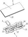
图1是本实用新型所述盖板与LED显示模组的连接结构分解图一;1 is an exploded
图2是本实用新型所述盖板和LED显示模组的连接结构分解图二;Fig. 2 is the second exploded view of the connection structure of the cover plate and the LED display module of the present invention;
图3是本实用新型所述盖板和LED显示模组的连接结构分解图三;3 is an exploded view of the connection structure of the cover plate and the LED display module according to the present invention;
图4是本实用新型所述盖板和LED显示模组的组合图;4 is a combined view of the cover plate and the LED display module of the present invention;
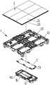
图5是本实用新型所述箱体固定架的结构分解图一;Fig. 5 is the structural exploded
图6是本实用新型所述箱体固定架的结构分解图二;Fig. 6 is the structural exploded view two of the box body fixing frame of the present utility model;
图7是本实用新型所述盖板、LED显示模组和箱体固定架的组合图一;Fig. 7 is a combination diagram 1 of the cover plate, the LED display module and the box body fixing frame according to the present invention;
图8是本实用新型所述盖板、LED显示模组和箱体固定架的组合图二。FIG. 8 is a combined view of the cover plate, the LED display module and the box body fixing frame according to the present invention.
具体实施方式Detailed ways
下面结合附图和具体实施例对本实用新型作进一步详述。The present utility model will be described in further detail below in conjunction with the accompanying drawings and specific embodiments.
本实用新型所揭示的是一种LED显示模组盖板,如图1-4所示,为本实用新型的较佳实施例。所述的盖板1可拆卸地安装在LED显示模组2背面,具体的,两者可通过螺丝锁附。The utility model discloses an LED display module cover plate, as shown in Figs. 1-4, which is a preferred embodiment of the utility model. The
所述的盖板1相对LED显示模组2一面设有容纳槽11,该容纳槽11槽口两侧边可设有平板12;而该盖板1远离LED显示模组2的另一面即背面由于容纳槽11的存在而形成凸起结构15,该凸起结构15可以直接作为把手位。所述容纳槽11可以为两端宽中间窄的结构,相应的,该凸起结构15也为两端宽中间窄的结构,其中间窄处形成凹陷结构16,该凹陷结构16作为把手位时更有利于手指抓取;该凹陷结构16处更可穿透平板12形成让位孔17,以避让手指方便抓取。该把手位的设置,可方便连接在盖板1上的LED显示模组2的拿取,也方便LED显示模组的拆装与维护。The
所述的LED显示模组2包括LED灯板21及底壳22,该LED灯板21及底壳22两者之间具体可以通过螺丝进行螺纹连接,以方便拆卸。所述的盖板1也可以通过螺丝锁附于所述底壳22上,具体的,可以通过在所述的平板12上设置通孔以便螺丝穿过而锁附在底壳22上。The
上述固定有盖板1的LED显示模组2,在LED显示屏安装时,直接将LED显示模组2连同盖板1一起安装在箱体固定架5上,如图5-8所示。而在显示屏安装过程中还要考虑数据信号线的连接,为避免信号线的混乱,本实用新型采用如下连接结构:The above
该连接结构包括一块转接板3,该转接板3上设有第一信号接口31及转接接口32,该转接接口32通过数据线与LED灯板21上的接口连接。该转接板3固定安装在所述盖板1的容纳槽11内,具体的,可以通过螺丝锁固在容纳槽11的一端宽槽内,而该容纳槽11对应第一信号接口31的位置设有开口13,以便第一信号接口31可以从盖板1背面露出。所述容纳槽11的两端也设有用于连接线穿过的开放端口14,方便连接线连接。The connection structure includes an
所述箱体固定架5的背面还设有电源盒6和HUB板7,用于控制LED显示模组2的工作和提供电能;所述电源盒6与箱体固定架5进行可拆卸连接,电源8设于电源盒6内,该电源盒6两侧设有电源接口61以连接电源线;所述HUB板7固定连接于箱体固定架5的背面且电源盒6覆盖于该HUB板7上,则相当于HUB板7被电源盒6保护于其内,为方便接通控制器。所述HUB板7上设有若干第二信号接口71,该HUB板7装设于箱体固定架5上时,各个第二信号接口71的位置与转接板3的第一信号接口31相对应,组装时第一信号接口31与第二信号接口71相互插接实现信号的连接。The back of the box
另外,所述的箱体固定架5上设有与LED显示模组2形状相配合的空心槽51,根据所需的显示屏大小,箱体固定架5可设有多个空心槽51以安装多个LID显示模组2。安装时,抓取所述盖板1的把手位(即凸起结构15或者凹陷结构16),连同LED显示模组2一起装设入空心槽51内,并可以通过螺纹连接。此外,也可以通过磁铁吸附方式进行固定安装。具体是,在所述空心槽51周侧的框架上设置若干磁铁52,所述底壳22相应位置也设置若干相配合的磁钉23,磁铁52和磁钉23均可以通过螺钉锁附在箱体固定架5或底壳22上;这样,就可以通过磁吸附将LED显示模组2装设于箱体固定架5上。而以上两种连接方式也可同时使用,使连接更加稳定。In addition, the box
以上所述,仅是本实用新型的较佳实施例而已,并非对本实用新型的技术范围作任何限制,故但凡依本实用新型的权利要求和说明书所做的变化或修饰,皆应属于本实用新型专利涵盖的范围之内。The above are only preferred embodiments of the present utility model, and do not limit the technical scope of the present utility model. Therefore, any changes or modifications made according to the claims and description of the present utility model shall belong to the present utility model. covered by the new patent.
Claims (8)
Priority Applications (1)
| Application Number | Priority Date | Filing Date | Title |
|---|---|---|---|
| CN202120728255.5UCN216435357U (en) | 2021-04-09 | 2021-04-09 | LED display module group cover plate and LED display module group connecting structure |
Applications Claiming Priority (1)
| Application Number | Priority Date | Filing Date | Title |
|---|---|---|---|
| CN202120728255.5UCN216435357U (en) | 2021-04-09 | 2021-04-09 | LED display module group cover plate and LED display module group connecting structure |
Publications (1)
| Publication Number | Publication Date |
|---|---|
| CN216435357Utrue CN216435357U (en) | 2022-05-03 |
Family
ID=81314781
Family Applications (1)
| Application Number | Title | Priority Date | Filing Date |
|---|---|---|---|
| CN202120728255.5UActiveCN216435357U (en) | 2021-04-09 | 2021-04-09 | LED display module group cover plate and LED display module group connecting structure |
Country Status (1)
| Country | Link |
|---|---|
| CN (1) | CN216435357U (en) |
- 2021
- 2021-04-09CNCN202120728255.5Upatent/CN216435357U/enactiveActive
Similar Documents
| Publication | Publication Date | Title |
|---|---|---|
| US11375625B2 (en) | Electronic apparatus | |
| US20130175993A1 (en) | Tablet storage and charging cart | |
| US6614979B2 (en) | Chassis for fiber optic communication equipment | |
| CN216435357U (en) | LED display module group cover plate and LED display module group connecting structure | |
| US10255786B2 (en) | Server computing device lighting for maintenance | |
| CN210606402U (en) | Display screen module unit and LED display screen with same | |
| CN103064465A (en) | Notebook computer with detachable camera | |
| CN214586828U (en) | Track ball mouse | |
| CN212968604U (en) | Floor integrated direct-current power supply system | |
| CN216161367U (en) | Box body assembly of LED display device and LED display device | |
| KR102399609B1 (en) | LED Display Unit with easy installation | |
| CN208689481U (en) | A kind of docking station | |
| CN210804475U (en) | Face recognition machine and gate | |
| CN210442763U (en) | Seat management system compatible with content production | |
| CN209130584U (en) | An easy-to-install ambient light | |
| CN208672864U (en) | A kind of intelligent maintenance device and its optical port locator of computer room fibre distribution frame | |
| CN223155153U (en) | A fast lighting FPC inspection device | |
| CN207427374U (en) | A kind of front and rear dismounting distributing frame | |
| CN214542853U (en) | Data line shell that protecting effect is good | |
| CN222262925U (en) | Industrial grade switch | |
| CN215494783U (en) | Light and thin portable display | |
| CN219916276U (en) | Cloud computer Main machine box | |
| CN213846755U (en) | A mobile phone shooting auxiliary bracket | |
| KR102399610B1 (en) | LED Display Unit | |
| CN213584327U (en) | USB interface socket power supply convenient to plug |
Legal Events
| Date | Code | Title | Description |
|---|---|---|---|
| GR01 | Patent grant | ||
| GR01 | Patent grant | ||
| CP03 | Change of name, title or address | Address after:No. 5-5 Yutaishi Road, Torch High tech Zone (Xiang'an) Industrial Zone, Xiamen City, Fujian Province 361000 Patentee after:FUJIAN QIANGLI PHOTOELECTRICITY Co.,Ltd. Country or region after:China Address before:361000 No. 8065, building E6, Xiang'an West Road, Xiamen Torch High tech Zone (Xiang'an) Industrial Zone, Xiamen, Fujian Patentee before:FUJIAN QIANGLI PHOTOELECTRICITY Co.,Ltd. Country or region before:China | |
| CP03 | Change of name, title or address |