CN216288947U - Array antenna based on ridge gap waveguide - Google Patents
Array antenna based on ridge gap waveguideDownload PDFInfo
- Publication number
- CN216288947U CN216288947UCN202123220679.XUCN202123220679UCN216288947UCN 216288947 UCN216288947 UCN 216288947UCN 202123220679 UCN202123220679 UCN 202123220679UCN 216288947 UCN216288947 UCN 216288947U
- Authority
- CN
- China
- Prior art keywords
- ridge
- conductive
- conductive plate
- array antenna
- gap
- Prior art date
- Legal status (The legal status is an assumption and is not a legal conclusion. Google has not performed a legal analysis and makes no representation as to the accuracy of the status listed.)
- Active
Links
Images


Landscapes
- Waveguide Aerials (AREA)
Abstract
Description
Translated fromChinese技术领域technical field
本实用新型涉及天线技术领域,具体涉及一种基于脊间隙波导的阵列天线。The utility model relates to the technical field of antennas, in particular to an array antenna based on a ridge-gap waveguide.
背景技术Background technique
为保证轨道列车的正常安全运行,轨道列车与地面控制中心需进行实时信息交换。目前,车地通信的信息交互的方式主要存在三种:微波毫米波通信、LCX(Leaky CoaxialCable,即泄漏同轴电缆)和轨间电缆。其中,微波毫米波通信具有造价低、技术较为成熟、安装便利等优点,是一种主流的车地通信方式。In order to ensure the normal and safe operation of the rail train, the rail train and the ground control center need to exchange real-time information. At present, there are mainly three ways of information exchange in vehicle-ground communication: microwave and millimeter wave communication, LCX (Leaky Coaxial Cable, namely leaky coaxial cable) and inter-rail cable. Among them, microwave and millimeter-wave communication has the advantages of low cost, relatively mature technology, and convenient installation, and is a mainstream vehicle-to-ground communication method.
一种常见的毫米波天线包括喇叭天线、介质透镜和圆极化赋形反射板,喇叭天线的矩圆过渡段直接与BJ320矩形波导相连,喇叭天线产生一个线极化的较宽辐射波束,经介质透镜聚束之后,形成一个相对较窄的波束,这个线极化窄波束经倾斜45°放置的圆极化反射板反射之后,形成圆极化水平波束反射出去。A common millimeter-wave antenna includes a horn antenna, a dielectric lens and a circularly polarized shaped reflector. The rectangular transition section of the horn antenna is directly connected to the BJ320 rectangular waveguide. After the dielectric lens is focused, a relatively narrow beam is formed. This linearly polarized narrow beam is reflected by a circularly polarized reflector placed at an angle of 45° to form a circularly polarized horizontal beam that is reflected out.
这种基于反射面天线的天线形式能够一定程度上满足通信要求,但存在的主要不足是天线体积较大、高度很高,容易增加轨道列车的运行阻力。This kind of antenna based on the reflector antenna can meet the communication requirements to a certain extent, but the main disadvantage is that the antenna is large in size and high in height, which is easy to increase the running resistance of the rail train.
实用新型内容Utility model content
本实用新型的目的是提供一种基于脊间隙波导的阵列天线,其体积相对较小,并能够使得两缝隙线阵辐射相位保持一致。The purpose of the present invention is to provide an array antenna based on a ridge-gap waveguide, which has a relatively small volume and can keep the radiation phases of the two slot linear arrays consistent.
为解决上述技术问题,本实用新型提供一种基于脊间隙波导的阵列天线,包括相对设置的第一导电板和第二导电板,所述第一导电板设置有导电脊和若干导电杆,各所述导电杆围绕所述导电脊设置,所述导电脊和各所述导电杆均与所述第二导电板间隙配合,所述第二导电板设置有两列相平行的缝隙线阵,各所述缝隙线阵均包括若干带有耦合枝节的通孔,两列所述缝隙线阵之间具有中心线;所述导电脊包括入口脊段和相对设置的两个馈电网络模块,所述入口脊段与两所述馈电网络模块均相连,两所述馈电网络模块均包括若干馈电脊段,两所述馈电网络模块与两所述缝隙线阵一一对应,所述馈电网络模块的各所述馈电脊段与相对应的所述缝隙线阵的各所述通孔一一对应耦合,所述入口脊段与所述中心线相平行,且所述入口脊段与所述中心线的间距L与待传输电磁波的波长λ之间满足如下关系:L=(n+1/4)λ,其中,n为自然数。In order to solve the above technical problems, the present invention provides an array antenna based on a ridge-gap waveguide, comprising a first conductive plate and a second conductive plate arranged opposite to each other, the first conductive plate is provided with a conductive ridge and a plurality of conductive rods, each of which is provided with a conductive ridge. The conductive rods are arranged around the conductive ridges, and the conductive ridges and each of the conductive rods are gap-fitted with the second conductive plate, and the second conductive plate is provided with two rows of parallel slot line arrays, each Each of the slot line arrays includes a plurality of through holes with coupling branches, and a center line is arranged between two rows of the slot line arrays; the conductive ridge includes an inlet ridge segment and two oppositely arranged feeding network modules. The inlet ridge segment is connected to both of the feed network modules, both of the feed network modules include a plurality of feed ridge segments, and the two feed network modules are in one-to-one correspondence with the two slot line arrays. Each of the feeding ridge segments of the electrical network module is coupled to each of the through holes of the corresponding slot line array in a one-to-one correspondence, the inlet ridge segment is parallel to the center line, and the inlet ridge segment is parallel to the center line. The following relationship is satisfied between the distance L from the center line and the wavelength λ of the electromagnetic wave to be transmitted: L=(n+1/4)λ, where n is a natural number.
区别于现有技术,本实用新型所提供阵列天线利用脊间隙波导实现电磁波信号的传播,且作为信号发射端的第二导电板所设置缝隙线阵包括带有耦合枝节的通孔,可形成圆极化的辐射单元,无需额外的极化转换装置,有利于缩减天线的体积,以方便安装,并能够减少因配置天线而导致的轨道车辆运行阻力的增加。Different from the prior art, the array antenna provided by the present invention utilizes a ridge-gap waveguide to realize the propagation of electromagnetic wave signals, and the slot line array set on the second conductive plate as the signal transmitting end includes through holes with coupling branches, which can form circular poles. The optimized radiation unit does not require an additional polarization conversion device, which is beneficial to reduce the volume of the antenna to facilitate installation, and can reduce the increase in the running resistance of the rail vehicle caused by the configuration of the antenna.
另外,本实用新型将入口脊段与中心线设置为间隙设置,并具体地将入口脊段与中心线的间距L控制为(n+1/4)λ,可以弥补两缝隙线阵的相位差,使得两缝隙线阵辐射相位保持一致,如此,两缝隙线阵同相叠加后可形成最终的天线圆极化辐射。In addition, the utility model sets the entrance ridge segment and the center line as a gap setting, and specifically controls the distance L between the entrance ridge segment and the center line to be (n+1/4)λ, which can compensate for the phase difference between the two slot linear arrays. , so that the radiation phases of the two slot linear arrays are consistent, so that the final circularly polarized radiation of the antenna can be formed after the two slot linear arrays are superimposed in phase.
可选地,所述导电脊还包括功分段,所述功分段包括输入端部和两个输出端部,所述输入端部和两个输出端部均相连,所述入口脊段通过所述功分段与两所述馈电网络模块相连,且两所述馈电网络模块均包括至少一个所述功分段。Optionally, the conductive ridge further includes a work segment, and the work segment includes an input end and two output ends, the input end and the two output ends are both connected, and the inlet ridge segment passes through. The power segment is connected to two of the feeder network modules, and both of the feeder network modules include at least one of the power segment.
可选地,两所述输出端部相连接,且两所述输出端部在同一方向延伸,两所述输出端部的连接处在背离所述输入端部的一侧设置有缺口,所述输入端部包括细颈部和粗颈部,所述输入端部通过所述粗颈部与两所述输出端部相连。Optionally, the two output ends are connected, and the two output ends extend in the same direction, and a gap is provided on the side away from the input end at the connection of the two output ends, and the The input end portion includes a thin neck portion and a thick neck portion, and the input end portion is connected with the two output end portions through the thick neck portion.
可选地,所述导电脊包括若干拐角段,所述拐角段的外端侧设置有切口。Optionally, the conductive ridge includes several corner segments, and the outer end sides of the corner segments are provided with cutouts.
可选地,各所述馈电网络模块均包括十六个所述馈电脊段。Optionally, each of the feed network modules includes sixteen of the feed ridge segments.
可选地,所述入口脊段包括若干分部,沿所述待传输电磁波的传输方向,各所述分部与所述第二导电板的间隙逐级缩小,相邻两所述分部之间形成台阶面。Optionally, the inlet ridge section includes a plurality of subsections, and along the transmission direction of the electromagnetic wave to be transmitted, the gap between each subsection and the second conductive plate is gradually reduced, and the gap between the two adjacent subsections is gradually reduced. Form a step surface.
可选地,所述第一导电板设置有与外部的传输波导相连的开孔,所述入口脊段的端壁与所述开孔的孔壁相对齐,所述开孔的外周也设置有所述导电杆。Optionally, the first conductive plate is provided with an opening connected to an external transmission waveguide, the end wall of the inlet ridge section is aligned with the hole wall of the opening, and the outer periphery of the opening is also provided with a hole. the conductive rod.
可选地,所述馈电脊段呈L型,包括相连接的横部和竖部,所述横部远离所述竖部的端面与所述耦合枝节的延伸方向呈3.5度-4.5度的夹角。Optionally, the feeding ridge segment is L-shaped, and includes a horizontal part and a vertical part that are connected, and the end face of the horizontal part far from the vertical part is 3.5 degrees to 4.5 degrees from the extension direction of the coupling branch. angle.
可选地,所述第二导电板包括薄板区域,两所述缝隙线阵均布置于所述薄板区域。Optionally, the second conductive plate includes a thin plate area, and both the slot line arrays are arranged in the thin plate area.
可选地,所述第一导电板、所述第二导电板、所述导电脊和所述导电杆的材质均为铝。Optionally, the first conductive plate, the second conductive plate, the conductive ridge and the conductive rod are all made of aluminum.
附图说明Description of drawings
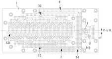
图1为本实用新型所提供基于脊间隙波导的阵列天线的一种具体实施方式的结构示意图;1 is a schematic structural diagram of a specific embodiment of an array antenna based on a ridge gap waveguide provided by the present invention;
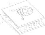
图2为图1的爆炸图;Fig. 2 is the exploded view of Fig. 1;
图3为第一导电板及安装于第一导电板的导电脊和导电杆的俯视图;3 is a top view of the first conductive plate and the conductive ridges and conductive rods mounted on the first conductive plate;
图4为功分段的结构示意图;Fig. 4 is the structural representation of work segment;
图5为入口脊段的结构示意图;Fig. 5 is the structural representation of inlet ridge section;
图6为带有耦合枝节的通孔的结构示意图;6 is a schematic structural diagram of a through hole with a coupling branch;
图7为图6的俯视图;Fig. 7 is the top view of Fig. 6;
图8为本实用新型所提供阵列天线的天线驻波图;8 is an antenna standing wave diagram of an array antenna provided by the utility model;
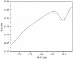
图9为本实用新型所提供阵列天线主射方向上轴比随频率的变化图;Fig. 9 is the variation diagram of the axial ratio with frequency in the main radiation direction of the array antenna provided by the utility model;
图10为本实用新型所提供阵列天线主射方向上增益随频率的变化图;10 is a graph of the variation of gain with frequency in the main radiation direction of the array antenna provided by the utility model;
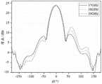
图11为本实用新型所提供阵列天线在俯仰面辐射方向图;11 is a radiation pattern of the array antenna provided by the utility model in the elevation plane;
图12为本实用新型所提供阵列天线在方位面辐射方向图。FIG. 12 is a radiation pattern of the array antenna provided by the utility model in the azimuth plane.
图1-图7中的附图标记说明如下:The reference numerals in Figures 1-7 are explained as follows:
1第一导电板、11开孔;1 The first conductive plate, 11 opening;
2第二导电板、21缝隙线阵、211通孔、212耦合枝节、2a薄板区域、2b厚板区域;2 second conductive plate, 21 slot line array, 211 through hole, 212 coupling branch, 2a thin plate area, 2b thick plate area;
3导电脊、31入口脊段、311第一分部、312第二分部、313第三分部、32馈电网络模块、321馈电脊段、321a横部、321b竖部、33功分段、331输入端部、331a细颈部、331b粗颈部、332输出端部、333缺口、34拐角段、341切口;3 Conductive Ridge, 31 Inlet Ridge Section, 311 First Section, 312 Second Section, 313 Third Section, 32 Feed Network Module, 321 Feed Ridge Section, 321a Horizontal Section, 321b Vertical Section, 33 Power Section segment, 331 input end, 331a thin neck, 331b thick neck, 332 output end, 333 notch, 34 corner segment, 341 cut;
4导电杆4 conductive rods
具体实施方式Detailed ways
为了使本领域的技术人员更好地理解本实用新型的技术方案,下面结合附图和具体实施例对本实用新型作进一步的详细说明。In order to make those skilled in the art better understand the technical solutions of the present invention, the present invention will be further described in detail below with reference to the accompanying drawings and specific embodiments.
本文中所述“若干”是指数量不确定的多个,通常为两个以上;且当采用“若干”表示某几个部件的数量时,并不表示这些部件在数量上的相互关系。The "several" mentioned herein refers to an indefinite number, usually two or more; and when the "several" is used to indicate the number of certain components, it does not indicate the quantitative relationship of these components.
本文中所述“第一”、“第二”等词,仅是为了便于描述结构和/或功能相同或者相类似的两个以上的结构或者部件,并不表示对于顺序和/或重要性的某种特殊限定。The terms "first" and "second" mentioned in this document are only for the convenience of describing two or more structures or components with the same or similar structures and/or functions, and do not indicate any order and/or importance. some kind of special restriction.
请参考图1-图7,图1为本实用新型所提供基于脊间隙波导的阵列天线的一种具体实施方式的结构示意图,图2为图1的爆炸图,图3为第一导电板及安装于第一导电板的导电脊和导电杆的俯视图,图4为功分段的结构示意图,图5为入口脊段的结构示意图,图6为带有耦合枝节的通孔的结构示意图,图7为图6的俯视图。Please refer to FIGS. 1-7 , FIG. 1 is a schematic structural diagram of a specific implementation manner of an array antenna based on a ridge gap waveguide provided by the present invention, FIG. 2 is an exploded view of FIG. 1 , and FIG. 3 is a first conductive plate and The top view of the conductive ridges and the conductive rods installed on the first conductive plate, FIG. 4 is a schematic structural diagram of the power segment, FIG. 5 is a structural schematic diagram of the inlet ridge section, and FIG. 6 is a structural schematic diagram of a through hole with a coupling branch, FIG. 7 is a top view of FIG. 6 .
如图1-图3所示,本实用新型提供一种基于脊间隙波导的阵列天线,包括相对设置的第一导电板1和第二导电板2,第一导电板1设置有导电脊3和若干导电杆4。在装配状态下,第一导电板1和第二导电板2可以通过螺钉、螺栓等形式的连接件进行连接,并保持一定的间距,使得导电脊3可以与第二导电板2形成间隙配合,进而可以在导电脊3和第二导电板2之间形成脊间隙波导,用于传输电磁波信号;该电磁波信号的波长、频率等参数信息在此不做限定,当应用车地通信领域时,该电磁波信号通常可以为Ka波段。各导电杆4可以围绕导电脊3设置,且各导电杆4与第二导电板2也可以间隙配合,基于各导电杆4的禁带特性,使得电磁波信号只能沿着导电脊3的延伸方向进行传播,从而可以确保电磁波信号按照导电脊3的延伸方向进行传播。As shown in FIG. 1-FIG. 3, the present invention provides an array antenna based on ridge-gap waveguide, which includes a first
第二导电板2可以设置有两列相平行的缝隙线阵21,以形成信号发射端,各缝隙线阵21均包括若干带有耦合枝节212的通孔211,两列缝隙线阵21之间具有中心线。The second
两导电板以及导电脊3、导电杆4的尺寸可以不做限定,具体实践中,本领域技术人员可以根据实际需要进行设置。作为一种示例性的说明,第二导电板2的厚度可以为1mm,长度可以为138mm,宽度可以为65mm;导电脊3的宽度可以为1.3mm,高度可以为2mm,导电脊3与第二金属板2之间的空气间隙的高度可以为0.35mm;导电脊3在宽度方向上和相邻的导电杆4的间距可以为1.9mm;导电杆4的截面可以为正方形,其长度和宽度均可以为0.7mm,高度也可以为2mm,相邻两导电杆4的间距可以为1.9mm;第一导电板1的厚度可以为2mm,长度可以为138mm,宽度可以为65mm。The sizes of the two conductive plates, the
导电脊3包括入口脊段31和相对设置的两个馈电网络模块32,入口脊段31与两馈电网络模块32均相连,用于向两个馈电网络模块32分配电磁波能量。两馈电网络模块32均包括若干馈电脊段321,两馈电网络模块32与两缝隙线阵21一一对应,馈电网络模块32的各馈电脊段321与相对应的缝隙线阵21的各通孔211一一对应耦合。也就是说,馈电脊段321和通孔211的数量可以一致,且安装位置可以一一对应。The
实际上,馈电脊段321和通孔211的数量决定了电磁波能量的分配方式,假定各馈电网络模块32均包括M个馈电脊段321,那么,电磁波能量可以按照1分2M的方式进行分配。在附图实施例中,如图3所示,各馈电网络模块32均包括十六个馈电脊段321,那么,电磁波能量可以按照一分三十二的方式进行分配。In fact, the number of feeding
进一步地,入口脊段31可以与中心线相平行,且入口脊段31与中心线的间距L与待传输电磁波的波长λ之间满足如下关系:L=(n+1/4)λ,其中,n为自然数。Further, the
区别于现有技术,本实用新型实施例所提供阵列天线利用脊间隙波导实现电磁波信号的传播,且作为信号发射端的第二导电板2所设置缝隙线阵21包括带有耦合枝节212的通孔211,可形成圆极化的辐射单元,无需额外的极化转换装置,有利于缩减天线的体积,以方便安装,并能够减少因配置天线而导致的轨道车辆运行阻力的增加。Different from the prior art, the array antenna provided by the embodiment of the present invention uses a ridge-gap waveguide to realize the propagation of electromagnetic wave signals, and the
另外,由于导电脊3包括相对设置的两个馈电网络模块32,电磁波信号在两馈电网络模块32的馈电脊段321与相应的通孔211处进行耦合辐射时,两缝隙线阵21辐射相位相差180度。对此,在本实用新型实施例中,可以将入口脊段31与中心线设置为间隙设置,并具体地将入口脊段31与中心线的间距L控制为(n+1/4)λ,进而可以弥补两缝隙线阵21的相位差,使得两缝隙线阵21辐射相位保持一致,如此,两缝隙线阵21同相叠加后可形成最终的天线圆极化辐射。In addition, since the
如图4所示,导电脊3还可以包括功分段33,用于实现电磁波能量的功率分配,该功分段33可以包括输入端部331和两个输出端部332,输入端部331和两个输出端部332均可以相连。一并结合图3,入口脊段31可以通过功分段33与两馈电网络模块32相连,这样,电磁波能量可以一分为二分配给两个馈电网络模块32。As shown in FIG. 4 , the
详细而言,两输出端部332可以相连接,且两输出端部332可以在同一方向延伸,两输出端部332的连接处在背离输入端部331的一侧可以设置有缺口333,输入端部331可以包括细颈部331a和粗颈部331b,输入端部331可以通过粗颈部331b与两输出端部332相连,用于实现功分段33的阻抗匹配。In detail, the two output ends 332 can be connected, and the two output ends 332 can extend in the same direction, and the connection of the two output ends 332 can be provided with a
实际上,两馈电网络模块32均可以包括有功分段33,以实现电磁波能量在各馈电网络模块32中的功率分配,所设置功分段33的数量不同,最终所能够形成的馈电脊段321的数量也会存在差异。这里,本实用新型实施例仅以图3中所示出的结构对馈电网络模块32的结构进行说明。In fact, both
为便于描述,可以将直接与馈电脊段321相连的功分段33称之为第一级功分段,如图所示,单个馈电网络模块32可以包括八个第一级功分段,进而可以形成十六个馈电脊段321;八个第一级功分段中,相邻的两个第一级功分段的上游可以连接一个第二级功分段,这样,就存在四个第二级功分段;四个第二级功分段中,相邻两个第二级功分段的上游可以连接一个第三级功分段,这样,就存在两个第三级功分段;两个第三级功分段的上游连接有一个第四级功分段;两个馈电网络模块32可以存在两个第四级功分段,两个第四级功分段的上游可以连接一个第五级功分段,第五级功分段的输入端部331可以和入口脊段31相连。For ease of description, the
如此设置,即可以形成一分三十二的馈电网络;且各级功分段均是采用中心馈电的方式进行传输,使得各缝隙线阵21中的每一个通孔211均能够产生等幅同相激励,避免了侧馈系统中当工作频率偏离中心频点时,波束指向发生偏转、轴向增益下降等问题,可实现毫米波车地通信阵列天线所需的扇形波束和宽频带(36.6GHz-39.5GHz)特性。In this way, a feed network of one point and thirty-two can be formed; and the power segments at all levels are transmitted by means of central feeding, so that each through
为便于导电脊3在第一导电板1的布置,导电脊3可以包括若干拐角段34,以在第一导电板1上形成若干次的转弯设计,拐角段34的外端侧可以设置有切口341。In order to facilitate the arrangement of the
在本实用新型实施例中,并不对导电脊3的具体尺寸做限定,具体实践中,本领域技术人员可以根据实际需要进行配置。作为一种示例性的说明,大致呈L型的馈电脊段321的横部321a的长度可以为1.65mm,竖部321b的长度可以为3.8mm,横部321a和竖部321b所形成拐角段34的切口341的长度可以为0.8mm;第一级公分段的两个输出端部332的长度相等,均可以为2.85mm,输入端部331的长度可以为3.8mm,输入端部331与上游功分段连接处所形成拐角段34的切口341的长度可以为0.9mm,两输出端部332之间的缺口333大致为三角形,该三角形的高可以为0.8mm,底可以为3.6mm,粗颈部331b的长度可以为1.9mm,宽度可以为1.7mm;第二级公分段的两个输出端部332的长度相等,均可以为5.7mm,输入端部331的长度可以为4.3mm,输入端部331与上游功分段连接处所形成拐角段34的切口341的长度可以为1.8mm,两输出端部332之间的缺口333大致为三角形,该三角形的高可以为0.8mm,底可以为4.1mm,粗颈部331b的长度为2.5mm,宽度为1.9mm;第三级公分段的两个输出端部332的长度相等,均可以为11.4mm,输入端部331的长度为4.3mm,输入端部331与上游功分段连接处所形成拐角段34的切口341的长度可以为1.55mm,两输出端部332之间的缺口333大致为三角形,该三角形的高可以为0.9mm,底可以为5.2mm,粗颈部331b的长度可以为2.5mm,宽度可以为2.1mm;第四级公分段的两个输出端部332的长度相等,均可以为22.8mm,输入端部331的长度为5.7mm,输入端部331与上游段连接处所形成拐角段34的切口341的长度可以为1.65mm,两输出端部332之间的缺口333大致为三角形,该三角形的高可以为0.9mm,底可以为4.8mm,粗颈部331b的长度可以为2.4mm,宽度可以为2.1mm;第五级公分段的两个输出端部332的长度不等,分别为29.85mm和25.24mm,输入端部331的长度可以为12.35mm,两输出端部332之间的缺口333大致为三角形,该三角形的高可以为0.9mm,底可以为5mm,粗颈部331b的长度可以为2.5mm,宽度可以为2.1mm。In the embodiment of the present invention, the specific size of the
进一步地,如图5所示,入口脊段31可以包括若干分部,沿待传输电磁波的传输方向,各分部与第二导电板2的间隙可以逐级缩小,相邻两分部之间形成台阶面(图中未标注),使得电磁波可以逐步耦合至导电脊3,并使得电磁波沿导电脊进行传播。Further, as shown in FIG. 5 , the
在附图的实施例中,入口脊段31可以包括三个分部,沿电磁波的传输方向,这三个分部可以分别称之为第一分部311、第二分部312和第三分部313。当然,在具体实践中,也可以设置其他数量的分部,只要能够实现上述的效果即可。In the embodiment of the drawings, the
第一导电板1还可以设置有与外部的传输波导相连的开孔11,入口脊段31的端壁可以与开孔11的孔壁相对齐,开孔11的外周也可以设置有导电杆4。这样,在电磁波信号自外部的传输波导进入本实用新型所提供阵列天线后,可以直接沿着导电脊3进行传播,不易造成电磁波能量的逸散。The first
结合图6和图7,馈电脊段321可以呈L型,包括相连接的横部321a和竖部321b,横部321a远离竖部321b的端面与耦合枝节212的延伸方向可以呈3.5度-4.5度的夹角θ,用于提高辐射性能。6 and 7, the
第二导电板2可以包括薄板区域2a,两缝隙线阵21均可以布置于薄板区域2a。缝隙阵列21中的各通孔211具体可以是通过刻蚀工艺形成,在薄板区域2a对缝隙线阵21进行加工时,可以降低加工的难度。薄板区域2a外的其他区域的厚度相比于薄板区域2a可以增加,在本实用新型实施例中,可以将这部分的区域称之为厚板区域2b,用于满足第二导电板2的结构强度需求。The second
这里,本实用新型实施例也不对通孔211的结构尺寸进行限定,在具体实践中,本领域技术人员可以根据实际需要进行确定,只要能够满足使用的要求即可。作为一种示例性的说明,请结合图7,通孔211的外径可以为2.7mm,内径可以为0.95mm,耦合枝节212的宽度可以为0.5m。在实际应用中,可以通过合理地搭配馈电脊段321和通孔211的尺寸,使得天线可以实现良好的圆极化性能和驻波。Here, the embodiment of the present invention also does not limit the structure size of the through
上述的第一导电板1、第二导电板2、导电脊3和导电杆4的材质可以多种多样,只要能够满足使用的要求即可。具体到本实用新型实施例中,上述各部分的材质可以优选为铝,以方便加工。The above-mentioned materials of the first
请参考图8-图12,图8为本实用新型所提供阵列天线的天线驻波图,图9为本实用新型所提供阵列天线主射方向上轴比随频率的变化图,图10为本实用新型所提供阵列天线主射方向上增益随频率的变化图,图11为本实用新型所提供阵列天线在俯仰面辐射方向图,图12为本实用新型所提供阵列天线在方位面辐射方向图。Please refer to FIGS. 8-12 , FIG. 8 is the antenna standing wave diagram of the array antenna provided by the present invention, FIG. 9 is the change diagram of the axial ratio with the frequency in the main radiation direction of the array antenna provided by the present invention, and FIG. Figure 11 is the radiation pattern of the array antenna provided by the utility model in the elevation plane, and Figure 12 is the radiation pattern of the array antenna provided by the utility model in the azimuth plane. .
针对本实用新型所提供的具有一种具体尺寸的阵列天线进行测试:如图8-图10所示,该阵列天线在36.6GHz-39.4GHz频带内驻波比小于1.4,主射方向轴比小于3dB,增益大于23.5dBi;如图11所示,其波束宽度约为4.2°;如图11所示,其波束宽度约为35°。经测试,本实用新型所提供阵列天线在上述频带内,具有良好驻波比、轴比、增益和波束宽度,证明了其运用于毫米波车地通信的可行性。The array antenna with a specific size provided by the utility model is tested: as shown in Figures 8-10, the standing wave ratio of the array antenna in the 36.6GHz-39.4GHz frequency band is less than 1.4, and the axial ratio of the main radiation direction is less than 3dB, the gain is greater than 23.5dBi; as shown in Figure 11, its beam width is about 4.2°; as shown in Figure 11, its beam width is about 35°. After testing, the array antenna provided by the utility model has good standing wave ratio, axial ratio, gain and beam width in the above-mentioned frequency band, which proves the feasibility of applying it to millimeter wave vehicle-ground communication.
需要强调的是,尽管本实用新型所提供阵列天线的设计初衷是针对于轨道列车的车地通信,但显然,本实用新型所提供阵列天线的应用范围并不局限于轨道列车领域,也就是说,应用领域实际上并不能够构成对本实用新型所提供阵列天线的实施范围的限定,其还可以应用于其他的领域中,如坦克等军事设备与指挥中心的通信等、航空器与遥控器的通信等。It should be emphasized that although the original design of the array antenna provided by the present invention is aimed at the train-ground communication of rail trains, obviously, the application range of the array antenna provided by the present invention is not limited to the field of rail trains, that is to say , the application field does not actually constitute a limitation on the implementation scope of the array antenna provided by the present invention, and it can also be applied in other fields, such as the communication between military equipment such as tanks and the command center, and the communication between aircraft and remote controllers. Wait.
以上仅是本实用新型的优选实施方式,应当指出,对于本技术领域的普通技术人员来说,在不脱离本实用新型原理的前提下,还可以做出若干改进和润饰,这些改进和润饰也应视为本实用新型的保护范围。The above are only the preferred embodiments of the present utility model. It should be pointed out that for those skilled in the art, without departing from the principles of the present utility model, several improvements and modifications can also be made. It should be regarded as the protection scope of the present invention.
Claims (10)
Priority Applications (1)
| Application Number | Priority Date | Filing Date | Title |
|---|---|---|---|
| CN202123220679.XUCN216288947U (en) | 2021-12-20 | 2021-12-20 | Array antenna based on ridge gap waveguide |
Applications Claiming Priority (1)
| Application Number | Priority Date | Filing Date | Title |
|---|---|---|---|
| CN202123220679.XUCN216288947U (en) | 2021-12-20 | 2021-12-20 | Array antenna based on ridge gap waveguide |
Publications (1)
| Publication Number | Publication Date |
|---|---|
| CN216288947Utrue CN216288947U (en) | 2022-04-12 |
Family
ID=81056748
Family Applications (1)
| Application Number | Title | Priority Date | Filing Date |
|---|---|---|---|
| CN202123220679.XUActiveCN216288947U (en) | 2021-12-20 | 2021-12-20 | Array antenna based on ridge gap waveguide |
Country Status (1)
| Country | Link |
|---|---|
| CN (1) | CN216288947U (en) |
Cited By (2)
| Publication number | Priority date | Publication date | Assignee | Title |
|---|---|---|---|---|
| CN114824833A (en)* | 2022-07-01 | 2022-07-29 | 盛纬伦(深圳)通信技术有限公司 | Millimeter wave junction type slotted array antenna based on printed circuit board gap waveguide technology |
| CN115377703A (en)* | 2022-10-21 | 2022-11-22 | 盛纬伦(深圳)通信技术有限公司 | K-waveband multi-layer feed monopulse array antenna |
- 2021
- 2021-12-20CNCN202123220679.XUpatent/CN216288947U/enactiveActive
Cited By (3)
| Publication number | Priority date | Publication date | Assignee | Title |
|---|---|---|---|---|
| CN114824833A (en)* | 2022-07-01 | 2022-07-29 | 盛纬伦(深圳)通信技术有限公司 | Millimeter wave junction type slotted array antenna based on printed circuit board gap waveguide technology |
| CN114824833B (en)* | 2022-07-01 | 2022-09-02 | 盛纬伦(深圳)通信技术有限公司 | Millimeter wave junction type slotted array antenna based on printed circuit board gap waveguide technology |
| CN115377703A (en)* | 2022-10-21 | 2022-11-22 | 盛纬伦(深圳)通信技术有限公司 | K-waveband multi-layer feed monopulse array antenna |
Similar Documents
| Publication | Publication Date | Title |
|---|---|---|
| US7183991B2 (en) | Multiple flared antenna horn with enhanced aperture efficiency | |
| CN107658568B (en) | Dual-frequency dual-polarization common-aperture waveguide horn planar array antenna | |
| CN216288947U (en) | Array antenna based on ridge gap waveguide | |
| CN113644432B (en) | Dual circularly polarized phased array antenna array | |
| CN106887716A (en) | A kind of CTS flat plate array antennas | |
| EP3888185A1 (en) | Dual end-fed broadside leaky-wave antenna | |
| Cao et al. | Multi‐beam SIW leaky‐wave antenna with 2‐D beam scanning capability for millimeter‐wave radar applications | |
| CN107978858A (en) | A kind of directional diagram reconstructable aerial for working in 60GHz frequency ranges | |
| US12009596B2 (en) | Planar monolithic combiner and multiplexer for antenna arrays | |
| CN114583459B (en) | Multi-layer gap waveguide slot array antenna | |
| CN108963438A (en) | Low radar cross section array antenna based on polarization conversion | |
| US7095380B2 (en) | Antenna device | |
| CN107706545B (en) | A CTS Array Antenna System with Wide-Angle Scanning Function | |
| CN109119767A (en) | A kind of Ka frequency range circular polarized antenna | |
| CN111710986A (en) | Broadband Reconfigurable Transmission Array Antenna Based on Polarized Rotating Surface | |
| CN114566795B (en) | Flat-top directional diagram millimeter wave radar antenna and system | |
| CN114156652B (en) | A low sidelobe broadband low cross-polarization planar dipole antenna array | |
| CN112713413B (en) | A helical array antenna | |
| CN114639964A (en) | Foldable feed source system of integrated monopulse measurement and control radar antenna | |
| CN117712715B (en) | Broadband dual-polarized antenna array applied to K-band field intensity generation system | |
| CN108270072A (en) | low profile antenna | |
| CN217281205U (en) | Antenna assembly and vehicle radar | |
| CN116130979A (en) | Low-sidelobe back cavity slot array antenna | |
| CN115173039A (en) | Small-size broadband ridge waveguide antenna | |
| RU142669U1 (en) | ULTRA-BAND WAVE-HORNE RADIATOR |
Legal Events
| Date | Code | Title | Description |
|---|---|---|---|
| GR01 | Patent grant | ||
| GR01 | Patent grant |