CN216282901U - Heat exchanger and air conditioner - Google Patents
Heat exchanger and air conditionerDownload PDFInfo
- Publication number
- CN216282901U CN216282901UCN202122056782.9UCN202122056782UCN216282901UCN 216282901 UCN216282901 UCN 216282901UCN 202122056782 UCN202122056782 UCN 202122056782UCN 216282901 UCN216282901 UCN 216282901U
- Authority
- CN
- China
- Prior art keywords
- heat exchange
- refrigerant
- tube
- exchange tube
- chamber
- Prior art date
- Legal status (The legal status is an assumption and is not a legal conclusion. Google has not performed a legal analysis and makes no representation as to the accuracy of the status listed.)
- Active
Links
Images


Landscapes
- Heat-Exchange Devices With Radiators And Conduit Assemblies (AREA)
Abstract
Translated fromChinese
Description
Translated fromChinese技术领域technical field
本实用新型涉及换热器技术领域,特别是涉及一种换热器及空调器。The utility model relates to the technical field of heat exchangers, in particular to a heat exchanger and an air conditioner.
背景技术Background technique
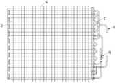
目前空调器大多数采用管翅式换热器,如图1所示,管翅式换热器由换热管2折弯成U管后与翅片6通过机械胀接的方式连接,最后在U管的两端开口焊接有弯管7或分流管组件8而成。现有技术中的U管一般采用管径大于5mm的金属管折弯而成,成形后的U管内部只有一条冷媒通道,冷媒通道的横截面较大,导致了冷媒在冷媒通道内的扰动能力较弱,使得冷媒的热量无法有效传递到U管的管壁,降低了换热效果;同时,冷媒从U管的开口的一侧进行分流,分流方式单一,且U管的折弯部及弯管会使冷媒的分流阻力较大,从而影响换热器的换热效果。At present, most of the air conditioners use tube-fin heat exchangers. As shown in Figure 1, the tube-fin heat exchanger is bent from the
实用新型内容Utility model content
本实用新型的目的是解决了现有的管翅式换热器因冷媒扰动能力较弱且分流阻力较大而存在换热效果较差的技术问题,本实用新型提供了一种换热器,包括:The purpose of the utility model is to solve the technical problem that the existing tube-fin type heat exchanger has poor heat exchange effect due to weak refrigerant disturbance ability and large shunt resistance. The utility model provides a heat exchanger, include:
两个集流管,两个所述集流管相对间隔且平行设置,两个所述集流管之间设有多个依次间隔设置的换热管,各所述换热管的两端分别与两个所述集流管连通,各所述换热管的内部形成有多个冷媒通道;各所述集流管内设有若干个隔板,各所述集流管通过所述隔板隔断成多个腔室,两个所述集流管的所述腔室通过多个所述换热管的冷媒通道顺次连通以形成冷媒流路;所述腔室包括第一腔室和第二腔室,所述第一腔室及所述第二腔室分别设于所述冷媒流路的两端;Two headers, the two headers are spaced apart and parallel to each other, and a plurality of heat exchange tubes arranged at intervals in sequence are arranged between the two headers, and the two ends of each of the heat exchange tubes are respectively Connected with two of the headers, each of the heat exchange pipes is formed with a plurality of refrigerant channels; each of the headers is provided with a number of partitions, and each of the headers is cut off by the partitions into a plurality of chambers, the chambers of the two headers are connected in sequence through the refrigerant passages of the plurality of the heat exchange tubes to form a refrigerant flow path; the chambers include a first chamber and a second chamber a chamber, the first chamber and the second chamber are respectively disposed at both ends of the refrigerant flow path;
进口管,所述进口管与所述第一腔室连通;以及an inlet tube in communication with the first chamber; and
出口管,所述出口管与所述第二腔室连通。an outlet pipe in communication with the second chamber.
基于上述方案,采用多个冷媒通道同时传输冷媒,在确保冷媒流量的情况下通过缩小冷媒通道的横截面面积来增大冷媒流过换热管的扰动,以使冷媒的热量有效传递到换热管的管壁,增大换热面积以提高换热效果。换热管的两端分别采用集流管进行分流,以使换热管可以采用直线形管体,换热管避免了采用弯折部及弯管进行分流,分流阻力变小,提高了冷媒的流动效率,从而提高换热效果。Based on the above scheme, multiple refrigerant channels are used to transmit the refrigerant at the same time, and the cross-sectional area of the refrigerant channel is reduced to increase the disturbance of the refrigerant flowing through the heat exchange tube while ensuring the flow of the refrigerant, so that the heat of the refrigerant can be effectively transferred to the heat exchange tube. The wall of the tube increases the heat exchange area to improve the heat exchange effect. The two ends of the heat exchange tube are divided by the collector tube, so that the heat exchange tube can use a straight tube body. flow efficiency, thereby improving the heat transfer effect.
在一些实施方式中,所述换热管内设有至少一个固定板,所述固定板沿所述换热管的长度方向延伸,所述固定板的相对两侧分别与所述换热管的内侧壁固定连接,所述换热管的内部通过所述固定板隔断形成多个所述冷媒通道。In some embodiments, at least one fixing plate is provided in the heat exchange tube, the fixing plate extends along the length direction of the heat exchange tube, and opposite sides of the fixing plate are respectively connected to the inner side of the heat exchange tube The walls are fixedly connected, and the interior of the heat exchange tube is cut off by the fixed plate to form a plurality of the refrigerant channels.
在一些实施方式中,所述换热管内设有加强板,所述加强板沿所述换热管的长度方向延伸,所述加强板的相对两侧分别与所述换热管的内侧壁固定连接,所述加强板与所述固定板相互交错设置以使所述换热管的横截面呈格栅状。In some embodiments, a reinforcing plate is provided in the heat exchange tube, the reinforcing plate extends along the length direction of the heat exchange tube, and opposite sides of the reinforcing plate are respectively fixed to the inner side wall of the heat exchange tube connected, the reinforcing plate and the fixing plate are arranged in a staggered manner, so that the cross section of the heat exchange tube is in the shape of a grid.
在一些实施方式中,所述换热管、所述固定板及所述加强板为一体成型结构。In some embodiments, the heat exchange tube, the fixing plate and the reinforcing plate are integrally formed.
在一些实施方式中,所述换热管的内侧壁呈光滑状或凸齿状。In some embodiments, the inner sidewall of the heat exchange tube is smooth or convex.
在一些实施方式中,所述换热管为直线形圆管。In some embodiments, the heat exchange tubes are straight round tubes.
在一些实施方式中,还包括多个依次间隔设置的翅片,各所述换热管依次穿过多个所述翅片。In some embodiments, it also includes a plurality of fins arranged at intervals in sequence, and each of the heat exchange tubes passes through the plurality of fins in sequence.
在一些实施方式中,所述换热管通过胀管机与所述翅片实现胀接。In some embodiments, the heat exchange tube is expanded to the fins through a tube expander.
在一些实施方式中,所述第一腔室和所述第二腔室位于同一个所述集流管的两端。In some embodiments, the first chamber and the second chamber are located at two ends of the same header.
本实用新型的一种换热器与现有技术相比,其有益效果在于:Compared with the prior art, a heat exchanger of the present utility model has the beneficial effects of:
由于各换热管的管道分割成多个冷媒通道,各冷媒通道的横截面较小,采用多个冷媒通道同时传输冷媒,在确保冷媒流量的情况下通过缩小冷媒通道的横截面面积来增大冷媒流过换热管的扰动,以使冷媒的热量有效传递到换热管的管壁,增大换热面积以提高换热效果。Since the pipes of each heat exchange tube are divided into multiple refrigerant passages, the cross-section of each refrigerant passage is small, and multiple refrigerant passages are used to transmit the refrigerant at the same time, and the cross-sectional area of the refrigerant passage can be increased by reducing the cross-sectional area of the refrigerant passage while ensuring the refrigerant flow. The refrigerant flows through the disturbance of the heat exchange tube, so that the heat of the refrigerant is effectively transferred to the tube wall of the heat exchange tube, and the heat exchange area is increased to improve the heat exchange effect.
换热管的两端分别采用集流管进行分流,以使换热管可以采用直线形管体,换热管避免了采用弯折部及弯管进行分流,分流阻力变小,提高了冷媒的流动效率,从而提高换热效果。同时,本实用新型的分流形式能够灵活多变,避免了传统管翅式换热器只能在弯管一侧设置管组件进行分流的缺点,增大了换热器的使用范围及安装便捷性。The two ends of the heat exchange tube are divided by the collector tube, so that the heat exchange tube can use a straight tube body. flow efficiency, thereby improving the heat transfer effect. At the same time, the splitting form of the present invention can be flexible and changeable, which avoids the disadvantage that the traditional tube-fin heat exchanger can only be equipped with a tube assembly on one side of the elbow for splitting, and increases the use range and installation convenience of the heat exchanger. .
此外,本实用新型还提供了一种空调器,包括室内机和室外机,所述室内机或所述室外机包括上面所述的换热器。In addition, the present invention also provides an air conditioner, comprising an indoor unit and an outdoor unit, wherein the indoor unit or the outdoor unit includes the above-mentioned heat exchanger.
附图说明Description of drawings
图1是现有技术中的换热器的结构示意图;Fig. 1 is the structural representation of the heat exchanger in the prior art;
图2是本实用新型一些实施例的换热器的结构示意图;2 is a schematic structural diagram of a heat exchanger according to some embodiments of the present invention;
图3是本实用新型一些实施例的换热管的一种结构示意图;3 is a schematic structural diagram of a heat exchange tube according to some embodiments of the present invention;
图4是本实用新型一些实施例的换热管的另一种结构示意图;4 is another schematic structural diagram of the heat exchange tube according to some embodiments of the present invention;
图中,In the figure,
1、集流管;11、腔室;111、第一腔室;112、第二腔室;1. header; 11, chamber; 111, first chamber; 112, second chamber;
2、换热管;21、冷媒通道;22、固定板;23、加强板;2. Heat exchange tube; 21. Refrigerant channel; 22. Fixed plate; 23. Reinforcing plate;
3、隔板;3. Partition;
4、进口管;4. Import pipe;
5、出口管;5. Export pipe;
6、翅片;6. Fins;
7、弯管;7, elbow;
8、分流管组件。8. The shunt pipe assembly.
具体实施方式Detailed ways
下面结合附图和实施例,对本实用新型的具体实施方式作进一步详细描述。以下实施例用于说明本实用新型,但不用来限制本实用新型的范围。The specific embodiments of the present utility model will be described in further detail below with reference to the accompanying drawings and embodiments. The following examples are used to illustrate the present invention, but are not intended to limit the scope of the present invention.
在本实用新型的描述中,需要理解的是,术语“中心”、“纵向”、“横向”、“长度”、“宽度”、“厚度”、“上”、“下”、“前”、“后”、“左”、“右”、“竖直”、“水平”、“顶”、“底”“内”、“外”、“顺时针”、“逆时针”等指示的方位或位置关系为基于附图所示的方位或位置关系,仅是为了便于描述本实用新型和简化描述,而不是指示或暗示所指的装置或元件必须具有特定的方位、以特定的方位构造和操作,因此不能理解为对本实用新型的限制。In the description of the present invention, it should be understood that the terms "center", "longitudinal", "lateral", "length", "width", "thickness", "upper", "lower", "front", "Back", "Left", "Right", "Vertical", "Horizontal", "Top", "Bottom", "Inside", "Outside", "Clockwise", "Counterclockwise" etc. The positional relationship is based on the orientation or positional relationship shown in the accompanying drawings, which is only for the convenience of describing the present invention and simplifying the description, rather than indicating or implying that the referred device or element must have a specific orientation, be constructed and operated in a specific orientation , so it cannot be construed as a limitation of the present invention.
此外,术语“第一”、“第二”仅用于描述目的,而不能理解为指示或暗示相对重要性或者隐含指明所指示的技术特征的数量。由此,限定有“第一”、“第二”的特征可以明示或者隐含地包括一个或者更多个该特征。在本实用新型的描述中,“多个”的含义是两个或两个以上,除非另有明确具体的限定。In addition, the terms "first" and "second" are only used for descriptive purposes, and should not be construed as indicating or implying relative importance or implying the number of indicated technical features. Thus, a feature defined as "first" or "second" may expressly or implicitly include one or more of that feature. In the description of the present invention, "plurality" means two or more, unless otherwise expressly and specifically defined.
在本实用新型中,除非另有明确的规定和限定,术语“安装”、“相连”、“连接”、“固定”等术语应做广义理解,例如,可以是固定连接,也可以是可拆卸连接,或成一体;可以是机械连接,也可以是电连接;可以是直接相连,也可以通过中间媒介间接相连,可以是两个元件内部的连通或两个元件的相互作用关系。对于本领域的普通技术人员而言,可以根据具体情况理解上述术语在本实用新型中的具体含义。In the present utility model, unless otherwise expressly specified and limited, the terms "installation", "connection", "connection", "fixed" and other terms should be understood in a broad sense, for example, it may be a fixed connection or a detachable connection Connection, or integration; it can be a mechanical connection or an electrical connection; it can be a direct connection or an indirect connection through an intermediate medium, and it can be the internal communication between two elements or the interaction relationship between the two elements. For those of ordinary skill in the art, the specific meanings of the above terms in the present invention can be understood according to specific situations.
在本实用新型中,除非另有明确的规定和限定,第一特征在第二特征之“上”或之“下”可以包括第一和第二特征直接接触,也可以包括第一和第二特征不是直接接触而是通过它们之间的另外的特征接触。而且,第一特征在第二特征“之上”、“上方”和“上面”包括第一特征在第二特征正上方和斜上方,或仅仅表示第一特征水平高度高于第二特征。第一特征在第二特征“之下”、“下方”和“下面”包括第一特征在第二特征正下方和斜下方,或仅仅表示第一特征水平高度小于第二特征。In the present invention, unless otherwise expressly specified and limited, a first feature "on" or "under" a second feature may include the first and second features in direct contact, or may include the first and second features The features are not in direct contact but through additional features between them. Also, the first feature being "above", "over" and "above" the second feature includes the first feature being directly above and obliquely above the second feature, or simply means that the first feature is level higher than the second feature. The first feature is "below", "below" and "below" the second feature includes the first feature being directly below and diagonally below the second feature, or simply means that the first feature has a lower level than the second feature.
请参考图2-4,本实用新型实施例提供了一种换热器,包括集流管1、进口管4以及出口管5。集流管1的数量为两个,两个集流管1相对间隔且平行设置,两个集流管1之间设有多个依次间隔设置的换热管2,各换热管2的两端分别与两个集流管1连通,各换热管2的内部形成有多个冷媒通道21;各集流管1内设有若干个隔板3,各集流管1通过隔板3隔断成多个腔室11,两个集流管1的腔室11通过多个换热管2的冷媒通道21顺次连通以形成冷媒流路;腔室11包括第一腔室111和第二腔室112,第一腔室111及第二腔室112分别设于冷媒流路的两端;进口管4与第一腔室111连通;出口管5与第二腔室112连通。Referring to FIGS. 2-4 , an embodiment of the present invention provides a heat exchanger including a header 1 , an inlet pipe 4 and an outlet pipe 5 . The number of the headers 1 is two, the two headers 1 are relatively spaced apart and arranged in parallel, and a plurality of
基于上述方案,采用多个冷媒通道21同时传输冷媒,在确保冷媒流量的情况下通过缩小冷媒通道21的横截面面积来增大冷媒流过换热管2的扰动,以使冷媒的热量有效传递到换热管2的管壁,增大换热面积以提高换热效果。换热管2的两端分别采用集流管1进行分流,以使换热管2可以采用直线形管体,换热管2避免了采用弯折部及弯管进行分流,分流阻力变小,提高了冷媒的流动效率,从而提高换热效果。Based on the above scheme, multiple
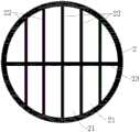
在一些实施方式中,请参考图3-4,换热管2内设有至少一个固定板22,固定板22沿换热管2的长度方向延伸,固定板22的相对两侧分别与换热管2的内侧壁固定连接,换热管2的内部通过固定板22隔断形成多个冷媒通道21。例如,固定板22为多个,多个固定板22依次间隔并行设置于换热管2内,以使换热管2的管道隔断成多个冷媒通道21,各冷媒通道21与换热管2的管道相比,横截面面积较小,以使冷媒流过冷媒通道21时扰动较大,从而增大冷媒流过换热管2的扰动,以使冷媒的热量有效传递到换热管2的管壁,增大换热面积以提高换热效果。In some embodiments, please refer to FIGS. 3-4 , the
进一步地,在一些实施方式中,请参考图3-4,换热管2内设有加强板23,加强板23沿换热管2的长度方向延伸,加强板23的相对两侧分别与换热管2的内侧壁固定连接,加强板23与固定板22相互交错设置以使换热管2的横截面呈格栅状。加强板23与固定板22相互交错进一步缩小冷媒通道21的横截面面积,以进一步增大冷媒流过冷媒通道21的扰动。同时加强板23用于固定相邻两个固定板22之间的位置,以提高换热管2的整体强度,避免换热管2受压发生形变。Further, in some embodiments, please refer to FIGS. 3-4 , the
在一些实施方式中,换热管2、固定板22及加强板23为一体成型结构,提高整体强度,避免固定板22及加强板23发生形变。例如换热管2、固定板22及加强板23通过铸造工艺形成。In some embodiments, the
在一些实施方式中,请参考图3-4,换热管2的内侧壁呈光滑状或凸齿状。凸齿状的换热管2能够增大冷媒与换热管2的内侧壁之间的接触面积,进一步提高换热效果。In some embodiments, please refer to FIGS. 3-4 , the inner wall of the
在一些实施方式中,换热管2为直线形圆管,直线形圆管能够避免发生局部折弯,从而减小冷媒流经换热管2时的分流阻力。此时固定板22及加强板23分别为直线形板体。In some embodiments, the
在一些实施方式中,请参考图2,本实用新型的换热器还包括多个依次间隔设置的翅片6,各换热管2依次穿过多个翅片6。翅片6为铝片,用于增大换热管2与外界空气的换热面积,从而提高换热效果。其中,翅片6上开设有多个供换热管2穿过的穿孔。In some embodiments, please refer to FIG. 2 , the heat exchanger of the present invention further includes a plurality of
进一步地,在一些实施方式中,换热管2通过胀管机与翅片6实现胀接。换热管2通过膨胀的方式卡紧于翅片6的穿孔,相比于采用焊接的方式,胀接的方式操作简单快捷,同时可拆性高,便于后期维护。Further, in some embodiments, the
在一些实施方式中,第一腔室111和第二腔室112位于同一个集流管1的两端,以使进口管4及出口管5同时布设于一个集流管1上,结构布局更为有序合理。In some embodiments, the
本实用新型提供了一种换热器,其将换热管2的管道分割成多个冷媒通道21,各冷媒通道21的横截面较小,采用多个冷媒通道21同时传输冷媒,在确保冷媒流量的情况下通过缩小冷媒通道21的横截面面积来增大冷媒流过换热管2的扰动,以使冷媒的热量有效传递到换热管2的管壁,增大换热面积以提高换热效果。换热管2的两端分别采用集流管1进行分流,以使换热管2可以采用直线形管体,换热管2避免了采用弯折部及弯管进行分流,分流阻力变小,提高了冷媒的流动效率,从而提高换热效果。同时,本实用新型的分流形式能够灵活多变,避免了传统管翅式换热器只能在弯管一侧设置管组件进行分流的缺点,增大了换热器的使用范围及安装便捷性。The utility model provides a heat exchanger, which divides the pipeline of the
为了实现上述目的,本实用新型还提供了一种空调器,包括室内机和室外机,所述室内机或所述室外机包括上面所述的换热器。In order to achieve the above purpose, the present invention also provides an air conditioner comprising an indoor unit and an outdoor unit, wherein the indoor unit or the outdoor unit includes the above-mentioned heat exchanger.
在本说明书的描述中,参考术语“一个实施例”、“一些实施例”、“示意性实施例”、“示例”、“具体示例”、或“一些示例”等的描述意指结合该实施例或示例描述的具体特征、结构、材料或者特点包含于本实用新型的至少一个实施例或示例中。在本说明书中,对上述术语的示意性表述不一定指的是相同的实施例或示例。而且,描述的具体特征、结构、材料或者特点可以在任何的一个或多个实施例或示例中以合适的方式结合。In the description of this specification, reference to the terms "one embodiment," "some embodiments," "exemplary embodiment," "example," "specific example," or "some examples," or the like, is meant to incorporate the embodiment. A particular feature, structure, material, or characteristic described by an example or example is included in at least one embodiment or example of the present invention. In this specification, schematic representations of the above terms do not necessarily refer to the same embodiment or example. Furthermore, the particular features, structures, materials or characteristics described may be combined in any suitable manner in any one or more embodiments or examples.
尽管已经示出和描述了本实用新型的实施例,本领域的普通技术人员可以理解:在不脱离本实用新型的原理和宗旨的情况下可以对这些实施例进行多种变化、修改、替换和变型,本实用新型的范围由权利要求及其等同物限定。Although embodiments of the present invention have been shown and described, it will be understood by those skilled in the art that various changes, modifications, substitutions and alterations can be made in these embodiments without departing from the principles and spirit of the present invention. Variations, the scope of the present invention is defined by the claims and their equivalents.
Claims (10)
Priority Applications (1)
| Application Number | Priority Date | Filing Date | Title |
|---|---|---|---|
| CN202122056782.9UCN216282901U (en) | 2021-08-27 | 2021-08-27 | Heat exchanger and air conditioner |
Applications Claiming Priority (1)
| Application Number | Priority Date | Filing Date | Title |
|---|---|---|---|
| CN202122056782.9UCN216282901U (en) | 2021-08-27 | 2021-08-27 | Heat exchanger and air conditioner |
Publications (1)
| Publication Number | Publication Date |
|---|---|
| CN216282901Utrue CN216282901U (en) | 2022-04-12 |
Family
ID=81062544
Family Applications (1)
| Application Number | Title | Priority Date | Filing Date |
|---|---|---|---|
| CN202122056782.9UActiveCN216282901U (en) | 2021-08-27 | 2021-08-27 | Heat exchanger and air conditioner |
Country Status (1)
| Country | Link |
|---|---|
| CN (1) | CN216282901U (en) |
- 2021
- 2021-08-27CNCN202122056782.9Upatent/CN216282901U/enactiveActive
Similar Documents
| Publication | Publication Date | Title |
|---|---|---|
| CN101672553A (en) | Parallel stream heat exchanger integrated with microchannel and outer fin | |
| CN102445100A (en) | Heat exchange tube unit, finned tube air-cooled condenser and cooling air evaporator | |
| CN111561831A (en) | L-shaped baffle plate shell-and-tube heat exchanger and application thereof | |
| CN111336841A (en) | A wrap-around microchannel heat exchanger | |
| CN211855020U (en) | Heat exchange tube and heat exchanger having the same | |
| CN216282901U (en) | Heat exchanger and air conditioner | |
| CN201724474U (en) | Heat exchanger of air conditioner | |
| CN202254497U (en) | Heat exchanger | |
| CN216694561U (en) | Heat exchanger and air conditioning system with same | |
| CN114646152A (en) | Heat exchanger and air conditioner | |
| CN204329416U (en) | Parallel-flow heat exchanger | |
| WO2023208073A1 (en) | Heat exchanger | |
| CN215177074U (en) | Microchannel heat exchanger and air conditioner | |
| CN211204965U (en) | A parallel flow heat exchanger, heat exchange system and dehumidifier | |
| CN108344210B (en) | Parallel flow heat exchange system for improving heat exchange efficiency | |
| CN210688819U (en) | Heat exchanger and air conditioner with same | |
| CN212721006U (en) | L-shaped baffle plate shell-and-tube heat exchanger | |
| CN103759471A (en) | Air conditioner heat exchanger with foam metal fins | |
| CN212227383U (en) | A heat exchanger and air conditioning system | |
| CN209512581U (en) | Gas-liquid counter current heat-exchanger rig | |
| CN217109793U (en) | Heat exchanger and air conditioner | |
| CN207180100U (en) | A kind of cross-fin tubular type air-cooler with bleed | |
| CN219265060U (en) | Cold trap adopting H-shaped finned tube | |
| CN212390656U (en) | A high-efficiency heat exchange condenser and its heat pipe machine and heat pipe air conditioner integrated machine | |
| CN112066599A (en) | Heat exchanger and air conditioner |
Legal Events
| Date | Code | Title | Description |
|---|---|---|---|
| GR01 | Patent grant | ||
| GR01 | Patent grant |