CN212230582U - Battery self-heating device and vehicle having the same - Google Patents
Battery self-heating device and vehicle having the sameDownload PDFInfo
- Publication number
- CN212230582U CN212230582UCN202020965213.9UCN202020965213UCN212230582UCN 212230582 UCN212230582 UCN 212230582UCN 202020965213 UCN202020965213 UCN 202020965213UCN 212230582 UCN212230582 UCN 212230582U
- Authority
- CN
- China
- Prior art keywords
- battery pack
- switch tube
- power switch
- battery
- heating
- Prior art date
- Legal status (The legal status is an assumption and is not a legal conclusion. Google has not performed a legal analysis and makes no representation as to the accuracy of the status listed.)
- Active
Links
Images


Classifications
- Y—GENERAL TAGGING OF NEW TECHNOLOGICAL DEVELOPMENTS; GENERAL TAGGING OF CROSS-SECTIONAL TECHNOLOGIES SPANNING OVER SEVERAL SECTIONS OF THE IPC; TECHNICAL SUBJECTS COVERED BY FORMER USPC CROSS-REFERENCE ART COLLECTIONS [XRACs] AND DIGESTS
- Y02—TECHNOLOGIES OR APPLICATIONS FOR MITIGATION OR ADAPTATION AGAINST CLIMATE CHANGE
- Y02E—REDUCTION OF GREENHOUSE GAS [GHG] EMISSIONS, RELATED TO ENERGY GENERATION, TRANSMISSION OR DISTRIBUTION
- Y02E60/00—Enabling technologies; Technologies with a potential or indirect contribution to GHG emissions mitigation
- Y02E60/10—Energy storage using batteries
Landscapes
- Secondary Cells (AREA)
Abstract
Description
Translated fromChinese技术领域technical field
本实用新型涉及电动汽车技术领域,尤其涉及一种电池自加热装置和具有该电池自加热装置的车辆。The utility model relates to the technical field of electric vehicles, in particular to a battery self-heating device and a vehicle having the battery self-heating device.
背景技术Background technique
动力电池作为动力来源,在纯电动系列和混合动力系列车型的能源系统上得到大范围使用。然而,动力电池的外特性会受到低温环境温度的影响,续航里程下降,并在直流充电过程中会产生析锂,对电池造成永久性伤害,降低电池的寿命和容量。因此低温环境下,在使用电池前,尤其是在低温充电前,需要对电池进行加热升温处理,使电池电芯温度上升,使其充电能力随温度上升而恢复正常。As a power source, power batteries are widely used in the energy systems of pure electric series and hybrid series models. However, the external characteristics of the power battery will be affected by the low temperature ambient temperature, the cruising range will be reduced, and lithium precipitation will occur during the DC charging process, causing permanent damage to the battery and reducing the battery life and capacity. Therefore, in a low temperature environment, before using the battery, especially before charging at a low temperature, it is necessary to heat the battery to increase the temperature of the battery cells, so that the charging capacity returns to normal as the temperature rises.
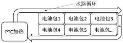
相关技术中,通常采用PTC(Positive Temperature Coefficient,正温度系数)加热方案,即通过PTC加热水路,再通过水路循环对电池进行热量传递,使得电池模组从外壳至内心,由外及内温度上升,PTC加热方案示意图如图1所示。但是,通过上述PTC加热水路间接加热电池,其升温时间较久,导致热交换效率低。In the related art, the PTC (Positive Temperature Coefficient) heating scheme is usually adopted, that is, the water circuit is heated by PTC, and then the heat is transferred to the battery through the circulation of the water circuit, so that the temperature of the battery module rises from the outer casing to the inner core, from the outside to the inside. , the schematic diagram of the PTC heating scheme is shown in Figure 1. However, when the battery is indirectly heated through the above-mentioned PTC heating water path, the heating time is long, resulting in low heat exchange efficiency.
发明内容SUMMARY OF THE INVENTION
本实用新型旨在至少在一定程度上解决上述的技术问题之一。The present invention aims to solve one of the above-mentioned technical problems at least to a certain extent.
第一方面,本实用新型实施例提出了一种电池自加热装置,包括:In the first aspect, an embodiment of the present utility model provides a battery self-heating device, including:
加热电路,所述加热电路的一端与电池包连接,所述加热电路的另一端与电网连接;a heating circuit, one end of the heating circuit is connected to the battery pack, and the other end of the heating circuit is connected to the power grid;
控制模块,所述控制模块与所述加热电路通讯连接;其中,所述控制模块通过所述加热电路控制所述电网和所述电池包之间的能量流动方向,以在所述电池包侧产生交流电流,其中,产生的交流电流流经所述电池包时用以对所述电池包进行加热。a control module, the control module is connected in communication with the heating circuit; wherein, the control module controls the energy flow direction between the power grid and the battery pack through the heating circuit, so as to generate electricity on the battery pack side an alternating current, wherein the generated alternating current flows through the battery pack to heat the battery pack.
本实用新型实施例的电池自加热装置,可通过在电池包的端口上连接一个加热电路,这样,通过利用该加热电路即可实现电池包与电网之间的能量流动,使得电池包内部有循环往复且可控的交流电流流过,使其内电阻迅速发热,使得电池包由于内部电池内阻产生热量的原因而使得电池迅速升温,达到电池包自加热的效果,可以大大缩短低温环境下电池升温时间,使电池可以在较短时间内恢复充电能力。In the battery self-heating device of the embodiment of the present invention, a heating circuit can be connected to the port of the battery pack, so that the energy flow between the battery pack and the power grid can be realized by using the heating circuit, so that there is a circulation inside the battery pack. The reciprocating and controllable AC current flows through, making the internal resistance heat up rapidly, so that the battery pack heats up rapidly due to the heat generated by the internal battery resistance, so as to achieve the effect of self-heating of the battery pack, which can greatly shorten the battery life in low temperature environment The heating time allows the battery to recover its charging capability in a relatively short time.
另外,根据本实用新型上述实施例的电池自加热装置还可以具有如下附加的技术特征:In addition, the battery self-heating device according to the above embodiment of the present invention may also have the following additional technical features:
在本实用新型的一些实施例中,所述加热电路包括:功率因数校正电路和双向DCDC变换器,其中,所述功率因数校正电路的一端与所述电网连接,所述功率因数校正电路的另一端与所述双向DCDC变换器的一端连接,所述双向DCDC变换器的另一端与所述电池包连接。In some embodiments of the present invention, the heating circuit includes: a power factor correction circuit and a bidirectional DCDC converter, wherein one end of the power factor correction circuit is connected to the power grid, and the other end of the power factor correction circuit is connected to the power grid. One end is connected to one end of the bidirectional DCDC converter, and the other end of the bidirectional DCDC converter is connected to the battery pack.
在本实用新型的一些实施例中,所述功率因数校正电路包括:第一电感L1、第二电感L2、第一功率开关管Q1、第二功率开关管Q2、第三功率开关管Q3、第四功率开关管Q4、第五功率开关管Q5和第六功率开关管Q6,其中,In some embodiments of the present invention, the power factor correction circuit includes: a first inductor L1, a second inductor L2, a first power switch transistor Q1, a second power switch transistor Q2, a third power switch transistor Q3, a Four power switch transistors Q4, fifth power switch transistor Q5 and sixth power switch transistor Q6, wherein,
所述第一电感L1的第一端连接在所述电网的第一端,所述第一电感L1的第二端连接在所述第一功率开关管Q1的第一端和所述第二功率开关管Q2的第一端;The first end of the first inductor L1 is connected to the first end of the power grid, and the second end of the first inductor L1 is connected to the first end of the first power switch tube Q1 and the second power The first end of the switch tube Q2;
所述第一功率开关管Q1的第二端连接在所述第三功率开关管Q3的第一端和所述第五功率开关管Q5的第一端;The second end of the first power switch tube Q1 is connected to the first end of the third power switch tube Q3 and the first end of the fifth power switch tube Q5;
所述第二电感L2的第一端连接在所述电网的第一端,所述第二电感L2的第二端连接在所述第四功率开关管Q4的第一端和所述第三功率开关管Q3的第二端,所述第四功率开关管Q4的第二端连接在所述第二功率开关管Q2的第二端;The first end of the second inductor L2 is connected to the first end of the power grid, and the second end of the second inductor L2 is connected to the first end of the fourth power switch tube Q4 and the third power the second end of the switch tube Q3, the second end of the fourth power switch tube Q4 is connected to the second end of the second power switch tube Q2;
所述第五功率开关管Q5的第二端和所述第六功率开关管Q6的第一端连接在与所述电网的第二端,所述第六功率开关管Q6的第二端连接在所述第四功率开关管Q4的第二端。The second end of the fifth power switch tube Q5 and the first end of the sixth power switch tube Q6 are connected to the second end of the power grid, and the second end of the sixth power switch tube Q6 is connected to the second end of the fourth power switch tube Q4.
在本实用新型的实施例中,所述双向DCDC变换器包括:第一开关管T1和第二开关管T2串联组成的第一桥臂,第三开关管T3和第四开关管T4串联组成的第二桥臂,第五开关管T5和第六开关管T6串联组成的第三桥臂,第七开关管T7和第八开关管T8串联组成的第四桥臂,以及变压器T,其中,In the embodiment of the present invention, the bidirectional DCDC converter includes: a first bridge arm composed of a first switch tube T1 and a second switch tube T2 in series, and a third switch tube T3 and a fourth switch tube T4 composed of a series connection. The second bridge arm, the third bridge arm formed by the fifth switch tube T5 and the sixth switch tube T6 in series, the fourth bridge arm formed by the seventh switch tube T7 and the eighth switch tube T8 in series, and the transformer T, wherein,
所述第一桥臂的第一端连接在所述第五功率开关管Q5的第一端,所述第一桥臂的第二端连接在所述第六功率开关管Q6的第二端,所述第一桥臂的半桥中点连接至所述变压器T原边的一端;The first end of the first bridge arm is connected to the first end of the fifth power switch tube Q5, the second end of the first bridge arm is connected to the second end of the sixth power switch tube Q6, The mid-point of the half-bridge of the first bridge arm is connected to one end of the primary side of the transformer T;
所述第二桥臂的第一端连接在所述第五功率开关管Q5的第一端,所述第二桥臂的第二端连接在所述第六功率开关管Q6的第二端,所述第二桥臂的半桥中点连接至所述变压器T原边的另一端;The first end of the second bridge arm is connected to the first end of the fifth power switch tube Q5, the second end of the second bridge arm is connected to the second end of the sixth power switch tube Q6, The half-bridge midpoint of the second bridge arm is connected to the other end of the primary side of the transformer T;
所述变压器T副边的一端连接至所述第四桥臂的半桥中点,所述变压器T副边的另一端连接至所述第三桥臂的半桥中点;所述第三桥臂的两端分别连接在所述电池包的正、负两端,所述第四桥臂的两端分别连接在所述电池包的正、负两端。One end of the secondary side of the transformer T is connected to the midpoint of the half-bridge of the fourth bridge arm, and the other end of the secondary side of the transformer T is connected to the midpoint of the half-bridge of the third bridge arm; the third bridge The two ends of the arm are respectively connected to the positive and negative ends of the battery pack, and the two ends of the fourth bridge arm are respectively connected to the positive and negative ends of the battery pack.
在本实用新型的一些实施例中,所述加热电路为双向车载充电器。In some embodiments of the present invention, the heating circuit is a bidirectional vehicle charger.
在本实用新型的一些实施例中,所述加热电路为双向逆变装置。In some embodiments of the present invention, the heating circuit is a bidirectional inverter device.
在本实用新型的一些实施例中,所述电池自加热装置还包括:In some embodiments of the present invention, the battery self-heating device further includes:
温度传感器,所述温度传感器分别与所述电池包和所述控制模块连接,所述温度传感器用于测量所述电池包的温度,并将测量的所述电池包的温度发送给所述控制模块;a temperature sensor, the temperature sensor is respectively connected to the battery pack and the control module, the temperature sensor is used to measure the temperature of the battery pack, and sends the measured temperature of the battery pack to the control module ;
其中,所述控制模块根据所述温度传感器测量的所述电池包的温度,控制所述加热电路工作。Wherein, the control module controls the heating circuit to work according to the temperature of the battery pack measured by the temperature sensor.
在本实用新型的实施例中,所述控制模块在所述温度传感器测量的所述电池包的温度小于第一阈值时,控制所述加热电路在正向工作状态和反向工作状态之间进行切换,以调整所述电网和所述电池包之间的能量流动方向,并在所述温度传感器测量的电池包的温度大于第二阈值时,控制所述加热电路停止工作;其中,第二阈值大于或等于第一阈值。In an embodiment of the present invention, when the temperature of the battery pack measured by the temperature sensor is less than a first threshold, the control module controls the heating circuit to perform operation between a forward working state and a reverse working state switching to adjust the energy flow direction between the power grid and the battery pack, and when the temperature of the battery pack measured by the temperature sensor is greater than a second threshold, the heating circuit is controlled to stop working; wherein the second threshold greater than or equal to the first threshold.
在本实用新型的实施例中,所述加热电路每次处于所述正向工作状态的第一时长、以及每次处于所述反向工作状态的第二时长相同,且所述第一时长和所述第二时长是由所述电池包最大能够承受的交流电频率决定的。In the embodiment of the present invention, the first duration of each time the heating circuit is in the forward working state and the second duration of each time the heating circuit is in the reverse working state are the same, and the first duration and the The second duration is determined by the maximum AC frequency that the battery pack can withstand.
第二方面,本实用新型实施例还提出了一种车辆,该车辆包括上述第一方面实施例所述的电池自加热装置。In a second aspect, an embodiment of the present invention further provides a vehicle, which includes the battery self-heating device described in the embodiment of the first aspect.
本实用新型附加的方面和优点将在下面的描述中部分给出,部分将从下面的描述中变得明显,或通过本实用新型的实践了解到。Additional aspects and advantages of the present invention will be set forth, in part, from the following description, and in part will become apparent from the following description, or may be learned by practice of the invention.
附图说明Description of drawings
本实用新型上述的和/或附加的方面和优点从下面结合附图对实施例的描述中将变得明显和容易理解,其中:The above and/or additional aspects and advantages of the present invention will become apparent and readily understood from the following description of embodiments taken in conjunction with the accompanying drawings, wherein:
图1为现有技术中通过PTC及水路循环给电池包加热的示例图。FIG. 1 is an example diagram of heating a battery pack through PTC and water circulation in the prior art.
图2为本实用新型实施例的电池自加热装置的结构框示例图一。FIG. 2 is an example diagram 1 of a structure block of a battery self-heating device according to an embodiment of the present invention.
图3为本实用新型实施例的电池自加热装置的电路示例图一。FIG. 3 is a circuit example diagram 1 of the battery self-heating device according to the embodiment of the present invention.
图4为本实用新型实施例的电池自加热装置的电路示例图二。FIG. 4 is a second circuit example of the battery self-heating device according to the embodiment of the present invention.
图5为本实用新型实施例的电池自加热装置的结构框示例图二。FIG. 5 is a second exemplary structural block diagram of the battery self-heating device according to the embodiment of the present invention.
图6为本实用新型实施例的电网与电池包之间的能量流动的示例图一。FIG. 6 is an example diagram 1 of energy flow between a power grid and a battery pack according to an embodiment of the present invention.
图7为本实用新型实施例的电网与电池包之间的能量流动的示例图二。FIG. 7 is an example diagram 2 of energy flow between a power grid and a battery pack according to an embodiment of the present invention.
图8为本实用新型实施例的车辆的结构示意图。FIG. 8 is a schematic structural diagram of a vehicle according to an embodiment of the present invention.
具体实施方式Detailed ways
下面详细描述本实用新型的实施例,所述实施例的示例在附图中示出,其中自始至终相同或类似的标号表示相同或类似的元件或具有相同或类似功能的元件。下面通过参考附图描述的实施例是示例性的,旨在用于解释本实用新型,而不能理解为对本实用新型的限制。The following describes in detail the embodiments of the present invention, examples of which are illustrated in the accompanying drawings, wherein the same or similar reference numerals refer to the same or similar elements or elements having the same or similar functions throughout. The embodiments described below with reference to the accompanying drawings are exemplary, and are intended to be used to explain the present invention, but should not be construed as a limitation of the present invention.
下面参考附图描述本实用新型实施例的电池自加热装置和具有该电池自加热装置的车辆。The following describes a battery self-heating device and a vehicle having the battery self-heating device according to an embodiment of the present invention with reference to the accompanying drawings.
图2是根据本实用新型实施例的电池自加热装置的结构示意图。如图2所示,该电池自加热装置100可以包括:加热电路10和控制模块20。其中,如图2所示,加热电路10的一端与电池包1连接,加热电路10的另一端与电网AC连接;控制模块20与加热电路10通讯连接。需要说明的是,在本实用新型中,上述加热电路可为双向车载充电器或双向逆变装置。为了避免安全隐患,加热电路10还需通过接地线接地。FIG. 2 is a schematic structural diagram of a battery self-heating device according to an embodiment of the present invention. As shown in FIG. 2 , the battery self-
在本实用新型中,控制模块20可通过加热电路10控制电网AC和电池包1之间的能量流动方向,以在电池包1侧产生交流电流,其中,产生的交流电流流经电池包1时用以对电池包1进行加热。也就是说,可利用加热电路10实现电池包1与电网AC之间的能量流动,电池包1内部有循环往复且可控的交流电流流过,使电池包1内电阻迅速发热,从而可以使得电池包内的电池迅速升温。In the present invention, the
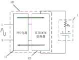
需要说明的是,在本实用新型中,该加热电路10可包括PFC(Power FactorCorrection,功率因数校正)电路11和双向DCDC变换器12。其中,功率因数校正电路11的一端与电网AC连接,功率因数校正电路11的另一端与双向DCDC变换器12的一端连接,双向DCDC变换器12的另一端与电池包1连接。例如,如图3所示,为电池自加热装置的电路示例图一,其中,加热电路10可包括功率因数校正电路11和双向DCDC变换器12,功率因数校正电路11的两端分别连接在电网AC的火线端和零线端,双向DCDC变换器12的初级侧两端分别连接在功率因数校正电路11的两端,双向DCDC变换器12的次级侧两端分别连接在电池包1的正、负两端。It should be noted that, in the present invention, the
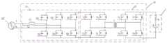
如图4所示,为本实用新型实施例的电池自加热装置的电路示例图二。其中,功率因数校正电路11可包括:第一电感L1、第二电感L2、第一功率开关管Q1、第二功率开关管Q2、第三功率开关管Q3、第四功率开关管Q4、第五功率开关管Q5和第六功率开关管Q6。其中,第一电感L1的第一端连接在电网AC的第一端(如火线端),第一电感L1的第二端连接在第一功率开关管Q1的第一端和第二功率开关管Q2的第一端;第一功率开关管Q1的第二端连接在第三功率开关管Q3的第一端和第五功率开关管Q5的第一端;第二电感L2的第一端连接在电网AC的第一端(如火线端),第二电感L2的第二端连接在第四功率开关管Q4的第一端和第三功率开关管Q3的第二端,第四功率开关管Q4的第二端连接在第二功率开关管Q2的第二端;第五功率开关管Q5的第二端和第六功率开关管Q6的第一端连接在与电网AC的第二端(如零线端),第六功率开关管Q6的第二端连接在第四功率开关管Q4的第二端。As shown in FIG. 4 , it is a second circuit example of the battery self-heating device according to the embodiment of the present invention. The power
如图4所示,双向DCDC变换器12可包括:第一开关管T1和第二开关管T2串联组成的第一桥臂,第三开关管T3和第四开关管T4串联组成的第二桥臂,第五开关管T5和第六开关管T6串联组成的第三桥臂,第七开关管T7和第八开关管T8串联组成的第四桥臂,以及变压器T。其中,第一桥臂的第一端连接在第五功率开关管Q5的第一端,第一桥臂的第二端连接在第六功率开关管Q6的第二端,第一桥臂的半桥中点连接至变压器T原边的一端;第二桥臂的第一端连接在第五功率开关管Q5的第一端,第二桥臂的第二端连接在第六功率开关管Q6的第二端,第二桥臂的半桥中点连接至变压器T原边的另一端;变压器T副边的一端连接至第四桥臂的半桥中点,变压器T副边的另一端连接至第三桥臂的半桥中点;第三桥臂的两端分别连接在电池包1的正、负两端,第四桥臂的两端分别连接在电池包1的正、负两端。As shown in FIG. 4 , the
在本实用新型中,控制模块可通过控制功率因数校正电路中的功率开关管和双向DCDC变换器中的开关管的通断,来切换电网和电池包之间的能量流动方向,从而使得在电池包侧产生交流电流,其中,产生的交流电流流经电池包时可用以对电池包进行加热,从而达到电池包自加热的效果。In the present invention, the control module can switch the energy flow direction between the power grid and the battery pack by controlling the on-off of the power switch tube in the power factor correction circuit and the switch tube in the bidirectional DCDC converter, so that the battery An alternating current is generated on the pack side, wherein the generated alternating current can be used to heat the battery pack when flowing through the battery pack, so as to achieve the effect of self-heating of the battery pack.
在本实用新型中,如图5所示,该电池自加热装置100还可包括:温度传感器30。其中,温度传感器30可分别与电池包1和控制模块20连接,温度传感器30可用于测量电池包1的温度,并将测量的电池包1的温度发送给控制模块20;其中,控制模块20根据温度传感器30测量的电池包1的温度,控制加热电路10工作。在本实用新型中,温度传感器40所测量的电池包1的温度,可为电池包1的平均温度,该平均温度可由电池包1中所有电池单元的温度求平均而得到的。In the present invention, as shown in FIG. 5 , the battery self-
举例而言,控制模块20在接收到温度传感器30发送的电池包1的温度时,可根据电池包1的当前温度,来判断当前是否需要对电池包1进行自加热,比如,在判断电池包1的当前温度小于第一阈值时,可认为电池包当前处于低温环境下,此时可控制功率因数校正电路中的功率开关管和双向DCDC变换器中的开关管的通断工作,以使加热电路在正向工作状态和反向工作状态之间进行切换,以调整电网和电池包之间的能量流动方向。For example, when the
在通过控制模块20控制加热电路10在正向工作状态和反向工作状态之间进行切换的过程中,温度传感器40可实时测量电池包1的温度,并将实时测量到的温度发送给控制模块20。当控制模块20在判断电池包1的当前温度大于第二阈值(其中,该第二阈值大于或等于上述第一阈值)时,控制加热电路10停止工作,即说明此时电池包1已升温,电池包内芯温度能够满足使用要求,使得电池包的充放电能力随温度上升恢复正常。也就是说,当电池包的温度T达到第二阈值,即预设温度T1时,控制模块可控制加热电路停止工作,针对电池包的充放电过程终止。In the process of controlling the
在本实用新型中,以加热电路包括功率因数校正电路和双向DCDC变换器为例。第一阶段,控制模块控制加热电路进行正向工作。加热电路处于正向工作状态时,电网与电池包之间的能量流动可为顺时针方向,例如,如图6所示,箭头表示为能量流动方向。此时,电网AC通过加热电路10向电池包1进行充电。设定每次针对电池包的充电时长Δt1,当充电时长t=Δt1时,控制模块控制加热电路停止正向工作,此时针对电池包的充电停止,并控制加热电路从正向工作状态切换到反向工作状态。In the present invention, the heating circuit includes a power factor correction circuit and a bidirectional DCDC converter as an example. In the first stage, the control module controls the heating circuit to work forward. When the heating circuit is in the forward working state, the energy flow between the power grid and the battery pack can be clockwise. For example, as shown in FIG. 6 , the arrow indicates the energy flow direction. At this time, the power grid AC charges the
第二阶段,控制模块控制加热电路进行反向工作。加热电路处于反向工作状态时,电网与电池包之间的能量流动可为逆时针方向,例如,如图7所示,箭头表示为能量流动方向。此时,电池包1通过反向工作的加热电路10回馈能量到电网AC,即在此阶段实现电池包的放电。设定每次针对电池包的放电时长Δt2,当放电时长t=Δt2时,控制模块控制加热电路停止反向工作,此时针对电池包的放电停止。之后,循环往复上述第一阶段和第二阶段,此时在系统产生交流电流,通过调节加热电路中双向DCDC变换器的增益,控制输出电流,使其保持为正弦波或方波,电流方向顺时针、逆时针往复交替,交流电流流经电池包内阻,功率P=I2R(其中,I取交流有效值,R为电池包内阻),电池包内阻功耗可使电池温度上升,从而达到电池包自加热的效果。In the second stage, the control module controls the heating circuit to work in reverse. When the heating circuit is in the reverse working state, the energy flow between the power grid and the battery pack can be in a counterclockwise direction, for example, as shown in FIG. 7 , the arrows indicate the energy flow direction. At this time, the
需要说明的是,在本实用新型中,加热电路每次处于正向工作状态的第一时长、以及每次处于反向工作状态的第二时长相同,且第一时长和第二时长是由电池包最大能够承受的交流电频率决定的。也就是说,假设每次利用电网通过加热电路向电池包进行充电(即每当加热电路处于正向工作状态)时,充电时长(即上述第一时长)为Δt1,每次利用电池包通过反向工作的加热电路回馈能量到电网时,电池包的放电时长(即上述第二时长)为Δt2,Δt1与Δt2应满足:Δt1=Δt2。其中,第一时长Δt1和第二时长Δt2可分别是由电池包最大能够承受的交流电频率来决定的,其中,电池包最大能够承受的交流电频率比如可为100赫兹。可以理解,低温环境下充电会对电池有极大损耗,会产生析锂使电池寿命降低。针对于车用锂离子电池充放电,频率较高时,电流增大不会对电池造成任何损伤,频率越高越不容易产生析锂现象。因此,基于该特性,为了能够似的电网和电池包之间产生正反向流动的交流电流,通过产生的交流电流使得电池包内阻产生热量,从而使电池包温度上升,本实用新型中,该交流电流频率可为100赫兹。It should be noted that, in the present invention, the first duration of the heating circuit in the forward working state and the second duration of the reverse working state are the same each time, and the first duration and the second duration are determined by the battery. It is determined by the maximum AC frequency that the package can withstand. That is to say, it is assumed that each time the power grid is used to charge the battery pack through the heating circuit (that is, whenever the heating circuit is in the forward working state), the charging time (that is, the first duration above) is Δt1, and each time the battery pack is used to pass the reverse operation When feeding energy back to the power grid from the working heating circuit, the discharge duration of the battery pack (ie, the second duration) is Δt2, and Δt1 and Δt2 should satisfy: Δt1=Δt2. The first duration Δt1 and the second duration Δt2 may be respectively determined by the maximum AC frequency that the battery pack can withstand, wherein the maximum AC frequency that the battery pack can withstand may be, for example, 100 Hz. It can be understood that charging in a low temperature environment will cause great loss of the battery, which will cause lithium precipitation and reduce the battery life. For the charging and discharging of lithium-ion batteries for vehicles, when the frequency is high, the current increase will not cause any damage to the battery, and the higher the frequency, the less likely to cause lithium precipitation. Therefore, based on this characteristic, in order to generate an alternating current flowing in the forward and reverse directions between the power grid and the battery pack, the generated alternating current causes the internal resistance of the battery pack to generate heat, thereby increasing the temperature of the battery pack. In the present invention, The frequency of the alternating current may be 100 Hz.
本实用新型实施例的电池自加热装置,可通过在电池包的端口上连接一个加热电路,这样,通过利用该加热电路即可实现电池包与电网之间的能量流动,使得电池包内部有循环往复且可控的交流电流流过,使其内电阻迅速发热,使得电池包由于内部电池内阻产生热量的原因而使得电池迅速升温,达到电池包自加热的效果,可以大大缩短低温环境下电池升温时间,使电池可以在较短时间内恢复充电能力。In the battery self-heating device of the embodiment of the present invention, a heating circuit can be connected to the port of the battery pack, so that the energy flow between the battery pack and the power grid can be realized by using the heating circuit, so that there is a circulation inside the battery pack. The reciprocating and controllable AC current flows through, making the internal resistance heat up rapidly, so that the battery pack heats up rapidly due to the heat generated by the internal battery resistance, so as to achieve the effect of self-heating of the battery pack, which can greatly shorten the battery life in low temperature environment The heating time allows the battery to recover its charging capability in a relatively short time.
为了实现上述实施例,本实用新型还提出了一种车辆。In order to realize the above embodiments, the present invention also provides a vehicle.
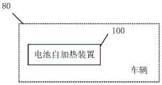
图8是根据本实用新型实施例的车辆的结构示意图。如图8所示,该车辆80可包括:电池自加热装置100。其中,该电池自加热装置100的结构以及功能描述可参见上述本实用新型任一实施例所述的电池自加热装置的结构和功能描述,在此不再赘述。需要说明的是,上述车辆可为纯电动汽车,还可以是混合动力汽车。8 is a schematic structural diagram of a vehicle according to an embodiment of the present invention. As shown in FIG. 8 , the
根据本实用新型的车辆,可通过在电池包的端口上连接一个加热电路,这样,通过利用该加热电路即可实现电池包与电网之间的能量流动,使得电池包内部有循环往复且可控的交流电流流过,使其内电阻迅速发热,使得电池包由于内部电池内阻产生热量的原因而使得电池迅速升温,达到电池包自加热的效果,可以大大缩短低温环境下电池升温时间,使电池可以在较短时间内恢复充电能力。According to the vehicle of the present invention, a heating circuit can be connected to the port of the battery pack, so that the energy flow between the battery pack and the power grid can be realized by using the heating circuit, so that the inside of the battery pack is reciprocating and controllable. The AC current flows through the battery pack, causing the internal resistance to heat up rapidly, so that the battery pack heats up rapidly due to the heat generated by the internal battery resistance, so as to achieve the effect of self-heating of the battery pack, which can greatly shorten the battery heating time in a low temperature environment, making the battery pack heat up. The battery can be restored to charging capacity in a relatively short period of time.
在本实用新型的描述中,需要理解的是,术语“第一”、“第二”、“第三”、“第四”、“第五”、“第六”、“第七”、“第八”仅用于描述目的,而不能理解为指示或暗示相对重要性或者隐含指明所指示的技术特征的数量。由此,限定有“第一”、“第二”、“第三”、“第四”、“第五”、“第六”、“第七”、“第八”的特征可以明示或者隐含地包括至少一个该特征。In the description of the present invention, it should be understood that the terms "first", "second", "third", "fourth", "fifth", "sixth", "seventh", " "Eighth" is for descriptive purposes only, and cannot be understood as indicating or implying relative importance or implying the number of indicated technical features. Thus, the features defined as "first", "second", "third", "fourth", "fifth", "sixth", "seventh", and "eighth" can be expressed or implied. Inclusively at least one of these features is included.
在本实用新型中,除非另有明确的规定和限定,术语“安装”、“相连”、“连接”、“固定”等术语应做广义理解,例如,可以是固定连接,也可以是可拆卸连接,或成一体;可以是机械连接,也可以是电连接;可以是直接相连,也可以通过中间媒介间接相连,可以是两个元件内部的连通或两个元件的相互作用关系,除非另有明确的限定。对于本领域的普通技术人员而言,可以根据具体情况理解上述术语在本实用新型中的具体含义。In the present utility model, unless otherwise expressly specified and limited, the terms "installation", "connection", "connection", "fixed" and other terms should be understood in a broad sense, for example, it may be a fixed connection or a detachable connection connected, or integrated; it can be a mechanical connection or an electrical connection; it can be directly connected or indirectly connected through an intermediate medium, it can be the internal communication between two elements or the interaction between the two elements, unless otherwise clearly defined. For those of ordinary skill in the art, the specific meanings of the above terms in the present invention can be understood according to specific situations.
在本说明书的描述中,参考术语“一个实施例”、“一些实施例”、“示例”、“具体示例”、或“一些示例”等的描述意指结合该实施例或示例描述的具体特征、结构、材料或者特点包含于本实用新型的至少一个实施例或示例中。在本说明书中,对上述术语的示意性表述不必须针对的是相同的实施例或示例。而且,描述的具体特征、结构、材料或者特点可以在任一个或多个实施例或示例中以合适的方式结合。此外,在不相互矛盾的情况下,本领域的技术人员可以将本说明书中描述的不同实施例或示例以及不同实施例或示例的特征进行结合和组合。In the description of this specification, description with reference to the terms "one embodiment," "some embodiments," "example," "specific example," or "some examples", etc., mean specific features described in connection with the embodiment or example , structure, material or feature is included in at least one embodiment or example of the present invention. In this specification, schematic representations of the above terms are not necessarily directed to the same embodiment or example. Furthermore, the particular features, structures, materials or characteristics described may be combined in any suitable manner in any one or more embodiments or examples. Furthermore, those skilled in the art may combine and combine the different embodiments or examples described in this specification, as well as the features of the different embodiments or examples, without conflicting each other.
尽管上面已经示出和描述了本实用新型的实施例,可以理解的是,上述实施例是示例性的,不能理解为对本实用新型的限制,本领域的普通技术人员在本实用新型的范围内可以对上述实施例进行变化、修改、替换和变型。Although the embodiments of the present invention have been shown and described above, it should be understood that the above embodiments are exemplary and should not be construed as limitations of the present invention, and those of ordinary skill in the art are within the scope of the present invention Variations, modifications, substitutions and variations can be made to the above-described embodiments.
Claims (10)
Priority Applications (1)
| Application Number | Priority Date | Filing Date | Title |
|---|---|---|---|
| CN202020965213.9UCN212230582U (en) | 2020-05-29 | 2020-05-29 | Battery self-heating device and vehicle having the same |
Applications Claiming Priority (1)
| Application Number | Priority Date | Filing Date | Title |
|---|---|---|---|
| CN202020965213.9UCN212230582U (en) | 2020-05-29 | 2020-05-29 | Battery self-heating device and vehicle having the same |
Publications (1)
| Publication Number | Publication Date |
|---|---|
| CN212230582Utrue CN212230582U (en) | 2020-12-25 |
Family
ID=73930649
Family Applications (1)
| Application Number | Title | Priority Date | Filing Date |
|---|---|---|---|
| CN202020965213.9UActiveCN212230582U (en) | 2020-05-29 | 2020-05-29 | Battery self-heating device and vehicle having the same |
Country Status (1)
| Country | Link |
|---|---|
| CN (1) | CN212230582U (en) |
Cited By (5)
| Publication number | Priority date | Publication date | Assignee | Title |
|---|---|---|---|---|
| CN113060048A (en)* | 2021-04-30 | 2021-07-02 | 重庆长安新能源汽车科技有限公司 | Power battery pulse heating system and control method thereof |
| CN114834310A (en)* | 2022-04-14 | 2022-08-02 | 华为数字能源技术有限公司 | Heating method and device for power battery of electric automobile |
| CN116097543A (en)* | 2022-01-27 | 2023-05-09 | 宁德时代新能源科技股份有限公司 | Charging device and method for heating battery |
| US20230294557A1 (en)* | 2020-07-28 | 2023-09-21 | Byd Company Limited | Automobile battery thermal management system, automobile thermal management system, and electric automobile |
| DE102023122523B3 (en) | 2023-08-23 | 2025-02-20 | Dr. Ing. H.C. F. Porsche Aktiengesellschaft | Method for operating a battery and device |
- 2020
- 2020-05-29CNCN202020965213.9Upatent/CN212230582U/enactiveActive
Cited By (7)
| Publication number | Priority date | Publication date | Assignee | Title |
|---|---|---|---|---|
| US20230294557A1 (en)* | 2020-07-28 | 2023-09-21 | Byd Company Limited | Automobile battery thermal management system, automobile thermal management system, and electric automobile |
| CN113060048A (en)* | 2021-04-30 | 2021-07-02 | 重庆长安新能源汽车科技有限公司 | Power battery pulse heating system and control method thereof |
| CN113060048B (en)* | 2021-04-30 | 2022-06-14 | 重庆长安新能源汽车科技有限公司 | Power battery pulse heating system and control method thereof |
| CN116097543A (en)* | 2022-01-27 | 2023-05-09 | 宁德时代新能源科技股份有限公司 | Charging device and method for heating battery |
| WO2023141870A1 (en)* | 2022-01-27 | 2023-08-03 | 宁德时代新能源科技股份有限公司 | Charging device and method for heating battery |
| CN114834310A (en)* | 2022-04-14 | 2022-08-02 | 华为数字能源技术有限公司 | Heating method and device for power battery of electric automobile |
| DE102023122523B3 (en) | 2023-08-23 | 2025-02-20 | Dr. Ing. H.C. F. Porsche Aktiengesellschaft | Method for operating a battery and device |
Similar Documents
| Publication | Publication Date | Title |
|---|---|---|
| CN212230582U (en) | Battery self-heating device and vehicle having the same | |
| CN212373187U (en) | Battery self-heating devices and vehicles | |
| CN108511822B (en) | Low temperature heating device for lithium ion battery and electric vehicle | |
| CN212229493U (en) | Battery self-heating device and vehicle having the same | |
| CN108777339B (en) | A kind of lithium-ion battery pulse discharge self-heating method and device | |
| CN203721849U (en) | Alternating current heating circuit for power battery charger | |
| CN204289653U (en) | A kind of heating of battery structure being built in motor driven systems | |
| CN113506934A (en) | Lithium battery heating system and heating method | |
| CN107845840A (en) | Battery heater circuit | |
| CN112622559B (en) | Automobile and high-voltage control device | |
| CN112186305B (en) | Low-temperature battery hybrid self-heating device and self-heating method based on same | |
| CN113809765B (en) | Energy storage system and self-heating method | |
| CN104779652A (en) | Power battery charger by using AC charging and discharging for quick preheating | |
| CN203721845U (en) | Alternating current charge-discharge low-temperature heating circuit for boost-type DC-DC (direct current-direct current) power battery | |
| WO2021244649A1 (en) | Energy conversion apparatus and safety control method therefor | |
| WO2024178978A1 (en) | Electric vehicle direct-current charging heating system and control method therefor | |
| CN207967253U (en) | Battery pack low-temperature heating device, battery module and vehicle | |
| CN207459113U (en) | Battery heater circuit | |
| CN108039538A (en) | Vehicle mounted dynamic battery low temperature exchange heating-equilibrium integration topology and method | |
| CN113540621A (en) | A low-temperature self-heating device and method for a lithium battery with sinusoidal AC | |
| CN115064797B (en) | A battery low temperature starting method and system without external power supply | |
| CN203722291U (en) | Boost type alternating current low temperature heating circuit for power battery module | |
| CN213734672U (en) | Power battery heating device, direct current charging pile and electric vehicle charging system | |
| CN113871757B (en) | Battery heating system and battery heating method thereof | |
| CN218731293U (en) | Battery self-heating circuit and vehicle |
Legal Events
| Date | Code | Title | Description |
|---|---|---|---|
| GR01 | Patent grant | ||
| GR01 | Patent grant |