CN211960893U - An electronic cigarette component - Google Patents
An electronic cigarette componentDownload PDFInfo
- Publication number
- CN211960893U CN211960893UCN201921885687.6UCN201921885687UCN211960893UCN 211960893 UCN211960893 UCN 211960893UCN 201921885687 UCN201921885687 UCN 201921885687UCN 211960893 UCN211960893 UCN 211960893U
- Authority
- CN
- China
- Prior art keywords
- fixing member
- structural module
- gap
- electronic cigarette
- casing
- Prior art date
- Legal status (The legal status is an assumption and is not a legal conclusion. Google has not performed a legal analysis and makes no representation as to the accuracy of the status listed.)
- Expired - Fee Related
Links
- 239000003571electronic cigaretteSubstances0.000titleclaimsabstractdescription46
- 239000011796hollow space materialSubstances0.000claimsabstractdescription28
- 230000002093peripheral effectEffects0.000claimsdescription12
- 238000000034methodMethods0.000description13
- 238000010438heat treatmentMethods0.000description12
- 239000000443aerosolSubstances0.000description6
- 238000007789sealingMethods0.000description6
- 238000004519manufacturing processMethods0.000description5
- 239000000853adhesiveSubstances0.000description4
- 230000001070adhesive effectEffects0.000description4
- 238000010586diagramMethods0.000description4
- 230000008569processEffects0.000description4
- 238000003860storageMethods0.000description3
- 229910000838Al alloyInorganic materials0.000description2
- 238000000889atomisationMethods0.000description2
- 230000008859changeEffects0.000description2
- 238000006073displacement reactionMethods0.000description2
- 230000000694effectsEffects0.000description2
- 230000005389magnetismEffects0.000description2
- 239000000463materialSubstances0.000description2
- 229910052751metalInorganic materials0.000description2
- 239000002184metalSubstances0.000description2
- 239000010935stainless steelSubstances0.000description2
- 229910001220stainless steelInorganic materials0.000description2
- RYGMFSIKBFXOCR-UHFFFAOYSA-NCopperChemical compound[Cu]RYGMFSIKBFXOCR-UHFFFAOYSA-N0.000description1
- 244000043261Hevea brasiliensisSpecies0.000description1
- 230000009471actionEffects0.000description1
- 230000004075alterationEffects0.000description1
- 229910052782aluminiumInorganic materials0.000description1
- XAGFODPZIPBFFR-UHFFFAOYSA-NaluminiumChemical compound[Al]XAGFODPZIPBFFR-UHFFFAOYSA-N0.000description1
- 230000015572biosynthetic processEffects0.000description1
- 238000004891communicationMethods0.000description1
- 238000010276constructionMethods0.000description1
- 239000010949copperSubstances0.000description1
- 229910052802copperInorganic materials0.000description1
- 230000003247decreasing effectEffects0.000description1
- 238000005553drillingMethods0.000description1
- 238000001125extrusionMethods0.000description1
- 239000012530fluidSubstances0.000description1
- 230000006870functionEffects0.000description1
- 239000003292glueSubstances0.000description1
- 239000007769metal materialSubstances0.000description1
- 229920003052natural elastomerPolymers0.000description1
- 229920001194natural rubberPolymers0.000description1
- 238000005192partitionMethods0.000description1
- 230000000149penetrating effectEffects0.000description1
- 239000004033plasticSubstances0.000description1
- 238000003825pressingMethods0.000description1
- 238000004080punchingMethods0.000description1
- 239000002994raw materialSubstances0.000description1
- 239000000779smokeSubstances0.000description1
- 230000003238somatosensory effectEffects0.000description1
- 238000006467substitution reactionMethods0.000description1
- 229920003051synthetic elastomerPolymers0.000description1
- 239000005061synthetic rubberSubstances0.000description1
Images


Landscapes
- Battery Mounting, Suspending (AREA)
Abstract
Translated fromChinese
Description
Translated fromChinese技术领域technical field
本揭露大体上涉及一种电子烟部件内的固定构件,具体而言涉及一种用于提供可吸入气雾(aerosol)的电子烟的电子烟部件内的固定构件。The present disclosure generally relates to a securing member in an electronic cigarette component, and more particularly, to a securing member in an electronic cigarette component for providing an electronic cigarette that is inhalable aerosol.
背景技术Background technique
电子烟系一种电子产品,其将可挥发性溶液加热雾化并产生气雾以供用户吸食。近年来,各大厂商开始生产各式各样的电子烟产品。一般而言,一电子烟产品包括外壳、储油室、雾化室、加热组件、进气口、气流通道、出气口、电源装置、感测装置及控制装置。储油室用于储存可挥发性溶液,加热组件用于将可挥发性溶液加热雾化并产生气雾。进气口与雾化室彼此连通,当使用者吸气时提供空气给加热组件。由加热组件产生之气雾首先产生于雾化室内,随后经由气流通道及出气口被使用者吸入。电源装置提供加热组件所需之电力,控制装置根据感测装置侦测到的用户吸气动作,控制加热组件的加热时间。外壳则包覆上述各个组件。An electronic cigarette is an electronic product that heats and atomizes a volatile solution and generates aerosol for users to smoke. In recent years, major manufacturers have begun to produce a variety of electronic cigarette products. Generally speaking, an electronic cigarette product includes a housing, an oil storage chamber, an atomizing chamber, a heating element, an air inlet, an air passage, an air outlet, a power supply device, a sensing device and a control device. The oil storage chamber is used to store the volatile solution, and the heating component is used to heat and atomize the volatile solution and generate aerosol. The air inlet and the atomizing chamber communicate with each other and provide air to the heating assembly when the user inhales. The aerosol generated by the heating element is first generated in the atomizing chamber, and then inhaled by the user through the airflow channel and the air outlet. The power supply device provides the power required by the heating element, and the control device controls the heating time of the heating element according to the user's inhalation action detected by the sensing device. The casing covers the above components.
现有的电子烟产品存在不同的缺陷。举例言之,若有需要将前述例如电源装置、感测装置及控制装置等组件形成的结构模块固定于外壳中之特定位置时,通常利用黏着剂黏着固定于外壳中的预定位置,或是利用在外壳上打出一个以上的穿孔,并以柱销件插入穿过外壳上的穿孔,而接合或插入欲固定之内部组件的相应位置上,而实现将内部组件固定于外壳中之预定位置的目的,并且使得所欲固定的内部组件经固定后不会相对于外壳在任何使用状态下产生移动。然而,现行的固定方式之缺陷在于若利用黏着剂的固定方式,则可能因为黏着工序的不当进行导致欲固定组件的固定位置难以精准统一或是容易产生溢胶的问题。另外,利用黏着剂的固定方式亦有可能在电子烟经过长时间的使用后,黏着剂的因为电子烟使用温度的关系导致变质,而影响固着效果。Existing vaping products have different flaws. For example, if it is necessary to fix the structural module formed by the aforementioned components such as the power supply device, the sensing device, and the control device to a specific position in the casing, it is usually fixed at the predetermined position in the casing by using an adhesive, or using an adhesive. Punch more than one perforation on the outer shell, and insert a pin through the perforation on the outer shell to engage or insert into the corresponding position of the internal component to be fixed, so as to achieve the purpose of fixing the internal component in the predetermined position in the shell , and the internal components to be fixed will not move relative to the shell in any state of use after being fixed. However, the disadvantage of the current fixing method is that if the fixing method using the adhesive is used, the fixing position of the component to be fixed may be difficult to be accurately unified or the problem of glue overflow may occur due to the improper execution of the bonding process. In addition, the fixing method using the adhesive may also deteriorate after the electronic cigarette is used for a long time due to the temperature of the electronic cigarette, which will affect the fixing effect.
至于利用在电子烟之外壳上打出一个以上的穿孔,并插入柱销件将内部组件固定于外壳上之方式,则因为必须增加对外壳钻孔,并且插入柱销件以供固定之工序。此种工序将增加产品制造的时间。另外,因为电子烟之外壳较为轻薄的关系,钻孔的难度较高,容易对外壳造成破坏而降低良率,并且此种固定方式对于柱销件与孔洞之间的密合精度亦有要求,而导致制造成本的上升。As for the method of punching more than one perforation on the outer casing of the electronic cigarette and inserting a pin member to fix the internal components on the outer casing, it is necessary to increase the process of drilling holes in the outer casing and inserting the pin member for fixing. Such a process will increase the time to manufacture the product. In addition, because the casing of the electronic cigarette is relatively light and thin, it is difficult to drill holes, which is easy to damage the casing and reduce the yield, and this fixing method also has requirements for the tightness between the pin and the hole. resulting in an increase in manufacturing costs.
鉴于上述问题,本申请提出一种用于快速固定电子烟之内部组件或结构模块的固定构件。In view of the above problems, the present application proposes a fixing member for quickly fixing internal components or structural modules of an electronic cigarette.
实用新型内容Utility model content
本揭露之一目的在于提供一种用于固定电子烟部件的内部结构模块的固定构件,使得电子烟部件的内部结构模块在任何使用状态下,不会与电子烟之外壳产生相对滑动或移动。One objective of the present disclosure is to provide a fixing member for fixing the internal structure module of the electronic cigarette component, so that the internal structure module of the electronic cigarette component will not slide or move relative to the casing of the electronic cigarette under any use state.
基于上述目的,本揭露提出一种电子烟部件,其特征在于:一外壳,其具有一中空空间;一结构模块,其设置于所述外壳的所述中空空间的一预定位置;一固定构件,所述固定构件组装至所述结构模块,并将所述结构模块固定于所述外壳的所述中空空间中的所述预定位置。Based on the above purpose, the present disclosure provides an electronic cigarette component, which is characterized by: a casing having a hollow space; a structural module disposed at a predetermined position of the hollow space of the casing; a fixing member, The fixing member is assembled to the structural module and fixes the structural module at the predetermined position in the hollow space of the housing.
附图说明Description of drawings
当结合附图阅读时,从以下详细描述容易理解本揭露的各方面。应注意,各种特征可能未按比例绘制,且各种特征的尺寸可出于论述的清楚起见而任意增大或减小。Aspects of the present disclosure are readily understood from the following detailed description when read in conjunction with the accompanying drawings. It should be noted that the various features may not be drawn to scale and that the dimensions of the various features may be arbitrarily increased or decreased for clarity of discussion.
图1显示根据本揭露的一实施例的电子烟的示意图。FIG. 1 shows a schematic diagram of an electronic cigarette according to an embodiment of the present disclosure.
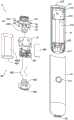
图2A显示根据本揭露的一实施例的电子烟的主体的组件组装图。FIG. 2A shows a component assembly diagram of the main body of the electronic cigarette according to an embodiment of the present disclosure.
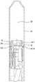
图2B显示图2A中的组件组合为主体的型态的截面图。FIG. 2B shows a cross-sectional view of the configuration in which the components in FIG. 2A are assembled into a body.
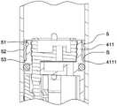
图3A及3B显示图2A中所示的结构模块的组件图。3A and 3B show component diagrams of the structural module shown in FIG. 2A.
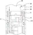
图4显示结构模块位于外壳中的部分放大截面图。Figure 4 shows a partially enlarged cross-sectional view of the structural module in the housing.
图5显示固定构件插入间隙以固定结构模块的部分放大截面图。FIG. 5 shows a partially enlarged cross-sectional view of the fixing member inserted into the gap to fix the structural module.
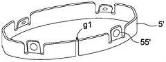
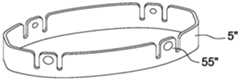
图6显示了根据本揭露的一实施例的固定构件。FIG. 6 shows a fixing member according to an embodiment of the present disclosure.
图7显示固定构件开始进入外壳的内壁与环状壁的间的间隙的部分放大截面图。Figure 7 shows a partially enlarged cross-sectional view of the securing member beginning to enter the gap between the inner wall of the housing and the annular wall.
图8显示固定构件组装连接至结构模块的环状壁的部分放大截面图。Figure 8 shows a partially enlarged cross-sectional view of the fixed member assembled to the annular wall of the structural module.
图9显示外壳的内壁与环状壁之间的间隙的尺寸的部分放大截面图。Figure 9 is a partially enlarged cross-sectional view showing the dimensions of the gap between the inner wall of the housing and the annular wall.
图10显示图6的固定结构的部分放大图。FIG. 10 shows a partial enlarged view of the fixing structure of FIG. 6 .
图11A至11C显示本揭露的其他实施例的固定构件。11A to 11C show fixing members of other embodiments of the present disclosure.
图12显示根据本揭露另一实施例的主体的外壳的结构的部分放大截面图。12 is a partially enlarged cross-sectional view showing a structure of a casing of a main body according to another embodiment of the present disclosure.
图13A显示根据本揭露另一实施例的结构模块与固定构件的结构型态的截面图。FIG. 13A shows a cross-sectional view of the structure of a structural module and a fixing member according to another embodiment of the present disclosure.
图13B为图13A的结构的部分放大截面图。13B is an enlarged partial cross-sectional view of the structure of FIG. 13A.
图14显示了根据本揭露的其他实施例的固定构件。FIG. 14 shows fixing members according to other embodiments of the present disclosure.
图15显示根据本揭露的另一实施例的固定构件组装连接至环状壁的部分放大截面图。15 shows a partially enlarged cross-sectional view of a fixing member assembled to an annular wall according to another embodiment of the present disclosure.
贯穿图式和详细描述使用共同参考标号来指示相同或类似组件。根据以下结合附图作出的详细描述,本揭露的特点将更为明显。Common reference numerals are used throughout the drawings and the detailed description to refer to the same or similar components. The features of the present disclosure will become more apparent from the following detailed description in conjunction with the accompanying drawings.
具体实施方式Detailed ways
以下公开内容提供用于实施所提供的标的物的不同特征的许多不同实施例或实例。下文描述组件和布置的特定实例。当然,这些仅是实例且并不意图为限制性的。在本揭露中,在以下描述中对第一特征在第二特征之上或上的形成的参考可包含第一特征与第二特征直接接触形成的实施例,并且还可包含额外特征可形成于第一特征与第二特征之间从而使得第一特征与第二特征可不直接接触的实施例。另外,本揭露可能在各个实例中重复参考标号和/或字母。此重复是出于简化和清楚的目的,且本身并不指示所论述的各种实施例和/或配置之间的关系。The following disclosure provides many different embodiments or examples for implementing different features of the provided subject matter. Specific examples of components and arrangements are described below. Of course, these are only examples and are not intended to be limiting. In the present disclosure, references in the following description to the formation of a first feature on or on a second feature may include embodiments in which the first feature is formed in direct contact with the second feature, and may also include additional features that may be formed on Embodiments between the first feature and the second feature such that the first feature and the second feature may not be in direct contact. Additionally, the present disclosure may repeat reference numerals and/or letters in various instances. This repetition is for the purpose of simplicity and clarity, and does not in itself indicate a relationship between the various embodiments and/or configurations discussed.
下文详细论述本揭露的实施例。然而,应了解,本揭露提供了可在多种多样的特定情境中实施的许多适用的概念。所论述的特定实施例仅仅是说明性的且并不限制本揭露的范围。Embodiments of the present disclosure are discussed in detail below. It should be appreciated, however, that the present disclosure provides many applicable concepts that can be embodied in a wide variety of specific contexts. The specific embodiments discussed are illustrative only and do not limit the scope of the disclosure.
图1说明根据本揭露的一些实施例的电子烟的示意图。1 illustrates a schematic diagram of an electronic cigarette according to some embodiments of the present disclosure.
电子烟1可由烟弹(cartridge)2及主体3等部件组成。在一实施例中,烟弹2及主体3两种部件可设计为一个整体。在另一实施例中,烟弹2及主体3可设计成分开的两组件,而烟弹2可设计成可移除地与主体3结合。此外,在其他实施例中,当烟弹2与主体3结合时,烟弹2可设计为其一部分收纳于主体3中的结构型态。例如在图1所示之电子烟1之结构中,烟弹2由烟嘴盖21、烟弹外壳22及设置于烟弹外壳22内的一内部模块23所构成。烟弹2的烟弹外壳22及内部模块23可形成或包含可挥发性溶液的储存舱、密封组件、雾化室、加热组件顶盖、加热组件、加热组件底座及烟弹底座等组件(未图标)。藉由烟弹2可将可挥发性溶液加热雾化并产生气雾,烟弹具有与雾化室彼此连通的进气口,当使用者吸气时提供空气给加热组件。由加热组件产生之气雾首先产生于雾化室内,随后经由气流通道及出气口被使用者吸入。The electronic cigarette 1 may be composed of a cartridge 2 and a
依照图1所揭示之结构,烟弹2之外壳22可沿主体3的纵向方向插入主体3之外壳31之中空空间32中,使烟弹2可移除地组装收纳于主体3中,以形成电子烟1之整体结构。According to the structure disclosed in FIG. 1 , the
图2A说明根据本揭露的一些实施例的电子烟部件的主体3的组件组装图,图2B 则显示图2A中之组件组合为主体3的型态之截面图。如图2A及图2B所示,主体3 之组件包含外壳31、结构模块4、及固定构件5。外壳31为内部界定有一中空空间32 的薄型壳体,且如图2A及2B所示,外壳31沿其纵向方向的下方末端处界定有一与中空空间32连通的开口33。外壳31之薄型壳体可以采用但不限于金属材料,例如铝、铝合金、不锈钢等。FIG. 2A illustrates an assembly view of the
图3A及3B显示了图2A中所示的结构模块4之零件图。应了解,图2A至3B所显示的结构模块4仅为一例示性结构,并非用以限制电子烟中类似结构模块的细部组成组件。如图3A及3B中所示,结构模块4包含结构模块支架41、传感器模块42、密封组件43、导电组件44、磁性组件45、电源子模块46、及电路板支架47。传感器模块 42包含传感器上盖421及传感器422。电源子模块46则包含电路板461、扁平电缆462、震动器463、充电组件464、电池组件465、及缓冲组件466。Figures 3A and 3B show a component view of the
结构模块支架41之顶部具有一环状壁411之部分,环状壁411中间凹入以界定用以承纳传感器上盖421于其中的一空腔412,而结构模块支架41在环状壁411下方沿着周围方向形成有一沟槽413,用以容纳密封组件43于其中。环状壁411的顶端表面设有孔洞h1,用以容纳磁性组件45于其中。磁性组件45可以是本身具有磁性的永久磁铁,或是在通电之后才具有磁性的电磁铁。磁性组件45用于吸附例如烟弹2之内部模块23下端对应位置之金属件24,以可移除地结合烟弹2与本体3。The top of the
传感器上盖421具有孔h2及h3。孔h2可以容纳导电组件44。孔h3与传感器422 流体连通。传感器422可以经由孔h3侦测气流产生、气压变化、或是声波等等性质变化。The sensor
电路板461设置于电路板支架47及结构模块支架41之间。电路板461上包含控制器C。控制器C可以是一种微处理器、可程序化集成电路、或可程序化逻辑电路。在某些实施例中,控制器C内的运算逻辑在控制器C制造后便无法更改。在某些实施例中,控制器C内的运算逻辑在控制器C制造后可程序化更改。The
电路板461上亦可包含内存(图中未显示)。在某些实施例中,内存可整合于控制器C内。在某些实施例中,内存可与控制器C分开设置。A memory (not shown) may also be included on the
控制器C可与传感器422电连接,并可与导电组件44电连接。控制器C亦电连接至电池组件465。当传感器422侦测到气流产生、气压变化或是声波时,控制器C可以控制电池组件465输出功率至导电组件44。例如,当传感器422侦测到一负压时,控制器C可以控制电池组件465输出功率至导电组件44。又当控制器C判定传感器422 侦测到之气压低于一临限值时,控制器C可以控制电池组件465输出功率至导电组件 44。又当控制器C判定传感器422侦测到之声波之振幅高于一临限值时,控制器C可以控制电池组件465输出功率至导电组件44。Controller C can be electrically connected to
震动器463可电连接至控制器C。在某些实施例中,震动器463经由扁平电缆462 电连接至电路板461上的控制器C。根据电子烟1的不同操作状态,控制器C可以控制震动器463产生不同的体感效果。在某些实施例中,当使用者吸气超过一特定时间长度时,控制器C可控制震动器463产生震动以提醒使用者停止吸气。在某些实施例中,当用户对电子烟1进行充电时,控制器C可控制震动器463产生震动以指示充电已经开始。在某些实施例中,当电子烟1充电已经完成时,控制器C可控制震动器463产生震动以指示充电已经完成。The
充电组件464用于对电池组件465进行充电。充电组件464之一端经由位于主体3之外壳31之下端之通孔33暴露,藉此使用者可藉由将供电连接器连接至充电组件464 而对电池组件465进行充电。在某些实施例中,充电组件464包含USB接口。在某些实施例中,充电组件464包含USB Type-C接口。The charging
现参阅图3A,结构模块支架41沿其纵向方向更依序具有一第一容纳空间414、一第二容纳空间415、一第三容纳空间416及一第四容纳空间417。第一容纳空间414位于沟槽413的下方。第一容纳空间414可容纳传感器422、电路板462及导电组件44。特别是,结构模块支架41可与电路板支架47结合以形成第一容纳空间414并包覆传感器422、电路板462及导电组件44。电池组件465可卡置于结构模块支架41上并设置于第二容纳空间415中,震动器463可卡置于结构模块支架41上并设置第三容纳空间 416中,而充电组件464则可卡置于结构模块支架41上并设置于第四容纳空间417中。如图3A所示,容纳空间414、415、416及417系藉由肋条或隔板加以分隔界定。此外,一缓冲组件466可设置于电池组件465的表面465S上,而当电池组件465装设于结构模块支架41的第二容纳空间415中时,缓冲组件466位于电池组件465与主体3之外壳31之内壁间。缓冲组件466直接接触主体3之外壳31之内壁34。虽然图中未显示,可以思及一额外缓冲组件可设置于电池组件465及结构组件支架41之间。Referring now to FIG. 3A , the
另外,主体3之外壳31包含透光孔311。透光孔311可包含一或多个穿透外壳31 之孔。在某些实施例中,透光孔311可呈现大体上圆形之穿孔。在某些实施例中,透光孔311可呈现大体上矩形之穿孔。在某些实施例中,透光孔311可呈现对称外型之穿孔。在某些实施例中,透光孔311可呈现不对称外型之穿孔。由电路板461上可具有一或多个发光组件,发光组件发出之光经由透光孔311射出而为使用者之肉眼可视(visible)。In addition, the
由图2A及图2B可知,组装好的结构模块4沿着主体3之外壳31的纵向方向插入外壳31的中空空间32中,直到充电组件464位于外壳31底端之开口33之可供用户进行充电作业之位置。此时,结构模块4位于外壳31中之预定组装位置,而如图2B所示,位于结构模块支架之凹槽413之密封组件43之外侧接触形成外壳31之中空空间32之内壁34。2A and 2B, the assembled
固定构件5则在结构模块4插入外壳31中并置于上述预定组装位置后,沿着主体 3之外壳31的纵向方向插入外壳31的中空空间32中,直至固定构件5最终位于结构模块支架41之上方之环状壁411与外壳31之内壁34之间,并且抵顶环状壁411与内壁34之间,而将结构模块4固定于预定组装位置上。The fixing
图4显示结构模块4位于外壳31中之预定组装位置时的部分放大截面图。由图4 可见,当结构模块4位于预定位置时,密封组件43之外侧接触主体3之外壳31之内壁 34,而在纵向方向分隔中空空间32。密封组件43可为天然橡胶或人造橡胶所制,用以在结构模块支架41的沟槽413及主体3之外壳31之内壁34之间提供密封。此外,结构模块支架41之顶端之环状壁411的周围表面,与外壳31之内壁34之间形成截面大致呈现矩形的一间隙g。由图4可知,间隙g沿着环状壁411或内壁34之周围方向延伸,且较佳延伸形成一环状间隙。环状壁411的下方径向向外延伸以形成一止挡部4111,止挡部4111与环状壁411形成一阶梯状结构,而在止挡部4111上形成一止挡表面S。FIG. 4 shows a partially enlarged cross-sectional view of the
图5显示固定构件5沿着外壳31的纵向方向插入间隙g,以将结构模块4固定于预定位置之部分放大截面图。由图5可知,固定构件5组装连接至结构模块4之顶端之环状壁411上,而填充环状壁411与外壳31之内壁34之间隙g,并且利用固定构件5 之内侧表面51及外侧表面52各者之全部或部分以分别接触抵顶环状壁411的外表面及外壳31的内壁34,藉此将结构模块4固定于预定位置上,而使得在例如用户将充电插头插入充电组件464时以进行充电或在其他使用状态下,组装完成后的结构模块4与外壳31之间,不会产生相互的滑动或移动而导致结构模块4离开预定的固定位置。5 shows a partially enlarged cross-sectional view of the fixing
又,由于结构模块支架4的环状壁411的下方具有止挡部4111,当固定构件5沿纵向方向在外壳31的中空空间32向下进入间隙g时,除了分别抵顶于环状壁411的外表面及外壳31的内壁34之外,固定构件5的下表面53最终将抵顶于止挡部4111的止挡表面S,而到达图5所示一停驻位置。藉由固定构件5的下表面53抵顶于止挡部4111 的止挡表面S之结构,当用户从主体3之下方将充电插头插入结构模块4之充电组件 464时,固定构件5之下表面53将可帮助承受来自止挡部4111的向上力量,而进一步防止结构模块4在外壳31的内壁34上滑动而离开预定的固定位置的状况发生。In addition, since there is a
图6显示了根据本揭露之一实施例之固定构件5。如图6所示,固定构件5具有对应于内壁34或间隙g的轮廓或形状的一环状结构,以便能够插入外壳31之内壁34及结构模块支架41之环状壁411之间而固定结构模块4。在其他实施例中,固定构件5 亦可呈现具有对应具有对应于内壁34或间隙g的轮廓或形状的一弧状结构,而非封闭式的环状结构。图6所揭示的固定构件5,具有内侧表面51、外侧表面52、下表面53 及上表面54。另外,固定构件5之上方部分可具有至少一个或是复数个耳片部分55(在图6中,固定构件5具有四个耳片部分55),其径向向内弯折一角度A(见图7),且耳片部分55之两侧具有垂直空隙56。另外,每个耳片部分55上亦可具有一凸部551。径向向内弯折的耳片部分55及其两侧之空隙56,使得耳片部分55具有挠性,而能够朝径向向外方向反折。在图6中,空隙56的底部界定了固定构件5的上方部分与下方部分的分界,且下方部分呈现了一环状结构。固定构件5可由金属制成,例如铝合金、不锈钢或铜等材料制成,亦可使用塑料制成,本揭露并不限定固定结构5之材料,只要所使用的材料使得耳片部分55具有挠性即可。FIG. 6 shows a fixing
图7显示固定构件5开始进入内壁34与结构模块支架41之环状壁411之间的间隙 g中的截面图。图8显示固定构件5进入间隙g并到达抵顶于环状壁411之止挡部4111 之止挡表面S之最终位置时,固定构件5与外壳31及结构模块41的相关位置的部分截面图。由图7及图8可知,在制造电子烟时,当将结构模块4插入外壳31之中空空间 34并且置于预定的组装位置后,固定结构5随后将沿着纵向方向插入外壳31之中空空间34,使固定构件5之环状下方部分开始进入间隙g中。图7展示了固定构件5之环状下方部分进入间隙g的情况,此时固定构件5径向向内弯折的耳片55尚未接触到环状壁411之顶端周缘,因此并未被环状壁411之顶端周缘抵顶而径向向外反折。随着固定构件5继续沿着纵向方向往下推移,结构模块支架41之环状壁411的顶端周缘及周围外表面开始抵顶接触固定构件5之上方部分,并且固定构件5之径向向内弯折之耳片 55开始被环状壁411的顶端周缘及周围外表面径向向外抵顶反折,直到固定构件5之下表面53被止挡于止挡部4111之表面S,而到达最终位置。此时,固定构件5完全进入间隙g中,且耳片55受到环状壁411之抵顶而完全反折成位于间隙g中的大致垂直型态,并且固定构件5的内侧表面51接触抵顶环状壁411之外表面,固定构件5的耳片55之凸部551受到外壳31之内壁34之挤压而变形,因此固定构件5的凸部551接触抵顶外壳315之内壁34。由于耳片55具有挠性,将夹紧环状壁411之外表面,又由于耳片55的凸部551经变形以对内壁34产生挤压的力量,藉此固定构件5可将结构模块 4之位置牢牢固定,防止结构模块4与外壳31产生相对移动或滑动而离开正确之预定组装位置。在图7及图8所示的实施例中,可知固定构件5之径向厚度略小于间隙g之宽度,然藉由凸部551结构之挤压形变,使得固定构件5之内侧表面之一部分抵顶触抵顶环状壁411之外表面,而固定构件5之外侧表面之一部分(在图8中即为产生形变之凸部551之表面部分)接触抵顶外壳31之内壁34,从而将结构模块4之位置牢牢固定。然而,在其他的实施例中,固定构件5的径向厚度可设定为等于间隙g之宽度,使得固定构件5插入间隙g且凸部551经形变后,固定构件5之内侧表面51之全部完全抵顶触抵顶环状壁411之外表面,而固定构件5之外侧表面52之全部亦完全接触抵顶外壳 31之内壁34,从而将结构模块4之位置牢牢固定。FIG. 7 shows a cross-sectional view of the start of the securing
图9显示外壳31的内壁34与结构模块4之环状壁411之间的间隙g的结构尺寸。图10则为图6所示之固定结构5之部分放大图,用以显示其结构尺寸。如图9所示,间隙g具有一宽度W1及一深度D1,宽度W1与固定构件5之厚度相配合,使得固定构件5之内侧表面51之全部或部分接触并抵顶结构模块4之环状壁411的外周面,而外侧表面52的全部或部分接触并抵顶于外壳31的内壁34。例如,可藉由干涉配合或紧配的方式可使固定构件5紧密地卡置于间隙g中,进而使结构模块4紧密地固定于外壳31之中空空间32中的预定位置上。FIG. 9 shows the structural dimension of the gap g between the
间隙g之宽度W1之尺寸可介于0.3mm至1.0mm之间,较佳可介于0.4mm至0.6mm 之间,而其深度D1可藉于1mm至10mm之间,较佳为3mm至5mm之间。又如图10 所示,固定构件5之整体高度H1约可藉于2mm至5mm,较佳为2.5mm至3.5mm之间,空隙56的宽度W2可藉于0.1mm至0.6mm之间,较佳为0.3mm至0.5mm之间,空隙56之深度介于固定构件5之高度H1的1/2至3/4之间。呈现圆顶状之凸部551底部之直径较佳可为0.9mm,而凸部551较佳突出于固定构件5之外侧表面52约0.2mm之高度。此外,凸部55之底部之最上缘距离耳片55之顶缘之距离D3约可为0.3mm。The size of the width W1 of the gap g may be between 0.3mm and 1.0mm, preferably between 0.4mm and 0.6mm, and the depth D1 of the gap g may be between 1mm and 10mm, preferably between 3mm and 5mm. between. Also as shown in FIG. 10 , the overall height H1 of the fixing
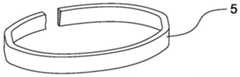
固定构件5并不限于图6所示之型态。图11A、11B及11C显示其他实施例的固定构件型态。在图11A中,固定构件5'之结构型态基本上与图6所示之固定构件5相同,惟其环状体上具有断开一间隔g1,使得固定构件5'并不会呈现封闭的环状体。间隔g1 的尺寸大小必须能使固定构件5'达到将结构模块4固定于外壳31之中空空间32中之目的。图11A所示的固定结构5'能够直接将原材料以冲压模式制成,具有零件制造快速且节省成本之优势。The fixing
图11B所示之固定构件5”与图6所示之固定构件5之差异在于耳片55”并未径向向内弯折一角度。然而,图11B所示之固定构件5”仍然具有凸部551",且固定构件5"之其余尺寸特征,皆可与图6所示之固定构件5相同,因此固定构件5"之内侧表面及外侧表面仍可分别接触并抵顶结构模块4之环状壁411的外周面与外壳31的内壁34,而使固定构件5"紧密地卡置于间隙g中,进而使结构模块4可固定于外壳31之中空空间32 中的预定位置上。The difference between the fixing
图11C所示之固定构件5”'与图6所示之固定构件5之差异在于耳片55”'并未径向向内弯折一角度,且耳片55”'亦未具有凸部结构。因此,固定构件5"'之径向厚度系设置成与间隙g之宽度W1基本相同(例如藉由紧配的尺寸设置方式),而固定构件5的其余尺寸特征,皆可与图6所示之固定构件5相同,因此固定构件5"'之内侧表面及外侧表面仍可分别紧密地接触并抵顶结构模块4之环状壁411的外周面与外壳31的内壁34,而使固定构件5"紧密地卡置于间隙g中,进而使结构模块4可固定于外壳31之中空空间32中的预定位置上。The difference between the fixing
应注意,固定构件之高度可使得当固定构件被插入至外壳31之中空空间32之间隙g中的最终位置时,固定构件之上表面与结构模块4的环状壁411的上表面齐平或共面。然而,在不影响固定构件之固定作用的条件下,固定构件之高度亦可使其在位于最终位置时,固定构件之上表面高于或低于结构模块4的环状壁411的上表面。It should be noted that the height of the fixing member may be such that when the fixing member is inserted into the final position in the gap g of the
本揭露图12显示依据本揭露另一实施例之主体3之外壳31之结构。由图12可知,主体3之外壳31之内侧壁34形成至少一凹槽35,凹槽35于内侧壁34上形成之位置,对应于当固定结构5插入间隙g并且接触抵顶结构模块支架41之环状避411之止檔部表面S时,固定结构5之耳片55之凸部551之位置,以使得凸部551的至少一部分进入凹槽35中,以进一步将结构模块4固定于外壳31之中空空间32中的预定位置上。替代地,凹槽35可为沿着外壳31之内壁34之周围方向延伸的环形凹槽,以容纳固定件5之凸部551的至少一部分,进而固定结构模块4。凹槽35之凹陷深度较佳不超过外壳31之厚度的二分之一。FIG. 12 of the present disclosure shows the structure of the
本揭露之固定构件并不限于前述揭露的固定构件型态。图13A揭露根据本揭露另一实施例的结构模块与固定构件之结构型态。在图13A中,电子烟之本体之构造,除了结构模块支架顶端之环状壁与固定构件之结构型态与先前揭露之型态不同外,其余组件之结构型态皆相同。图13B为图13A之结构的局部放大图,图13B中的结构模块支架41之环状壁411,系自顶端沿纵向方向倾斜延伸至止挡部4111,形成顶端之径向尺寸及周缘尺寸较小,而底部之径向尺寸及周缘尺寸较大之结构型态,从而使得在环状壁 411与外壳31之内壁34之间的间隙g之截面形成了楔形形状,为了配合间隙g之轮廓及楔形形状之截面,固定构件5相应地制成截面具有符合内壁34及间隙g之轮廓及楔形截面的环状或弧状结构(如13B及图14所示),而能够使固定构件5插入间隙g以固定结构模块4时,固定构件5的外侧面接触抵顶外壳31之内壁34,固定构件5的内侧面接触抵顶结构模块41之环状壁411的周围表面,固定构件5的下表面则抵顶止挡部 4111的表面S。固定构件5之尺寸与间隙g的尺寸可设计为例如彼此紧配的尺寸,使得当结构模块41沿着纵向方向插入外壳31的中空空间32并到达预定位置后,固定构件 5沿着纵向方向插入间隙g中到达其停驻位置时,可以紧密地将结构模块固定于外壳31 之中空空间32的预定位置上,如图15所示。在此一实施例中,固定构件5具有上表面径向厚度或径向尺寸较下表面径向厚度或径向尺寸较大的楔形形状,当使用者进行例如以连接器插入充电组件464之动作而欲对电池组件465充电之动作时,将朝纵向方向向上顶推结构模块4,此时固定构件5的楔形形状将能够阻止结构模块4相对于外壳3之内壁32之向上滑移,而能够达到在任何使用状况下均能够固定结构模块4之功效。The fixing member of the present disclosure is not limited to the type of the fixing member disclosed above. FIG. 13A discloses the structure of a structural module and a fixing member according to another embodiment of the present disclosure. In FIG. 13A , the structure of the main body of the electronic cigarette is the same except that the structure of the annular wall and the fixing member at the top of the structural module bracket are different from those previously disclosed. Fig. 13B is a partial enlarged view of the structure of Fig. 13A. The
根据上述本揭露提出之用于电子烟之固定构件,可以简单的组装方法有效固定位于电子烟之外壳内的结构模块之位置,而避免在任何使用状况下结构模块与电子烟之外壳之内壁产生相对地滑移。本揭露之固定构件结构简单,且组装方法相较于习知结构工序简单,可有效节省生产成本并提高生产效率。According to the fixing member for the electronic cigarette proposed in the present disclosure, the position of the structural module located in the casing of the electronic cigarette can be effectively fixed by a simple assembly method, so as to avoid the occurrence of the structural module and the inner wall of the casing of the electronic cigarette under any usage conditions. relatively slip. The fixing member of the present disclosure has a simple structure, and the assembly method is simpler than the conventional structure, which can effectively save the production cost and improve the production efficiency.
如本文中所使用,术语“近似地”、“基本上”、“基本”及“约”用于描述并考虑小变化。当与事件或情况结合使用时,所述术语可指事件或情况精确地发生的例子以及事件或情况极近似地发生的例子。如本文中相对于给定值或范围所使用,术语“约”大体上意味着在给定值或范围的±10%、±5%、±1%或±0.5%内。范围可在本文中表示为自一个端点至另一端点或在两个端点之间。除非另外规定,否则本文中所公开的所有范围包括端点。术语“基本上共面”可指沿同一平面定位的在数微米(μm)内的两个表面,例如,沿着同一平面定位的在10μm内、5μm内、1μm内或0.5μm内。当参考“基本上”相同的数值或特性时,术语可指处于所述值的平均值的±10%、±5%、±1%或±0.5%内的值。As used herein, the terms "approximately," "substantially," "substantially," and "about" are used to describe and account for small variations. When used in conjunction with an event or circumstance, the terms can refer to instances in which the event or circumstance occurs precisely as well as instances in which the event or circumstance occurs closely. As used herein with respect to a given value or range, the term "about" generally means within ±10%, ±5%, ±1%, or ±0.5% of the given value or range. A range may be expressed herein as from one endpoint to the other or between the two endpoints. All ranges disclosed herein are inclusive of the endpoints unless otherwise specified. The term "substantially coplanar" may refer to two surfaces positioned along the same plane within a few micrometers (μm), eg, within 10 μm, 5 μm, 1 μm, or 0.5 μm positioned along the same plane. When referring to "substantially" the same value or property, a term may refer to a value within ±10%, ±5%, ±1%, or ±0.5% of the mean of the stated value.
如本文中所使用,术语“近似地”、“基本上”、“基本”和“约”用于描述和解释小的变化。当与事件或情况结合使用时,所述术语可指事件或情况精确地发生的例子以及事件或情况极近似地发生的例子。举例来说,当与数值结合使用时,术语可指小于或等于所述数值的±10%的变化范围,例如,小于或等于±5%、小于或等于±4%、小于或等于±3%、小于或等于±2%、小于或等于±1%、小于或等于±0.5%、小于或等于±0.1%,或小于或等于±0.05%。举例来说,如果两个数值之间的差小于或等于所述值的平均值的±10%(例如,小于或等于±5%、小于或等于±4%、小于或等于±3%、小于或等于±2%、小于或等于±1%、小于或等于±0.5%、小于或等于±0.1%,或小于或等于±0.05%),那么可认为所述两个数值“基本上”或“约”相同。举例来说,“基本上”平行可以指相对于0°的小于或等于±10°的角度变化范围,例如,小于或等于±5°、小于或等于±4°、小于或等于±3°、小于或等于±2°、小于或等于±1°、小于或等于±0.5°、小于或等于±0.1°,或小于或等于±0.05°。举例来说,“基本上”垂直可以指相对于90°的小于或等于±10°的角度变化范围,例如,小于或等于±5°、小于或等于±4°、小于或等于±3°、小于或等于±2°、小于或等于±1°、小于或等于±0.5°、小于或等于±0.1°,或小于或等于±0.05°。As used herein, the terms "approximately," "substantially," "substantially," and "about" are used to describe and explain small variations. When used in conjunction with an event or circumstance, the terms can refer to instances in which the event or circumstance occurs precisely as well as instances in which the event or circumstance occurs closely. For example, when used in conjunction with a numerical value, a term may refer to a range of variation less than or equal to ±10% of the numerical value, eg, less than or equal to ±5%, less than or equal to ±4%, less than or equal to ±3% , less than or equal to ±2%, less than or equal to ±1%, less than or equal to ±0.5%, less than or equal to ±0.1%, or less than or equal to ±0.05%. For example, if the difference between two values is less than or equal to ±10% of the mean of the values (eg, less than or equal to ±5%, less than or equal to ±4%, less than or equal to ±3%, less than or equal to ±2%, less than or equal to ±1%, less than or equal to ±0.5%, less than or equal to ±0.1%, or less than or equal to ±0.05%), then the two values may be considered to be "substantially" or "substantially" about" is the same. For example, "substantially" parallel may refer to an angular variation range of less than or equal to ±10° relative to 0°, eg, less than or equal to ±5°, less than or equal to ±4°, less than or equal to ±3°, ±2° or less, ±1° or less, ±0.5° or less, ±0.1° or less, or ±0.05° or less. For example, "substantially" vertical may refer to an angular variation range of less than or equal to ±10° relative to 90°, eg, less than or equal to ±5°, less than or equal to ±4°, less than or equal to ±3°, ±2° or less, ±1° or less, ±0.5° or less, ±0.1° or less, or ±0.05° or less.
举例来说,如果两个表面之间的位移等于或小于5μm、等于或小于2μm、等于或小于1μm或等于或小于0.5μm,那么两个表面可以被认为是共面的或基本上共面的。如果表面相对于平面在表面上的任何两个点之间的位移等于或小于5μm、等于或小于2 μm、等于或小于1μm或等于或小于0.5μm,那么可以认为表面是平面的或基本上平面的。For example, two surfaces may be considered coplanar or substantially coplanar if the displacement between the two surfaces is equal to or less than 5 μm, equal to or less than 2 μm, equal to or less than 1 μm, or equal to or less than 0.5 μm . A surface can be considered planar or substantially planar if its displacement relative to the plane between any two points on the surface is 5 μm or less, 2 μm or less, 1 μm or less, or 0.5 μm or less of.
如本文中所使用,除非上下文另外明确规定,否则单数术语“一(a/an)”和“所述”可包含复数指示物。在一些实施例的描述中,提供于另一组件“上”或“上方”的组件可涵盖前一组件直接在后一组件上(例如,与后一组件物理接触)的情况,以及一或多个中间组件位于前一组件与后一组件之间的情况。As used herein, the singular terms "a/an" and "the" can include plural referents unless the context clearly dictates otherwise. In the description of some embodiments, an element that is provided "on" or "over" another element may encompass situations where the former element is directly on (eg, in physical contact with) the latter element, as well as one or more A case where an intermediate component is located between the previous component and the latter component.
如本文中所使用,为易于描述可在本文中使用空间相对术语例如“下面”、“下方”、“下部”、“上方”、“上部”、“下部”、“左侧”、“右侧”等描述如图中所说明的一个组件或特征与另一组件或特征的关系。除图中所描绘的定向之外,空间相对术语意图涵盖在使用或操作中的装置的不同定向。设备可以其它方式定向(旋转90度或处于其它定向),且本文中所使用的空间相对描述词同样可相应地进行解释。应理解,当一组件被称为“连接到”或“耦合到”另一组件时,其可直接连接或耦合到所述另一组件,或可存在中间组件。As used herein, for ease of description, spatially relative terms such as "below", "below", "lower", "above", "upper", "lower", "left side", "right side" may be used herein ” etc. describe the relationship of one component or feature to another component or feature as illustrated in the figures. In addition to the orientation depicted in the figures, the spatially relative terms are intended to encompass different orientations of the device in use or operation. The device may be otherwise oriented (rotated 90 degrees or at other orientations) and the spatially relative descriptors used herein interpreted accordingly. It will be understood that when an element is referred to as being "connected" or "coupled to" another element, it can be directly connected or coupled to the other element or intervening elements may be present.
如本文中所使用,术语“大约”、“基本上”、“大体”以及“约”用以描述和考虑小的变化。当与事件或情形结合使用时,所述术语可以指其中事件或情形明确发生的情况以及其中事件或情形极接近于发生的情况。如在本文中相对于给定值或范围所使用,术语“约”通常意指在给定值或范围的±10%、±5%、±1%或±0.5%内。范围可在本文中表示为从一个端点到另一端点或在两个端点之间。除非另外指定,否则本文中所公开的所有范围包括端点。术语“基本上共面”可指在数微米(μm)内沿同一平面定位,例如在10μm内、 5μm内、1μm内或0.5μm内沿着同一平面的的的两个表面。当参考“基本上”相同的数值或特征时,术语可指处于所述值的平均值的±10%、±5%、±1%或±0.5%内的值。As used herein, the terms "about," "substantially," "substantially," and "about" are used to describe and account for small variations. When used in conjunction with an event or circumstance, the term can refer to both instances in which the event or circumstance clearly occurs and instances in which the event or circumstance occurred in close proximity. As used herein with respect to a given value or range, the term "about" generally means within ±10%, ±5%, ±1%, or ±0.5% of the given value or range. A range may be expressed herein as from one endpoint to the other or between the two endpoints. All ranges disclosed herein are inclusive of the endpoints unless otherwise specified. The term "substantially coplanar" may refer to two surfaces located along the same plane within a few micrometers (μm), eg, within 10 μm, within 5 μm, within 1 μm, or within 0.5 μm along the same plane. When referring to "substantially" the same value or characteristic, a term may refer to a value within ±10%, ±5%, ±1%, or ±0.5% of the mean of the stated value.
前文概述本公开的若干实施例和细节方面的特征。本公开中描述的实施例可容易地用作用于设计或修改其它过程的基础以及用于执行相同或相似目的和/或获得引入本文中的实施例的相同或相似优点的结构。这些等效构造不脱离本公开的精神和范围并且可在不脱离本公开的精神和范围的情况下作出不同变化、替代和改变。The foregoing summarizes features of several embodiments and details of the present disclosure. The embodiments described in this disclosure may readily be used as a basis for designing or modifying other processes and structures for carrying out the same or similar purposes and/or obtaining the same or similar advantages of the embodiments incorporated herein. These equivalent constructions do not depart from the spirit and scope of the present disclosure, and various changes, substitutions and alterations may be made herein without departing from the spirit and scope of the present disclosure.
Claims (12)
Translated fromChinesePriority Applications (1)
| Application Number | Priority Date | Filing Date | Title |
|---|---|---|---|
| CN201921885687.6UCN211960893U (en) | 2019-11-04 | 2019-11-04 | An electronic cigarette component |
Applications Claiming Priority (1)
| Application Number | Priority Date | Filing Date | Title |
|---|---|---|---|
| CN201921885687.6UCN211960893U (en) | 2019-11-04 | 2019-11-04 | An electronic cigarette component |
Publications (1)
| Publication Number | Publication Date |
|---|---|
| CN211960893Utrue CN211960893U (en) | 2020-11-20 |
Family
ID=73352921
Family Applications (1)
| Application Number | Title | Priority Date | Filing Date |
|---|---|---|---|
| CN201921885687.6UExpired - Fee RelatedCN211960893U (en) | 2019-11-04 | 2019-11-04 | An electronic cigarette component |
Country Status (1)
| Country | Link |
|---|---|
| CN (1) | CN211960893U (en) |
Cited By (1)
| Publication number | Priority date | Publication date | Assignee | Title |
|---|---|---|---|---|
| CN110754691A (en)* | 2019-11-04 | 2020-02-07 | 深圳雾芯科技有限公司 | Fixing member for electronic cigarette and fixing method of electronic cigarette component |
- 2019
- 2019-11-04CNCN201921885687.6Upatent/CN211960893U/ennot_activeExpired - Fee Related
Cited By (1)
| Publication number | Priority date | Publication date | Assignee | Title |
|---|---|---|---|---|
| CN110754691A (en)* | 2019-11-04 | 2020-02-07 | 深圳雾芯科技有限公司 | Fixing member for electronic cigarette and fixing method of electronic cigarette component |
Similar Documents
| Publication | Publication Date | Title |
|---|---|---|
| CN206453243U (en) | Cigarette bullet, atomizing component and its electronic cigarette | |
| CN211960893U (en) | An electronic cigarette component | |
| CN206534130U (en) | Battery component and its electronic cigarette | |
| CN204070508U (en) | There is the electronic cigarette case of concealed charging connector | |
| CN209346110U (en) | Battery case and electronic cigarette | |
| CN218773341U (en) | electronic atomization device | |
| WO2021087670A1 (en) | Fixing assembly for electronic cigarette and method for fixing electronic cigarette component | |
| CN216293022U (en) | Electronic cigarette atomization assembly and electronic cigarette | |
| CN110754691A (en) | Fixing member for electronic cigarette and fixing method of electronic cigarette component | |
| CN109998176B (en) | Electronic cigarette and electronic cigarette set with side disassembly and assembly of cigarette cartridge | |
| CN204257923U (en) | Waterproof earphone jack | |
| CN105518357B (en) | Sealing joint for fuel cassette | |
| CN216818470U (en) | A battery case, battery and electronic device | |
| WO2022041985A1 (en) | Vaporization device | |
| CN114732162A (en) | Pneumatic switching devices, control systems and electronic cigarettes | |
| CN205451134U (en) | USB flash disk with push type fingerprint sensor | |
| CN111864959A (en) | A rear cover structure of a diaphragm pump motor | |
| CN221104817U (en) | Annotate liquid lid subassembly, atomizer and electron atomizing device | |
| CN202603097U (en) | Snap-on USB flash drive | |
| TW201712926A (en) | Spacer for batteries | |
| CN218605075U (en) | Atomizer | |
| CN201112429Y (en) | A battery packaging gasket and a battery including the gasket | |
| CN219353064U (en) | Atomizing assembly and atomizing device | |
| CN111972714A (en) | Electronic atomization device | |
| CN206559747U (en) | Household electrical appliance |
Legal Events
| Date | Code | Title | Description |
|---|---|---|---|
| GR01 | Patent grant | ||
| GR01 | Patent grant | ||
| CF01 | Termination of patent right due to non-payment of annual fee | Granted publication date:20201120 | |
| CF01 | Termination of patent right due to non-payment of annual fee |