CN211934440U - Conveyor and conveying system - Google Patents
Conveyor and conveying systemDownload PDFInfo
- Publication number
- CN211934440U CN211934440UCN201922142994.1UCN201922142994UCN211934440UCN 211934440 UCN211934440 UCN 211934440UCN 201922142994 UCN201922142994 UCN 201922142994UCN 211934440 UCN211934440 UCN 211934440U
- Authority
- CN
- China
- Prior art keywords
- catheter
- compression
- conveyor
- prosthetic valve
- conduit
- Prior art date
- Legal status (The legal status is an assumption and is not a legal conclusion. Google has not performed a legal analysis and makes no representation as to the accuracy of the status listed.)
- Active
Links
Images


Landscapes
- Prostheses (AREA)
- Media Introduction/Drainage Providing Device (AREA)
Abstract
Translated fromChinese
Description
Translated fromChinese技术领域technical field
本实用新型涉及医疗器械领域,具体涉及一种输送器及输送系统。The utility model relates to the field of medical instruments, in particular to a conveyer and a conveying system.
背景技术Background technique
本部分提供的仅仅是与本实用新型相关的背景信息,其并不必然是现有技术。This section provides background information related to the present disclosure only and is not necessarily prior art.
人体的心脏分为四个腔室,每个腔室都有各自的“出口”,共有四个瓣膜(二尖瓣、主动脉瓣、肺动脉瓣和三尖瓣),它们确保由心脏泵送的血液在心血管系统中按照指定的方向流过。这些瓣膜如果出现了病变,就会影响血流的运动,从而造成心脏功能异常,最终导致心功能衰竭。瓣膜病变的类型通常是狭窄或关闭不全。其中,狭窄指瓣膜张开的幅度不够,造成进入下一个心腔的血液减少;而关闭不全指瓣膜关的不严,造成部分血液返流。The human heart is divided into four chambers, each with its own "outlet", and a total of four valves (the mitral, aortic, pulmonary, and tricuspid valves) that ensure the Blood flows in a designated direction in the cardiovascular system. If these valves are diseased, it will affect the movement of blood flow, resulting in abnormal heart function and eventually heart failure. The type of valve disease is usually stenosis or regurgitation. Among them, stenosis means that the valve does not open enough, resulting in less blood entering the next heart chamber; while regurgitation means that the valve is not closed tightly, causing part of the blood to flow back.
目前心脏瓣膜病的外科手术治疗主要分瓣膜成形术和瓣膜置换术两种方法。瓣膜置换术系采用人工瓣膜对病变心脏瓣膜进行置换,如机械瓣、生物瓣等。传统的瓣膜置换术,被认为是“开放心脏”手术,手术需要打开胸部,用心肺机启动体外循环,停止和打开心脏,切除和更换患者的瓣膜。由于体外循环操作复杂以及老年患者的耐受性差,传统的瓣膜置换术往往具有较高的死亡风险。At present, the surgical treatment of heart valve disease is mainly divided into two methods: valvuloplasty and valve replacement. Valve replacement is the replacement of diseased heart valves with artificial valves, such as mechanical valves and biological valves. Traditional valve replacement, considered an "open heart" procedure, involves opening the chest, initiating extracorporeal circulation with a heart-lung machine, stopping and opening the heart, and removing and replacing the patient's valve. Due to the complex operation of cardiopulmonary bypass and the poor tolerance of elderly patients, traditional valve replacement often has a high risk of death.
近年来,对于二/三尖瓣狭窄和反流的患者也可以行经皮经鞘管的尖瓣瓣膜置换术,即通过介入、微创的方法进行此项手术,让患者避免了开胸手术之苦。通过介入的手段进行二尖瓣治疗逐渐被人们所关注,已开发出用于递送置换尖瓣组装件的创伤较小的经导管技术。在此类技术中,自膨式假体瓣膜一般以压缩状态安装在导管的末端并经血管或心尖路径,直至该假体瓣膜抵达植入部位,继而假体瓣膜在有缺陷的天然尖瓣膜的部位处扩张至其功能尺寸。In recent years, percutaneous transthecal cusp valve replacement can also be performed for patients with mitral/tricuspid valve stenosis and regurgitation, that is, this operation is performed through an interventional and minimally invasive method, allowing patients to avoid the need for thoracotomy. bitter. Mitral valve therapy by interventional means has gained increasing attention, and less invasive transcatheter techniques have been developed for delivery of replacement cusp valve assemblies. In such techniques, a self-expanding prosthetic valve is typically installed at the tip of a catheter in a compressed state and passed through a vascular or apical route until the prosthetic valve reaches the implantation site, whereupon the prosthetic valve is placed in the defect of the native cusp valve. The site expands to its functional size.
在现有技术中,由于假体瓣膜展开后的尺寸较大,且假体瓣膜支架上覆有高分子覆膜和生物瓣,使得假体瓣膜压缩后的体积较大和径向力大,将假体瓣膜装入导管输送装置困难,往往需要多个和/或复杂的装置配合使用。另外,在假体瓣膜装入或释放的过程中,由于假体瓣膜的瓣膜支架的支撑力过大,容易导致导管损坏或瓣膜受到损坏,从而导致无法顺利完成手术。In the prior art, due to the large size of the prosthetic valve after deployment and the fact that the prosthetic valve stent is covered with a polymer membrane and a biological valve, the compressed prosthetic valve has a large volume and a large radial force. Body valves are difficult to fit into catheter delivery devices, often requiring the use of multiple and/or complex devices. In addition, in the process of installing or releasing the prosthetic valve, due to the excessive supporting force of the valve support of the prosthetic valve, it is easy to cause the catheter to be damaged or the valve to be damaged, so that the operation cannot be successfully completed.
实用新型内容Utility model content
针对以上问题,本实用新型的目的是至少解决现有技术中假体瓣膜难以装入导管的问题。该目的是通过以下技术方案实现的:In view of the above problems, the purpose of the present invention is to at least solve the problem that the prosthetic valve in the prior art is difficult to install into the catheter. This purpose is achieved through the following technical solutions:
本实用新型第一方面的实施例提出了一种输送器,所述输送器包括导管组件,所述导管组件包括连接导管、套设于所述连接导管外的压缩导管以及套设于所述压缩导管外的外鞘导管,所述压缩导管能够沿所述输送器的轴向相对于所述连接导管移动,所述外鞘导管能够沿所述输送器的轴向相对于所述连接导管和所述压缩导管移动,所述压缩导管的内腔包括相互连通的主体内腔和预压缩内腔,所述预压缩内腔形成于所述压缩导管的远端部,所述预压缩内腔的内径大于所述主体内腔的内径,且所述压缩导管的外径由远端到近端相等。在本实用新型的一些实施例中,所述预压缩内腔为内圆锥形腔体、环形腔体或方形腔体。An embodiment of the first aspect of the present invention provides a conveyor, the conveyor includes a conduit assembly, and the conduit assembly includes a connecting conduit, a compression conduit sheathed outside the connecting conduit, and a compression conduit sheathed on the compression conduit An outer sheath catheter outside the catheter, the compression catheter can move relative to the connecting catheter in the axial direction of the conveyor, and the outer sheath catheter can be relative to the connecting catheter and the connecting catheter in the axial direction of the conveyor. The compression catheter moves, the inner cavity of the compression catheter includes a main body inner cavity and a pre-compression inner cavity that communicate with each other, the pre-compression inner cavity is formed at the distal end of the compression catheter, and the inner diameter of the pre-compression inner cavity is It is larger than the inner diameter of the inner cavity of the main body, and the outer diameter of the compression catheter is equal from the distal end to the proximal end. In some embodiments of the present invention, the pre-compressed inner cavity is an inner conical cavity, an annular cavity or a square cavity.
在本实用新型的一些实施例中,所述预压缩内腔为圆台形腔体、圆形腔体或方形腔体。In some embodiments of the present invention, the pre-compressed inner cavity is a truncated truncated cavity, a circular cavity or a square cavity.
在本实用新型的一些实施例中,所述输送器还包括手柄组件,所述手柄组件包括壳体,所述壳体内形成有容置腔,所述导管组件的近端部安装于所述容置腔内,所述手柄组件还包括安装于所述壳体上的第一制动单元和第二制动单元,所述第一制动单元与所述外鞘导管连接,以驱动所述外鞘导管沿所述输送器的轴向相对于所述壳体移动,所述第二制动单元与所述压缩导管连接,以驱动所述压缩导管沿所述输送器的轴向相对于所述壳体移动。In some embodiments of the present invention, the delivery device further includes a handle assembly, the handle assembly includes a housing, a housing cavity is formed in the housing, and the proximal end of the catheter assembly is mounted in the housing The handle assembly further includes a first braking unit and a second braking unit installed on the housing, the first braking unit is connected with the outer sheath catheter to drive the outer sheath The sheath catheter moves relative to the housing in the axial direction of the conveyor, and the second braking unit is connected to the compression catheter to drive the compression catheter relative to the housing in the axial direction of the conveyor. The casing moves.
在本实用新型的一些实施例中,所述手柄组件还包括安装于所述壳体上的第三制动单元,所述第三制动单元与所述连接导管连接,以驱动所述连接导管沿所述输送器的周向相对于所述壳体转动,所述连接导管的远端包括配合部,所述配合部用于与植入体连接。In some embodiments of the present invention, the handle assembly further includes a third braking unit mounted on the housing, the third braking unit is connected with the connecting conduit to drive the connecting conduit Rotating relative to the housing in the circumferential direction of the conveyor, the distal end of the connecting catheter includes a fitting portion for connecting with the implant.
在本实用新型的一些实施例中,所述导管组件还包括固定推杆,所述固定推杆同轴地设置在所述压缩导管和所述连接导管之间。In some embodiments of the present invention, the conduit assembly further includes a fixed push rod coaxially disposed between the compression conduit and the connection conduit.
在本实用新型的一些实施例中,所述输送器还包括装载器,所述装载器包括连接部和与所述连接部远端相连的装载部,所述连接部用于与所述外鞘导管连接,所述装载部形成有由远端到近端渐缩的内腔。In some embodiments of the present invention, the delivery device further includes a loader, the loader includes a connecting portion and a loading portion connected to the distal end of the connecting portion, the connecting portion being used for connecting with the outer sheath A catheter is connected, and the loading portion is formed with a lumen that tapers from the distal end to the proximal end.
在本实用新型的一些实施例中,所述内腔为圆台形腔体。In some embodiments of the present invention, the inner cavity is a truncated truncated cavity.
在本实用新型的一些实施例中,所述装载器的内表面包括凸台结构,所述凸台结构连接所述连接部的内表面和所述装载部的内表面,且所述凸台结构的内径与所述外鞘导管的内径相等。In some embodiments of the present invention, the inner surface of the loader includes a boss structure, the boss structure connects the inner surface of the connecting part and the inner surface of the loading part, and the boss structure The inner diameter is equal to the inner diameter of the outer sheath catheter.
在本实用新型的一些实施例中,所述输送器还包括设置在所述外鞘导管的远端的显影件,所述显影件的远端具有柔性端部。In some embodiments of the present invention, the conveyor further includes a developing member disposed at the distal end of the outer sheath catheter, and the distal end of the developing member has a flexible end.
本实用新型第二方面的实施例提出了一种输送系统,包括假体瓣膜和上述任一输送器,所述输送器用于输送所述假体瓣膜。An embodiment of the second aspect of the present invention provides a delivery system comprising a prosthetic valve and any of the above-mentioned delivery devices, wherein the delivery device is used to deliver the prosthetic valve.
本实用新型的优点在于:The advantages of the present utility model are:
利用本实用新型实施例的输送器实现假体瓣膜的装载的过程中,由于在压缩导管的远端形成有预压缩内腔,可以使假体瓣膜的连接支架较为容易地收入在压缩导管的腔体中,由此,在外鞘导管向远端运动的过程中,外鞘导管的最远端边缘将直接与假体瓣膜的主体支架的带有覆膜的部分接触,而不是与覆膜和支架的交界处接触,从而避免外鞘导管在收入假体瓣膜时导致主体支架近端覆膜部分“翻边”或堆积,以避免进一步导致假体瓣膜装载力过大或变形等风险,进而降低假体瓣膜的装载难度。所以,本实用新型的压缩导管包括预压缩内腔,一方面可以对假体瓣膜进行与预压缩,方便装载,另一方面,压缩导管的外径从近端到远端始终相等,从而不会增大输送器整体的尺寸。同时,在假体瓣膜进行装载时,可将假体瓣膜在收入外鞘导管的内腔前,提前进行预收缩挤压,降低假体瓣膜收入外鞘导管的力同时也避免外鞘导管对假体瓣膜的过分挤压,进而避免导致假体瓣膜的生物瓣膜变形损伤。In the process of realizing the loading of the prosthetic valve by using the delivery device of the embodiment of the present invention, since a pre-compression lumen is formed at the distal end of the compression catheter, the connecting stent of the prosthetic valve can be easily received in the cavity of the compression catheter. In vivo, thus, during distal movement of the outer sheath catheter, the distal-most edge of the outer sheath catheter will be in direct contact with the covered portion of the main body stent of the prosthetic valve, rather than with the covering and stent. Contact at the junction of the prosthetic valve, so as to avoid the “flanging” or accumulation of the proximal covered part of the main stent when the outer sheath catheter is inserted into the prosthetic valve, so as to avoid further risks such as excessive loading or deformation of the prosthetic valve, thereby reducing false Body valve loading difficulty. Therefore, the compression catheter of the present invention includes a pre-compression lumen. On the one hand, the prosthetic valve can be pre-compressed to facilitate loading. On the other hand, the outer diameter of the compression catheter is always equal from the proximal end to the distal end, so that the Increase the overall size of the conveyor. At the same time, when the prosthetic valve is loaded, the prosthetic valve can be pre-contracted and squeezed in advance before it is inserted into the lumen of the outer sheath catheter, so as to reduce the force of the prosthetic valve to be inserted into the outer sheath catheter, and also avoid the outer sheath catheter from affecting the prosthetic catheter. Excessive compression of the body valve, thereby avoiding the deformation and damage of the biological valve that causes the prosthetic valve.
附图说明Description of drawings
附图仅用于示出优选实施方式的目的,而并不认为是对本实用新型的限制。而且在整个附图中,用相同的参考符号表示相同的部件。在附图中:The accompanying drawings are only for the purpose of illustrating the preferred embodiments, and are not considered to be a limitation of the present invention. Also, the same components are denoted by the same reference numerals throughout the drawings. In the attached image:
图1为本实用新型一实施例的输送器的结构示意图;1 is a schematic structural diagram of a conveyor according to an embodiment of the present invention;
图2为本实用新型一实施例的输送器使用过程中的结构示意图(连接导管伸出外鞘导管和压缩导管);2 is a schematic structural diagram of the delivery device in use in an embodiment of the present utility model (connecting the conduit extending out of the sheath conduit and the compression conduit);
图3为本实用新型一实施例的导管组件的结构示意图;3 is a schematic structural diagram of a catheter assembly according to an embodiment of the present invention;
图4为本实用新型一实施例的假体瓣膜的结构示意图;4 is a schematic structural diagram of a prosthetic valve according to an embodiment of the present invention;
图5为本实用新型一实施例的输送器装载假体瓣膜时的结构示意图;5 is a schematic structural diagram of a conveyor according to an embodiment of the present invention when a prosthetic valve is loaded;
图6为本实用新型一实施例的装载器的结构示意图;6 is a schematic structural diagram of a loader according to an embodiment of the present invention;
图7为本实用新型一实施例的一种装载器的剖视示意图;7 is a schematic cross-sectional view of a loader according to an embodiment of the present invention;
图8为本实用新型一实施例的另外一种装载器的剖视示意图;8 is a schematic cross-sectional view of another loader according to an embodiment of the present invention;
图9至图14为本实用新型一实施例的输送器对假体瓣膜进行装载的过程示意图(连接支架收入压缩导管时)。9 to 14 are schematic diagrams of a process of loading a prosthetic valve with a delivery device according to an embodiment of the present invention (when a stent is connected to a compression catheter).
具体实施方式Detailed ways
下面将参照附图更详细地描述本实用新型的示例性实施方式。虽然附图中显示了本实用新型的示例性实施方式,然而应当理解,可以以各种形式实现本实用新型而不应被这里阐述的实施方式所限制。相反,提供这些实施方式是为了能够更透彻地理解本实用新型,并且能够将本实用新型的范围完整的传达给本领域的技术人员。Exemplary embodiments of the present invention will be described in more detail below with reference to the accompanying drawings. While exemplary embodiments of the present invention are shown in the accompanying drawings, it should be understood that the present invention may be embodied in various forms and should not be limited by the embodiments set forth herein. Rather, these embodiments are provided so that the present invention will be more thoroughly understood, and will fully convey the scope of the present invention to those skilled in the art.
应理解的是,文中使用的术语仅出于描述特定示例实施方式的目的,而无意于进行限制。除非上下文另外明确地指出,否则如文中使用的单数形式“一”、“一个”以及“所述”也可以表示包括复数形式。术语“包括”、“包含”、“含有”以及“具有”是包含性的,并且因此指明所陈述的特征、步骤、操作、元件和/或部件的存在,但并不排除存在或者添加一个或多个其它特征、步骤、操作、元件、部件、和/或它们的组合。文中描述的方法步骤、过程、以及操作不解释为必须要求它们以所描述或说明的特定顺序执行,除非明确指出执行顺序。还应当理解,可以使用另外或者替代的步骤。It is to be understood that the terminology used herein is for the purpose of describing particular example embodiments only and is not intended to be limiting. As used herein, the singular forms "a," "an," and "the" can also be intended to include the plural forms unless the context clearly dictates otherwise. The terms "comprising", "comprising", "containing" and "having" are inclusive and thus indicate the presence of stated features, steps, operations, elements and/or components, but do not preclude the presence or addition of one or Various other features, steps, operations, elements, components, and/or combinations thereof. Method steps, procedures, and operations described herein are not to be construed as requiring that they be performed in the particular order described or illustrated, unless an order of performance is explicitly indicated. It should also be understood that additional or alternative steps may be used.
尽管可以在文中使用术语第一、第二、第三等来描述多个元件、部件、区域、层和/或部段,但是,这些元件、部件、区域、层和/或部段不应被这些术语所限制。这些术语可以仅用来将一个元件、部件、区域、层或部段与另一区域、层或部段区分开。除非上下文明确地指出,否则诸如“第一”、“第二”之类的术语以及其它数字术语在文中使用时并不暗示顺序或者次序。因此,以下讨论的第一元件、部件、区域、层或部段在不脱离示例实施方式的教导的情况下可以被称作第二元件、部件、区域、层或部段。Although the terms first, second, third, etc. may be used herein to describe various elements, components, regions, layers and/or sections, these elements, components, regions, layers and/or sections should not be restricted by these terms. These terms may only be used to distinguish one element, component, region, layer or section from another region, layer or section. Terms such as "first," "second," and other numerical terms when used herein do not imply a sequence or order unless clearly indicated by the context. Thus, a first element, component, region, layer or section discussed below could be termed a second element, component, region, layer or section without departing from the teachings of example embodiments.
为了便于描述,可以在文中使用空间相对关系术语来描述如图中示出的一个元件或者特征相对于另一元件或者特征的关系,这些相对关系术语例如为“内部”、“外部”、“内侧”、“外侧”、“下面”、“下方”、“上面”、“上方”等。这种空间相对关系术语意于包括除图中描绘的方位之外的在使用或者操作中装置的不同方位。例如,如果在图中的装置翻转,那么描述为“在其它元件或者特征下面”或者“在其它元件或者特征下方”的元件将随后定向为“在其它元件或者特征上面”或者“在其它元件或者特征上方”。因此,示例术语“在……下方”可以包括在上和在下的方位。装置可以另外定向(旋转90度或者在其它方向)并且文中使用的空间相对关系描述符相应地进行解释。For ease of description, spatially relative terms may be used herein to describe the relationship of one element or feature to another element or feature as shown in the figures, such as "inner", "outer", "inner" ", "outside", "below", "below", "above", "above", etc. This spatially relative term is intended to include different orientations of the device in use or operation other than the orientation depicted in the figures. For example, if the device in the figures is turned over, elements described as "below" or "beneath" other elements or features would then be oriented "above" or "above the other elements or features" above features". Thus, the example term "below" can encompass both an orientation of above and below. The device may be otherwise oriented (rotated 90 degrees or at other orientations) and the spatially relative descriptors used herein interpreted accordingly.
在介入医疗器械领域,一般将靠近操作者的一端称为“近端”,将远离操作者的一端称为“远端”,并依据此原理定义医疗器械的任一部件的“近端”和“远端”。In the field of interventional medical devices, the end close to the operator is generally called the "proximal end", and the end far from the operator is called the "distal end", and according to this principle, the "proximal end" and "proximal end" of any part of the medical device are defined. "remote".
如图1至图3所示,本实用新型第一方面的实施例提出了一种输送器100,其用于假体瓣膜200的装载和输送。具体而言,输送器100包括导管组件10,导管组件10包括连接导管11、套设于连接导管11外的压缩导管12以及套设于压缩导管12外的外鞘导管13,压缩导管12能够沿输送器100的轴向相对于连接导管11移动,外鞘导管13能够沿输送器100的轴向相对于连接导管11和压缩导管12移动。压缩导管12的内腔包括相互连通的主体内腔121和预压缩内腔122,预压缩内腔122形成于压缩导管12的远端,预压缩内腔122的内径大于主体内腔121的内径。预压缩内腔122形成于压缩导管12的远端部,且主体内腔121和预压缩内腔122所在的位置对应的压缩导管12的外径相等,即压缩导管12的外径由近端到远端相等。相较于现有技术中外鞘管远端部外扩的喇叭口结构,本实用新型的压缩导管包括预压缩内腔,一方面可以对假体瓣膜进行与预压缩,方便装载,另一方面,压缩导管的外径从近端到远端始终相等,从而不会增大输送器整体的尺寸。As shown in FIGS. 1 to 3 , an embodiment of the first aspect of the present invention provides a
根据本实用新型实施例的输送器100,可以实现将假体瓣膜200收入至导管组件10中,从而实现假体瓣膜200的装载。为了更好地理解装载过程以及本实用新型实施例的技术效果,下面先对假体瓣膜200的结构做以说明。如图4所示,假体瓣膜200包括支架210、覆膜220和生物瓣膜(图中未示出)。其中,支架210包括由远端到近端依次连接的裙边支架211、主体支架212和连接支架213,主体支架212与裙边支架211外表面存在夹角,记为β1,主体支架212与连接支架213的交界记为a。主体支架212与裙边支架211均可为具有内部通道的编织支架或切割支架,连接支架213包括连接杆和连接件2131,方便输送器与假体瓣膜相连。覆膜220固定在裙边支架211和主体支架212上,其材质可以为PET或PTFE材料,起到密封固定作用。生物瓣膜位于主体支架212的内侧,替代心脏内原生瓣膜,确保血流的运动。进一步地,假体瓣膜200还可以包括系绳230,系绳230连接在支架210的近端,在假体瓣膜200释放完全后,系绳230固定在心尖位置。另外,支架210的材质可为镍钛或不锈钢。According to the
利用本实用新型实施例的输送器100实现假体瓣膜200的装载的过程如下:先使外鞘导管13和压缩导管12沿轴向向近端方向移动,以使连接导管11伸出外鞘导管13和压缩导管12,然后将假体瓣膜200的连接支架213的近端安装于连接导管11的远端,之后使压缩导管12向远端方向运动,使连接支架213逐渐被收入至压缩导管12的腔体中,假体瓣膜200被初步压缩,接着使外鞘导管13向远端方向运动,逐渐将压缩导管12收入到外鞘导管13的内腔中,继续使外鞘导管13向远端方向运动,可以逐渐将假体瓣膜200的主体支架212和裙边支架211收入至外鞘导管13的内腔中。在上述装载过程中,由于在压缩导管12的远端形成有预压缩内腔122,可以使假体瓣膜200的连接支架213较为容易地收入在压缩导管12的腔体中,由此,在外鞘导管13向远端运动的过程中,外鞘导管13的最远端边缘将直接与假体瓣膜200的主体支架212的带有覆膜220的部分接触,而不是与覆膜220和支架210的交界处a接触,从而避免外鞘导管13在收入假体瓣膜200时导致主体支架212近端覆膜部分“翻边”或堆积,以避免进一步导致假体瓣膜200装载力过大或变形等风险,进而降低假体瓣膜的装载难度。另外,在假体瓣膜200进行装载时,可将假体瓣膜200在收入外鞘导管13的内腔前,提前进行预收缩挤压,降低假体瓣膜200收入外鞘导管13的力同时也避免外鞘导管13对假体瓣膜200的过分挤压,进而避免导致假体瓣膜200的生物瓣膜变形损伤。The process of realizing the loading of the
另一方面,利用本实用新型实施例的输送器100也可以实现假体瓣膜200的释放。具体地,在假体瓣膜200释放展开的过程中,使外鞘导管13沿轴向向近端方向运动,假体瓣膜200将会逐渐露出并展开。在假体瓣膜200最初释放的过程中,压缩导管12远端处的预压缩内腔122可以发挥出类似“托盘”的作用,将假体瓣膜200的连接支架213托举,固定假体瓣膜200,避免在释放过程中由于释放力过大,导致连接支架213发生扭曲变形。另外,由于压缩导管12对假体瓣膜200的预压缩作用,假体瓣膜200在裙边支架211和主体支架212释放大部分后,假体瓣膜仍未完全展开,可以对假体瓣膜200在心脏内的位置进行调整或牵拉试验,使假体瓣膜200放置在理想的位置上,最后通过压缩导管12朝近端运动,使得假体瓣膜200完全展开。On the other hand, the release of the
进一步地,外鞘导管13的外径在25F至40F(French,简称F或Fr,3F=1mm)之间,适用于经心尖路径递送假体瓣膜200,外鞘导管13的材质可以为单层的高分子、金属管或复合管,如PEEK、PC、钛或PTFE+不锈钢+Pebax/尼龙复合管,可以提供足够的支撑,用于假体瓣膜200的递送。另外,连接导管11的尺寸设定为至少可以收纳从中穿过并穿出至远侧组织的导丝,故而连接导管11的内径在0.80mm至1.20mm之间。Further, the outer diameter of the
在本实用新型的一些实施例中,预压缩内腔122可为圆台形腔体(如图3所示),由此,可以在假体瓣膜200装载的过程中,逐渐地压缩假体瓣膜200的连接支架213,提供平缓的过渡,避免支架210外径突然减小,从而逐渐减小装载时的径向力,使得装载过程所克服的力降低。另外,由于预压缩内腔122为内圆锥形腔体,故而压缩导管12的外径没有变大,从而可以保证导管组件10的最大外径不会因保证假体瓣膜200安全装载而变大。在装载假体瓣膜时,本领域的通常做法是直接朝向近端拉动假体瓣膜,利用外鞘管的压力将假体瓣膜装入,这种方式往往会因为假体瓣膜装载过程中径向力过大对外鞘管造成损坏,或者瓣膜受到损坏;还有部分做法会将外鞘管远端部设置成外扩的喇叭口结构,方便假体瓣膜压缩,但这会使得系统整体的输送尺寸变大,对组织的伤害也会加大。In some embodiments of the present invention, the
进一步地,压缩导管12可为单层高分子管或金属管,压缩导管12的各部分可具有一致的外径,从而有利于保证导管组件10的整体尺寸相对较小。Further, the
进一步地,圆台形腔体的圆台角度α可选为30°至90°,在上述角度范围内,可以使连接支架213装入过程所克服的力较为平缓地变化。Further, the truncated truncated angle α of the truncated truncated cavity can be selected from 30° to 90°. Within the above angle range, the force overcome by the connecting
在本实用新型的另外一些实施例中,预压缩内腔122也可以为圆形腔体或方形腔体等,只要可以容纳假体瓣膜200的连接支架213,对支架210能够提供预压缩的作用即可。In other embodiments of the present invention, the
在本实用新型的一些实施例中,如图1、图2所示,输送器100还包括手柄组件20,手柄组件20包括壳体21,壳体21内形成有容置腔,导管组件10的近端部安装于容置腔内。手柄组件20还包括安装于容置腔内且外露于壳体21上的第一制动单元22和第二制动单元23,第一制动单元22与外鞘导管13连接,以驱动外鞘导管13沿输送器100的轴向相对于壳体21移动,第二制动单元23与压缩导管12连接,以驱动压缩导管12沿输送器100的轴向相对于壳体21移动。在本实施例中,通过第一制动单元22可以控制外鞘导管13沿轴向向远端或者向近端运动,通过第二制动单元23可以控制压缩导管12沿轴向向远端或者向近端运动,从而完成假体瓣膜200的装载过程。In some embodiments of the present invention, as shown in FIGS. 1 and 2 , the
在本实用新型的一些实施例中,手柄组件20还包括安装于壳体21上的第三制动单元24,第三制动单元24与连接导管11连接,以驱动连接导管11沿输送器100的周向相对于壳体21转动,连接导管11的远端包括配合部,用于与假体瓣膜200以螺旋的方式进行连接。在本实施例中,连接导管11的远端部包括配合部,配合部能够与假体瓣膜200进行连接,从而实现假体瓣膜200的连接支架213与连接导管11之间的安装。另外,在假体瓣膜200被输送到理想位置并完全释放展开后,通过第三制动单元24控制连接导管11进行转动,既可以使连接导管11和假体瓣膜200之间解除连接关系,以便于输送器100从患者体内撤出。In some embodiments of the present invention, the
具体地,配合部可以是设置在连接导管11的远端的连接头111,连接头111上可以设置外螺纹。相应地,连接支架213的近端设有与连接头111配合的连接件2131,连接件2131上可以设置与连接头上外螺纹配合的内螺纹,通过连接头111和连接件2131之间的相对旋转,可以实现连接导管11与假体瓣膜200之间的连接以及分离。Specifically, the matching portion may be a connecting
在本实用新型的一些实施例中,导管组件10还包括固定推杆14,固定推杆14同轴地设置在压缩导管12和连接导管11之间,固定推杆14的设置可以减小压缩导管12和连接导管11之间的空隙,增加输送器100在使用过程中的稳定性。进一步地,固定推杆14可以相对于壳体21固定设置。In some embodiments of the present invention, the
进一步地,对于连接导管11、固定推杆14、压缩导管12以及外鞘导管13,基本上,除装载有瓣膜的位置外,各相邻管体之间的间隙小于1mm,在假体瓣膜200装载和释放的过程中,假体瓣膜200居中性更好,各部分被均匀挤压或者释放。Further, for the connecting
在本实用新型的一些实施例中,手柄组件20还包括设置在壳体21上的鲁尔连接阀25,鲁尔连接阀25可与注射器相连接,以便于冲洗连接导管11的内腔区域。In some embodiments of the present invention, the
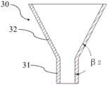
在本实用新型的一些实施例中,如图5所示,输送器100还包括装载器30,装载器30安装于外鞘导管13的远端。如图6所示,装载器30包括连接部31和装载部32,连接部31用于与外鞘导管13连接,装载部32形成有由远端到近端渐缩的内腔。In some embodiments of the present invention, as shown in FIG. 5 , the
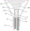
如图9至图14所示,在假体瓣膜200进行装鞘进入外鞘导管13内腔的过程中,首先将装载器30与外鞘导管13相连,接着操作手柄组件20使外鞘导管13和压缩导管12朝向近端一定,使连接导管11的连接头111从外鞘导管13和压缩导管12的远端露出;接着将假体瓣膜200连接至连接导管11的连接头111上,再操作手柄组件20使压缩导管12朝向远端移动,初步压缩连接支架213;然后操作手柄组件20使外鞘导管13朝向远端移动,逐步将压缩导管12收入到外鞘导管13的内腔中,在此过程中,外鞘导管13的最远端边缘部分直接与假体瓣膜200的主体支架212的覆膜部分接触,而不是与覆膜和主体支架的交界处a接触,主体支架近端覆膜部分“翻边”或堆积,导致假体瓣膜装载力过大或发生变形。当连接支架213完全收入在外鞘导管13内时,进一步使外鞘导管13向远端方向运动,假体瓣膜200的主体支架212和裙边支架211将会受到装载器30的束缚作用,均匀挤压收缩。待将假体瓣膜200完全收入输送器100的外鞘导管13内腔后,可将装载器30从外鞘导管13上拆卸,完成假体瓣膜200的装载。As shown in FIGS. 9 to 14 , when the
由于主体支架212和裙边支架211上均具有覆膜220,在尽量降低外鞘导管13尺寸的前提下,假体瓣膜200压缩后的横截面积与外鞘导管13的截面积相当,径向支撑力大。若直接通过外鞘导管13的运动来装载假体瓣膜200,而无其它装置辅助,假体瓣膜200的生物瓣膜可能会发生不规则的折叠或挤压变形,最终可能导致假体瓣膜200在心脏内释放后难以按照预期进行工作,危害病人生命健康。另外,不借用其它辅助装置,直接通过外鞘导管的运动来装载假体瓣膜还可能因为瓣膜径向力过大将外鞘导管挤压破裂。在本实施例中,外鞘导管13的远端装有装载器30,在假体瓣膜200进行预压缩过程中,装载器30对其可起一定支撑作用,避免假体瓣膜200的连接支架213在收入压缩导管12的管腔中发生扭曲变形。接着在装载假体瓣膜200的主体支架212和裙边支架211时,由于装载器30的约束作用下,假体瓣膜200的生物瓣在装载的过程中会逐渐的被缩小且过渡顺畅,无不规则折叠,可避免发生不规则挤压变形。此外,由于装载器30在假体瓣膜200的外部支撑,以及提前让外鞘导管13远端外侧的假体瓣膜200发生规则的形变逐渐缩小,假体瓣膜200不会在外鞘导管13的开口处发生突然的形变,导致假体瓣膜200收入外鞘导管13中力突然增大,造成假体瓣膜装载困难、外鞘导管远端开口破损或损伤生物瓣。Since both the
进一步地,如图7所示,装载部32的内腔为圆台形腔体,并且,装载部32与连接部31的夹角β2大于假体瓣膜200在自然展开状态下的主体支架212与裙边支架211间的夹角β1。由此,可以保证装载器30对裙边支架211和主体支架212的束缚作用。Further, as shown in FIG. 7 , the inner cavity of the
进一步地,装载部32的内腔在输送器100的轴向上的长度大于自然展开状态下主体支架212与裙边支架211在假体瓣膜200的轴向上的长度之和,以便于假体瓣膜200的连接支架213收入连接导管11时主体支架212和裙边支架211均可以受到装载器30的装载部32的束缚作用,从而使主体支架212和裙边支架211均匀挤压收缩。Further, the length of the inner cavity of the
进一步地,装载器30的材质为高强度材料,从而为假体瓣膜200的装置提供足够的支撑力。优选低摩擦系数的的材料和透明材料,如PTFE等,可以随时观察假体瓣膜200的形状以确定其压缩形状;或者选择表面涂覆/喷涂有润滑层的金属或高分子材料,可以减少装载器30对假体瓣膜200的摩擦或剐蹭。Further, the material of the
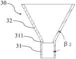
进一步地,装载器30的连接部31为直管状结构,其与外鞘导管13紧密配合,即连接部31的内径与外鞘导管13的外径相等。优选地,装载器30内表面还包括凸台结构311(如图8所示),凸台结构311连接连接部31的内表面和装载部32的内表面。也就是说,装载部32的内表面与连接部31的内表面不是光滑连接,而是形成一个台阶。具体地,凸台结构311的内径与外鞘导管13的内径一致,凸台结构311的轴向长度为1mm至5mm。针对个别假体瓣膜200尺寸较大或结构较复杂(例如含有倒刺结构)的情况,可在装载假体瓣膜200的过程中,保护外鞘导管13最远端的端部,避免假体瓣膜200的支架刮破外鞘导管13的远端端部从而造成缺口,降低外鞘导管13的端部刮伤组织的风险。Further, the
在本实用新型的一些实施例中,输送器100还包括设置于外鞘导管13的远端的显影件(例如显影环)40(见图2),用于在DSA成像设备下指示外鞘导管13在心脏内的具体位置。进一步地,显影件40的材料可以为金属铂、钽或钨。另外,显影件40的远端具有柔性端部,从而可以避免划伤组织。In some embodiments of the present invention, the
本实用新型第二方面的实施例提出了一种假体瓣膜输送系统,其包括假体瓣膜200和上述任一实施例中的输送器100。其中,假体瓣膜200包括支架210、覆膜220和生物瓣膜,支架210包括由远端到近端依次连接的裙边支架211、主体支架212和连接支架213,覆膜220固定在裙边支架211和主体支架212上,生物瓣膜位于主体支架212的内侧,连接支架213能够以可拆卸的方式安装于连接导管11的远端。An embodiment of the second aspect of the present invention provides a prosthetic valve delivery system, which includes a
根据本实用新型实施例的假体瓣膜输送系统,由于具有根据本实用新型第一方面的实施例的输送器100,因此,本实用新型实施例的输送系统具有上述输送器100的一切技术效果,在此不再进行赘述。Since the prosthetic valve delivery system according to the embodiment of the present invention has the
以上所述,仅为本实用新型较佳的具体实施方式,但本实用新型的保护范围并不局限于此,任何熟悉本技术领域的技术人员在本实用新型揭露的技术范围内,可轻易想到的变化或替换,都应涵盖在本实用新型的保护范围之内。因此,本实用新型的保护范围应以所述权利要求的保护范围为准。The above are only the preferred specific embodiments of the present invention, but the protection scope of the present invention is not limited to this. The changes or replacements should be covered within the protection scope of the present invention. Therefore, the protection scope of the present invention should be based on the protection scope of the claims.
Claims (10)
Translated fromChinesePriority Applications (1)
| Application Number | Priority Date | Filing Date | Title |
|---|---|---|---|
| CN201922142994.1UCN211934440U (en) | 2019-12-03 | 2019-12-03 | Conveyor and conveying system |
Applications Claiming Priority (1)
| Application Number | Priority Date | Filing Date | Title |
|---|---|---|---|
| CN201922142994.1UCN211934440U (en) | 2019-12-03 | 2019-12-03 | Conveyor and conveying system |
Publications (1)
| Publication Number | Publication Date |
|---|---|
| CN211934440Utrue CN211934440U (en) | 2020-11-17 |
Family
ID=73176675
Family Applications (1)
| Application Number | Title | Priority Date | Filing Date |
|---|---|---|---|
| CN201922142994.1UActiveCN211934440U (en) | 2019-12-03 | 2019-12-03 | Conveyor and conveying system |
Country Status (1)
| Country | Link |
|---|---|
| CN (1) | CN211934440U (en) |
- 2019
- 2019-12-03CNCN201922142994.1Upatent/CN211934440U/enactiveActive
Similar Documents
| Publication | Publication Date | Title |
|---|---|---|
| US11666438B2 (en) | Transcatheter prosthetic heart valve delivery system with recapturing feature and method | |
| JP6854356B2 (en) | Systems that deliver implantable medical devices and systems that implant heart valves | |
| US10105223B2 (en) | Transcatheter prosthetic heart valve delivery system with recapturing feature | |
| JP6356192B2 (en) | Prosthetic heart valve delivery device | |
| EP2699200B1 (en) | Transcatheter prosthetic heart valve delivery system with flush port | |
| CN107438415B (en) | Transcatheter prosthetic heart valve delivery systems and methods | |
| EP2898857B1 (en) | Implant conveying system | |
| US8876878B2 (en) | Attachment mechanism for stent release | |
| US9381083B2 (en) | Profile altering tip for a delivery system | |
| CN110897763B (en) | Medical instrument conveying device | |
| CN109984867B (en) | Medical instrument conveying device | |
| AU2011238743A1 (en) | Transcatheter heart valve delivery system with reduced area moment of inertia | |
| CN109984866B (en) | Medical Device Delivery Devices | |
| CN110868965A (en) | Medical device with sealing assembly | |
| CN109984869B (en) | Heart valve prosthesis delivery device | |
| CN117481871A (en) | Prosthetic valve conveying device and system | |
| WO2020029979A1 (en) | Implant loading apparatus | |
| WO2022262110A1 (en) | Implant delivery apparatus and implant delivery system | |
| CN211934440U (en) | Conveyor and conveying system | |
| CN222383431U (en) | Prosthetic valve conveying device and system | |
| CN223009319U (en) | Transcatheter aortic dry valve delivery system | |
| CN209595972U (en) | Conveying device and conveying system | |
| WO2021135351A1 (en) | Implant body delivery system and inner tube thereof |
Legal Events
| Date | Code | Title | Description |
|---|---|---|---|
| GR01 | Patent grant | ||
| GR01 | Patent grant | ||
| TR01 | Transfer of patent right | ||
| TR01 | Transfer of patent right | Effective date of registration:20231228 Address after:518000 1604, Xianjian technology building, No. 22, Keji South 12th Road, gaoxinyuan community, Yuehai street, Nanshan District, Shenzhen, Guangdong Province Patentee after:Shenzhen Jianxin Medical Technology Co.,Ltd. Address before:518000 1st-5th Floor of Saiba Research Building, Langshan Second Road, North District of Nanshan High-tech Industrial Park, Shenzhen City, Guangdong Province Patentee before:LIFETECH SCIENTIFIC (SHENZHEN) Co.,Ltd. |