CN211796756U - CT-guided puncture combined orienting device - Google Patents
CT-guided puncture combined orienting deviceDownload PDFInfo
- Publication number
- CN211796756U CN211796756UCN201922259364.2UCN201922259364UCN211796756UCN 211796756 UCN211796756 UCN 211796756UCN 201922259364 UCN201922259364 UCN 201922259364UCN 211796756 UCN211796756 UCN 211796756U
- Authority
- CN
- China
- Prior art keywords
- fixedly installed
- rod
- base
- hydraulic
- hydraulic lifting
- Prior art date
- Legal status (The legal status is an assumption and is not a legal conclusion. Google has not performed a legal analysis and makes no representation as to the accuracy of the status listed.)
- Expired - Fee Related
Links
- 230000005484gravityEffects0.000claimsdescription8
- 230000002035prolonged effectEffects0.000abstractdescription2
- 238000010586diagramMethods0.000description4
- 238000003780insertionMethods0.000description4
- 230000037431insertionEffects0.000description4
- 238000000034methodMethods0.000description4
- 238000002591computed tomographyMethods0.000description3
- 230000000694effectsEffects0.000description2
- 238000012986modificationMethods0.000description1
- 230000004048modificationEffects0.000description1
- 230000005855radiationEffects0.000description1
Images

Landscapes
- Apparatus For Radiation Diagnosis (AREA)
Abstract
Description
Translated fromChinese技术领域technical field
本实用新型涉及医疗器械技术领域,具体为一种CT引导穿刺组合定向装置。The utility model relates to the technical field of medical instruments, in particular to a CT-guided puncture combined orientation device.
背景技术Background technique
采用CT引导下的介入技术,定位的精度高,安全性好,目前已经成为一项非常有价值的检查与治疗的方法,采用CT引导进行的穿刺,其体内靶点、体表穿刺点、穿刺的角度和深度,均可以由CT扫描图片精确定位和测量,但在实际的操作过程中,穿刺时进针方向的把握是右一定难度的,大部分情况下药经过多次试穿刺才能确定正确的方向,并因此造成手术的时间延长,辐射的剂量增大,也因此会增大了医务人员的劳动强度,同时也增大了患者的痛苦,现有的技术中,引导穿刺角度及深度可以由CT扫描图片精确定位与测量,但是穿刺时进针方向的把握却有一定的难度,穿刺定位装置在使用时不方便,而且定位不准确,操作复杂,浪费时间,部分情况下要经过多次试穿后才能找到正确的方向,造成手术时间长、并发症较多、患者痛苦大等问题,影响到了治疗的效果。The CT-guided interventional technology has high positioning accuracy and good safety, and has now become a very valuable method for examination and treatment. The angle and depth of the needle can be accurately located and measured by CT scan pictures, but in the actual operation process, it is difficult to grasp the direction of needle insertion during puncture. Therefore, the operation time is prolonged, and the radiation dose is increased, which will increase the labor intensity of medical staff and increase the pain of patients. In the existing technology, the guide puncture angle and depth can be determined by The CT scan images can be accurately positioned and measured, but it is difficult to grasp the direction of needle insertion during puncture. The puncture positioning device is inconvenient to use, and the positioning is not accurate, the operation is complicated, and time is wasted. In some cases, multiple trials are required. The correct direction can only be found after wearing it, resulting in problems such as long operation time, many complications, and great pain for patients, which affects the effect of treatment.
实用新型内容Utility model content
本部分的目的在于概述本实用新型的实施方式的一些方面以及简要介绍一些较佳实施方式。在本部分以及本申请的说明书摘要和实用新型名称中可能会做些简化或省略以避免使本部分、说明书摘要和实用新型名称的目的模糊,而这种简化或省略不能用于限制本实用新型的范围。The purpose of this section is to outline some aspects of embodiments of the invention and to briefly introduce some preferred embodiments. Some simplifications or omissions may be made in this part and the abstract of the specification and the title of the utility model of this application to avoid obscuring the purpose of this part, the abstract of the specification and the title of the utility model, and such simplification or omission cannot be used to limit the utility model range.
鉴于上述和/或现有医疗器械中存在的问题,提出了本实用新型。In view of the above and/or problems existing in existing medical devices, the present utility model is proposed.
因此,本实用新型的目的是提供一种CT引导穿刺组合定向装置,能够通过引导穿刺定向激光灯根据交叉投影拟合原理,进行穿刺,同时能调节穿刺定向激光灯的高度和角度,提高了装置的实用性,便于查找定位的准确性,且加入固定装置,提高装置的稳定性,延长装置的使用寿命。Therefore, the purpose of the present utility model is to provide a combined orientation device for CT guided puncture, which can guide the puncture directional laser light to perform puncture according to the principle of cross-projection fitting, and at the same time can adjust the height and angle of the puncture directional laser light. The practicability of the device is convenient for finding the accuracy of positioning, and a fixing device is added to improve the stability of the device and prolong the service life of the device.
为解决上述技术问题,根据本实用新型的一个方面,本实用新型提供了如下技术方案:In order to solve the above-mentioned technical problems, according to one aspect of the present utility model, the utility model provides the following technical solutions:
一种CT引导穿刺组合定向装置,包括底座、液压升降杆和液压伸缩杆,所述底座的顶部固定安装液压升降杆,所述液压升降杆与底座的顶部通过螺栓螺纹连接,所述液压升降杆的侧壁上设置有滑槽,所述滑槽上设置有滑块,所述滑块的顶部固定安装有第一连接杆,所述第一连接杆的右侧壁固定安装有横向激光灯,所述液压伸缩杆固定安装在液压升降杆的顶部,所述液压伸缩杆的侧壁与液压升降杆的顶部通过螺栓螺纹连接,所述液压伸缩杆的顶部固定安装有第二连接杆,所述第二连接杆的底部固定安装有纵向激光灯。A CT-guided puncture combined orientation device, comprising a base, a hydraulic lifting rod and a hydraulic telescopic rod, a hydraulic lifting rod is fixedly installed on the top of the base, the hydraulic lifting rod and the top of the base are threadedly connected by bolts, and the hydraulic lifting rod A chute is set on the side wall of the slide slot, a slider is set on the chute, a first connecting rod is fixedly installed on the top of the slider, and a horizontal laser light is fixedly installed on the right side wall of the first connecting rod, The hydraulic telescopic rod is fixedly installed on the top of the hydraulic lifting rod, the side wall of the hydraulic telescopic rod and the top of the hydraulic lifting rod are threadedly connected by bolts, and a second connecting rod is fixedly installed on the top of the hydraulic telescopic rod. A longitudinal laser light is fixedly installed on the bottom of the second connecting rod.
作为本实用新型所述的一种CT引导穿刺组合定向装置的一种优选方案,其中:所述液压升降杆和液压伸缩杆的侧壁上固定安装有尺码表,所述尺码表与液压升降杆和液压伸缩杆的侧壁胶接。As a preferred solution of the CT-guided puncture combined orientation device of the present invention, wherein: a size chart is fixedly installed on the side walls of the hydraulic lifting rod and the hydraulic telescopic rod, and the size chart is connected to the hydraulic lifting rod. It is glued to the side wall of the hydraulic telescopic rod.
作为本实用新型所述的一种CT引导穿刺组合定向装置的一种优选方案,其中:所述底座的底部固定安装有支撑架,所述支撑架与底座的底部通过螺栓螺纹连接,所述支撑架的底部固定安装有滑轮,所述支撑架的左侧壁固定安装有轮刹,所述轮刹与支撑架的左侧壁通过螺栓螺纹连接。As a preferred solution of the CT-guided puncture combined orientation device according to the present invention, a support frame is fixedly installed at the bottom of the base, and the support frame and the bottom of the base are connected by bolts and threads. A pulley is fixedly installed on the bottom of the frame, a wheel brake is fixedly installed on the left side wall of the support frame, and the wheel brake is connected with the left side wall of the support frame by bolts and threads.
作为本实用新型所述的一种CT引导穿刺组合定向装置的一种优选方案,其中:所述底座的底部固定安装有重心盘,所述重心盘与底座的底部通过螺栓螺纹连接。As a preferred solution of the CT-guided puncture combined orientation device of the present invention, a center of gravity disk is fixedly installed on the bottom of the base, and the center of gravity disk and the bottom of the base are threadedly connected by bolts.
作为本实用新型所述的一种CT引导穿刺组合定向装置的一种优选方案,其中:所述底座的顶部固定安装有控制器,所述控制器与底座的顶部通过螺栓螺纹连接,所述液压升降杆和液压伸缩杆与控制器通过连接线连接。As a preferred solution of the CT-guided puncture combined orientation device of the present invention, a controller is fixedly installed on the top of the base, and the controller and the top of the base are threadedly connected by bolts, and the hydraulic pressure The lifting rod and the hydraulic telescopic rod are connected with the controller through the connecting line.
与现有技术相比:现有的技术中,引导穿刺角度及深度可以由CT扫描图片精确定位与测量,但是穿刺时进针方向的把握却有一定的难度,穿刺定位装置在使用时不方便,而且定位不准确,操作复杂,浪费时间,部分情况下要经过多次试穿后才能找到正确的方向,造成手术时间长、并发症较多、患者痛苦大等问题,影响到了治疗的效果,本申请文中,能够通过引导穿刺定向激光灯根据交叉投影拟合原理,进行穿刺,同时能调节穿刺定向激光灯的高度和角度,提高了装置的实用性,便于查找定位的准确性,且加入固定装置,提高装置的稳定性,延长装置的使用寿命。Compared with the prior art: in the prior art, the guide puncture angle and depth can be accurately positioned and measured by CT scan pictures, but it is difficult to grasp the needle insertion direction during puncture, and the puncture positioning device is inconvenient to use. , and the positioning is inaccurate, the operation is complicated, and time is wasted. In some cases, the correct direction can only be found after several tries, resulting in long operation time, more complications, and great pain for patients, which affects the effect of treatment. In this application, puncturing can be performed by guiding the puncture directional laser light according to the principle of cross-projection fitting, and at the same time, the height and angle of the puncture directional laser light can be adjusted, which improves the practicability of the device, facilitates the accuracy of search and positioning, and adds a fixed The device can improve the stability of the device and prolong the service life of the device.
附图说明Description of drawings
为了更清楚地说明本实用新型实施方式的技术方案,下面将结合附图和详细实施方式对本实用新型进行详细说明,显而易见地,下面描述中的附图仅仅是本实用新型的一些实施方式,对于本领域普通技术人员来讲,在不付出创造性劳动性的前提下,还可以根据这些附图获得其它的附图。其中:In order to more clearly illustrate the technical solutions of the embodiments of the present invention, the present invention will be described in detail below with reference to the accompanying drawings and detailed embodiments. Obviously, the accompanying drawings in the following description are only some embodiments of the present invention. For those of ordinary skill in the art, other drawings can also be obtained based on these drawings without any creative effort. in:
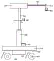
图1为本实用新型一种CT引导穿刺组合定向装置的结构示意图;1 is a schematic structural diagram of a CT-guided puncture combined orientation device of the present invention;
图2为本实用新型一种CT引导穿刺组合定向装置的滑槽示意图。FIG. 2 is a schematic diagram of a chute of a CT-guided puncture combined orientation device of the present invention.
图中:100底座、200液压升降杆、210滑槽、220滑块、230第一连接杆、240横向激光灯、300液压伸缩杆、310第二连接杆、320纵向激光灯、400尺码表、500支撑架、510滑轮、520轮刹、600重心盘、700控制器。In the picture: 100 base, 200 hydraulic lift rod, 210 chute, 220 slider, 230 first connecting rod, 240 horizontal laser light, 300 hydraulic telescopic rod, 310 second connecting rod, 320 vertical laser light, 400 size table, 500 support frame, 510 pulley, 520 wheel brake, 600 center of gravity disc, 700 controller.
具体实施方式Detailed ways
为使本实用新型的上述目的、特征和优点能够更加明显易懂,下面结合附图对本实用新型的具体实施方式做详细的说明。In order to make the above objects, features and advantages of the present utility model more clearly understood, the specific embodiments of the present utility model are described in detail below with reference to the accompanying drawings.
在下面的描述中阐述了很多具体细节以便于充分理解本实用新型,但是本实用新型还可以采用其他不同于在此描述的其它方式来实施,本领域技术人员可以在不违背本实用新型内涵的情况下做类似推广,因此本实用新型不受下面公开的具体实施方式的限制。In the following description, many specific details are set forth in order to fully understand the present utility model, but the present utility model can also be implemented in other ways different from those described herein, and those skilled in the art can do so without departing from the connotation of the present utility model. Therefore, the present invention is not limited by the specific embodiments disclosed below.
其次,本实用新型结合示意图进行详细描述,在详述本实用新型实施方式时,为便于说明,表示器件结构的剖面图会不依一般比例作局部放大,而且所述示意图只是示例,其在此不应限制本实用新型保护的范围。此外,在实际制作中应包含长度、宽度及深度的三维空间尺寸。Next, the present invention is described in detail with reference to the schematic diagrams. When describing the embodiments of the present utility model in detail, for the convenience of explanation, the cross-sectional views showing the device structure will not be partially enlarged according to the general scale, and the schematic diagrams are only examples, which are not described here. The scope of protection of the present invention should be limited. In addition, the three-dimensional spatial dimensions of length, width and depth should be included in the actual production.
为使本实用新型的目的、技术方案和优点更加清楚,下面将结合附图对本实用新型的实施方式作进一步地详细描述。In order to make the objectives, technical solutions and advantages of the present utility model clearer, the embodiments of the present utility model will be further described in detail below with reference to the accompanying drawings.
本实用新型提供一种CT引导穿刺组合定向装置,请参阅图1-图2,包括底座100、液压升降杆200和液压伸缩杆300,底座100的顶部固定安装液压升降杆200,液压升降杆200与底座100的顶部通过螺栓螺纹连接,液压升降杆200的侧壁上设置有滑槽210,滑槽210上设置有滑块220,滑块220的顶部固定安装有第一连接杆230,第一连接杆230的右侧壁固定安装有横向激光灯240,液压伸缩杆300固定安装在液压升降杆200的顶部,液压伸缩杆300的侧壁与液压升降杆200的顶部通过螺栓螺纹连接,液压伸缩杆300的顶部固定安装有第二连接杆310,第二连接杆310的底部固定安装有纵向激光灯320,具体的,底座100用于放置装置,提高装置的稳定性,所述液压升降杆200用于调节液压伸缩杆300上纵向激光灯320的高度,滑槽210用于上下移动横向激光灯240的高度,滑块220用于连接连接杆,连接杆用于固定横向激光灯240,液压伸缩杆300用于调节纵向激光灯320的角度,横向激光灯240与纵向激光灯320的交叉定位,方便医生找到正确的进针方向,提高了医生的工作效率,降低了工作难度。The utility model provides a CT-guided puncture combined orientation device, please refer to FIG. 1 to FIG. 2 , which includes a
请参阅图1,液压升降杆200和液压伸缩杆300的侧壁上固定安装有尺码表400,尺码表400与液压升降杆200和液压伸缩杆300的侧壁胶接,具体的,尺码表400用于衡量激光灯的距离值,方便医生观察,提高了装置的准确性。Please refer to FIG. 1 , a size table 400 is fixedly installed on the side walls of the
请再次参阅图1,底座100的底部固定安装有支撑架500,支撑架500与底座100的底部通过螺栓螺纹连接,支撑架500的底部固定安装有滑轮510,支撑架500的左侧壁固定安装有轮刹520,轮刹520与支撑架500的左侧壁通过螺栓螺纹连接,具体的,支撑架500提高了装置的稳定性,滑轮510用于方便移动装置,轮刹520用于固定滑轮510,提高了装置的实用性。Please refer to FIG. 1 again, a
请再次参阅图1,底座100的底部固定安装有重心盘600,重心盘600与底座100的底部通过螺栓螺纹连接,具体的,重心盘600用于固定装置,提高了装置的稳定性,避免滑到,延长装置的使用寿命。Please refer to FIG. 1 again, the bottom of the
请再次参阅图1,底座100的顶部固定安装有控制器700,控制器700与底座100的顶部通过螺栓螺纹连接,液压升降杆200和液压伸缩杆300与控制器700通过连接线连接,具体的控制器700用于控制液压升降杆200和液压伸缩杆300,方便操作。Please refer to FIG. 1 again, a
在具体使用过程中,使用者根据需求,使用控制器700操作液压升降杆200和液压伸缩杆300,调整纵向激光灯320的角度和高度,使用滑槽210上的滑块220调整横向激光灯240的高度,纵向激光灯320和横向激光灯240的交叉定向点,观察尺码表400进行测量,使用者确定好定向点,使用穿刺针穿刺。In the specific use process, the user uses the
虽然在上文中已经参考实施方式对本实用新型进行了描述,然而在不脱离本实用新型的范围的情况下,可以对其进行各种改进并且可以用等效物替换其中的部件。尤其是,只要不存在结构冲突,本实用新型所披露的实施方式中的各项特征均可通过任意方式相互结合起来使用,在本说明书中未对这些组合的情况进行穷举性的描述仅仅是出于省略篇幅和节约资源的考虑。因此,本实用新型并不局限于文中公开的特定实施方式,而是包括落入权利要求的范围内的所有技术方案。Although the present invention has been described above with reference to the embodiments, various modifications may be made and equivalents may be substituted for parts thereof without departing from the scope of the invention. In particular, as long as there is no structural conflict, the various features in the disclosed embodiments of the present invention can be combined with each other in any way, and the description of these combinations is not exhaustive in this specification. For the sake of omitting space and saving resources. Therefore, the present invention is not limited to the specific embodiments disclosed herein, but includes all technical solutions falling within the scope of the claims.
Claims (5)
Translated fromChinesePriority Applications (1)
| Application Number | Priority Date | Filing Date | Title |
|---|---|---|---|
| CN201922259364.2UCN211796756U (en) | 2019-12-16 | 2019-12-16 | CT-guided puncture combined orienting device |
Applications Claiming Priority (1)
| Application Number | Priority Date | Filing Date | Title |
|---|---|---|---|
| CN201922259364.2UCN211796756U (en) | 2019-12-16 | 2019-12-16 | CT-guided puncture combined orienting device |
Publications (1)
| Publication Number | Publication Date |
|---|---|
| CN211796756Utrue CN211796756U (en) | 2020-10-30 |
Family
ID=73140791
Family Applications (1)
| Application Number | Title | Priority Date | Filing Date |
|---|---|---|---|
| CN201922259364.2UExpired - Fee RelatedCN211796756U (en) | 2019-12-16 | 2019-12-16 | CT-guided puncture combined orienting device |
Country Status (1)
| Country | Link |
|---|---|
| CN (1) | CN211796756U (en) |
Cited By (3)
| Publication number | Priority date | Publication date | Assignee | Title |
|---|---|---|---|---|
| CN113262023A (en)* | 2021-05-18 | 2021-08-17 | 陈志明 | Supplementary laser positioning device that uses of anesthesia puncture in canalis spinalis |
| CN114010283A (en)* | 2021-11-17 | 2022-02-08 | 中国人民解放军联勤保障部队第九二〇医院 | Laser positioning device for percutaneous lung cross-laminar puncture under CT guidance |
| CN114343805A (en)* | 2022-03-01 | 2022-04-15 | 吉林大学 | Puncture guiding device for prenatal diagnosis and nursing |
- 2019
- 2019-12-16CNCN201922259364.2Upatent/CN211796756U/ennot_activeExpired - Fee Related
Cited By (5)
| Publication number | Priority date | Publication date | Assignee | Title |
|---|---|---|---|---|
| CN113262023A (en)* | 2021-05-18 | 2021-08-17 | 陈志明 | Supplementary laser positioning device that uses of anesthesia puncture in canalis spinalis |
| CN114010283A (en)* | 2021-11-17 | 2022-02-08 | 中国人民解放军联勤保障部队第九二〇医院 | Laser positioning device for percutaneous lung cross-laminar puncture under CT guidance |
| CN114010283B (en)* | 2021-11-17 | 2025-01-28 | 中国人民解放军联勤保障部队第九二〇医院 | A laser positioning device for CT-guided percutaneous trans-laminar pulmonary puncture |
| CN114343805A (en)* | 2022-03-01 | 2022-04-15 | 吉林大学 | Puncture guiding device for prenatal diagnosis and nursing |
| CN114343805B (en)* | 2022-03-01 | 2023-09-01 | 吉林大学 | Puncture guiding device for prenatal diagnosis and nursing |
Similar Documents
| Publication | Publication Date | Title |
|---|---|---|
| CN211796756U (en) | CT-guided puncture combined orienting device | |
| CN207621621U (en) | A kind of computer display | |
| CN102920513A (en) | Augmented reality system experiment platform based on projector | |
| WO2023000773A1 (en) | Near infrared-based brain injury detection method and detection apparatus | |
| CN204133607U (en) | To perform the operation special shooting support | |
| CN114532705A (en) | Clinical medical diagnosis picture comparison library and use method thereof | |
| CN209076730U (en) | A kind of medical height-adjustable rack for test tube | |
| CN216754604U (en) | Clinical rescue auxiliary assembly of intracardiac branch of academic or vocational study | |
| CN207137157U (en) | A kind of radiotherapy overturns bed | |
| CN216257394U (en) | Comprehensive placement equipment for medical instruments | |
| CN211355612U (en) | Medical clinical tumour sampler | |
| CN205198161U (en) | Head -mounted locater | |
| CN204839564U (en) | Take laser adjusting device of damping action | |
| CN215192098U (en) | CT-guided puncture stereotaxic instrument | |
| CN221665770U (en) | Three-dimensional measuring device for engineering cost | |
| CN220513205U (en) | Measuring device with height-adjustable drainage tube | |
| CN211409286U (en) | Three-dimensional angle leading truck of CT puncture | |
| CN223095769U (en) | Operating table is with placing platform | |
| CN204971497U (en) | CT accurate positioner that punctures | |
| CN222461005U (en) | Light field uniformity testing device of lighting system | |
| CN211381420U (en) | Movable X-ray examination support | |
| CN211205224U (en) | Mechanical part size mapping device | |
| CN221858112U (en) | Drawing auxiliary device for archaeological measurement | |
| CN219847112U (en) | Combined stretcher | |
| CN213640901U (en) | Head-adjustable X-ray machine |
Legal Events
| Date | Code | Title | Description |
|---|---|---|---|
| GR01 | Patent grant | ||
| GR01 | Patent grant | ||
| CF01 | Termination of patent right due to non-payment of annual fee | ||
| CF01 | Termination of patent right due to non-payment of annual fee | Granted publication date:20201030 |