CN211794314U - Atomizer and electronic cigarette - Google Patents
Atomizer and electronic cigaretteDownload PDFInfo
- Publication number
- CN211794314U CN211794314UCN201921060489.6UCN201921060489UCN211794314UCN 211794314 UCN211794314 UCN 211794314UCN 201921060489 UCN201921060489 UCN 201921060489UCN 211794314 UCN211794314 UCN 211794314U
- Authority
- CN
- China
- Prior art keywords
- liquid
- upper cover
- liquid injection
- annotate
- cover
- Prior art date
- Legal status (The legal status is an assumption and is not a legal conclusion. Google has not performed a legal analysis and makes no representation as to the accuracy of the status listed.)
- Active
Links
Images


Landscapes
- Containers And Packaging Bodies Having A Special Means To Remove Contents (AREA)
Abstract
Translated fromChinese
Description
Translated fromChinese技术领域technical field
本实用新型涉及模拟吸烟技术领域,特别地,涉及一种雾化器及电子烟。The utility model relates to the technical field of simulated smoking, in particular to an atomizer and an electronic cigarette.
背景技术Background technique
电子烟又名为虚拟香烟、电子雾化器、电子雪茄烟,有着与香烟一样的外观,与香烟近似的味道,主要是用于模拟吸烟的感觉,以供戒烟或香烟替代使用。Electronic cigarettes, also known as virtual cigarettes, electronic atomizers, and electronic cigars, have the same appearance as cigarettes and a similar taste to cigarettes. They are mainly used to simulate the feeling of smoking for quitting smoking or replacing cigarettes.
目前,推盖式雾化器凭借其注液操作方便的优势越来越受到用户的青睐,使用时,用户只需要平推注液盖,从而将设置在上盖上的注液口打开即可进行注液操作。但是,市面上仅有的推盖式雾化器,不仅结构复杂,且缺乏一定的限位结构,用户欲注液而平推注液盖时,极易发生注液盖与上盖相脱离的情况,进而降低了用户的使用体验。At present, the push-cap nebulizer is more and more favored by users because of its convenient liquid injection operation. When using it, the user only needs to push the liquid injection cover flatly, so as to open the liquid injection port set on the upper cover. Carry out the injection operation. However, the only push-cap atomizer on the market is not only complicated in structure, but also lacks a certain limit structure. When the user wants to inject liquid and push the liquid-injection cap, the liquid-injection cap is easily separated from the upper cover. situation, thereby reducing the user experience.
实用新型内容Utility model content
基于此,有必要提供一种可有效防止注液时注液盖与上盖相脱离的雾化器;Based on this, it is necessary to provide an atomizer that can effectively prevent the liquid injection cover from separating from the upper cover during liquid injection;
还有必要提供一种带有该雾化器的电子烟。It is also necessary to provide an electronic cigarette with the atomizer.
本实用新型解决其技术问题所采用的技术方案是:一种雾化器,包括上盖组件,所述上盖组件包括具有注液口的上盖、注液盖和限位件,所述注液盖可相对所述上盖滑动,滑动所述注液盖可关闭或打开所述注液口,所述上盖上面向所述注液盖的端面设置有滑槽,所述注液盖可滑动地卡嵌于所述滑槽内,当滑动所述注液盖至所述注液口被打开时,所述注液盖与所述限位件相抵持从而限制所述注液盖与所述滑槽相脱离。The technical solution adopted by the utility model to solve the technical problem is as follows: an atomizer, comprising an upper cover assembly, the upper cover assembly includes an upper cover with a liquid injection port, a liquid injection cover and a limiter, the injection The liquid cover can slide relative to the upper cover, and the liquid injection cover can be slid to close or open the liquid injection port. It is slidably embedded in the chute, and when the liquid injection cover is slid until the liquid injection port is opened, the liquid injection cover is abutted against the limiting member to restrict the liquid injection cover and the The chute is disengaged.
进一步地,所述上盖上面向所述注液盖的端面开设有凹槽,所述注液口位于所述凹槽的一侧,所述凹槽上靠近所述注液口的一端的两个相对侧壁上朝相对方向凸设有两个凸缘,所述滑槽由两个所述凸缘与所述凹槽的槽壁围设的空间构成,所述注液盖上凸设有与所述滑槽相配合的滑块。Further, a groove is formed on the end face of the upper cover facing the liquid injection cover, the liquid injection port is located on one side of the groove, and the two grooves on the groove close to one end of the liquid injection port are provided with grooves. Two flanges protrude in opposite directions on the opposite side walls, the chute is formed by the space enclosed by the two flanges and the groove wall of the groove, and the liquid injection cover is protruded with A slider matched with the chute.
进一步地,所述凹槽的内腔相对所述滑槽远离所述注液口的部分形成容置槽,所述限位件至少部分位于所述容置槽内,当所述注液口打开时,所述滑块与所述限位件相抵持。Further, the inner cavity of the groove forms a accommodating groove relative to the part of the chute that is far from the liquid injection port, and the limiting member is at least partially located in the accommodating groove, when the liquid injection port is opened When the slider is pressed against the limiting member.
进一步地,所述上盖上远离所述注液盖的端面开设有安装槽,所述安装槽与所述凹槽的容置槽相连通,所述限位件安装在所述安装槽内,且所述限位件部分伸入至所述容置槽内。Further, an installation groove is formed on the end face of the upper cover away from the liquid injection cover, the installation groove is communicated with the accommodating groove of the groove, and the limiting member is installed in the installation groove, and the limiting member partially extends into the accommodating groove.
进一步地,所述上盖的侧壁开设有安装槽,所述安装槽与所述容置槽相连通,所述限位件安装在所述安装槽内,且所述限位件部分伸入至所述容置槽内。Further, the side wall of the upper cover is provided with a mounting groove, the mounting groove is communicated with the accommodating groove, the limiting member is installed in the mounting groove, and the limiting member partially protrudes into the mounting groove. into the accommodating groove.
进一步地,所述滑槽是由凸设在所述上盖上面向所述注液盖的端面且相对设置的两个限位块构成,所述限位件安装在所述上盖上面向所述注液盖的端面且位于所述注液盖的移动路径中,所述限位件位于所述滑槽远离所述注液口的一侧。Further, the chute is composed of two limit blocks that are protruded on the upper cover and face the end face of the liquid injection cover and are oppositely arranged, and the limit pieces are installed on the upper cover and face the The end face of the liquid injection cover is located in the moving path of the liquid injection cover, and the limiting member is located on the side of the chute away from the liquid injection port.
进一步地,所述上盖上还设置有出烟口,所述注液盖上设置有通气口,所述注液口和所述出烟口依次设置在所述注液盖相对上盖由使用位置移动至所述注液位置的移动路径中,当所述注液盖位于所述使用位置时,所述注液口被关闭,所述通气口与所述出烟口对位连通,当所述注液盖位于所述注液位置时,所述注液口被打开,所述注液盖与所述限位件相抵持。Further, the upper cover is also provided with a smoke outlet, the liquid injection cover is provided with a ventilation port, and the liquid injection port and the smoke outlet are sequentially arranged on the liquid injection cover opposite to the upper cover for use. When the liquid injection cap is in the use position, the liquid injection port is closed, and the ventilation port is in alignment with the smoke outlet. When the liquid injection cover is located at the liquid injection position, the liquid injection port is opened, and the liquid injection cover abuts against the limiting member.
进一步地,所述雾化器还包括储液件,所述上盖组件安装在所述储液件的一端,所述储液件内设置有储液腔,所述储液腔用于存储烟液,所述上盖与所述储液件连接,所述注液口与所述储液腔连通。Further, the atomizer further includes a liquid storage member, the upper cover assembly is installed at one end of the liquid storage member, and a liquid storage chamber is provided in the liquid storage member, and the liquid storage chamber is used for storing the cigarette smoke The upper cover is connected to the liquid storage member, and the liquid injection port is communicated with the liquid storage cavity.
进一步地,所述雾化器还包括底座组件和雾化头,所述底座组件相对所述上盖组件安装在所述储液件的另一端,所述雾化头收容于所述储液腔内,所述雾化头内设置有雾化腔,所述雾化腔与所述储液腔相连通。Further, the atomizer further includes a base assembly and an atomization head, the base assembly is installed at the other end of the liquid storage member relative to the upper cover assembly, and the atomization head is accommodated in the liquid storage cavity Inside, the atomizing head is provided with an atomizing cavity, and the atomizing cavity is communicated with the liquid storage cavity.
一种电子烟,所述电子烟包括电源装置以及前述任一项所述的雾化器,所述电源装置与所述雾化器电性连接。An electronic cigarette, the electronic cigarette comprises a power supply device and the atomizer according to any one of the foregoing, the power supply device is electrically connected with the atomizer.
本实用新型的有益效果是:本实用新型提供的雾化器或电子烟,用户平推注液盖至注液位置时,电子烟能够供用户注液操作,同时,注液盖与限位件相抵持,使得限位件对注液盖继续移动起到阻挡作用,有效防止了注液盖经由开口与滑槽相脱离,方便了用户操作,提升了用户的使用体验。The beneficial effects of the utility model are: the atomizer or electronic cigarette provided by the utility model, when the user pushes the liquid injection cap to the liquid injection position, the electronic cigarette can be operated by the user for liquid injection, and at the same time, the liquid injection cover and the limiter By resisting each other, the limiter blocks the continued movement of the liquid injection cover, effectively preventing the liquid injection cover from separating from the chute through the opening, which facilitates the user's operation and improves the user's use experience.
此外,本实用新型还提供了一种具有儿童防护功能的雾化器;In addition, the utility model also provides an atomizer with a child protection function;
还有必要提供一种带有该雾化器的电子烟。It is also necessary to provide an electronic cigarette with the atomizer.
本实用新型解决其技术问题所采用的技术方案是:一种雾化器,所述气雾化器包括上盖组件,所述上盖组件包括具有注液口的上盖、注液盖和锁止结构,所述注液盖可相对所述上盖滑动,所述雾化器包括相互连通且呈角度设置的卡槽和导槽,所述锁止结构能够沿所述卡槽及所述导槽滑动,当所述锁止结构位于所述卡槽内时,所述注液盖关闭所述注液口且无法相对所述上盖滑动,当所述锁止结构活动至所述导槽的一端时,所述注液盖可相对所述上盖滑动以打开所述注液口。The technical solution adopted by the utility model to solve the technical problem is as follows: an atomizer, the gas atomizer includes an upper cover assembly, and the upper cover assembly includes an upper cover with a liquid injection port, a liquid injection cover and a lock The liquid injection cover can slide relative to the upper cover. The atomizer includes a locking groove and a guide groove that communicate with each other and are arranged at an angle. The locking structure can move along the locking groove and the guide groove. When the locking structure is located in the slot, the liquid injection cover closes the liquid injection port and cannot slide relative to the upper cover. When the locking structure moves to the position of the guide groove At one end, the liquid injection cover can slide relative to the upper cover to open the liquid injection port.
进一步地,所述上盖的侧壁上开设有容纳槽,所述上盖上面向所述注液盖的端面开设有与所述容纳槽连通的滑动槽,或者所述注液盖的侧壁上开设有容纳槽,所述注液盖上面向所述上盖的端面开设有与所述容纳槽连通的滑动槽;所述滑动槽与所述卡槽位置相对应,所述锁止结构包括锁止件和活动件,所述活动件可活动地安装在所述容纳槽内,所述锁止件的一端穿过所述滑动槽后与所述活动件连接,且能够在所述活动件的带动下沿所述滑动槽滑动。Further, an accommodating groove is opened on the side wall of the upper cover, and a sliding groove communicated with the accommodating groove is opened on the end face of the upper cover facing the liquid injection cover, or the side wall of the liquid injection cover is provided with a sliding groove. A accommodating groove is opened on the top, and a sliding groove communicated with the accommodating groove is opened on the end face of the liquid injection cover facing the upper cover; the sliding groove corresponds to the position of the locking groove, and the locking structure includes A locking piece and a moving piece, the moving piece is movably installed in the accommodating slot, one end of the locking piece is connected to the moving piece after passing through the sliding slot, and can be installed in the moving piece is driven to slide along the sliding slot.
进一步地,所述活动件由弹性材料制成。Further, the movable member is made of elastic material.
进一步地所述锁止结构还包括弹性件,所述弹性件沿所述活动件的活动方向可伸缩地设置在所述活动件与所述容纳槽之间。Further, the locking structure further includes an elastic member, the elastic member is telescopically disposed between the movable member and the accommodating groove along the moving direction of the movable member.
进一步地,所述上盖上面向所述注液盖的端面开设有滑槽,所述注液盖上凸设有滑块,所述滑块与所述滑槽滑动连接。Further, a chute is provided on the end face of the upper cover facing the liquid injection cover, a slider is protruded on the liquid injection cover, and the slider is slidably connected to the chute.
进一步地,所述卡槽与所述导槽之间的夹角为90°。Further, the included angle between the card slot and the guide slot is 90°.
进一步地,所述上盖上还设置有出烟口,所述注液盖上设置有通气口,所述注液口和所述出烟口依次设置在所述注液盖相对上盖由使用位置移动至所述注液位置的移动路径中,当所述注液盖位于所述使用位置时,所述注液口被关闭,所述通气口与所述出烟口对位连通,当所述注液盖位于所述注液位置时,所述注液口被打开。Further, the upper cover is also provided with a smoke outlet, the liquid injection cover is provided with a ventilation port, and the liquid injection port and the smoke outlet are sequentially arranged on the liquid injection cover opposite to the upper cover for use. When the liquid injection cap is in the use position, the liquid injection port is closed, and the ventilation port is in alignment with the smoke outlet. When the liquid injection cap is located at the liquid injection position, the liquid injection port is opened.
进一步地,所述雾化器还包括储液件,所述上盖组件安装在所述储液件的一端,所述储液件内设置有储液腔,所述储液腔用于存储烟液,所述上盖与所述储液件连接,所述注液口与所述储液腔连通。Further, the atomizer further includes a liquid storage member, the upper cover assembly is installed at one end of the liquid storage member, and a liquid storage chamber is provided in the liquid storage member, and the liquid storage chamber is used for storing the cigarette smoke The upper cover is connected to the liquid storage member, and the liquid injection port is communicated with the liquid storage cavity.
进一步地,所述雾化器还包括底座组件和雾化头,所述底座组件相对所述上盖组件安装在所述储液件的另一端,所述雾化头收容于所述储液腔内,所述雾化头内设置有雾化腔,所述雾化腔与所述储液腔相连通。Further, the atomizer further includes a base assembly and an atomization head, the base assembly is installed at the other end of the liquid storage member relative to the upper cover assembly, and the atomization head is accommodated in the liquid storage cavity Inside, the atomizing head is provided with an atomizing cavity, and the atomizing cavity is communicated with the liquid storage cavity.
一种电子烟,所述电子烟包括电源装置以及前述任一项所述的雾化器,所述电源装置与所述雾化器电性连接。An electronic cigarette, the electronic cigarette comprises a power supply device and the atomizer according to any one of the foregoing, the power supply device is electrically connected with the atomizer.
本实用新型的有益效果是:本实用新型提供的雾化器或电子烟,用户需要注液操作时,需要先将锁止件由卡槽活动至导槽的一端,此时才可推动注液盖,进而打开注液口,有效防止了儿童轻易打开注液盖从而接触甚至误食烟液的情况发生,起到了儿童防护功能。The beneficial effect of the utility model is that: when the user needs to inject liquid into the atomizer or electronic cigarette provided by the utility model, he needs to move the locking piece from the card groove to one end of the guide groove first, and then the liquid injection can be pushed. The lid is opened, and the liquid injection port is opened, which effectively prevents children from easily opening the liquid injection cover to contact or even ingest the smoke liquid by mistake, and plays a role in child protection.
附图说明Description of drawings
下面结合附图和实施例对本实用新型作进一步说明。The utility model will be further described below in conjunction with the accompanying drawings and embodiments.
图1是本实用新型的雾化器的结构示意图(使用状态);Fig. 1 is the structural representation (use state) of the atomizer of the present utility model;
图2是图1所示雾化器的另一状态结构示意图(注液状态);Fig. 2 is another state structure schematic diagram (liquid injection state) of the atomizer shown in Fig. 1;
图3是图1所述雾化器的上盖组件中上盖的结构示意图;Fig. 3 is the structural representation of the upper cover in the upper cover assembly of the atomizer shown in Fig. 1;
图4是图3所示上盖的俯视图;Fig. 4 is the top view of the upper cover shown in Fig. 3;
图5是图4所示上盖中沿A-A的剖视图;Fig. 5 is the sectional view along A-A in the upper cover shown in Fig. 4;
图6是图4所示上盖中沿B-B的剖视图;Fig. 6 is the sectional view taken along B-B in the upper cover shown in Fig. 4;
图7是图1所示雾化器的上盖组件中注液盖的结构示意图;Fig. 7 is the structural schematic diagram of the liquid injection cover in the upper cover assembly of the atomizer shown in Fig. 1;
图8是图7所示注液盖中沿C-C的剖视图;Figure 8 is a cross-sectional view along C-C in the liquid filling cap shown in Figure 7;
图9是图1所示雾化器的上盖组件的分解剖视图;Fig. 9 is the exploded sectional view of the upper cover assembly of the atomizer shown in Fig. 1;
图10是图1所示雾化器的剖视图;Figure 10 is a cross-sectional view of the atomizer shown in Figure 1;
图11是图2所示雾化器的剖视图;Figure 11 is a cross-sectional view of the atomizer shown in Figure 2;
图12是图1所示雾化器的另一剖视图(相对图10旋转90°);Fig. 12 is another cross-sectional view of the atomizer shown in Fig. 1 (rotated by 90° with respect to Fig. 10);
图13是图12所示雾化器的另一状态剖视图(按压活动件状态)。Fig. 13 is a sectional view of another state of the atomizer shown in Fig. 12 (a state where the movable member is pressed).
图中零部件名称及编号分别为:The names and numbers of the parts in the figure are:
雾化器100 上盖组件10 上盖11
注液口101 开口1021 滑槽102
凹槽103 凸缘104 容置槽105groove 103
安装槽106 密封槽107 出烟口108
容纳槽109 滑动槽110 安装凹槽111
注液盖12 滑块121 通气口122
卡槽123 导槽124 限位件13
密封件14 烟嘴15 锁止结构16
锁止件161 活动件162 弹性件163Locking
抵持件17 储液件20 储液腔201Abutting
底座组件30 底座31 连接管311
进气孔312 第一电极32 电极套33
调气环34 第一绝缘件35 第二绝缘件36
调气孔341 雾化头40 雾化套管41
雾化腔401 进液孔402 发热组件42
发热件421 导液件422 第二电极43
具体实施方式Detailed ways
现在结合附图对本实用新型作详细的说明。此图为简化的示意图,仅以示意方式说明本实用新型的基本结构,因此其仅显示与本实用新型有关的构成。The present utility model will now be described in detail in conjunction with the accompanying drawings. This figure is a simplified schematic diagram, and only illustrates the basic structure of the present invention in a schematic way, so it only shows the structure related to the present invention.
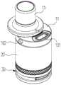
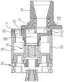
请参阅图1和图2,本实用新型提供了一种电子烟,该电子烟包括雾化器100 以及与雾化器100电性连接的电源装置,使用时,所述电源装置向雾化器100 提供电能,雾化器100在所述电源装置的电驱动作用下工作以加热烟液,使得烟液雾化生成烟雾,烟雾供用户吸食。Please refer to FIG. 1 and FIG. 2, the present invention provides an electronic cigarette, the electronic cigarette includes an
请参阅图3、图10和图11,雾化器100包括上盖组件10,上盖组件10包括具有注液口101的上盖11、注液盖12和限位件13,注液盖12可相对上盖11 滑动,滑动注液盖12可关闭或打开注液口101,上盖11上设置有滑槽102,滑槽102具有一开口1021,注液盖12至少部分通过开口1021可滑动地卡嵌于滑槽102内,限位件13安装在上盖11上;组装时先将注液盖12从开口1021安装进入滑槽102,再安装限位件13;组装后当滑动注液盖12至注液口101被打开时,注液盖12与限位件13相抵持从而限制注液盖12经由开口1021与滑槽 102相脱离。Please refer to FIG. 3 , FIG. 10 and FIG. 11 , the
组装上盖组件10时,先将注液盖12至少部分通过开口1021卡入滑槽102 内,然后将限位件13安装在上盖11上,限位件13用于阻挡注液盖12与滑槽102相脱离。使用时,注液盖12可相对上盖11于使用位置和注液位置之间移动,且,当注液盖12处于使用位置时,电子烟能够供用户抽吸烟雾操作;当注液盖12处于注液位置时,电子烟能够供用户注液操作,同时,注液盖12与限位件 13相抵持,使得限位件13对注液盖12继续移动起到阻挡作用,有效防止了注液盖12经由开口1021与滑槽102相脱离,方便了用户操作,提升了用户的使用体验。When assembling the
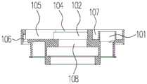
请参图3-图6,在一个具体的实施方式中,上盖11大致呈圆盘状结构,上盖11上面向注液盖12的端面沿上盖11的径向开设有凹槽103,注液口101开设在上盖11上面向注液盖12的端面且位于凹槽103的一侧,且注液口101和凹槽103依次设置在注液盖12相对上盖11由使用位置移动至注液位置的移动路径中。Referring to FIGS. 3 to 6 , in a specific embodiment, the
凹槽103上靠近注液口101的一端的两个相对侧壁上朝相对方向凸设有两个凸缘104,滑槽102由两个凸缘104与凹槽103的槽壁围设的空间构成,凹槽 103的内腔相对滑槽102远离注液口101的部分形成容置槽105,容置槽105与滑槽102相连通,开口1021由滑槽102远离注液口101的一端形成。Two
请参阅图7、图8,注液盖12大致呈圆盘状结构,注液盖12上面向上盖11 的端面的中心处凸设有滑块121,滑块121与容置槽105相配合且能够与滑槽 102滑动连接。组装上盖组件10时,将滑块121从上盖11的上方垂直放入容置槽105内,然后朝靠近注液口101的方向平推注液盖12,从而使得滑块121经由开口1021卡入至滑槽102内,通过滑块121与滑槽102之间的配合作用实现了注液盖12与上盖11二者间的滑动连接关系;然后将限位件13与上盖11连接。其中,凹槽103上设置有凸缘104的两个表面对滑块121的移动起到水平方向限位作用,凸缘104对滑块121的移动起到轴向限位作用。而当需要将注液盖12从上盖11上拆卸下来时,取下限位件13,朝远离注液口101的方向平推注液盖12,使得滑块121经由开口1021滑出至滑槽102的外部进而进入至容置槽105内,进入至容置槽105内的滑块121由上盖11的上方被垂直取出,如此,实现了注液盖12与上盖11二者间的拆卸功能。Please refer to FIG. 7 and FIG. 8 , the
请参阅图4、图5、图10和图11,在一个具体的实施方式中,上盖11上远离注液盖12的端面开设有安装槽106,安装槽106与凹槽103的容置槽105相连通,安装槽106用于安装限位件13。使用时,当滑块121卡入滑槽102内时,将限位件13从上盖11的底部安装在安装槽106内,此时,限位件13部分伸入至容置槽105内,从而使得容置槽105的部分空间被限位件13占据,如此,当用户远离注液口101平推注液盖12时,滑块121在未完全脱离滑槽102时,滑块121上远离注液口101的一端能够与限位件13相抵持,从而限制了滑块121 继续移动,进而防止了滑块121经由开口1021移出至滑槽102的外部。Please refer to FIG. 4 , FIG. 5 , FIG. 10 and FIG. 11 , in a specific embodiment, a mounting
可以理解地,在其他实施方式中,安装槽106还可以开设在上盖11的侧壁上,限位件13经由上盖11的侧部安装在安装槽106内,且部分限位件13伸入至容置槽105内,或者,安装槽106还可以省略,此时,限位件13直接安装在容置槽105内。如此,限位件13的安装位置并不做限定,只需满足限位件13 至少部分位于容置槽105内,且能够限制注液盖12经由开口1021与滑槽102 脱离即可。另外,本实施方式中,限位件13为限位销钉,可以理解地,限位件 13还可以是螺栓、螺钉等,此处不做限定。It can be understood that in other embodiments, the
可以理解地,在其他实施方式中,凹槽103还可以省略,滑槽102可以是由凸设在上盖11上面向注液盖12的端面且相对设置的两个限位块构成,限位件13安装在上盖11上面向注液盖12的端面且位于注液盖12的移动路径中,限位件13位于滑槽102远离注液口101的一侧,滑槽102的设置形式不做限定,只需保证注液盖12在滑槽102内于使用位置与注液位置之间移动且能够被限位件13限位即可。还可以理解地,在其他实施方式中,注液盖12整体位于滑槽 102内且可沿滑槽102移动,此时,注液口101开设在滑槽102的槽底壁上。It can be understood that in other embodiments, the
当注液盖12相对上盖11位于使用位置时,注液盖12盖设在注液口101上从而关闭注液口101,在一个具体的实施方式中,为了提升注液盖12与上盖11 之间的密封性,上盖11位于注液口101的周围设置有密封槽107,上盖组件10 还包括密封件14,密封件14收容于密封槽107内且密封包围在注液口101的外周,当注液盖12处于使用位置时,密封件14与注液盖12相抵持,从而防止了烟液泄漏。可以理解地,密封件14可以由硅胶或橡胶材料制成。When the
请参阅图5、图8、图10和图11,为了方便用户抽吸烟雾操作,上盖11上开设有出烟口108,注液盖12上开设有通气口122,当注液盖12相对上盖11 位于使用位置时,注液口101被注液盖12关闭,通气口122与出烟口108对位连通,此时,用户可进行抽吸操作,电子烟生成的烟雾在抽吸作用下可依次经由出烟口108及通气口122流出;当注液盖12相对上盖11位于注液位置时,通气口122与出烟口108错位,注液口101被打开,用户可进行注液操作。Please refer to FIG. 5, FIG. 8, FIG. 10 and FIG. 11. In order to facilitate the user's smoking operation, the
在一个具体的实施方式中,出烟口108开设在滑槽102的槽底壁上,且贯通上盖11上远离注液盖12的端面。通气口122开设在滑块121上且连通注液盖12的开口。可以理解地,在其他实施方式中,出烟口108还可以设置在滑槽 102的外部,只需满足注液盖12相对上盖11位于使用位置时,通气口122与出烟口108对位连通即可。In a specific embodiment, the
在一个具体的实施方式中,上盖组件10还包括烟嘴15,烟嘴15用于供用户含住以进行抽吸操作。烟嘴15呈两端贯通的管状结构,烟嘴15的一端与注液盖12连接且烟嘴15的内腔与注液盖12的开口连通,使用时,电子烟生成的烟雾在抽吸作用下依次经由出烟口108、通气口122及烟嘴15的内腔进入至用户口中。In a specific embodiment, the
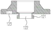
请参阅图9、图12和图13,为了防止注液盖12相对上盖11轻易被打开,导致误操作,本实用新型的上盖组件10还包括锁止结构16,锁止结构16包括可活动地设置在上盖11上的锁止件161,注液盖12上开设有相互连通的卡槽 123和导槽124,卡槽123与导槽124呈角度设置,导槽124的延伸方向与注液盖12相对上盖11的滑动方向一致,锁止件161与卡槽123及导槽124相配合且能够沿卡槽123及导槽124滑动,当锁止件161位于卡槽123内时,注液盖12关闭注液口101且无法相对上盖11滑动,当锁止件161活动至导槽124的一端时,注液盖12可相对上盖11滑动以打开注液口101。Please refer to FIGS. 9 , 12 and 13 , in order to prevent the
用户需要注液操作时,需要先将锁止件161由卡槽123活动至导槽124的一端,此时才可推动注液盖12,进而打开注液口101,有效防止了儿童在未活动锁止件161的情况下轻易打开注液盖12从而接触甚至误食烟液的情况发生,起到了儿童防护功能。When the user needs to inject liquid, the locking
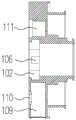
请参阅图6、图9,在一个具体的实施方式中,上盖11的侧壁上开设有容纳槽109,容纳槽109具有一贯通上盖11的侧壁的开口端,上盖11上面向注液盖12的端面开设有滑动槽110,滑动槽110与卡槽123相对应,且滑动槽110与容纳槽109相连通。锁止结构16还包括活动件162,活动件162可活动地安装在容纳槽109内,弹性件163收容于容纳槽109内。在一个实施方式中,锁止结构16还包括弹性件163,弹性件163沿活动件162的活动方向可伸缩地设置在活动件162与容纳槽109之间,具体地,弹性件163的一端与容纳槽109上远离容纳槽109的开口端的槽壁弹性抵持,弹性件163的另一端与活动件162 的一端弹性抵持。在一个实施方式中,活动件162的一端设置为台阶面,弹性件163套设在活动件162的外部,且弹性件163的一端与所述台阶面相抵持。可以理解地,活动件162的外壁上凹陷形成有凹陷槽,所述凹陷槽贯通活动件 162靠近弹性件163的端面,所述台阶面由所述凹陷槽远离所述弹性件163的槽壁构成,或者,活动件162的外壁上沿活动件162的径向凸设形成抵持缘,所述阶梯面由所述抵持缘上靠近弹性件163的端面构成,此处不做限定。按压活动件162可压缩弹性件163而活动件162回缩至容纳槽109内,解除对活动件 162的按压作用,活动件162在弹性件163的弹力作用下复位而向容纳槽109的外部伸出。需要说明的是,活动件162在未被按压时,活动件162远离弹性件 163的一端伸出至容纳槽109的外部,从而方便用户进行按压活动件162操作。锁止件161的一端穿过滑动槽110后与活动件162连接,当活动件162在被按压或复位的情况下于容纳槽109内活动时,锁止件161在活动件162的带动下沿滑动槽110滑动,并且,当注液盖12相对上盖11处于使用位置时,滑动槽 110与卡槽123对位,锁止件161远离活动件162的一端卡入卡槽123内,当注液盖12相对上盖11处于注液位置时,锁止件161远离活动件162的一端卡入导槽124内。锁止件161与活动件162之间的连接方式包括但不限于卡接、压接或螺纹连接。Referring to FIGS. 6 and 9 , in a specific embodiment, the side wall of the
在一个具体的实施方式中,卡槽123和导槽124之间的角度为90°。具体地,请参阅图4,滑动槽110沿上盖11的径向设置,且滑动槽110的延伸方向与滑槽102的延伸方向相互垂直。可以理解地,在其他未示出的实施方式中,卡槽123和导槽124之间还可以呈锐角或钝角,此处不做限定。In a specific embodiment, the angle between the
在一个具体的实施方式中,锁止件161为圆柱销,可以理解地,在其他实施方式中,锁止件161还可以是螺栓、螺钉等。另外,弹性件163为弹簧,可以理解地,在其他实施方式中,弹性件163还可以是诸如不锈钢弹片、铜制弹片等具有刚性和弹性的元件,此处不做限定。In a specific embodiment, the locking
可以理解地,在其他实施方式中,弹性件163还可以省略,此时,活动件 162安装在上盖11上,活动件162由弹性材料制成(例如,硅胶或橡胶),用户按压活动件162可使得活动件162发生变形从而带动锁止件161活动。还可以理解地,弹性件163及活动件162均可省略,此时,锁止件161的结构中部分与容纳槽109配合,部分与滑动槽110配合,锁止件161由弹性材料制成(例如,硅胶或橡胶),用于直接按压锁止件161上与容纳槽109配合的部分便可使得锁止件161上与滑动槽110配合的部分沿滑动槽110活动。还可以理解地,滑动槽110还可以省略,此时,容纳槽109贯通上盖11上面向注液盖12的端面,锁止件161远离活动件162的一端可无需穿过滑动槽110直接卡入卡槽123 或导槽124内。It can be understood that in other embodiments, the
另外,在其他未示出的实施方式中,在省略弹性件163的基础上,活动件162还可以由硬质材料制成,只需使得活动件162与容纳槽109的槽壁之间具有一定的活动阻力即可,以避免活动件162轻易活动,用户使用时,需要通过推动或拉动活动件162操作才可使活动件162活动,进一步使得锁止件161在活动件162的带动下移动。In addition, in other unshown embodiments, on the basis of omitting the
请参阅图4、图12和图13,在一个具体的实施方式中,上盖11上面向注液盖12的端面开设有安装凹槽111,上盖组件10还包括抵持件17,抵持件17 安装在安装凹槽111内,当注液盖12与上盖11连接时,抵持件17与注液盖12 上面向上盖11的端面相抵持,如此,由于抵持件17与注液盖12之间的抵持关系,使得推动注液盖12时需要克服一定的阻力,保证了注液盖12能够平稳滑动,同时也增强了用户的操作手感。可以理解地,抵持件17由硅胶或橡胶材料制成。Please refer to FIG. 4 , FIG. 12 and FIG. 13 , in a specific embodiment, a mounting
本实施方式中,上盖组件10的使用过程如下:用户需要注液时,按压活动件162,活动件162压缩弹性件163于容纳槽109内活动,进而带动锁止件161 沿卡槽123滑动,当锁止件161活动至导槽124的一端时,相对上盖11平推注液盖12,当注液盖12与限位件13相抵持时,注液盖12无法进行移动,此时,注液口101被注液盖12打开,用户可通过注液口101注液操作。注液完毕后,相对上盖11反向平推注液盖12,锁止件161沿导槽124滑动,当锁止件161活动至卡槽123的一端时,活动件162在弹性件163的弹力作用下复位,进而带动锁止件161沿卡槽123滑动并使得锁止件161卡入卡槽123内,此时,注液盖12关闭注液口101且无法相对上盖11滑动。In this embodiment, the use process of the
请再次参阅图10,本实用新型的雾化器100还包括储液件20、底座组件30 以及雾化头40,其中,上盖组件10安装在储液件20的一端,底座组件30相对上盖组件10安装在储液件20的另一端,雾化头40安装在储液件20的内部。储液件20内设置有储液腔201,储液腔201用于存储烟液,具体地,雾化头40 收容于储液腔201内,上盖11与储液件20上相对底座组件30的一端连接,注液口101与储液腔201连通,用户注液操作时,即通过注液口101向储液腔201 内注入烟液。用户使用电子烟时,电源装置向雾化头40提供电能,雾化头40 加热储液腔201内的烟液,使得烟液雾化生成烟雾,烟雾通过上盖组件10后进入至用户口中,以供用户吸食。Please refer to FIG. 10 again, the
在一个具体的实施方式中,储液件20大致呈两端贯通的中空筒状结构,储液腔201由储液件20的内腔形成。储液件20由透明或半透明材料制成,使得用户能够透过储液件20观察储液腔201内烟液的剩余量,方便用户及时注入烟液,本实施方式中,储液件20由玻璃制成。可以理解地,在其他实施方式中,储液件20外还可以再套设由硬质材料(如不锈钢)制成的防护套,以用于保护储液件20。在其它实施方式中,储液件20可以选用不透明材料。In a specific embodiment, the
在一个具体的实施方式中,底座组件30包括相对上盖组件10安装在储液件20一端的底座31、装设于底座31上的第一电极32和电极套33,以及可转动地套设于底座31外部的调气环34。In a specific embodiment, the
底座31大致呈上端具有开口的中空筒状结构,底座31的底部中心处向下延伸形成与底座31的内腔连通的连接管311,第一电极32安装在连接管311内,电极套33套设于第一电极32的上端,且与雾化头40电性连接。具体地,所述电源装置与底座31的连接管311螺纹连接,使得第一电极32与所述电源装置电性连接。本实施方式中,第一电极32与连接管311之间夹设有第一绝缘件35,电极套33与连接管311之间夹设有第二绝缘件36,从而实现电性隔离的目的。第一绝缘件35和第二绝缘件36由绝缘材料制成,可以理解地,第一绝缘件35和第二绝缘件36包括但不限于硅胶或橡胶。The
调气环34大致呈两端贯通的筒状结构,底座31的周壁上设置有与底座31 的内腔连通的进气孔312,调气环34的周壁上对应进气孔312设置有与外界连通的调气孔341。当转动调气环34时,可以调节调气孔341与进气孔312的连通面积,方便使用者根据需要调节进气量的大小。The air-adjusting
在一个具体的实施方式中,雾化头40包括收容于储液腔201内的雾化套管 41、收容于雾化套管41内的发热组件42以及安装在雾化套管41的底部的第二电极43。其中,雾化套管41的上下两端贯通,雾化套管41的下端与底座31连接,雾化套管41的上端与上盖11连接,雾化套管41的内腔形成有与出烟口108 连通的雾化腔401,雾化套管41的侧壁上设置有连通储液腔201与雾化腔401 的进液孔402。发热组件42设于雾化腔401内,发热组件42包括相互接触的发热件421和导液件422,导液件422用于经由进液孔402吸取储液腔201内的烟液,发热件421用于加热导液件422上的烟液,使烟液生成烟雾。其中,发热件421可为发热丝、发热网或者发热片等,导液件422可为棉花、纤维绳、多孔陶瓷或多孔石墨等。另外,第二电极43的下端与电极套33接触并电性连接,第二电极43的上端与发热件421电性连接;如此,第一电极32、连接管311分别与电源装置的正、负极电性连接,而发热件421的两端分别与第二电极43和雾化套管41电性连接,从而实现所述电源装置向发热件421提供电能。可以理解的,在其他实施方式中,雾化头40还可以采用超声雾化头、电磁感应加热雾化头等,此处并不做限定。In a specific embodiment, the atomizing
在一个实施方式中,第二电极42为中空的筒状结构,且第二电极42的两端分别与底座31的内腔及雾化腔401相连通,用户抽吸操作时,外部气体能够依次经由调气孔341、进气孔312、底座31的内腔及第二电极42的内腔进入至雾化腔401内并与烟雾混合,混合后的气体依次经由出烟口108、通气口122及烟嘴15后进入至用户口中。In one embodiment, the
本实用新型提供的上盖组件10,用户平推注液盖12至注液位置时,电子烟能够供用户注液操作,同时,注液盖12与限位件13相抵持,使得限位件13对注液盖12继续移动起到阻挡作用,有效防止了注液盖12经由开口1021与滑槽 102相脱离,方便了用户操作,提升了用户的使用体验。In the
本实用新型提供的雾化器100及电子烟,因其具有上述上盖组件10全部的技术特征,故具有与上述上盖组件10相同的技术效果。Since the
以上述依据本实用新型的理想实施例为启示,通过上述的说明内容,相关的工作人员完全可以在不偏离本实用新型的范围内,进行多样的变更以及修改。本项实用新型的技术范围并不局限于说明书上的内容,必须要根据权利要求范围来确定其技术性范围。Taking the above ideal embodiments according to the present invention as inspiration, through the above descriptions, relevant staff can make various changes and modifications without departing from the scope of the present invention. The technical scope of the present utility model is not limited to the content in the description, and its technical scope must be determined according to the scope of the claims.
Claims (10)
Priority Applications (1)
| Application Number | Priority Date | Filing Date | Title |
|---|---|---|---|
| CN201921060489.6UCN211794314U (en) | 2019-07-08 | 2019-07-08 | Atomizer and electronic cigarette |
Applications Claiming Priority (1)
| Application Number | Priority Date | Filing Date | Title |
|---|---|---|---|
| CN201921060489.6UCN211794314U (en) | 2019-07-08 | 2019-07-08 | Atomizer and electronic cigarette |
Publications (1)
| Publication Number | Publication Date |
|---|---|
| CN211794314Utrue CN211794314U (en) | 2020-10-30 |
Family
ID=72995780
Family Applications (1)
| Application Number | Title | Priority Date | Filing Date |
|---|---|---|---|
| CN201921060489.6UActiveCN211794314U (en) | 2019-07-08 | 2019-07-08 | Atomizer and electronic cigarette |
Country Status (1)
| Country | Link |
|---|---|
| CN (1) | CN211794314U (en) |
Cited By (1)
| Publication number | Priority date | Publication date | Assignee | Title |
|---|---|---|---|---|
| EP4026442A1 (en)* | 2021-01-11 | 2022-07-13 | JT International S.A. | Aerosol generation assembly and method for using such assembly |
- 2019
- 2019-07-08CNCN201921060489.6Upatent/CN211794314U/enactiveActive
Cited By (1)
| Publication number | Priority date | Publication date | Assignee | Title |
|---|---|---|---|---|
| EP4026442A1 (en)* | 2021-01-11 | 2022-07-13 | JT International S.A. | Aerosol generation assembly and method for using such assembly |
Similar Documents
| Publication | Publication Date | Title |
|---|---|---|
| EP3545776A1 (en) | E-liquid storage assembly, atomizer, and electronic cigarette having same | |
| CN211746942U (en) | Cover assembly, atomizer and aerosol generating device | |
| CN108208936A (en) | Atomizer and its electronic cigarette | |
| WO2019037701A1 (en) | Upper cover assembly, atomizer, and electronic cigarette | |
| CN210960415U (en) | Liquid injection structure, atomizer and its aerosol generating device | |
| CN209346110U (en) | Battery case and electronic cigarette | |
| CN105919163A (en) | Atomizer and electronic cigarette thereof | |
| CN210275888U (en) | Atomizers and Electronic Cigarettes | |
| CN211794314U (en) | Atomizer and electronic cigarette | |
| CN209883062U (en) | Atomizers and Electronic Cigarettes | |
| CN210275906U (en) | Liquid injection structure and atomizer, electronic cigarette | |
| CN209518264U (en) | Atomizer and electronic cigarette | |
| CN210158011U (en) | Atomizers and Electronic Cigarettes | |
| CN210137810U (en) | Cartridges and Electronic Cigarettes | |
| CN217184864U (en) | Nebulizer and aerosol generating device | |
| CN216293022U (en) | Electronic cigarette atomization assembly and electronic cigarette | |
| CN110742313A (en) | Atomizers and Electronic Atomizers | |
| CN211794343U (en) | Atomizer and electronic cigarette | |
| CN212065675U (en) | Nebulizer and aerosol generating device | |
| CN206413753U (en) | Liquid storage component, atomizer and electronic cigarette | |
| CN209420960U (en) | Power supply device and electronic cigarette | |
| CN217826791U (en) | Electronic atomizer | |
| CN208030266U (en) | Atomizer and electronic cigarette | |
| CN207821093U (en) | Atomizer and electronic cigarette | |
| CN211832818U (en) | Atomizer and electronic atomization device |
Legal Events
| Date | Code | Title | Description |
|---|---|---|---|
| GR01 | Patent grant | ||
| GR01 | Patent grant |