CN211693390U - Electrically-driven rotary power unit and quadruped robot applying same - Google Patents
Electrically-driven rotary power unit and quadruped robot applying sameDownload PDFInfo
- Publication number
- CN211693390U CN211693390UCN202020281851.9UCN202020281851UCN211693390UCN 211693390 UCN211693390 UCN 211693390UCN 202020281851 UCN202020281851 UCN 202020281851UCN 211693390 UCN211693390 UCN 211693390U
- Authority
- CN
- China
- Prior art keywords
- gear
- output
- power unit
- planetary
- bearing
- Prior art date
- Legal status (The legal status is an assumption and is not a legal conclusion. Google has not performed a legal analysis and makes no representation as to the accuracy of the status listed.)
- Active
Links
Images


Landscapes
- Retarders (AREA)
Abstract
Translated fromChinese
Description
Translated fromChinese技术领域technical field
本实用新型涉及一种电驱动回转动力单元以及应用其的四足机器人,属于动力单元以及机器人设备技术领域。The utility model relates to an electric drive rotary power unit and a quadruped robot applying the same, belonging to the technical field of power units and robot equipment.
背景技术Background technique
中国专利(公开号 CN208845648U)公开了一种机器人关节处的电驱动回转动力单元以及应用其的一种四足机器人,其包括电机基座、电机单元和减速器单元,电机单元和减速器单元分别设于电机基座内;电机单元包括电机转子;减速器单元包括太阳轮、行星轮、齿圈和行星架;行星轮分别与太阳轮和齿圈啮合,行星架用于输出回转动力单元的动力;电机转子与太阳轮同轴设置且固定连接。将太阳轮与转子总成上的电机转子固定连接,结构紧凑、体积小,缩小了整个动力单元的轴向长度的同时也减轻了回转动力单元的重量;避免了现有技术中将电机单元和减速器单元作为两个独立单元而采用联轴器等机械方式连接带来的结构不紧凑、整个动力单元体积大等问题。Chinese Patent (Publication No. CN208845648U) discloses an electrically driven rotary power unit at a robot joint and a quadruped robot using the same, which includes a motor base, a motor unit and a reducer unit. The motor unit and the reducer unit are respectively Set in the motor base; the motor unit includes the motor rotor; the reducer unit includes the sun gear, the planetary gear, the ring gear and the planet carrier; the planetary gear is meshed with the sun gear and the ring gear respectively, and the planetary carrier is used to output the power of the rotary power unit ; The motor rotor and the sun gear are coaxially arranged and fixedly connected. The sun gear is fixedly connected with the motor rotor on the rotor assembly, the structure is compact and the volume is small, the axial length of the entire power unit is reduced, and the weight of the rotary power unit is also reduced; As two independent units, the reducer unit is connected by mechanical means such as coupling, which brings about the problems of uncompact structure and large volume of the whole power unit.
但上述动力单元的动力输出需依靠减速器行星架减速,为了保持机器人关节的紧凑,机器人关节内的空腔尺寸受限制,因此机器人动力单元在关节空腔限制下,只能采用一级行星减速器进行减速,导致其减速比无法做的太高。更一步,该结构的动力单元厚度尺寸极难进一步减小;难以应用到更小的场合。However, the power output of the above-mentioned power unit needs to be decelerated by the reducer planetary carrier. In order to keep the robot joint compact, the cavity size in the robot joint is limited. Therefore, the robot power unit can only use one-level planetary deceleration under the limitation of the joint cavity. The speed reducer is decelerated, so that its deceleration ratio cannot be too high. Furthermore, it is extremely difficult to further reduce the thickness and size of the power unit of this structure; it is difficult to apply to smaller occasions.
实用新型内容Utility model content
针对现有技术的缺陷,本实用新型的目的在于提供一种具有双齿轮结构的行星轮和双齿圈,能够有效提高单级减速器的减速比调节范围;同时设置输出齿圈进行力矩输出,使其具有更大的减速比;进而能够有效减少动力单元尺寸及重量,使其适用范围广的电驱动回转动力单元以及应用其的四足机器人。In view of the defects of the prior art, the purpose of this utility model is to provide a planetary gear and a double ring gear with a double gear structure, which can effectively improve the adjustment range of the reduction ratio of the single-stage reducer; It has a larger reduction ratio; further, it can effectively reduce the size and weight of the power unit, making it suitable for a wide range of electric drive rotary power units and quadruped robots that apply it.
为实现上述目的,本实用新型的技术方案为:For achieving the above object, the technical scheme of the present utility model is:
一种电驱动回转动力单元,包括电机、减速器单元,An electric drive rotary power unit, comprising a motor and a reducer unit,
所述减速器单元包括与电机转子转轴固接的太阳轮、配合太阳轮传动的行星轮、用于与行星轮啮合的固定齿圈、用于配合行星轮力矩输出的输出齿圈;The speed reducer unit includes a sun gear fixedly connected with the rotor shaft of the motor, a planetary gear matched with the transmission of the sun gear, a fixed ring gear used for meshing with the planetary gear, and an output ring gear used to match the torque output of the planetary gear;
所述行星轮包括与太阳轮齿接的行星输入齿轮、与输出齿圈齿接的行星输出齿轮;The planetary gear includes a planetary input gear toothed with the sun gear and a planetary output gear toothed with the output ring gear;
所述行星输入齿轮与行星输出齿轮叠置固连在一起,两者同步转动;The planetary input gear and the planetary output gear are superimposed and fixed together, and the two rotate synchronously;
所述电机驱动太阳轮旋转,进而太阳轮带动行星轮的行星输入齿轮转动,与行星输入齿轮同步转动的行星输出齿轮带动输出齿圈转动输出,完成电机的减速输出。The motor drives the sun gear to rotate, and then the sun gear drives the planetary input gear of the planetary gear to rotate, and the planetary output gear that rotates synchronously with the planetary input gear drives the output ring gear to rotate and output, completing the deceleration output of the motor.
本实用新型经过不断探索以及试验,打破现有的一级减速器设计偏见,采用具有双齿轮结构的行星轮和双齿圈,有效节约了轴向空间,增大了减速比的设计范围,扩大了动力单元的使用范围,进一步,有效减小了动力单元的设计和加工难度。同时设置输出齿圈进行力矩输出,使其具有更大的减速比,进一步减少动力单元尺寸,使其适用范围广。After continuous exploration and testing, the utility model breaks the design prejudice of the existing primary reducer, adopts the planetary gear and the double ring gear with the double gear structure, effectively saves the axial space, increases the design range of the reduction ratio, and expands the The use range of the power unit is increased, and further, the design and processing difficulty of the power unit is effectively reduced. At the same time, the output ring gear is set for torque output, so that it has a larger reduction ratio, which further reduces the size of the power unit and makes it suitable for a wide range of applications.
进而,本实用新型的减速器能够布置在电机中心空腔位置或靠近电机中心空腔前位置,进一步节约轴向空间。Furthermore, the speed reducer of the present invention can be arranged at the position of the central cavity of the motor or at a position close to the front of the central cavity of the motor, thereby further saving axial space.
作为优选技术措施:As the preferred technical measures:
所述太阳轮的齿数少于行星输入齿轮的齿数,两者外啮合;The number of teeth of the sun gear is less than the number of teeth of the planetary input gear, and the two are externally meshed;
所述行星输入齿轮的齿数多于行星输出齿轮的齿数,两者固连同轴布置;The number of teeth of the planetary input gear is more than the number of teeth of the planetary output gear, and the two are fixed together with the shaft;
所述行星输出齿轮与输出齿圈内啮合,使其结构紧凑,进一步提高减速比调节范围。The planetary output gear meshes with the output ring gear, so that the structure is compact and the adjustment range of the reduction ratio is further improved.
所述太阳轮、行星输入齿轮、行星输出齿轮模数相同,便于结构设计。The modules of the sun gear, the planetary input gear and the planetary output gear are the same, which is convenient for structural design.
作为优选技术措施:As the preferred technical measures:
所述固定齿圈圈内均布齿接三组所述行星轮;Three groups of said planetary gears are connected with evenly distributed teeth in said fixed ring gear;
三组行星轮的行星输入齿轮分别与所述太阳轮外啮合。The planetary input gears of the three sets of planetary gears are respectively meshed with the sun gear.
三组行星轮均匀分布,间隔120度,能够有效增加动力单元的力矩输出能力以及结构强度。The three sets of planetary gears are evenly distributed with an interval of 120 degrees, which can effectively increase the torque output capacity and structural strength of the power unit.
作为优选技术措施:As the preferred technical measures:
三组行星轮的行星输出齿轮齿接同一浮动太阳轮;The planetary output gear teeth of the three sets of planetary gears are connected to the same floating sun gear;
所述行星输出齿轮和浮动太阳轮位于输出齿圈圈内。The planetary output gear and the floating sun gear are located in the output ring gear ring.
浮动太阳轮不参与减速器减速作用,主要用来改善减速器受力稳定性和可靠性。The floating sun gear does not participate in the deceleration effect of the reducer, and is mainly used to improve the force stability and reliability of the reducer.
作为优选技术措施:As the preferred technical measures:
所述输出齿圈的外侧端固接一用于连接机器人关节外部部件的输出端盖,The outer end of the output ring gear is fixedly connected with an output end cover for connecting the external parts of the robot joint,
所述输出端盖与输出齿圈之间设有轴承三;A bearing three is arranged between the output end cover and the output gear ring;
所述轴承三的内圈与所述输出端盖和输出齿圈固定连接,The inner ring of the third bearing is fixedly connected with the output end cover and the output gear ring,
所述轴承三的外圈与电机壳体固连;所述轴承三为交叉字轴承或深沟球轴承;结构简单实用,便于生产制造。The outer ring of the third bearing is fixedly connected with the motor housing; the third bearing is a cross bearing or a deep groove ball bearing; the structure is simple and practical, and is convenient for production and manufacture.
作为优选技术措施:As the preferred technical measures:
所述电机包括定子和外转子;the motor includes a stator and an outer rotor;
所述定子固定在一上端盖,所述外转子侧支撑端面相对定子远离输出端盖;The stator is fixed on an upper end cover, and the outer rotor side supporting end face is far away from the output end cover relative to the stator;
或所述定子固定在一下端盖上,所述外转子侧支撑端面相对定子靠近输出端盖;Or the stator is fixed on the lower end cover, and the support end face of the outer rotor side is close to the output end cover relative to the stator;
所述外转子与定子通过连接件以及轴承转动连接。The outer rotor and the stator are rotatably connected through a connecting piece and a bearing.
当定子固定在下端盖上,便于上端盖预留空腔,用于固定驱动板和电路盖板,结构简单、实用。When the stator is fixed on the lower end cover, it is convenient for the upper end cover to reserve a cavity for fixing the driving board and the circuit cover, and the structure is simple and practical.
本领域技术人员,可根据实际情况,灵活选择定子固定位置,容易想到的是,上端盖、下端盖以及相应部件的形状可根据定子的固定位置做出相应改变,这里不再赘述。Those skilled in the art can flexibly select the fixed position of the stator according to the actual situation. It is easy to think that the shapes of the upper end cover, the lower end cover and the corresponding parts can be changed according to the fixed position of the stator, which will not be repeated here.
作为优选技术措施:As the preferred technical measures:
所述外转子一端通过轴承一与电机壳体转动连接,另一端通过轴承二与输出端盖转动连接;One end of the outer rotor is rotatably connected with the motor housing through the first bearing, and the other end is rotatably connected with the output end cover through the second bearing;
所述轴承一与电机壳体配合的位置,在上端盖或下端盖上;The position where the bearing is matched with the motor housing is on the upper end cover or the lower end cover;
所述轴承二的内圈配合在外转子转轴上,其外圈配合在输出端盖上;所述固定齿圈与电机壳体固定连接,所述固定齿圈布置在定子内圈空腔内或靠近定子内圈空腔的位置。The inner ring of the second bearing is fitted on the shaft of the outer rotor, and the outer ring is fitted on the output end cover; the fixed ring gear is fixedly connected with the motor housing, and the fixed ring gear is arranged in the inner ring cavity of the stator or Close to the inner ring cavity of the stator.
本实用新型结构简单实用,方案切实可行,便于生产制造。The structure of the utility model is simple and practical, the scheme is practical and feasible, and the production and manufacture are convenient.
作为优选技术措施:As the preferred technical measures:
所述外转子上的轴上设置用于限制浮动太阳轮及轴承二轴向窜动的卡簧。The shaft on the outer rotor is provided with a retaining spring for restricting the axial movement of the floating sun gear and the bearing.
浮动太阳轮轴向窜动由外转子转轴上的轴肩和轴承二来限制,但留下一定的窜动空间,可以在外转子上的轴上增加卡簧来限制其轴向窜动。The axial movement of the floating sun gear is limited by the shoulder and bearing two on the outer rotor shaft, but a certain movement space is left, and a circlip can be added to the shaft on the outer rotor to limit its axial movement.
作为优选技术措施:As the preferred technical measures:
所述下端盖设有用于安放电路元件的环状空间,便于装配线缆以及电路板,所述电路板上有编码器芯片,所述编码器芯片与电机转子端部的编码器配合。The lower end cover is provided with an annular space for placing circuit elements, which is convenient for assembling cables and a circuit board. The circuit board has an encoder chip, and the encoder chip cooperates with the encoder at the end of the motor rotor.
一种四足机器人,包括上述的一种电驱动回转动力单元。A quadruped robot includes the above-mentioned electric drive rotary power unit.
本实用新型的四足机器人采用具有双齿轮结构的行星轮和双齿圈,能够有效提高单级减速器的减速比调节范围;同时设置输出齿圈进行力矩输出,使其具有更大的减速比调节范围;进而能够有效减少动力单元尺寸及重量,使其能够装配在机器人关节内靠近电机定子中心的空腔内,进一步使得四足机器人结构紧凑,占用空间小。The quadruped robot of the utility model adopts a planetary gear with a double gear structure and a double ring gear, which can effectively improve the adjustment range of the reduction ratio of the single-stage reducer; at the same time, the output ring gear is set for torque output, so that it has a larger reduction ratio. Adjustment range; further, the size and weight of the power unit can be effectively reduced, so that it can be assembled in the cavity of the robot joint close to the center of the motor stator, further making the quadruped robot compact in structure and small in space.
与现有技术相比,本实用新型具有以下有益效果:Compared with the prior art, the utility model has the following beneficial effects:
本实用新型经过不断探索以及试验,打破现有的一级减速器设计偏见,采用具有双齿轮结构的行星轮和双齿圈,有效节约了轴向空间,增大了减速比的设计范围,增大了动力单元的使用范围,进一步,有效减小了动力单元的设计和加工难度。同时设置输出齿圈进行力矩输出,使其具有更大的减速比调节范围,进一步减少动力单元尺寸,使其适用范围广。After continuous exploration and testing, the utility model breaks the design prejudice of the existing primary reducer, adopts the planetary gear and the double ring gear with the double gear structure, effectively saves the axial space, increases the design range of the reduction ratio, and increases the The use range of the power unit is enlarged, and further, the design and processing difficulty of the power unit is effectively reduced. At the same time, the output ring gear is set for torque output, so that it has a larger reduction ratio adjustment range, further reduces the size of the power unit, and makes it a wide range of applications.
附图说明Description of drawings
图1是本实用新型的整体爆炸图;Fig. 1 is the overall exploded view of the present utility model;
图2是本实用新型的减速器单元的爆炸图;Fig. 2 is the exploded view of the reducer unit of the present utility model;
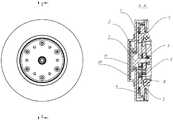
图3是本实用新型一种电机装配结构示图以及沿A-A方向全剖视图;3 is a schematic diagram of a motor assembly structure of the present utility model and a full cross-sectional view along the A-A direction;
图4是本实用新型另一种电机装配结构示图以及沿B-B方向全剖视图;4 is a schematic diagram of another motor assembly structure of the present invention and a full cross-sectional view along the B-B direction;
图5是本实用新型轴承一一种安装位置结构示图以及沿C-C方向全剖视图。Fig. 5 is a structural diagram of a bearing of the present utility model one installation position and a full cross-sectional view along the C-C direction.
附图标记说明:Description of reference numbers:
1、下端盖;2、轴承一;3、外转子;4、定子;5、减速器单元;51、固定齿圈;52、太阳轮;53、行星轮组;54、衬套;55、浮动太阳轮;56、输出齿圈;531、行星输入齿轮;532、行星输出齿轮;6、轴承二;7、上端盖;8、轴承三;9、输出端盖;10.驱动板;11、电路盖板。1. Lower end cover; 2. Bearing one; 3. Outer rotor; 4. Stator; 5. Reducer unit; 51. Fixed ring gear; 52. Sun gear; 53. Planetary gear set; 54. Bushing; 55. Floating Sun gear; 56, output ring gear; 531, planetary input gear; 532, planetary output gear; 6, bearing two; 7, upper end cover; 8, bearing three; 9, output end cover; 10. drive board; 11, circuit cover.
具体实施方式Detailed ways
为了使本实用新型的目的、技术方案及优点更加清楚明白,以下结合附图及实施例,对本实用新型进行进一步详细说明。应当理解,此处所描述的具体实施例仅仅用以解释本实用新型,并不用于限定本实用新型。In order to make the purpose, technical solutions and advantages of the present utility model more clearly understood, the present utility model will be further described in detail below with reference to the accompanying drawings and embodiments. It should be understood that the specific embodiments described herein are only used to explain the present invention, and are not intended to limit the present invention.
相反,本实用新型涵盖任何由权利要求定义的在本实用新型的精髓和范围上做的替代、修改、等效方法以及方案。进一步,为了使公众对本实用新型有更好的了解,在下文对本实用新型的细节描述中,详尽描述了一些特定的细节部分。对本领域技术人员来说没有这些细节部分的描述也可以完全理解本实用新型。On the contrary, the present invention covers any alternatives, modifications, equivalents and arrangements made within the spirit and scope of the present invention as defined by the claims. Further, in order to make the public have a better understanding of the present invention, some specific details are described in detail in the following detailed description of the present invention. Those skilled in the art can fully understand the present invention without the description of these detailed parts.
需要说明的是,当两个元件被称为“固定连接”或“固接”时,两个元件可以直接连接或者也可以存在居中的元件。相反,当元件被称作“直接在”另一元件“上”时,不存在中间元件。本文所使用的术语“上”、“下”以及类似的表述只是为了说明的目的。It should be noted that when two elements are referred to as "fixedly connected" or "fixed", the two elements may be directly connected or an intervening element may also exist. In contrast, when an element is referred to as being "directly on" another element, there are no intervening elements present. The terms "upper," "lower," and similar expressions used herein are for illustrative purposes only.
如图1-3所示,一种电驱动回转动力单元,包括电机、减速器单元5,所述减速器单元5包括与电机转子转轴固接的太阳轮52、配合太阳轮52传动的行星轮、用于与行星轮啮合的固定齿圈51、配合行星轮传动的输出齿圈56;As shown in Figures 1-3, an electric drive rotary power unit includes a motor and a
所述行星轮包括与太阳轮52齿接的行星输入齿轮531、与输出齿圈56齿接的行星输出齿轮532;The planetary gear includes a
所述行星输入齿轮531与行星输出齿轮532叠置固连在一起,两者同步转动;The
所述电机驱动太阳轮52旋转,进而太阳轮52带动行星轮的行星输入齿轮531转动,与行星输入齿轮531同步转动的行星输出齿轮532带动输出齿圈56转动输出。The motor drives the
本实用新型经过不断探索以及试验,打破现有的一级减速器设计偏见,采用具有双齿轮结构的行星轮和双齿圈,有效节约了轴向空间,增大了减速比的设计范围,增大了动力单元的使用范围,进一步,有效减小了动力单元的设计和加工难度。同时设置输出齿圈56进行力矩输出,使其具有更大的减速比调节范围,进一步减少动力单元尺寸,使其适用范围广。After continuous exploration and testing, the utility model breaks the design prejudice of the existing primary reducer, adopts the planetary gear and the double ring gear with the double gear structure, effectively saves the axial space, increases the design range of the reduction ratio, and increases the The use range of the power unit is enlarged, and further, the design and processing difficulty of the power unit is effectively reduced. At the same time, the
本实用新型行星轮结构的一种具体实施例:A specific embodiment of the planetary gear structure of the present utility model:
所述行星输入齿轮531的齿数多于行星输出齿轮532的齿数,两者固连同轴布置;The number of teeth of the
所述行星输入齿轮531与太阳轮52外啮合,所述行星输出齿轮532与输出齿圈56内啮合,使其结构紧凑,进一步提高减速比调节范围。The
所述太阳轮、行星输入齿轮、行星输出齿轮模数相同,便于结构设计。The modules of the sun gear, the planetary input gear and the planetary output gear are the same, which is convenient for structural design.
本实用新型行星轮数量一种具体实施例:A specific embodiment of the number of planetary gears of the present utility model:
所述固定齿圈51圈内均布齿接三组所述行星轮;The 51 circles of the fixed ring gear are evenly distributed with teeth connected to three sets of the planetary gears;
三组行星轮的行星输入齿轮531分别与所述太阳轮52外啮合。The planetary input gears 531 of the three sets of planetary gears are respectively externally meshed with the
三组行星轮均匀分布,间隔120度,能够有效增加动力单元的力矩输出能力以及结构强度。The three sets of planetary gears are evenly distributed with an interval of 120 degrees, which can effectively increase the torque output capacity and structural strength of the power unit.
本实用新型增设浮动太阳轮55的一种具体实施例:A specific embodiment of the utility model adding a floating sun gear 55:
三组行星轮的行星输出齿轮532齿接同一浮动太阳轮55;The teeth of the planetary output gears 532 of the three sets of planetary gears are connected to the same floating
所述行星输出齿轮532和浮动太阳轮55位于输出齿圈56圈内。The
浮动太阳轮55不参与减速器减速作用,主要用来改善减速器受力稳定性和可靠性。The floating
本实用新型增设输出端盖9一种具体实施例:The utility model adds a specific embodiment of the output end cover 9:
所述输出齿圈56的外侧端固接一用于连接机器人关节外部部件的输出端盖9,The outer end of the
所述输出端盖9与输出齿圈56之间设有轴承三8;A bearing 38 is provided between the
所述轴承三8的内圈分布与所述输出端盖9和输出齿圈56固定连接,The inner ring distribution of the
所述轴承三8的外圈与电机壳体固连;所述轴承三为交叉字轴承或深沟球轴承;结构简单实用,便于生产制造。The outer ring of the
本实用新型电机装配结构的一种具体实施例:A specific embodiment of the motor assembly structure of the present utility model:
所述电机包括定子4和外转子3;The motor includes a
所述定子4固定在上端盖7上,并与外转子3转动连接。The
所述外转子3一端通过轴承一2与一下端盖1转动连接,另一端通过轴承二6与输出端盖9转动连接;所述下端盖1设有用于安放电路元件的环状空间,便于装配线缆以及电路板,所述电路板上有编码器芯片,所述编码器芯片与电机转子端部的编码器配合。One end of the
所述轴承一与电机壳体配合的位置,可以在上端盖或下端盖上。The position where the bearing is matched with the motor housing may be on the upper end cover or the lower end cover.
所述轴承二6的内圈配合在外转子3上,其外圈配合在输出端盖9上;结构简单实用,方案切实可行,便于生产制造。The inner ring of the
所述固定齿圈51与电机壳体固定连接,所述固定齿圈51布置在电机定子4内圈空腔内或靠近定子4内圈空腔的位置。The fixed
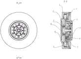
如图4所示,本实用新型电机装配结构的另一种具体实施例:As shown in Figure 4, another specific embodiment of the motor assembly structure of the present utility model:
所述电机包括定子4和外转子3;The motor includes a
所述定子4固定在一下端盖1上,所述外转子3侧支撑端面相对定子4靠近输出端盖9;所述外转子3与定子4通过连接件以及轴承转动连接。The
定子4固定在下端盖上,便于上端盖预留空腔,用于固定驱动板10和电路盖板11,结构简单、实用。The
本领域技术人员,可根据实际情况,灵活选择定子固定位置,容易想到的是,上端盖、下端盖以及相应部件的形状可根据定子的固定位置做出相应改变,这里不再赘述。Those skilled in the art can flexibly select the fixed position of the stator according to the actual situation. It is easy to think that the shapes of the upper end cover, the lower end cover and the corresponding parts can be changed according to the fixed position of the stator, which will not be repeated here.
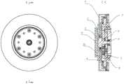
如图5所示,本实用新型轴承一2安装位置另一种实施例。As shown in FIG. 5 , another embodiment of the installation position of the bearing-2 of the present invention is shown.
本实用新型增设卡簧的一种具体实施例:A specific embodiment of the utility model adding a circlip:
所述外转子3上的轴上设置用于限制浮动太阳轮55及轴承二轴向窜动的卡簧。The shaft on the
浮动太阳轮55轴向窜动由外转子3上的轴肩和轴承二6来限制,但留下一定的窜动空间,可以在外转子3上的轴上增加卡簧来限制其轴向窜动。The axial movement of the floating
本实用新型应用电驱动回转动力单元的四足机器人实施例:The utility model applies the quadruped robot embodiment of the electric drive rotary power unit:
一种四足机器人,包括上端盖7、下端盖1、电机、减速器单元5、输出端盖9。A quadruped robot includes an
所述电机包括定子4和外转子3;所述减速器单元5包括固定齿圈51、太阳轮52、行星轮、衬套54、浮动太阳轮55、输出齿圈56。The motor includes a
本实用新型一种优选装配实施例:A preferred assembly embodiment of the present utility model:
所述定子4固定连接在上端盖7上,两者胶水粘连。外转子3后端通过轴承一2与电机壳体转动连接,轴承一2的内圈固连在外转子3上,轴承一2的外圈固连在下端盖1上。外转子3前端通过轴承二6与输出端盖9转动连接,轴承二6的内圈固连在外转子3上,轴承二6的外圈固连在输出端盖9上。The
减速器单元5中固定齿圈51与上端盖7固定连接,两者胶水粘连。太阳轮52与外转子3固连在外转子3的轴上,可通过胶水粘连或销钉连接。行星轮中,行星输入齿轮531与行星输出齿轮532通过焊接或者胶水固定在一起;其中行星输入齿轮531与太阳轮52外啮合,并与固定齿圈51内啮合。The fixed
三组行星轮均匀分布,间隔120度;输出齿圈56与三组行星轮中的行星输出齿轮532内啮合。输出齿圈56与输出端盖9通过螺丝固连在轴承三8的内圈两端,于是输出齿圈56与输出端盖9以及轴承三8的内圈均固连。浮动太阳轮55与外转子3通过衬套54转动连接,并且浮动太阳轮55与三组行星轮中的行星输出齿轮532内啮合。The three sets of planetary gears are evenly distributed with an interval of 120 degrees; the
减速器中三组行星轮的轴向窜动通过输出端盖9与外转子3来限制,使用润滑产品来减小行星轮与输出端盖9与外转子3的摩擦;浮动太阳轮55并不参与减速器减速作用,而是用来增加结构强度,其轴向窜动由外转子3转轴上的轴肩和轴承二6来限制,但留下一定的窜动空间,也可以在外转子3上的轴上增加卡簧来限制其轴向窜动。The axial movement of the three sets of planetary gears in the reducer is limited by the
本实用新型的四足机器人采用具有双齿轮结构的行星轮和双齿圈,能够有效提高单级减速器的减速比调节范围;同时设置输出齿圈56进行力矩输出,使其具有更大的减速比调节范围;进而能够有效减少动力单元尺寸及重量,使其能够装配在机器人关节内的空腔内,进一步使得四足机器人结构紧凑,占用空间小。The quadruped robot of the present invention adopts a planetary gear and a double ring gear with a double gear structure, which can effectively improve the adjustment range of the reduction ratio of the single-stage reducer; at the same time, the
本申请中,所述固接或固定连接方式可以为螺接或胶接或焊接或铆接或插接或通过第三组部件进行连接,本领域技术人员可根据实际情况进行选择。In the present application, the fixed connection or fixed connection method may be screw connection or glue connection or welding or riveting connection or plug connection or connection through a third group of components, which can be selected by those skilled in the art according to the actual situation.
以上所述仅为本实用新型的较佳实施例而已,并不用以限制本实用新型,凡在本实用新型的精神和原则之内所作的任何修改、等同替换和改进等,均应包含在本实用新型的保护范围之内。The above are only preferred embodiments of the present invention, and are not intended to limit the present invention. Any modifications, equivalent replacements and improvements made within the spirit and principles of the present invention shall be included in the present invention. within the scope of protection of the utility model.
Claims (10)
Priority Applications (1)
| Application Number | Priority Date | Filing Date | Title |
|---|---|---|---|
| CN202020281851.9UCN211693390U (en) | 2020-03-09 | 2020-03-09 | Electrically-driven rotary power unit and quadruped robot applying same |
Applications Claiming Priority (1)
| Application Number | Priority Date | Filing Date | Title |
|---|---|---|---|
| CN202020281851.9UCN211693390U (en) | 2020-03-09 | 2020-03-09 | Electrically-driven rotary power unit and quadruped robot applying same |
Publications (1)
| Publication Number | Publication Date |
|---|---|
| CN211693390Utrue CN211693390U (en) | 2020-10-16 |
Family
ID=72780226
Family Applications (1)
| Application Number | Title | Priority Date | Filing Date |
|---|---|---|---|
| CN202020281851.9UActiveCN211693390U (en) | 2020-03-09 | 2020-03-09 | Electrically-driven rotary power unit and quadruped robot applying same |
Country Status (1)
| Country | Link |
|---|---|
| CN (1) | CN211693390U (en) |
Cited By (3)
| Publication number | Priority date | Publication date | Assignee | Title |
|---|---|---|---|---|
| CN113258718A (en)* | 2021-06-29 | 2021-08-13 | 机致科技(北京)有限公司 | Integrated motor |
| CN114123645A (en)* | 2022-01-28 | 2022-03-01 | 北京动思创新科技有限公司 | Differential speed reducer and brushless motor with same |
| CN114810951A (en)* | 2021-01-29 | 2022-07-29 | 南京蔚蓝智能科技有限公司 | A brushless outer rotor actuator for robots with built-in reducer |
- 2020
- 2020-03-09CNCN202020281851.9Upatent/CN211693390U/enactiveActive
Cited By (3)
| Publication number | Priority date | Publication date | Assignee | Title |
|---|---|---|---|---|
| CN114810951A (en)* | 2021-01-29 | 2022-07-29 | 南京蔚蓝智能科技有限公司 | A brushless outer rotor actuator for robots with built-in reducer |
| CN113258718A (en)* | 2021-06-29 | 2021-08-13 | 机致科技(北京)有限公司 | Integrated motor |
| CN114123645A (en)* | 2022-01-28 | 2022-03-01 | 北京动思创新科技有限公司 | Differential speed reducer and brushless motor with same |
Similar Documents
| Publication | Publication Date | Title |
|---|---|---|
| CN211693390U (en) | Electrically-driven rotary power unit and quadruped robot applying same | |
| CN208845648U (en) | An electric drive rotary power unit and a quadruped robot using the same | |
| CN205036820U (en) | Take well casement harmonic speed reducer ware of cross cross roller bearing | |
| CN106300795B (en) | A kind of big retarding is than harmonic reduction all-in-one machine | |
| CN207504709U (en) | A kind of small-sized Omni-mobile platform decelerating motor | |
| CN108194579A (en) | Large torque planetary reducer | |
| CN106514702B (en) | A kind of single shaft Two dimension of freedom robot joint | |
| CN206211760U (en) | A kind of big retarding is than harmonic reduction all-in-one | |
| CN107339390A (en) | Combined speed reducer | |
| CN113280085A (en) | Zero-tooth-difference transmission power unit | |
| CN214643643U (en) | A modular joint that directly integrates harmonic drive components | |
| CN205896048U (en) | Planet cycloidal reducer | |
| CN201110084Y (en) | A driving device and a vehicle window lifter including the driving device | |
| CN118664645A (en) | Joint structures and robots | |
| CN205725318U (en) | A reduction mechanism for a motor | |
| CN115750686B (en) | A high-rigidity, high-load, precision reduction closed-loop transmission device | |
| CN219366706U (en) | Planetary gear reducer with double input and double output | |
| CN112096797A (en) | Double-stage reduction power device with small tooth difference reduction and planetary reduction | |
| CN218698970U (en) | Robot driving joint module with multistage cycloidal speed reducer and robot | |
| CN114043523B (en) | Modular robot joint | |
| CN216343711U (en) | A robot joint deceleration mechanism based on planetary gear train | |
| CN201093041Y (en) | Linear screw speed reducer | |
| CN214274364U (en) | Cycloidal steel ball transmission bearing speed reducer with pin wheel output | |
| CN213176677U (en) | Coaxial two-stage planetary reducer | |
| CN211639973U (en) | Integrative joint of robot of nested type two-stage planet speed reduction structure |
Legal Events
| Date | Code | Title | Description |
|---|---|---|---|
| GR01 | Patent grant | ||
| GR01 | Patent grant | ||
| CP03 | Change of name, title or address | ||
| CP03 | Change of name, title or address | Address after:310051 Hangzhou City, Binjiang District, Xixing Street, Dongliu Road No. 88, Building 1, Room 306 Patentee after:Hangzhou Yushu Technology Co.,Ltd. Country or region after:China Address before:310053, No. 2 Building, Unit 1, Room 1706, Modern Impression Plaza, Puyan Street, Binjiang District, Hangzhou City, Zhejiang Province Patentee before:HANGZHOU YUSHU TECHNOLOGY Co.,Ltd. Country or region before:China |