CN211653402U - Processing box - Google Patents
Processing boxDownload PDFInfo
- Publication number
- CN211653402U CN211653402UCN202020099178.7UCN202020099178UCN211653402UCN 211653402 UCN211653402 UCN 211653402UCN 202020099178 UCN202020099178 UCN 202020099178UCN 211653402 UCN211653402 UCN 211653402U
- Authority
- CN
- China
- Prior art keywords
- force
- receiving member
- process cartridge
- force receiving
- image forming
- Prior art date
- Legal status (The legal status is an assumption and is not a legal conclusion. Google has not performed a legal analysis and makes no representation as to the accuracy of the status listed.)
- Withdrawn - After Issue
Links
- 238000000034methodMethods0.000claimsabstractdescription91
- 230000005484gravityEffects0.000claimsabstractdescription11
- 125000006850spacer groupChemical group0.000claimsdescription4
- 238000003384imaging methodMethods0.000abstractdescription20
- 230000015572biosynthetic processEffects0.000abstract1
- 238000010586diagramMethods0.000description21
- 238000000926separation methodMethods0.000description12
- 230000001681protective effectEffects0.000description8
- 239000000843powderSubstances0.000description5
- 230000000903blocking effectEffects0.000description1
- 230000007423decreaseEffects0.000description1
- 230000000694effectsEffects0.000description1
- 239000000463materialSubstances0.000description1
- 238000012986modificationMethods0.000description1
- 230000004048modificationEffects0.000description1
- 229920001296polysiloxanePolymers0.000description1
- 238000011084recoveryMethods0.000description1
Images


Classifications
- G—PHYSICS
- G03—PHOTOGRAPHY; CINEMATOGRAPHY; ANALOGOUS TECHNIQUES USING WAVES OTHER THAN OPTICAL WAVES; ELECTROGRAPHY; HOLOGRAPHY
- G03G—ELECTROGRAPHY; ELECTROPHOTOGRAPHY; MAGNETOGRAPHY
- G03G21/00—Arrangements not provided for by groups G03G13/00 - G03G19/00, e.g. cleaning, elimination of residual charge
- G03G21/16—Mechanical means for facilitating the maintenance of the apparatus, e.g. modular arrangements
- G03G21/18—Mechanical means for facilitating the maintenance of the apparatus, e.g. modular arrangements using a processing cartridge, whereby the process cartridge comprises at least two image processing means in a single unit
- G03G21/1839—Means for handling the process cartridge in the apparatus body
- G03G21/1857—Means for handling the process cartridge in the apparatus body for transmitting mechanical drive power to the process cartridge, drive mechanisms, gears, couplings, braking mechanisms
- G—PHYSICS
- G03—PHOTOGRAPHY; CINEMATOGRAPHY; ANALOGOUS TECHNIQUES USING WAVES OTHER THAN OPTICAL WAVES; ELECTROGRAPHY; HOLOGRAPHY
- G03G—ELECTROGRAPHY; ELECTROPHOTOGRAPHY; MAGNETOGRAPHY
- G03G15/00—Apparatus for electrographic processes using a charge pattern
- G03G15/06—Apparatus for electrographic processes using a charge pattern for developing
- G03G15/08—Apparatus for electrographic processes using a charge pattern for developing using a solid developer, e.g. powder developer
- G03G15/0822—Arrangements for preparing, mixing, supplying or dispensing developer
- G03G15/0865—Arrangements for supplying new developer
- G03G15/0867—Arrangements for supplying new developer cylindrical developer cartridges, e.g. toner bottles for the developer replenishing opening
- G03G15/087—Developer cartridges having a longitudinal rotational axis, around which at least one part is rotated when mounting or using the cartridge
- G—PHYSICS
- G03—PHOTOGRAPHY; CINEMATOGRAPHY; ANALOGOUS TECHNIQUES USING WAVES OTHER THAN OPTICAL WAVES; ELECTROGRAPHY; HOLOGRAPHY
- G03G—ELECTROGRAPHY; ELECTROPHOTOGRAPHY; MAGNETOGRAPHY
- G03G21/00—Arrangements not provided for by groups G03G13/00 - G03G19/00, e.g. cleaning, elimination of residual charge
- G03G21/16—Mechanical means for facilitating the maintenance of the apparatus, e.g. modular arrangements
- G03G21/1661—Mechanical means for facilitating the maintenance of the apparatus, e.g. modular arrangements means for handling parts of the apparatus in the apparatus
- G03G21/1676—Mechanical means for facilitating the maintenance of the apparatus, e.g. modular arrangements means for handling parts of the apparatus in the apparatus for the developer unit
- G—PHYSICS
- G03—PHOTOGRAPHY; CINEMATOGRAPHY; ANALOGOUS TECHNIQUES USING WAVES OTHER THAN OPTICAL WAVES; ELECTROGRAPHY; HOLOGRAPHY
- G03G—ELECTROGRAPHY; ELECTROPHOTOGRAPHY; MAGNETOGRAPHY
- G03G21/00—Arrangements not provided for by groups G03G13/00 - G03G19/00, e.g. cleaning, elimination of residual charge
- G03G21/16—Mechanical means for facilitating the maintenance of the apparatus, e.g. modular arrangements
- G03G21/18—Mechanical means for facilitating the maintenance of the apparatus, e.g. modular arrangements using a processing cartridge, whereby the process cartridge comprises at least two image processing means in a single unit
- G03G21/1839—Means for handling the process cartridge in the apparatus body
- G03G21/1857—Means for handling the process cartridge in the apparatus body for transmitting mechanical drive power to the process cartridge, drive mechanisms, gears, couplings, braking mechanisms
- G03G21/186—Axial couplings
Landscapes
- Physics & Mathematics (AREA)
- General Physics & Mathematics (AREA)
- Engineering & Computer Science (AREA)
- Computer Vision & Pattern Recognition (AREA)
- Electrophotography Configuration And Component (AREA)
Abstract
Description
Translated fromChinese技术领域technical field
本实用新型涉及一种在如激光打印机、复印机或传真机等成像设备中使用的处理盒。The utility model relates to a processing cartridge used in imaging equipment such as laser printers, copiers or fax machines.
背景技术Background technique
成像设备利用电子照相成像处理在记录材料上形成图像。成像设备的示例包括电子照相复印机、电子照相打印机(例如激光束打印机、LED打印机)、传真机、文字处理机等。处理盒包括作为图像承载构件的电子照相感光鼓和能够作用在鼓上的处理装置(显影剂承载构件(显影辊))中的至少一种。所述电子照相感光鼓和所述处理装置一体化构造为可拆卸安装至成像设备中的盒。盒可以包括一体的鼓和显影辊,或者可以包括鼓,或者可以包括显影辊。包括感光鼓的盒是鼓单元,包括显影辊的盒是显影单元。The image forming apparatus forms an image on a recording material using an electrophotographic image forming process. Examples of image forming apparatuses include electrophotographic copiers, electrophotographic printers (eg, laser beam printers, LED printers), facsimile machines, word processors, and the like. The process cartridge includes at least one of an electrophotographic photosensitive drum as an image bearing member and a processing device (developer bearing member (developing roller)) capable of acting on the drum. The electrophotographic photosensitive drum and the processing device are integrally constructed as a cartridge detachably mounted in an image forming apparatus. The cartridge may include an integral drum and developing roller, or may include a drum, or may include a developing roller. The cartridge including the photosensitive drum is the drum unit, and the cartridge including the developing roller is the developing unit.
如图1a和图1b所示,现有技术公开了一种鼓单元101与显影单元100的分离结构,其中,处理盒沿L方向安装至成像设备中,成像设备中的施力构件105沿M和N方向移动,施力构件105由弹簧106支撑在预定位置。当处理盒沿L方向安装至成像设备中时,设置在显影单元100上的力接收构件103下压上述施力构件105至压缩位置,施力构件105在压缩位置处沿N方向移动;当施力构件105上的突起部107越过上述力接收构件103后,施力构件105被弹簧106弹起并与力接收构件103上的凹部108啮合,施力构件105再沿M方向移动而通过力接收构件103推动显影单元100旋转,使得显影单元100中的显影辊102与鼓单元101中的感光鼓104分离。上述技术方案,由于采用了施力构件上的突起部与显影单元中力接收构件的凹部啮合的机构,使得施力构件在推动显影单元旋转时容易出现卡死的情况。由于需要压迫成像设备中的施力构件105缩进,使得支撑施力构件105的弹簧106一直处于压缩状态,容易造成弹簧106回弹不灵活的问题,进而导致施力构件105不能正常与力接收构件103啮合的问题。As shown in FIG. 1a and FIG. 1b, the prior art discloses a separation structure of the
实用新型内容Utility model content
本实用新型的目的是解决上述现有技术中成像设备中的施力构件在推动显影单元旋转时容易出现卡死的技术问题。The purpose of the present invention is to solve the technical problem that the force-applying member in the above-mentioned prior art image forming apparatus is prone to get stuck when pushing the developing unit to rotate.
为了解决上述技术问题,本实用新型是通过以下技术方案实现的:In order to solve the above-mentioned technical problems, the utility model is realized through the following technical solutions:
一种处理盒,可拆卸地安装至包括有施力构件的成像设备中,所述处理盒包括:A process cartridge detachably installed in an image forming apparatus including a force applying member, the process cartridge comprising:
感光鼓;photosensitive drum;
显影辊;developing roller;
鼓框架,用于支撑所述感光鼓;a drum frame for supporting the photosensitive drum;
显影框架,用于支撑所述显影辊;a developing frame for supporting the developing roller;
驱动力接收构件,设置在所述处理盒的纵向一侧端,用于接收所述成像设备中的驱动力而驱动所述显影辊旋转;a driving force receiving member provided at one side end in the longitudinal direction of the process cartridge for receiving a driving force in the image forming apparatus to drive the developing roller to rotate;
力接收构件,设置在所述处理盒上与所述驱动力接收部件的同一侧端,具有间隔力接收部,所述间隔力接收部能够接收所述施力构件提供的间隔力以使所述显影辊与所述感光鼓间隔开;A force receiving member is provided on the process cartridge at the same side end as the driving force receiving member, and has an interval force receiving portion capable of receiving the interval force provided by the urging member to cause the a developing roller is spaced apart from the photosensitive drum;
当所述处理盒安装至所述成像设备中,所述感光鼓被定位在所述处理盒的下端侧,所述感光鼓的轴线被定位在所述显影辊的轴线的下端侧,所述间隔力接收部被定位在所述显影辊的轴线的下端侧;When the process cartridge is mounted in the image forming apparatus, the photosensitive drum is positioned on the lower end side of the process cartridge, the axis of the photosensitive drum is positioned on the lower end side of the axis of the developing roller, the space the force receiving portion is positioned on the lower end side of the axis of the developing roller;
当所述处理盒安装至所述成像设备中时,所述力接收构件可被所述施力构件迫推而至少在重力方向上向上移动。When the process cartridge is mounted in the image forming apparatus, the force receiving member may be urged by the urging member to move upward at least in the direction of gravity.
进一步的,所述力接收构件具有第一侧面,所述施力构件抵接着所述第一侧面而将使所述显影辊与所述感光鼓相互分离的作用力传递至所述力接收构件,所述第一侧面为一竖直面。Further, the force receiving member has a first side surface, the force applying member abuts against the first side surface and transmits a force for separating the developing roller and the photosensitive drum from each other to the force receiving member, The first side surface is a vertical surface.
进一步的,所述处理盒还包括设置在所述显影盒框架一侧端的端盖,所述力接收构件设置在所述端盖上。Further, the process cartridge further includes an end cap disposed at one end of the developing cartridge frame, and the force receiving member is disposed on the end cap.
进一步的,所述处理盒上形成有第一限制部和第二限制部,所述第一限制部和所述第二限制部之间的距离自上而下越来越小,所述力接收构件可活动地安装在所述第一限制部和所述第二限制部之间。Further, a first restricting portion and a second restricting portion are formed on the process cartridge, and the distance between the first restricting portion and the second restricting portion decreases from top to bottom, and the force receiving member It is movably installed between the first restricting portion and the second restricting portion.
进一步的,在所述力接收构件上贴有防滑部件,所述施力构件通过接触所述防滑部件对所述力接收构件施加力。Further, an anti-slip component is attached to the force-receiving member, and the force-applying member applies a force to the force-receiving member by contacting the anti-skid component.
进一步的,所述防滑部件构造为海绵。Further, the anti-skid component is configured as a sponge.
进一步的,所述处理盒上形成有第一限制部和第二限制部,所述力接收构件安装在所述第一限制部和所述第二限制部之间,当所述力接收构件接收所述施力构件传递的作用力而使所述显影辊与所述感光鼓相互分离时,所述第一限制部和所述第二限制部限制所述力接收构件在重力方向上的移动。Further, a first restricting portion and a second restricting portion are formed on the process cartridge, and the force receiving member is installed between the first restricting portion and the second restricting portion, when the force receiving member receives When the developing roller and the photosensitive drum are separated from each other by the urging force transmitted by the urging member, the first restricting portion and the second restricting portion restrict the movement of the force receiving member in the direction of gravity.
进一步的,所述施力构件连接一弹簧,当所述处理盒安装至所述成像设备的过程中,所述力接收构件向所述施力构件施加的压力小于所述弹簧向所述施力构件施加的迫推力。Further, the urging member is connected to a spring, and when the process cartridge is mounted on the image forming apparatus, the pressure applied by the force receiving member to the urging member is smaller than that applied by the spring to the urging member The forcing force exerted by the member.
进一步的,所述施力构件连接一弹簧,所述力接收构件连接一弹性构件,所述弹性构件向所述力接收构件施加的迫推力小于所述弹簧向所述施力构件施加的迫推力。Further, the force-applying member is connected to a spring, the force-receiving member is connected to an elastic member, and the urging force applied by the elastic member to the force-receiving member is smaller than the urging force applied by the spring to the force-applying member .
进一步的,所述显影框架上设置有安装孔,所述力接收构件上设置有可安装入所述安装孔内的旋转支撑部,所述力接收构件可被所述施力构件迫推绕着所述旋转支撑部向上旋转。Further, the developing frame is provided with a mounting hole, the force receiving member is provided with a rotating support part that can be mounted in the mounting hole, and the force receiving member can be forced around by the force applying member The rotating support portion rotates upward.
与现有技术相比,本实用新型实施例中处理盒的力接收构件在上下方向是可自由活动的,而在左右方向是被限制活动的,因此,当处理盒安装进成像设备中时,力接收构件可移动至与成像设备中的施力构件不相干涉的位置;当成像设备中的施力构件左右移动时,力接收构件可与施力构件配合使得处理盒的显影辊与感光鼓相互分离。解决了现有技术中成像设备中的施力构件在推动显影单元旋转时容易出现卡死的技术问题。Compared with the prior art, in the embodiment of the present invention, the force receiving member of the process cartridge is freely movable in the up-down direction, but restricted in the left-right direction. Therefore, when the process cartridge is installed in the image forming apparatus, The force receiving member can be moved to a position that does not interfere with the force applying member in the image forming apparatus; when the force applying member in the image forming apparatus moves left and right, the force receiving member can cooperate with the force applying member so that the developing roller of the process cartridge and the photosensitive drum separated from each other. The technical problem that the force-applying member in the prior art image forming apparatus is likely to be stuck when pushing the developing unit to rotate is solved.
附图说明:Description of drawings:
图1a和图1b是现有技术中处理盒与成像设备中分离机构配合的示意图;Fig. 1a and Fig. 1b are schematic diagrams of the prior art process cartridge and the separation mechanism in the image forming apparatus;
图2是本实用新型实施例中处理盒的结构示意图;Fig. 2 is the structural representation of the processing cartridge in the embodiment of the present invention;
图3是本实用新型实施例中处理盒驱动侧的分解结构示意图;3 is a schematic diagram of an exploded structure of the drive side of the process cartridge in the embodiment of the present invention;
图4是本实用新型实施例中处理盒的力接收构件装配至处理盒框架的示意图;4 is a schematic view of the force-receiving member of the process cartridge being assembled to the process cartridge frame in the embodiment of the present invention;
图5是本实用新型实施例中处理盒安装至成像设备中时,处理盒的力接收构件与成像设备中的施力构件相互配合的状态示意图;5 is a schematic diagram of the state in which the force receiving member of the process cartridge and the force applying member in the imaging device cooperate with each other when the process cartridge is installed in the imaging device according to the embodiment of the present invention;
图6是本实用新型实施例中处理盒已安装在成像设备中时,处理盒的力接收构件与成像设备中的施力构件相互配合的第一状态示意图;6 is a schematic diagram of a first state in which the force-receiving member of the process cartridge and the force-applying member in the imaging device cooperate with each other when the process cartridge has been installed in the imaging device according to the embodiment of the present invention;
图7是本实用新型实施例中处理盒已安装在成像设备中时,处理盒的力接收构件与成像设备中的施力构件相互配合的第二状态示意图;7 is a schematic diagram of a second state in which the force-receiving member of the process cartridge and the force-applying member in the imaging device cooperate with each other when the process cartridge has been installed in the imaging device according to the embodiment of the present invention;
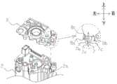
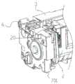
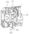
图8是本实用新型实施例2中驱动侧的局部结构示意图;Fig. 8 is the partial structure schematic diagram of the drive side in
图9是本实用新型实施例2中驱动侧的分解结构示意图;9 is a schematic diagram of the exploded structure of the drive side in
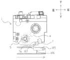
图10是本实用新型实施例2中力接收组件的分解结构示意图;10 is a schematic diagram of an exploded structure of the force receiving assembly in
图11是本实用新型实施例2中力接收部件的局部结构示意图;Fig. 11 is the partial structure schematic diagram of the force receiving part in the second embodiment of the present utility model;
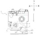
图12是本实用新型实施例2中力接收组件与施力部件配合的第一状态示意图;12 is a schematic diagram of the first state of the cooperation between the force receiving component and the force applying component in
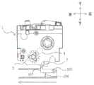
图13是本实用新型实施例2中力接收组件与施力部件配合的第二状态示意图;13 is a schematic diagram of the second state of the cooperation between the force receiving component and the force applying component in
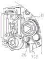
图14是本实用新型实施例3中力接收组件的局部结构示意图;14 is a schematic diagram of a partial structure of the force receiving assembly in
图15是本实用新型实施例3中力接收构件处的分解结构示意图;15 is a schematic diagram of the exploded structure of the force receiving member in
图16是本实用新型实施例3中力接收构件与施力构件配合的过程示意图;16 is a schematic diagram of the process of the cooperation between the force-receiving member and the force-applying member in
图17是本实用新型实施例3中力接收构件与粉仓主体之间增加弹性构件的结构示意图。17 is a schematic structural diagram of adding an elastic member between the force receiving member and the main body of the powder bin in
具体实施方式:Detailed ways:
为了使本实用新型实施例的目的,技术方案和技术效果更加清楚,下面将结合附图对本实用新型显影单元的技术方案进行清楚、完整地描述。显然,描述的实 施例仅仅是本实用新型的一个较佳实施例,而不是全部实施例,基于本实用新型的实施例,本领域技术人员在没有付出创造性劳动而获得的其它实施例,都属于本实用新型的保护范围。In order to make the purposes, technical solutions and technical effects of the embodiments of the present invention clearer, the technical solutions of the developing unit of the present invention will be clearly and completely described below with reference to the accompanying drawings. Obviously, the described embodiment is only a preferred embodiment of the present invention, rather than all embodiments. Based on the embodiments of the present invention, other embodiments obtained by those skilled in the art without creative work belong to The scope of protection of the utility model.
实施例1Example 1
如图2所示,为本实用新型实施例中处理盒1的结构示意图。处理盒1包括:显影单元2,包括显影框架,其内容纳有显影辊4;鼓单元3,包括鼓框架,容纳有感光鼓5;驱动力接收构件9,设置在处理盒1的纵向一侧,可接收成像设备传递的动力而带动显影辊4旋转;边盖6,与驱动力接收构件9设置在处理盒1的同一侧,支撑显影单元2和鼓单元3的一端;力接收构件7,设置在显影单元2上,可接收外力而推动显影单元2旋转,使得显影单元2中的显影辊4与鼓单元3中的感光鼓5分离。As shown in FIG. 2 , it is a schematic structural diagram of the process cartridge 1 in the embodiment of the present invention. The process cartridge 1 includes: a developing
如图3所示,为本实施例中处理盒1在设置有边盖6的一侧的分解结构示意图。本实施例将处理盒1在设置有驱动力接收构件9的一侧定义为驱动侧。显影框架包括边盖6、端盖8、护盖10和粉仓主体等。其中,端盖8、驱动力接收构件9以及护盖10都设置在显影单元2的驱动侧,具体的,端盖8固定至显影单元2的粉仓主体的一侧,驱动力接收构件9安装在端盖8上,护盖10套接着驱动力接收构件9并与端盖8相结合,且护盖10穿过边盖6上形成的通孔6a而被边盖6所支撑。本实施例中,力接收构件7具体设置在端盖8上,可选择的,也可将力接收构件7设置在护盖10上,或可将力接收构件7设置在显影单元2的框架上,只需满足力接收构件7接收外力后推动显影单元2旋转即可。为了便于下文描述,下面简要定义在本实施例中描述的方向,将处理盒1安装至成像设备中的重力方向定义为上下方向,处理盒1的纵向方向定义为前后方向,同时垂直于上下方向和左右方向的方向称为左右方向。As shown in FIG. 3 , a schematic diagram of an exploded structure of the process cartridge 1 on the side provided with the
如图4所示,为本实施例中力接收构件7、端盖8和显影单元2的框架相互装配的示意图。其中,力接收构件7可活动地安装至端盖8上,具体的,端盖8上形成有第一限制部8a和第二限制部8b,第一限制部8a和第二限制部8b之间形成大致“倒八字”形状的容纳开口8c,力接收构件7两侧抵接着第一限制部8a和第二限制部8b而安置在容纳开口8c中,并可在容纳开口8c中上下移动。需要说明的是,本实施例中力接收构件7的第一侧面7b和第二侧面7c分别抵接着第一限制部8a、第二限制部8b,且第一侧面7b为一竖直面,第二侧面7c为一斜平面。当力接收构件7沿容纳开口8c向下移动时,由于容纳开口8c自上而下越来越窄(即第一限制部8a与第二限制部8b之间的距离越来越小),力接收构件7在容纳开口8c中的可活动空间逐渐变小,第一限制部8a、第二限制部8b逐渐夹紧力接收构件7而限制力接收构件7在容纳开口8c中的活动量(晃动量);当力接收构件7沿容纳开口8c向上移动时,由于容纳开口8c自下而上越来越宽(即第一限制部8a与第二限制部8b之间的距离越来越大),力接收构件7在容纳开口8c中的可活动空间逐渐变大,力接收构件7在容纳开口8c中的活动量(晃动量)也会变大。还需说明的是,本实施例中力接收构件7的第一侧面7b和第二侧面7c与第一限制部8a、第二限制部8b之间的接触面是光滑的,即第一侧面7b和第二侧面7c与第一限制部8a、第二限制部8b之间的摩擦力很小,当力接收构件7在容纳开口8c中上下移动时,力接收构件7只需很小的向上作用力即可在容纳开口8c中向上移动,且力接收构件7由于自身重力即可在容纳开口8c中向下移动。As shown in FIG. 4 , it is a schematic diagram of the mutual assembly of the frame of the
可选择的,第一限制部8a还可以用于防止力接收构件7在接收施力构件105的分离力后相对于显影单元的框架发生旋转。具体的,在第一限制部8a上设置有一个朝向容纳力接收构件7的容纳部突出的突出部,该突出部设置为当力接收构件7接收外力而带动显影单元相对于鼓单元旋转时防止力接收构件7在容纳部滑动和松脱。Alternatively, the first restricting portion 8a may also serve to prevent the
本实施例中,力接收构件7上形成有一通孔7a,显影单元2的框架上形成有突起2a,当安置有力接收构件7的端盖8装配至显影单元2的框架上时,突起2a穿过力接收构件7的通孔7a而限制力接收构件7在容纳开口8c中的上下移动量,如此,力接收构件7不会从容纳开口8c中脱离。In this embodiment, a through hole 7a is formed on the
下面结合附图具体说明本实施例中力接收构件7与成像设备中的施力构件105配合而使显影辊4与感光鼓5相互分离的过程。The process in which the
为了便于描述,将力接收构件7向下移动至一个可接收施力构件105的力的位置称为分隔力接收位置,将力接收构件7从上述分隔力接收位置向上移动至一个更靠上的位置称为撤回位置,力接收构7可在分隔力接收位置和撤回位置之间移动。如图5所示,为本实施例中处理盒1安装至成像设备中的示意图。当处理盒1向下安装至成像设备中时,处理盒1的力接收构件7与成像设备中施力构件105的突起部107相接触,由于力接收构件7是可活动地安装在端盖8上的,且只需一很小的向上作用力即可向上移动,因此施力构件105的突起部107可迫推力接收构件7向上移动至撤回位置,可以理解的是,成像设备中施力构件105是被弹簧106所支撑的,力接收构件7在弹簧106弹力作用下即可向上移动。此时,处理盒1的显影辊4与感光鼓5处于相互接触状态。For ease of description, moving the
如图6所示,为本实施例中处理盒1在成像设备中的第一状态示意图。当处理盒1已安装至成像设备中时,成像设备中的施力构件105向左移动,施力构件105的突起部107越过力接收构件7,即施力构件105在上下方向不再抵接着力接收构件7,施力构件105移动至力接收构件7的左侧位置,力接收构件7在自身重力作用下向下移动至分隔力接收位置,力接收构件7被第一限制部8a、第二限制部8b逐渐夹紧。此时,处理盒1的显影辊4与感光鼓5处于相互接触状态。As shown in FIG. 6 , it is a schematic diagram of the first state of the process cartridge 1 in the image forming apparatus in this embodiment. When the process cartridge 1 has been installed in the image forming apparatus, the urging
如图7所示,为本实施例中处理盒1在成像设备中的第二状态示意图。成像设备中的施力构件105向右移动,施力构件105的突起部107抵接力接收构件7的第一侧面7b,此时,第一侧面7b作为受力面,具体的将力接收构件7的第一侧面7b构造为在重力方向上延伸的一竖直面,施力构件105通过突起部107挤压第一侧面7b而向力接收构件7施加向右作用力,力接收构件7进而带动显影单元2旋转,显影辊4与感光鼓5逐渐分离。在该过程中,力接收构件7被第一限制部8a、第二限制部8b所夹紧,即使施力构件105在推动力接收构件7旋转的过程中产生向上作用力,力接收构件7也不会向上移动,始终保持与施力构件105的突起部107相互抵接的状态,使得处理盒1维持在显影辊4与感光鼓5相互分离状态。As shown in FIG. 7 , it is a schematic diagram of the second state of the process cartridge 1 in the image forming apparatus in this embodiment. The force-applying
优选的,为了使得力接收构件7可以更加顺畅的下移到力接收位置,也可在力接收构件7的上端连接一弹性构件,通过弹性构件向力接收构件7施加的向下弹性力迫使力接收构件7从撤回位置下移到力接收位置,如此可保持力接收构件7始终处于竖直位置,防止由于晃动等因素导致力接收构件7被卡在撤回位置。且该弹性构件向力接收构件7施加的向下弹性力小于弹簧106向施力构件105施加的向上弹性力,使得力接收构件7在施力构件105的作用下可向上移动至撤回位置。Preferably, in order to make the
优选的,为了使得力接收构件7与施力构件105配合并接收分隔力时更加稳定,在力接收构件7的受力面即第一侧面7b上设置一个防滑构件,具体的可以设置为一个海绵,海绵贴在该第一侧面7b上,突起部107在抵接上述海绵时,可以压迫海绵变形,突起部107与海绵接触的地方海绵会被压缩而自动凹入形成一个凹口,当突起部107在迫推力接收构件7移动时,由于突起部107与海绵上由于变形而形成的凹口配合不容易打滑,使得力接收构件7接收施力构件105的分隔力时更加稳定。防滑构件除了设置为为海绵也可以设置为其他形式,例如软性的塑胶和硅胶等。Preferably, in order to make the force-receiving
需要说明的是,在本实施例的描述中,术语“向上”、“向下”并不是指示或暗示所指的装置或元件必须具有的特定方位,即不仅仅指在竖直方向的“向上”、“向下”,可以理解的是,也可解释为相对竖直方向倾斜一定角度的“斜向上”、“斜向下”,在处理盒向成像设备中安装的过程中,力接收构件7的移动方式可以总结为:当处理盒安装至成像设备中时,力接收构件7可被施力构件105迫推而至少在重力方向上向上移动。It should be noted that, in the description of this embodiment, the terms "upward" and "downward" do not indicate or imply the specific orientation that the referred device or element must have, that is, not only refer to "upward" in the vertical direction ” and “downward”, it can be understood that it can also be interpreted as “oblique upward” and “slanted downward” inclined at a certain angle relative to the vertical direction. During the process of installing the process cartridge into the imaging device, the force receiving member The moving manner of 7 can be summarized as follows: when the process cartridge is mounted in the image forming apparatus, the
实施例2Example 2
接下来介绍本发明实施例2,如图8至图10所示,本发明实施例2中力接收构件7的移动方向和与成像设备中施力构件105的预啮合位置与实施例1中不同。Next, the second embodiment of the present invention will be described. As shown in FIGS. 8 to 10 , the moving direction of the
本实施例中,力接收组件20包括力接收构件701和用于控制力接收构件701移动的控制装置。控制装置包括力接收杆21、控制杆22、回位弹簧23以及偏置构件24。受力杆21可与设置在护盖10中的肋板10a抵接以限制受力杆21在接收力时向显影单元2内侧移动,具体的,受力杆21的一侧端可抵接在肋板10a上。受力杆21的一个末端和控制杆22的一个末端活动连接,具体的,在受力杆21的一侧端设置有一个突出柱21a,在控制杆22的一端设置有与该突出柱21a匹配的孔22a,通过将该突出柱21a插入该孔22a中,控制杆22和受力杆21两者之间可相互旋转。在控制杆22上还设置有一个拉钩22b,在护盖10上也设置有拉钩10c,通过将回位弹簧23的两端分别勾住拉钩22b和10c,再结合肋板10a对受力杆21的阻挡作用,可以将受力杆21和控制杆22保持在一个初始位置,在该初始位置受力杆21的至少一部分是突出于显影单元框架的,该突出的部分用于接收外力。在护盖10上设置有一个安装孔10b,控制杆22上设置有一个圆形突柱22c卡入该安装孔10b中,控制杆22可以该圆形突柱22c和安装孔10b的结合部为支点旋转。在控制杆22的另一端设置有施力部22d,用于对力接收构件701施力。显影单元2的粉仓主体11上临近力接收构件701的位置设置有沿显影单元2的纵向方向上延伸的突出导向柱11a,力接收构件701上设置有与该突出导向柱11a匹配的滑动槽701c,滑动槽701c可沿着突出导向柱11a滑动。在护盖10和和力接收构件701之间设置的偏置构件24用于在显影单元的纵向方向上迫推力接收构件701至一个偏置位置。将力接收构件701的施力端22d设置有施力面22d1,力接收构件701上设置有被迫推面701a,当控制杆22绕着圆形突出柱22c旋转时,施力面22d1通过迫推被迫推面701a可迫推所述力接收构件701在显影单元的纵向方向上移动。In this embodiment, the
下面结合图12至图13说明本实施例中,力接收构件701与成像设备中的施力构件105啮合并接收分离力的过程。The process in which the
当处理盒安装入成像设备中,在显影单元的纵向方向,将力接收构件701的偏置位置设置成与成像设备中的施力构件105不重叠,因此,处理盒可以正常沿着与显影单元纵向方向垂直的左右方向顺畅安装入成像设备中,随着成像设备中的门盖的合上动作,设置在处理盒上的力接收组件20可接收成像设备中外力,具体的是成像设备中的内壁对受力杆21施加压力,受力杆21和控制杆22一同开始受力,由于受力杆21被肋板10a阻挡,因此控制杆22开始绕着圆形突出柱22c旋转,并通过施力面22d1操作力接收构件701向靠近成像设备中的施力构件105移动,此时,在显影单元的纵向方向上,施力构件105和力接收构件701的至少一部分是相互重叠的,因此,力接收构件701被施力构件105阻挡而停止在施力构件105的一侧,此时,控制杆22被来自成像设备内壁的力挤压而具有一定的变形量,当成像设备预转并驱动施力构件105向左移动(参见图6)时,在显影单元的纵向方向,施力构件105将会与力接收构件701解除重叠状态,利用控制杆22的弹性恢复可以迫使力接收构件701在纵向方向上继续移动一定行程使得施力构件105与力接收构件107在左右方向上重叠,力接收构件107可以接收施力构件105的分离力使得显影辊与感光鼓分离。当需要取出盒子时,随着成像设备中的门盖的开启,成像设备取消对力接收组件20的力,在回位弹簧23的弹力作用下,控制杆22沿着相反方向旋转回到预设的初始位置,控制杆22取消对力接收构件701的按压力,力接收构件701在偏置构件24的偏置力下回到偏置位置,处理盒可以顺畅取出。When the process cartridge is installed in the image forming apparatus, in the longitudinal direction of the developing unit, the offset position of the
实施例3Example 3
接下来,接收本实用新型实施例3。本实施例中,将力接收构件702设置成可旋转移动的结构。Next, the third embodiment of the present invention is received. In this embodiment, the
如图14和图15所示,粉仓主体11上设置有一个安装孔11b,力接收构件702上设置有可安装入所述安装孔11b内的旋转支撑部702a,力接收构件702通过旋转支撑部702a插入安装孔11b中可以相对于粉仓主体11旋转。在力接收构件702的分隔力接收一侧的侧面还贴有一个防滑构件7021,优选的,该防滑构件7021构造为海绵。As shown in Fig. 14 and Fig. 15 , a mounting
如图16中(a)至(c)所示,当处理盒初始安装入成像设备中,随着成像设备的门盖的闭合,力接收构件702初始位于成像设备中的施力构件105的左侧,此时,力接收构件702可以处于一个与施力构件105分隔的位置,也可以与施力构件105有接触并被施力构件105压迫而向上旋转一定角度,随着成像设备的预转,施力构件105开始从右向左移动,在施力构件105从右向左移动的过程中,会迫推力接收构件702向上旋转,施力构件105越过向上旋转后的力接收构件702,最终如图16中(c)所示,施力构件105的施力部在力接收构件702的左侧,力接收构件702将会在自身重力的作用下向下旋转回到图16中(a)中位置,并与防滑构件7021接触,此位置时力接收构件702可以接收施力构件105的间隔力,当施力构件105被成像设备控制从图16中(c)中位置从左向右移动时,通过施力构件105对力接收构件702施加力使得显影辊与感光鼓分隔开。此种设置,可以使得力接收构件702被施力构件105迫推时更容易向上移动而避开与施力构件105的干涉。As shown in (a) to (c) of FIG. 16 , when the process cartridge is initially installed in the image forming apparatus, with the closing of the door cover of the image forming apparatus, the
优选的,为了使得力接收构件702在向上旋转后可以更加灵活的回到一个可以接收施力构件105的分隔力的力接收位置,可以在力接收构件702和粉仓主体11之间设置一个弹性构件26,利用弹性构件26的弹性力辅助力接收构件702向下旋转回到力接收位置。Preferably, in order to make the force-receiving
以上各实施例中,力接收构件的移动方式可以总结为如下,力接收构件相对于显影框架具有一个可与成像设备中的施力构件接触并接收使得显影辊与感光鼓分离的间隔力的间隔力接收位置,以及一个与间隔力接收位置不同的避让位置,具体的,在上述避让位置和间隔力接收位置,力接收构件接收所述施力构件的分隔力的力接收部相对于与显影框架具有不同的位置,该不同的位置可以是在处理盒的纵向方向上的不同位置,也可以是在处理盒上下方向,也可以是同时在处理盒的纵向方向和上下方向都具有不同的位置,只要满足,在间隔力接收位置力接收构件可以与施力构件接触并接收分隔显影辊和感光鼓的力,在避让位置时允许施力构件可以自由左右移动即可。另外,由于在处理盒的驱动侧具有驱动力接收构件9,当驱动力接收构件9接收成像设备中的驱动力旋转时会产生一个大的扭矩使得显影辊靠近感光鼓,即使现有技术中在该驱动力接收构件9与显影单元中增阿离合结构也会产品一个扭矩,因此,将力接收构件702设置在处理盒的驱动侧可以用里一个较小的分隔力以克服上述使得显影辊靠近感光鼓的扭矩。In each of the above embodiments, the moving manner of the force receiving member can be summarized as follows, the force receiving member has an interval relative to the developing frame that can contact the force applying member in the image forming apparatus and receive an interval force that separates the developing roller from the photosensitive drum The force receiving position, and an escape position different from the spacer force receiving position, specifically, in the above-mentioned avoidance position and spacer force receiving position, the force receiving portion of the force receiving member receiving the spacer force of the force applying member is relative to the developing frame. have different positions, and the different positions can be different positions in the longitudinal direction of the process cartridge, or in the up and down direction of the process cartridge, or have different positions in both the longitudinal direction and the up and down direction of the process cartridge at the same time, As long as it is satisfied, the force receiving member can contact the urging member at the spaced force receiving position and receive the force separating the developing roller and the photosensitive drum, and the urging member can freely move left and right at the avoidance position. In addition, since the driving
与现有技术相比,本实用新型实施例中处理盒的力接收构件在上下方向是可自由活动的,而在左右方向是被限制活动的,因此,当处理盒安装进成像设备中时,力接收构件可移动至与成像设备中的施力构件不相干涉的位置;当成像设备中的施力构件左右移动时,力接收构件可与施力构件配合使得处理盒的显影辊与感光鼓相互分离。解决了现有技术中成像设备中的施力构件在推动显影单元旋转时容易出现卡死的技术问题。Compared with the prior art, in the embodiment of the present invention, the force receiving member of the process cartridge is freely movable in the up-down direction, but restricted in the left-right direction. Therefore, when the process cartridge is installed in the image forming apparatus, The force receiving member can be moved to a position that does not interfere with the force applying member in the image forming apparatus; when the force applying member in the image forming apparatus moves left and right, the force receiving member can cooperate with the force applying member so that the developing roller of the process cartridge and the photosensitive drum separated from each other. The technical problem that the force-applying member in the prior art image forming apparatus is likely to be stuck when pushing the developing unit to rotate is solved.
以上实施例仅用以说明本实用新型的技术方案,而非对其限制;尽管参照前述实施例对本实用新型进行了详细的说明,本领域的普通技术人员应当理解:其依然可以对前述各实施例所记载的技术方案进行修改,或者对其中部分技术特征进行等同替换;而这些修改或者替换,并不使相应技术方案的本质脱离本实用新型各实施例技术方案的精神和范围。The above embodiments are only used to illustrate the technical solutions of the present utility model, but not to limit them; although the present utility model has been described in detail with reference to the foregoing embodiments, those of ordinary skill in the art should understand that: it can still be used for the foregoing implementations. The technical solutions described in the examples are modified, or some technical features thereof are equivalently replaced; and these modifications or replacements do not make the essence of the corresponding technical solutions deviate from the spirit and scope of the technical solutions of the embodiments of the present invention.
Claims (10)
Translated fromChineseApplications Claiming Priority (4)
| Application Number | Priority Date | Filing Date | Title |
|---|---|---|---|
| CN2019200855084 | 2019-01-18 | ||
| CN201920085508 | 2019-01-18 | ||
| CN201920164202 | 2019-01-30 | ||
| CN2019201642028 | 2019-01-30 |
Publications (1)
| Publication Number | Publication Date |
|---|---|
| CN211653402Utrue CN211653402U (en) | 2020-10-09 |
Family
ID=71683158
Family Applications (2)
| Application Number | Title | Priority Date | Filing Date |
|---|---|---|---|
| CN202020099178.7UWithdrawn - After IssueCN211653402U (en) | 2019-01-18 | 2020-01-17 | Processing box |
| CN202010050284.0AActiveCN111459002B (en) | 2019-01-18 | 2020-01-17 | Processing box |
Family Applications After (1)
| Application Number | Title | Priority Date | Filing Date |
|---|---|---|---|
| CN202010050284.0AActiveCN111459002B (en) | 2019-01-18 | 2020-01-17 | Processing box |
Country Status (1)
| Country | Link |
|---|---|
| CN (2) | CN211653402U (en) |
Cited By (3)
| Publication number | Priority date | Publication date | Assignee | Title |
|---|---|---|---|---|
| CN111459002A (en)* | 2019-01-18 | 2020-07-28 | 江西亿铂电子科技有限公司 | Processing box |
| US11112749B1 (en) | 2020-06-30 | 2021-09-07 | Jiangxi Yibo E-Tech Co. Ltd. | Process cartridge |
| WO2025102407A1 (en)* | 2023-11-14 | 2025-05-22 | 珠海美景联合科技有限公司 | Process cartridge |
Families Citing this family (1)
| Publication number | Priority date | Publication date | Assignee | Title |
|---|---|---|---|---|
| US12140902B2 (en) | 2020-08-15 | 2024-11-12 | Zhuhai Dinglong Huitong Print Technology Co., Ltd. | Process cartridge |
Family Cites Families (12)
| Publication number | Priority date | Publication date | Assignee | Title |
|---|---|---|---|---|
| JP4280770B2 (en)* | 2006-01-11 | 2009-06-17 | キヤノン株式会社 | Process cartridge and electrophotographic image forming apparatus |
| JP4458377B2 (en)* | 2007-06-29 | 2010-04-28 | キヤノン株式会社 | Process cartridge and electrophotographic image forming apparatus |
| JP5121573B2 (en)* | 2008-05-27 | 2013-01-16 | キヤノン株式会社 | Process cartridge and image forming apparatus |
| JP4775504B2 (en)* | 2010-11-25 | 2011-09-21 | ブラザー工業株式会社 | Cartridge and image forming apparatus |
| JP2013130711A (en)* | 2011-12-21 | 2013-07-04 | Canon Inc | Process cartridge |
| JP6202911B2 (en)* | 2012-09-07 | 2017-09-27 | キヤノン株式会社 | Image forming apparatus, process cartridge |
| CN204731529U (en)* | 2015-06-23 | 2015-10-28 | 江西镭博钛电子科技有限公司 | A kind of handle box |
| CN204790320U (en)* | 2015-07-14 | 2015-11-18 | 江西镭博钛电子科技有限公司 | Processing box |
| CN205121159U (en)* | 2015-07-21 | 2016-03-30 | 江西镭博钛电子科技有限公司 | Processing case |
| CN207601519U (en)* | 2016-11-07 | 2018-07-10 | 纳思达股份有限公司 | A kind of handle box and electronic imaging apparatus |
| CN108241269B (en)* | 2016-12-24 | 2024-05-14 | 江西亿铂电子科技有限公司 | Developing unit and processing box including the developing unit |
| CN211653402U (en)* | 2019-01-18 | 2020-10-09 | 江西亿铂电子科技有限公司 | Processing box |
- 2020
- 2020-01-17CNCN202020099178.7Upatent/CN211653402U/ennot_activeWithdrawn - After Issue
- 2020-01-17CNCN202010050284.0Apatent/CN111459002B/enactiveActive
Cited By (4)
| Publication number | Priority date | Publication date | Assignee | Title |
|---|---|---|---|---|
| CN111459002A (en)* | 2019-01-18 | 2020-07-28 | 江西亿铂电子科技有限公司 | Processing box |
| CN111459002B (en)* | 2019-01-18 | 2024-12-17 | 江西亿铂电子科技有限公司 | Processing box |
| US11112749B1 (en) | 2020-06-30 | 2021-09-07 | Jiangxi Yibo E-Tech Co. Ltd. | Process cartridge |
| WO2025102407A1 (en)* | 2023-11-14 | 2025-05-22 | 珠海美景联合科技有限公司 | Process cartridge |
Also Published As
| Publication number | Publication date |
|---|---|
| CN111459002A (en) | 2020-07-28 |
| CN111459002B (en) | 2024-12-17 |
Similar Documents
| Publication | Publication Date | Title |
|---|---|---|
| CN211653402U (en) | Processing box | |
| CN2829304Y (en) | Open-close mechanism and image recorder with the mechanism | |
| JP5223210B2 (en) | Image forming apparatus | |
| CN204731529U (en) | A kind of handle box | |
| US11940755B2 (en) | Process cartridge with movable force receiving portion configured to separate developing roller and photosensitive drum | |
| RU2009129002A (en) | TECHNOLOGICAL CARTRIDGE AND ELECTROPHOTOGRAPHIC DEVICE FOR IMAGE FORMATION | |
| CN204790320U (en) | Processing box | |
| CN1735328A (en) | Image recording apparatus and opening and closing mechanism | |
| CN205121159U (en) | Processing case | |
| JP2020166090A5 (en) | ||
| JP3128796U (en) | Drive roller attachment mechanism for paper transport device | |
| CN219958076U (en) | Processing box | |
| JP2007298616A (en) | Contact/separation unit and image forming apparatus | |
| JP2018103410A (en) | Image forming apparatus | |
| CN220438759U (en) | Process cartridge and image forming apparatus | |
| CN104570676A (en) | Image forming apparatus and maintenance method thereof | |
| CN219039575U (en) | Process cartridge | |
| US20110241511A1 (en) | Opening and closing apparatus | |
| CN216387748U (en) | Developing box | |
| EP4198637A1 (en) | Process cartridge | |
| JP5124011B2 (en) | Seat pickup module | |
| KR100310130B1 (en) | A process cartridge having a shutter to cover surface of photoconductor and image forming apparatus using same cartridge | |
| JP2006023325A (en) | Original cover opening/closing device | |
| CN218974785U (en) | Processing box | |
| CN221884118U (en) | Powder box and imaging equipment |
Legal Events
| Date | Code | Title | Description |
|---|---|---|---|
| GR01 | Patent grant | ||
| GR01 | Patent grant | ||
| AV01 | Patent right actively abandoned | Granted publication date:20201009 Effective date of abandoning:20241217 | |
| AV01 | Patent right actively abandoned | Granted publication date:20201009 Effective date of abandoning:20241217 | |
| AV01 | Patent right actively abandoned | ||
| AV01 | Patent right actively abandoned |