CN211634085U - Double-arm electric tower crane - Google Patents
Double-arm electric tower craneDownload PDFInfo
- Publication number
- CN211634085U CN211634085UCN201922347107.4UCN201922347107UCN211634085UCN 211634085 UCN211634085 UCN 211634085UCN 201922347107 UCN201922347107 UCN 201922347107UCN 211634085 UCN211634085 UCN 211634085U
- Authority
- CN
- China
- Prior art keywords
- support
- movable arm
- tower crane
- support column
- support frame
- Prior art date
- Legal status (The legal status is an assumption and is not a legal conclusion. Google has not performed a legal analysis and makes no representation as to the accuracy of the status listed.)
- Expired - Fee Related
Links
Images


Landscapes
- Accommodation For Nursing Or Treatment Tables (AREA)
Abstract
Description
Translated fromChinese技术领域technical field
本实用新型涉及一种双臂电动吊塔,属于医疗机械技术领域。The utility model relates to a double-arm electric pendant, which belongs to the technical field of medical machinery.
背景技术Background technique
电动吊塔是现代手术室常用的一种新型实用的医疗辅助设备,能电动升降一定高度,又能在一定直径范围内旋转,可根据医护人员要求,移动和锁定塔体位置;必备的医用气体、负压吸引、强弱电、网络输出终端集中在平台功能箱上,平台可承载一定重量的医疗仪器,给医护人员带来了方便,提高了手术成功率;现有的电动吊塔一般都是单臂的,灵活性不够;且臂比较短,不够安全等的因素,不能在手术中起到很好地作用;且目前使用的双臂吊塔移动不便,且活动臂多为人工驱动,长期使用时,尤其是两个活动壁的连接处由于不停受力而导致阻尼力变差,不能很好的固定活动臂,因此需要一种双臂电动吊塔。The electric pendant is a new type of practical medical auxiliary equipment commonly used in modern operating rooms. It can be electrically lifted and lowered to a certain height and can be rotated within a certain diameter range. It can move and lock the position of the tower body according to the requirements of medical staff. Gas, negative pressure suction, strong and weak current, and network output terminals are concentrated on the platform function box. The platform can carry a certain weight of medical instruments, which brings convenience to medical staff and improves the success rate of surgery; the existing electric pendant is generally They are all single-armed and not flexible enough; and the arms are relatively short and not safe enough, so they cannot play a good role in surgery; and the currently used double-arm pendant is inconvenient to move, and the movable arms are mostly driven manually. , When used for a long time, especially the damping force of the connection of the two movable walls is deteriorated due to the continuous force, and the movable arm cannot be fixed well, so a double-arm electric pendant is required.
实用新型内容Utility model content
本实用新型要解决的技术问题克服现有的缺陷,提供一种双臂电动吊塔,通过设置两条活动臂,增加吊塔的使用范围,并在且活动臂使用电机驱动,指向精准,便于调节,可以有效解决背景技术中的问题。The technical problem to be solved by the utility model overcomes the existing defects, and provides a double-arm electric pendant. By setting two movable arms, the use range of the pendant is increased, and the movable arm is driven by a motor, and the pointing is accurate and convenient. Adjustment can effectively solve the problems in the background technology.
为了解决上述技术问题,本实用新型提供了如下的技术方案:In order to solve the above-mentioned technical problems, the utility model provides the following technical solutions:
一种双臂电动吊塔,包括底座,所述底座下方连接有万向轮,所述底座上方一侧设有支撑架,所述支撑架下方设有抽屉,所述抽屉上方位于所述支撑架之间设有托盘,所述支撑架一侧设有支撑柱,所述支撑柱内部设有液压缸,所述液压缸内部连接有液压杆,所述液压杆上方贯穿于所述支撑柱内壁,所述液压杆外部一侧位于所述支撑柱上方设有密封环,所述液压杆顶端连接第一支座,所述第一支座嵌入连接于第一活动臂内部一侧,所述第一活动臂内部设有电机,所述电机输出端连接有锥形齿轮一,所述锥形齿轮一与锥形齿轮二啮合,所述锥形齿轮二上方设有传动轴,所述传动轴顶端连接第二支座,所述第二支座嵌入连接于第二活动臂内部,所述第二活动臂内部一侧设有小型液压缸,所述小型液压缸内部设有小型液压杆,所述小型液压杆顶端连接基座。A double-arm electric pendant comprises a base, a universal wheel is connected under the base, a support frame is arranged on one side above the base, a drawer is arranged under the support frame, and the drawer is located above the support frame A tray is arranged between them, a support column is arranged on one side of the support frame, a hydraulic cylinder is arranged inside the support column, a hydraulic rod is connected inside the hydraulic cylinder, and the upper part of the hydraulic rod penetrates the inner wall of the support column, The outer side of the hydraulic rod is provided with a sealing ring above the support column, the top end of the hydraulic rod is connected to a first support, the first support is embedded and connected to the inner side of the first movable arm, and the first support There is a motor inside the movable arm, the output end of the motor is connected with a
作为本实用新型的一种优选技术方案,所述支撑柱一侧设有卡座,所述卡座内部铰接有支杆,所述支杆在所述卡座上转动连接,所述支杆外部上方卡接有滑块,所述滑块顶端设有输液支架。As a preferred technical solution of the present invention, one side of the support column is provided with a card seat, the inside of the card seat is hinged with a support rod, the support rod is rotatably connected on the card seat, and the outside of the support rod is The upper part is clamped with a slider, and the top of the slider is provided with an infusion support.
作为本实用新型的一种优选技术方案,所述输液支架为可升降支架,所述输液支架一侧设有转盘,所述支杆上设有与所述滑块相匹配的T型滑轨,所述滑块在所述支杆上滑动连接。As a preferred technical solution of the present invention, the infusion support is a liftable support, a turntable is provided on one side of the infusion support, and a T-shaped slide rail matched with the slider is provided on the support rod. The slider is slidably connected on the support rod.
作为本实用新型的一种优选技术方案,所述万向轮上设有固定踏板,所述托盘数量为两个,分别设置与所述支撑架内部上下两侧,所述抽屉上设有拉手。As a preferred technical solution of the present invention, the universal wheel is provided with a fixed pedal, the number of the trays is two, which are respectively arranged on the upper and lower sides of the support frame, and the drawer is provided with a handle.
作为本实用新型的一种优选技术方案,所述第一活动臂在所述第一支座上转动连接。As a preferred technical solution of the present invention, the first movable arm is rotatably connected on the first support.
作为本实用新型的一种优选技术方案,所述第二活动臂通过所述传动轴与所述第二支座在所述第一活动臂上转动连接。As a preferred technical solution of the present invention, the second movable arm is rotatably connected with the second support on the first movable arm through the transmission shaft.
本实用新型的技术效果和优点:Technical effects and advantages of the present utility model:
1、本实用新型在需要调节第一活动臂与第二活动臂的高度时,启动液压缸,液压缸推动液压杆向上移动,从而使第一支座推动第一活动臂与第二活动臂向上移动,当调整至需要使用的高度时,关闭液压缸,从而调节好第一活动臂与第二活动臂的使用高度。1. When the height of the first movable arm and the second movable arm needs to be adjusted, the hydraulic cylinder is activated, and the hydraulic cylinder pushes the hydraulic rod to move upward, so that the first support pushes the first movable arm and the second movable arm upward. Move, when adjusted to the required height, close the hydraulic cylinder, so as to adjust the use height of the first movable arm and the second movable arm.
2、本实用新型在需要转动第一活动臂与第二活动臂时,打开电机电源,启动电机,电机转动时,带动锥形齿轮一转动,锥形齿轮一带动锥形齿轮二与传动轴转动,从而调节第二活动臂的使用位置,在第二活动臂调节完成后,启动小型液压缸,小型液压缸推动小型液压杆向上移动,从而将基座固定在天花板上。2. When the utility model needs to rotate the first movable arm and the second movable arm, turn on the motor power and start the motor. When the motor rotates, it drives the
3、本实用新型当需要对病人进行输液时,拉动输液支架,使滑块在支杆上移动,移动至合适位置后,拧松转盘,调节输液支架的输液高度,调节完成后,拧紧转盘将输液支架的高度固定,然后对病人进行输液治疗。3. In the present invention, when the patient needs to be infused, the infusion support is pulled to move the slider on the support rod. After moving to a suitable position, the turntable is loosened to adjust the infusion height of the infusion support. After the adjustment is completed, tighten the turntable to The height of the infusion stand is fixed, and then infusion therapy is performed on the patient.
附图说明Description of drawings
附图用来提供对本实用新型的进一步理解,并且构成说明书的一部分,与本实用新型的实施例一起用于解释本实用新型,并不构成对本实用新型的限制。The accompanying drawings are used to provide a further understanding of the present invention, and constitute a part of the specification, and are used to explain the present invention together with the embodiments of the present invention, and do not constitute a limitation to the present invention.
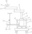
图1是本实用新型的主视图。Figure 1 is a front view of the present invention.
图2是本实用新型的剖视图。Figure 2 is a cross-sectional view of the present invention.
图3是本实用新型的滑块与支杆连接图。Fig. 3 is the connection diagram of the slider and the support rod of the present invention.
图4是本实用新型的a处区域放大图。FIG. 4 is an enlarged view of the region a of the present invention.
图中标号:1、底座;2、万向轮;3、支撑架;4、抽屉;5、托盘;6、支撑柱;7、液压缸;8、液压杆;9、密封环;10、第一支座;11、第一活动臂;12、电机;13、锥形齿轮一;14、锥形齿轮二;15、传动轴;16、第二支座;17、第二活动臂;18、小型液压缸;19、小型液压杆;20、基座;21、卡座;22、支杆;23、滑块;24、输液支架。Labels in the figure: 1, base; 2, universal wheel; 3, support frame; 4, drawer; 5, tray; 6, support column; 7, hydraulic cylinder; 8, hydraulic rod; 9, sealing ring; 10, the first A seat; 11, the first movable arm; 12, the motor; 13, the bevel gear one; 14, the bevel gear two; 15, the transmission shaft; 16, the second support; 17, the second movable arm; 18, Small hydraulic cylinder; 19, small hydraulic rod; 20, base; 21, cassette; 22, strut; 23, slider; 24, infusion stand.
具体实施方式Detailed ways
以下结合附图对本实用新型的优选实施例进行说明,应当理解,此处所描述的优选实施例仅用于说明和解释本实用新型,并不用于限定本实用新型。The preferred embodiments of the present utility model will be described below with reference to the accompanying drawings. It should be understood that the preferred embodiments described herein are only used to illustrate and explain the present utility model, but not to limit the present utility model.
如图1-图4所示,一种双臂电动吊塔,包括底座1,底座1下方连接有万向轮2,底座1上方一侧设有支撑架3,支撑架3下方设有抽屉4,抽屉4上方位于支撑架3之间设有托盘5,支撑架3一侧设有支撑柱6,支撑柱6内部设有液压缸7,液压缸7内部连接有液压杆8,液压杆8上方贯穿于支撑柱6内壁,液压杆8外部一侧位于支撑柱6上方设有密封环9,液压杆8顶端连接第一支座10,第一支座10嵌入连接于第一活动臂11内部一侧,第一活动臂11内部设有电机12,电机12输出端连接有锥形齿轮一13,锥形齿轮一13与锥形齿轮二14啮合,锥形齿轮二14上方设有传动轴15,传动轴15顶端连接第二支座16,第二支座16嵌入连接于第二活动臂17内部,第二活动臂17内部一侧设有小型液压缸18,小型液压缸18内部设有小型液压杆19,小型液压杆19顶端连接基座20。As shown in Figures 1-4, a double-arm electric pendant includes a
如图1、图2、图3所示,支撑柱6一侧设有卡座21,卡座21内部铰接有支杆22,支杆22在卡座21上转动连接,支杆22外部上方卡接有滑块23,滑块23顶端设有输液支架24,输液支架24为可升降支架,输液支架24一侧设有转盘,支杆22上设有与滑块23相匹配的T型滑轨,滑块23在支杆22上滑动连接,输液支架24可以通过滑块23在支杆22上移动,从而调节输液支架24的位置。As shown in FIGS. 1 , 2 and 3 , a
如图1、图2所示,万向轮2上设有固定踏板,托盘5数量为两个,分别设置与支撑架3内部上下两侧,抽屉4上设有拉手,万向轮2方本使用新型进行移动,托盘5可以放置医生使用的手术器械。As shown in Figures 1 and 2, the
如图2、图3所示,第一活动臂11在第一支座10上转动连接,第二活动臂17通过传动轴15与第二支座16在第一活动臂11上转动连接,第一活动臂11与第二活动臂17可以调节使用角度和使用范围,方便医生使用和操作。这里说明,液压缸、电机、小型液压缸均为现有技术,故而涉及其它的现有技术这里不再赘述。As shown in Figures 2 and 3, the first
为了方便理解本实用新型的上述技术方案,以下就本实用新型在实际过程中的工作原理或者操作方式进行详细说明。In order to facilitate the understanding of the above technical solutions of the present invention, the working principle or operation mode of the present invention in the actual process will be described in detail below.
在实际使用中:在需要调节第一活动臂11与第二活动臂17的高度时,启动液压缸7,液压缸7推动液压杆8向上移动,从而使第一支座10推动第一活动臂11与第二活动臂17向上移动,当调整至需要使用的高度时,关闭液压缸7,从而调节好第一活动臂11与第二活动臂17的使用高度;在需要转动第一活动臂11与第二活动臂17时,打开电机12电源,启动电机12,电机12转动时,带动锥形齿轮一13转动,锥形齿轮一13带动锥形齿轮二14与传动轴15转动,从而调节第二活动臂17的使用位置,在第二活动臂17调节完成后,启动小型液压缸18,小型液压缸18推动小型液压杆19向上移动,从而将基座20固定在天花板上;当需要对病人进行输液时,拉动输液支架24,使滑块23在支杆22上移动,移动至合适位置后,拧松转盘,调节输液支架24的输液高度,调节完成后,拧紧转盘从而将输液支架24的高度固定,然后对病人进行输液治疗。In actual use: when the height of the first
以上为本实用新型较佳的实施方式,本实用新型所属领域的技术人员还能够对上述实施方式进行变更和修改,因此,本实用新型并不局限于上述的具体实施方式,凡是本领域技术人员在本实用新型的基础上所作的任何显而易见的改进、替换或变型均属于本实用新型的保护范围。The above are the preferred embodiments of the present invention. Those skilled in the art can also make changes and modifications to the above-mentioned embodiments. Therefore, the present invention is not limited to the above-mentioned specific embodiments. Any obvious improvement, replacement or modification made on the basis of the present invention belongs to the protection scope of the present invention.
Claims (6)
Priority Applications (1)
| Application Number | Priority Date | Filing Date | Title |
|---|---|---|---|
| CN201922347107.4UCN211634085U (en) | 2020-08-28 | 2020-08-28 | Double-arm electric tower crane |
Applications Claiming Priority (1)
| Application Number | Priority Date | Filing Date | Title |
|---|---|---|---|
| CN201922347107.4UCN211634085U (en) | 2020-08-28 | 2020-08-28 | Double-arm electric tower crane |
Publications (1)
| Publication Number | Publication Date |
|---|---|
| CN211634085Utrue CN211634085U (en) | 2020-10-09 |
Family
ID=72698542
Family Applications (1)
| Application Number | Title | Priority Date | Filing Date |
|---|---|---|---|
| CN201922347107.4UExpired - Fee RelatedCN211634085U (en) | 2020-08-28 | 2020-08-28 | Double-arm electric tower crane |
Country Status (1)
| Country | Link |
|---|---|
| CN (1) | CN211634085U (en) |
- 2020
- 2020-08-28CNCN201922347107.4Upatent/CN211634085U/ennot_activeExpired - Fee Related
Similar Documents
| Publication | Publication Date | Title |
|---|---|---|
| CN207849108U (en) | A kind of LED shadowless lamps of automatic adjustment irradiating angle | |
| CN103027754A (en) | Automatic vertical support of close-range seed implantation robot | |
| CN211634085U (en) | Double-arm electric tower crane | |
| CN209437615U (en) | A portable straight leg raising trainer | |
| CN209172806U (en) | A kind of intelligence nurse station | |
| CN213157375U (en) | Device for adjusting limb angle in surgical operation | |
| CN214596399U (en) | An arm support frame for PICC maintenance | |
| CN215821149U (en) | Ablation catheter propulsion device | |
| CN219126497U (en) | Surgical thread fixing box | |
| CN113499103A (en) | Auxiliary sampling device for digestive system department and working mode thereof | |
| CN209847407U (en) | Fixing device for arm surgery | |
| CN109431611B (en) | A flexible three-arm surgical robot | |
| CN221635875U (en) | Auxiliary distraction device for cardiothoracic surgery | |
| CN211355783U (en) | Puncture needle for pediatric clinic | |
| CN209092326U (en) | A drainage device for medical cardiology | |
| CN221839646U (en) | Light supplementing illumination lamp for nursing of operating room nurses | |
| CN211188043U (en) | Auxiliary head frame for tracheal foreign body taking-out operation | |
| CN221578086U (en) | An out-of-home first aid treatment kit | |
| CN216417685U (en) | A kind of auxiliary vehicle for upper limb surgery in operating room | |
| CN219109981U (en) | A thoracic surgery nursing bandage winding device | |
| CN221618110U (en) | Hemodialysis conversion device | |
| CN221808051U (en) | A minimally invasive surgical robot | |
| CN221844820U (en) | Auxiliary device for minimally invasive hepatobiliary surgery | |
| CN206755023U (en) | A kind of operation shadowless lamp for being capable of voice regulation lamplight brightness | |
| CN218045207U (en) | Spreader for hip joint replacement operation |
Legal Events
| Date | Code | Title | Description |
|---|---|---|---|
| GR01 | Patent grant | ||
| GR01 | Patent grant | ||
| CF01 | Termination of patent right due to non-payment of annual fee | ||
| CF01 | Termination of patent right due to non-payment of annual fee | Granted publication date:20201009 |