CN211495528U - AGV material tray positioner - Google Patents
AGV material tray positionerDownload PDFInfo
- Publication number
- CN211495528U CN211495528UCN201922318676.6UCN201922318676UCN211495528UCN 211495528 UCN211495528 UCN 211495528UCN 201922318676 UCN201922318676 UCN 201922318676UCN 211495528 UCN211495528 UCN 211495528U
- Authority
- CN
- China
- Prior art keywords
- agv
- tray
- positioning
- material tray
- guide
- Prior art date
- Legal status (The legal status is an assumption and is not a legal conclusion. Google has not performed a legal analysis and makes no representation as to the accuracy of the status listed.)
- Active
Links
- 230000007246mechanismEffects0.000claimsabstractdescription104
- 230000000712assemblyEffects0.000claimsdescription3
- 238000000429assemblyMethods0.000claimsdescription3
- 230000002146bilateral effectEffects0.000claimsdescription3
- 238000010586diagramMethods0.000description8
- 238000000034methodMethods0.000description3
- 230000004048modificationEffects0.000description2
- 238000012986modificationMethods0.000description2
- 230000009471actionEffects0.000description1
- 230000009286beneficial effectEffects0.000description1
- 230000006872improvementEffects0.000description1
- 230000008569processEffects0.000description1
Images


Landscapes
- Warehouses Or Storage Devices (AREA)
Abstract
Translated fromChinese
Description
Translated fromChinese技术领域technical field
本实用新型涉及AGV小车物料托盘定位技术领域,具体涉及一种AGV物料托盘定位装置。The utility model relates to the technical field of AGV trolley material tray positioning, in particular to an AGV material tray positioning device.
背景技术Background technique
随着人工成本的增加和智能化的发展,AGV无人小车已被广泛应用于汽车、立体车库、码头、仓储、物流、自动化等领域。目前市场上的AGV无人小车大都是通过导航标识,(反光板、二维码、磁条)来实现物料的自动搬运堆垛。这些定位方式的定位原理导致AGV的重复定位精度只能达到±10mm。如果需要更高的重复精度(比如机器人直接抓取需在±2mm内),对场地和AGV设备需要更严苛的要求,成本也大幅增加。因此考虑一种终端位置精定位装置来实现这种较高的重复精度。With the increase of labor costs and the development of intelligence, AGV unmanned vehicles have been widely used in automobiles, three-dimensional garages, docks, warehousing, logistics, automation and other fields. At present, most of the AGV unmanned vehicles on the market use navigation signs (reflectors, two-dimensional codes, magnetic strips) to realize the automatic handling and stacking of materials. The positioning principles of these positioning methods lead to the repeated positioning accuracy of the AGV only reaching ±10mm. If higher repeatability is required (for example, the robot needs to directly grasp within ±2mm), more stringent requirements are required for the venue and AGV equipment, and the cost also increases significantly. Therefore, a terminal position fine positioning device is considered to achieve this high repeatability.
实用新型内容Utility model content
本实用新型提供了一种AGV物料托盘定位装置,使用普通AGV小车即可实现与物料托盘精准连接,且AGV物料托盘在使用当中能够精准定位以满足工业机器人的抓取精度要求。The utility model provides an AGV material tray positioning device, which can be accurately connected with the material tray by using an ordinary AGV trolley, and the AGV material tray can be accurately positioned in use to meet the grasping accuracy requirements of industrial robots.
本实用新型过以下技术方案予以实现:The utility model is realized through the following technical solutions:
一种AGV物料托盘定位装置,包括AGV小车、AGV物料托盘、用于AGV物料托盘左右定位的托盘导向定位机构、用于支撑AGV物料托盘的托盘承接机构与用于AGV物料托盘前后定位的机械定位机构;An AGV material tray positioning device, including an AGV trolley, an AGV material tray, a tray guide positioning mechanism for left and right positioning of the AGV material tray, a tray receiving mechanism for supporting the AGV material tray, and a mechanical positioning for the front and rear positioning of the AGV material tray mechanism;
上述AGV物料托盘包括托盘框架、AGV导向机构、AGV定位机构与料仓支撑块,所述托盘框架的顶部两侧对称设置有多组料仓支撑块,所述托盘框架内侧顶面中部固定有AGV定位机构,所述AGV定位机构由支撑板及开设于支撑板四角的导向孔组成,所述托盘框架的内部两侧壁上对称设置有AGV导向机构,所述托盘框架的底部两侧设置有与托盘承接机构进行抵接配合的托盘支撑板;The above-mentioned AGV material tray includes a tray frame, an AGV guide mechanism, an AGV positioning mechanism and a silo support block. A plurality of groups of silo support blocks are symmetrically arranged on both sides of the top of the tray frame, and an AGV is fixed in the middle of the inner top surface of the tray frame. Positioning mechanism, the AGV positioning mechanism consists of a support plate and guide holes opened at the four corners of the support plate, the inner two side walls of the tray frame are symmetrically provided with AGV guide mechanisms, and the bottom sides of the tray frame are provided with A pallet support plate that is abutted and matched by the pallet receiving mechanism;
上述AGV小车的顶部设置有与导向孔相配合的导向销;The top of the above-mentioned AGV trolley is provided with a guide pin matched with the guide hole;
上述托盘导向定位机构分为左右两组平行设置,所述托盘导向定位机构包括固定支架、导轮组驱动装置、导向滚轮组件、滑轨组件与与机械限位机构,所述导向滚轮组件通过滑轨组件滑动连接于所述固定支架的顶部,所述导轮组驱动装置安装于所述固定支架的顶部,且其伸缩端与导向滚轮组件相连接,所述机械限位机构包括限位件与抵接件,所述限位件固定于固定支架侧部,所述抵接件固定于导向滚轮组件的底部;The above-mentioned tray guiding and positioning mechanism is divided into two groups, left and right, which are arranged in parallel. The rail assembly is slidably connected to the top of the fixed bracket, the guide wheel group driving device is installed on the top of the fixed bracket, and its telescopic end is connected to the guide roller assembly, and the mechanical limit mechanism includes a limit member and an abutting piece, the limiting piece is fixed on the side of the fixing bracket, and the abutting piece is fixed on the bottom of the guide roller assembly;
上述托盘承接机构左右各两组设于两组托盘导向定位机构之间,所述托盘承接机构包括承接支架与万向球,所述万向球均匀设置于所述承接支架的顶部;Two sets of left and right tray bearing mechanisms are arranged between the two sets of tray guiding and positioning mechanisms, and the tray bearing mechanism includes a bearing bracket and a universal ball, and the universal ball is evenly arranged on the top of the bearing bracket;
上述机械定位机构设于托盘承接机构的前端,其包括固定定位面机构、夹持件与夹紧气缸,所述固定定位面机构上固定安装有夹紧气缸,所述夹紧气缸输出转轴上安装有夹持件。The above-mentioned mechanical positioning mechanism is arranged at the front end of the tray receiving mechanism, which includes a fixed positioning surface mechanism, a clamping piece and a clamping cylinder. A clamping cylinder is fixedly installed on the fixed positioning surface mechanism, and a clamping cylinder is installed on the output shaft of the clamping cylinder. There are clamps.
进一步的,所述托盘支撑板到托盘框架支脚的距离小于托盘承接机构的高度。Further, the distance from the tray support plate to the legs of the tray frame is smaller than the height of the tray receiving mechanism.
进一步的,所述滑轨组件由线性滑轨与滑块组成,线性滑轨固定于固定支架的顶部两侧,滑块分别固定于导向滚轮组件的底部两侧,两侧滑块分别与两侧线性滑轨滑动连接。Further, the slide rail assembly is composed of a linear slide rail and a slider, the linear slide rail is fixed on both sides of the top of the fixed bracket, the sliders are respectively fixed on both sides of the bottom of the guide roller assembly, and the sliders on both sides are respectively connected to the two sides of the bottom of the guide roller assembly. Linear slide slide connection.
进一步的的,AGV小车进入到AGV物料托盘内后,所述AGV小车与两侧AGV导向机构的双边间隙小于10mm。Further, after the AGV trolley enters the AGV material tray, the bilateral gap between the AGV trolley and the AGV guide mechanisms on both sides is less than 10mm.
进一步的,两侧料仓支撑块的顶部交替设置有定位销。Further, positioning pins are alternately arranged on the tops of the support blocks of the silos on both sides.
进一步的,两侧所述托盘导向定位机构上的导轮组驱动装置伸长至限位件与抵接件相抵接时,两侧导向滚轮组件之间的最短间距等于AGV物料托盘的宽度。Further, when the guide wheel group driving devices on the tray guide and positioning mechanisms on both sides are extended until the stopper and the abutment member abut, the shortest distance between the guide roller assemblies on both sides is equal to the width of the AGV material tray.
本实用新型的有益效果是:The beneficial effects of the present utility model are:
本实用新型通过上述托盘导向定位机构200、托盘承接机构300和机械定位机构400实现对AGV物料托盘实现前后左右高度5个方向的精定位,重复定位精度可到达±2mm,以满足机器人直接抓取托盘上料仓的精度要求。The utility model realizes the precise positioning of the AGV material tray in five directions of front, rear, left, right, and height through the above-mentioned tray guiding and
附图说明Description of drawings
为了更清楚地说明本实用新型实施方式的技术方案,下面将对实施方式中所需要使用的附图作简单地介绍,应当理解,以下附图仅示出了本实用新型的某些实施例,因此不应被看作是对范围的限定,对于本领域普通技术人员来讲,在不付出创造性劳动的前提下,还可以根据这些附图获得其他相关的附图。In order to illustrate the technical solutions of the embodiments of the present invention more clearly, the accompanying drawings required in the embodiments will be briefly introduced below. It should be understood that the following drawings only show some embodiments of the present invention. Therefore, it should not be regarded as a limitation of the scope. For those of ordinary skill in the art, other related drawings can also be obtained from these drawings without any creative effort.
图1是本实用新型的结构示意图;Fig. 1 is the structural representation of the present utility model;
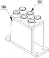
图2是AGV物料托盘示意图;Figure 2 is a schematic diagram of the AGV material tray;
图3是托盘导向定位机构示意图;Figure 3 is a schematic diagram of a tray guiding and positioning mechanism;
图4是托盘承接机构示意图;Figure 4 is a schematic diagram of a tray receiving mechanism;
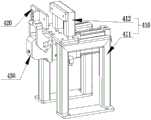
图5是机械定位机构示意图;5 is a schematic diagram of a mechanical positioning mechanism;
图6是AGV小车的示意图;Figure 6 is a schematic diagram of an AGV car;
图7是AGV物料托盘中AGV导向机构导向AGV小车的示意图;Figure 7 is a schematic diagram of the AGV guide mechanism guiding the AGV trolley in the AGV material tray;
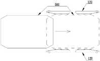
图8是托盘导向定位机构导向AGV小车及AGV物料托盘的示意图;Figure 8 is a schematic diagram of the tray guiding and positioning mechanism guiding the AGV trolley and the AGV material tray;
图9是托盘导向定位机构上机械限位机构的示意图。FIG. 9 is a schematic diagram of the mechanical limit mechanism on the tray guide positioning mechanism.
图中的标号分别代表:The symbols in the figure represent:
AGV物料托盘100;托盘框架110;托盘支撑板111;AGV导向机构120;AGV定位机构130;支撑板131;导向孔132;料仓支撑块140;托盘导向定位机构200;固定支架210;导轮组驱动装置220;导向滚轮组件230;滑轨组件240;机械限位机构250;限位件251;抵接件252;托盘承接机构300;承接支架310;万向球320;机械定位机构400;固定定位面机构410;支架411;固定件412;夹持件420;夹持气缸430;AGV小车500;导向销510;料仓600。
具体实施方式Detailed ways
为使本实用新型实施方式的目的、技术方案和优点更加清楚,下面将结合本实用新型实施方式中的附图,对本实用新型实施方式中的技术方案进行清楚、完整地描述,显然,所描述的实施方式是本实用新型一部分实施方式,而不是全部的实施方式。基于本实用新型中的实施方式,本领域普通技术人员在没有作出创造性劳动前提下所获得的所有其他实施方式,都属于本实用新型保护的范围。因此,以下对在附图中提供的本实用新型的实施方式的详细描述并非旨在限制要求保护的本实用新型的范围,而是仅仅表示本实用新型的选定实施方式。基于本实用新型中的实施方式,本领域普通技术人员在没有作出创造性劳动前提下所获得的所有其他实施方式,都属于本实用新型保护的范围。In order to make the purposes, technical solutions and advantages of the embodiments of the present invention more clear, the technical solutions in the embodiments of the present invention will be clearly and completely described below with reference to the accompanying drawings in the embodiments of the present invention. Obviously, the described The embodiments of the present invention are a part of the embodiments of the present invention, but not all of the embodiments. Based on the embodiments of the present invention, all other embodiments obtained by those of ordinary skill in the art without creative work fall within the protection scope of the present invention. Accordingly, the following detailed description of the embodiments of the invention provided in the accompanying drawings is not intended to limit the scope of the invention as claimed, but is merely representative of selected embodiments of the invention. Based on the embodiments of the present invention, all other embodiments obtained by those of ordinary skill in the art without creative work fall within the protection scope of the present invention.
在本实用新型的描述中,术语“第一”、“第二”仅用于描述目的,而不能理解为指示或暗示相对重要性或者隐含指明所指示的技术特征的数量。由此,限定有“第一”、“第二”的特征可以明示或者隐含地包括一个或者更多个该特征。在本实用新型的描述中,“多个”的含义是两个或两个以上,除非另有明确具体的限定。In the description of the present invention, the terms "first" and "second" are only used for the purpose of description, and cannot be understood as indicating or implying relative importance or implying the number of indicated technical features. Thus, a feature defined as "first" or "second" may expressly or implicitly include one or more of that feature. In the description of the present invention, "plurality" means two or more, unless otherwise expressly and specifically defined.
参照附图1,一种AGV物料托盘定位装置,包括AGV小车500、AGV物料托盘100、用于AGV物料托盘100左右定位的托盘导向定位机构200、用于支撑AGV物料托盘100的托盘承接机构300与用于AGV物料托盘100前后定位的机械定位机构400;Referring to FIG. 1, an AGV material tray positioning device includes an
参照附图1和2,上述AGV物料托盘100包括托盘框架110、AGV导向机构120、AGV定位机构130、料仓支撑块140与定位销150,托盘框架110的顶部两侧对称设置有多组料仓支撑块140,定位销150交替设置于两侧料仓支撑块140的顶部,托盘框架110内侧顶面中部固定有AGV定位机构130,AGV定位机构130由支撑板131及开设于支撑板131四角的导向孔132组成,托盘框架110的内部两侧壁上对称设置有AGV导向机构120,其中AGV导向机构120由固定框与安装于固定框内的滚轮组构成,托盘框架110的底部两侧设置有与托盘承接机构300进行抵接配合的托盘支撑板111;1 and 2, the above-mentioned
参照附图6,上述AGV小车500的顶部设置有与导向孔132相配合的导向销510;其中AGV小车500为承载平台具有升降功能的常规现有技术中的AGV小车;6, the top of the above-mentioned AGV
参照附图1、3和9,上述托盘导向定位机构200分为左右两组平行设置,托盘导向定位机构200包括固定支架210、导轮组驱动装置220、导向滚轮组件230、滑轨组件240与机械限位机构250,其中导向滚轮组件230由上下连接板及均匀设置于上下连接板之间的滚轮组成;导向滚轮组件230通过滑轨组件240滑动连接于固定支架210的顶部,导轮组驱动装置220安装于固定支架210的顶部,且其伸缩端与导向滚轮组件230相连接,机械限位机构250包括限位件251与抵接件252,限位件251固定于固定支架210侧部,抵接件252固定于导向滚轮组件230的底部;其中导轮组驱动装置220可选用伸缩气缸,也可采用其它直线驱动机构。Referring to Figures 1, 3 and 9, the above-mentioned tray guiding and
参照附图1和4,上述托盘承接机构300左右各两组设于两组托盘导向定位机构200之间,托盘承接机构300包括承接支架310与万向球320,万向球320均匀设置于承接支架310的顶部;AGV物料托盘100放置于托盘承接机构300顶部后可进行前后左右的滑动。Referring to Figures 1 and 4 , two groups of the above-mentioned
参照附图1和5,上述机械定位机构400设于托盘承接机构300的前端,其包括固定定位面机构410、夹持件420与夹紧气缸430,其中固定定位面机构410由支架411以及固定安装于支架411顶部的固定件412组成;固定定位面机构410上固定安装有夹紧气缸430,夹紧气缸430输出转轴上安装有夹持件420;其中夹紧气缸430为常规现有技术,其可带动夹持件420绕其输出转轴进行来回翻转,进而实现夹持动作,用于夹持托盘框架110的前端横杆,以实现AGV物料托盘100前后精定位。机械定位机构400初始时,夹持件420呈水平或水平向下倾斜的状态,夹持时夹紧气缸430带动夹持件420向上翻转。1 and 5, the above-mentioned
参照附图1,托盘支撑板111到托盘框架110支脚的距离小于托盘承接机构300的高度;当托盘支撑板111与托盘承接机构300相抵接时,托盘框架110支脚能够脱离地面。1 , the distance from the
参照附图3,滑轨组件240由线性滑轨与滑块组成,线性滑轨固定于固定支架210的顶部两侧,滑块分别固定于导向滚轮组件230的底部两侧,两侧滑块分别与两侧线性滑轨滑动连接。Referring to FIG. 3 , the
参照附图1与7,AGV小车500进入到AGV物料托盘100内后,AGV小车500与两侧AGV导向机构120的双边间隙小于10mm;AGV小车500进入AGV物料托盘100内后,使AGV小车500与AGV物料托盘100的中心线最终偏差缩小到±5mm以内,实现AGV小车500的左右位置调整。Referring to Figures 1 and 7, after the
参照附图1和2,两侧料仓支撑块140的顶部交替设置有定位销150;使用时,料仓600放置于AGV物料托盘100顶部,料仓600的底部开设有与定位销150相匹配的圆孔槽,以实现料仓600的定位及防止料仓600的滑落。Referring to Figures 1 and 2, the tops of the silo support blocks 140 on both sides are alternately provided with
参照附图9,两侧托盘导向定位机构200上的导轮组驱动装置220伸长至限位件251与抵接件252相抵接时,两侧导向滚轮组件230之间的最短间距等于AGV物料托盘100的宽度;即两侧导轮组驱动装置220伸长至限位件251与抵接件252相抵接时,AGV物料托盘100正好被推至正中间位置。Referring to FIG. 9 , when the guide roller
AGV物料托盘定位装置使用时,将托盘导向定位机构200安装在机器人需要抓取料仓的指定位置地面,分左右两组托盘导向定位机构200进行安装,托盘承接机构300左右各两组设于两组托盘导向定位机构200之间,机械定位机构400设于托盘承接机构300的前端。When the AGV material tray positioning device is used, the tray guiding and
工作原理:working principle:
AGV小车500根据设定好的导航行驶至AGV物料托盘100的正前方,此时AGV小车500中心线与AGV物料托盘100的中心线可能会有±20mm以内的偏差。当AGV小车500进入AGV物料托盘100时,依靠物料托盘下方的AGV导向机构120导轮组进行导正粗定位,使AGV小车500与AGV物料托盘100最终偏差缩小到±5mm以内(如附图7所示)。AGV小车500前进到位停止后,其承载平台上升,承载平台上的导向销510插入AGV物料托盘100上的导向孔132,并继续上升使AGV物料托盘100脱离地面。AGV小车500载着AGV物料托盘100行驶至机器人抓取工位(即需要精定位的工位)前方。此时AGV小车500中心线与精定位工位的中心线可能会有±20mm以内的偏差。托盘导向定位机构200的导向滚轮组件230先退回,然后AGV小车500缓慢行驶进入精定位工位,此过程中,导向滚轮组件230与AGV物料托盘100侧壁相抵接对AGV小车500进行导正(如附图8所示)。AGV小车继续前进,直至AGV物料托盘100抵住机械定位机构400的固定件412。AGV小车500承载平台下降,将AGV物料托盘100放在承接平台300上,AGV物料托盘100的支脚不接触地面。AGV小车500行驶离开,托盘导向定位机构200两侧的导向轮组230推出至自身机械限位,把AGV物料托盘100推至正中间位置,此时AGV物料托盘100中心线与精定位工位中心线偏差可缩小到±2mm以内。进一步的机械定位机构400的夹持件420夹住AGV物料托盘100的前端横杆,实现托盘前后精定位。至此AGV物料托盘100的前后左右已经被完全固定住,从而实现了AGV物料托盘100的精准定位,满足机器人精准抓取料仓600的功能。The
以上所述仅为本实用新型的优选实施方式而已,并不用于限制本实用新型,对于本领域的技术人员来说,本实用新型可以有各种更改和变化。凡在本实用新型的精神和原则之内,所作的任何修改、等同替换、改进等,均应包括在本实用新型的保护范围之内。The above descriptions are only preferred embodiments of the present invention, and are not intended to limit the present invention. For those skilled in the art, the present invention may have various modifications and changes. Any modification, equivalent replacement, improvement, etc. made within the spirit and principle of the present invention shall be included in the protection scope of the present invention.
Claims (6)
Translated fromChinesePriority Applications (1)
| Application Number | Priority Date | Filing Date | Title |
|---|---|---|---|
| CN201922318676.6UCN211495528U (en) | 2019-12-20 | 2019-12-20 | AGV material tray positioner |
Applications Claiming Priority (1)
| Application Number | Priority Date | Filing Date | Title |
|---|---|---|---|
| CN201922318676.6UCN211495528U (en) | 2019-12-20 | 2019-12-20 | AGV material tray positioner |
Publications (1)
| Publication Number | Publication Date |
|---|---|
| CN211495528Utrue CN211495528U (en) | 2020-09-15 |
Family
ID=72417974
Family Applications (1)
| Application Number | Title | Priority Date | Filing Date |
|---|---|---|---|
| CN201922318676.6UActiveCN211495528U (en) | 2019-12-20 | 2019-12-20 | AGV material tray positioner |
Country Status (1)
| Country | Link |
|---|---|
| CN (1) | CN211495528U (en) |
Cited By (3)
| Publication number | Priority date | Publication date | Assignee | Title |
|---|---|---|---|---|
| CN111038944A (en)* | 2019-12-20 | 2020-04-21 | 百特(福建)智能装备科技有限公司 | AGV material tray positioner |
| CN113955372A (en)* | 2021-11-22 | 2022-01-21 | 株洲时代新材料科技股份有限公司 | Air spring transferring and positioning method and transferring device |
| CN114537940A (en)* | 2021-10-28 | 2022-05-27 | 北京迈格威科技有限公司 | Shuttle vehicle for warehousing system, warehousing system and control method of shuttle vehicle |
- 2019
- 2019-12-20CNCN201922318676.6Upatent/CN211495528U/enactiveActive
Cited By (3)
| Publication number | Priority date | Publication date | Assignee | Title |
|---|---|---|---|---|
| CN111038944A (en)* | 2019-12-20 | 2020-04-21 | 百特(福建)智能装备科技有限公司 | AGV material tray positioner |
| CN114537940A (en)* | 2021-10-28 | 2022-05-27 | 北京迈格威科技有限公司 | Shuttle vehicle for warehousing system, warehousing system and control method of shuttle vehicle |
| CN113955372A (en)* | 2021-11-22 | 2022-01-21 | 株洲时代新材料科技股份有限公司 | Air spring transferring and positioning method and transferring device |
Similar Documents
| Publication | Publication Date | Title |
|---|---|---|
| CN111038944A (en) | AGV material tray positioner | |
| CN211495528U (en) | AGV material tray positioner | |
| CN105346959B (en) | A kind of random switching device of vehicle body shaping jig | |
| CN106628784B (en) | A conveyor frame applied to a logistics palletizer | |
| CN109421576B (en) | Carrying trolley | |
| CN110641980A (en) | Microscope carrier convenient to lifting carrier and assembly line that contains microscope carrier | |
| CN204624556U (en) | Extraordinary AGV | |
| CN111302007B (en) | A multi-stage transfer device for production line workpieces | |
| CN204624479U (en) | Loading and unloading mechanism | |
| CN218255128U (en) | An intelligent logistics handling robot | |
| CN109808793B (en) | Carrying trolley and using method thereof | |
| CN219546627U (en) | An automated loading and unloading system | |
| CN203237995U (en) | Automatic forklift | |
| CN210063202U (en) | Accurate positioning butt joint device of robot trolley | |
| CN206624390U (en) | A kind of sheet material handling robot system | |
| CN212221674U (en) | A hospital logistics handling and storage equipment | |
| CN203922609U (en) | PCB automatic lifter | |
| CN212173698U (en) | Multistage transfer device of production line work piece | |
| CN116639494A (en) | Humanoid clamp type mobile operation robot | |
| CN211594166U (en) | Microscope carrier convenient to lifting carrier and assembly line that contains microscope carrier | |
| CN210941115U (en) | Loading attachment and glass cnc engraving and milling equipment | |
| CN115973309B (en) | Four-way transport vehicle | |
| CN219279409U (en) | Jacking structure for four-way transport vehicle | |
| CN221820916U (en) | A shelf positioning mechanism for an AGV intelligent handling robot | |
| CN218491386U (en) | Automatic stacking mechanism for trays and three-dimensional storage system |
Legal Events
| Date | Code | Title | Description |
|---|---|---|---|
| GR01 | Patent grant | ||
| GR01 | Patent grant | ||
| TR01 | Transfer of patent right | Effective date of registration:20210702 Address after:644007 No. 150 Minjiang West Road, Yibin, Sichuan Patentee after:WULIANGYE GROUP Co.,Ltd. Address before:350000 Building 1, 6 Xincheng Avenue, Xiaojiao Industrial Park, Meilie District, Sanming City, Fujian Province Patentee before:BAITE (FUJIAN) INTELLIGENT EQUIPMENT TECHNOLOGY Co.,Ltd. | |
| TR01 | Transfer of patent right |