CN211483984U - Cooking utensil - Google Patents
Cooking utensilDownload PDFInfo
- Publication number
- CN211483984U CN211483984UCN201921292493.5UCN201921292493UCN211483984UCN 211483984 UCN211483984 UCN 211483984UCN 201921292493 UCN201921292493 UCN 201921292493UCN 211483984 UCN211483984 UCN 211483984U
- Authority
- CN
- China
- Prior art keywords
- steam
- sealing member
- cooking
- cover
- steam passage
- Prior art date
- Legal status (The legal status is an assumption and is not a legal conclusion. Google has not performed a legal analysis and makes no representation as to the accuracy of the status listed.)
- Active
Links
- 238000010411cookingMethods0.000titleclaimsabstractdescription92
- 238000007789sealingMethods0.000claimsabstractdescription128
- 238000009413insulationMethods0.000claimsabstractdescription30
- 238000004321preservationMethods0.000claimsdescription13
- XLYOFNOQVPJJNP-UHFFFAOYSA-NwaterSubstancesOXLYOFNOQVPJJNP-UHFFFAOYSA-N0.000claimsdescription7
- 238000005406washingMethods0.000abstract1
- 230000000694effectsEffects0.000description14
- 238000000034methodMethods0.000description9
- 241000209094OryzaSpecies0.000description7
- 235000007164Oryza sativaNutrition0.000description7
- 235000009566riceNutrition0.000description7
- 238000004140cleaningMethods0.000description4
- 235000013305foodNutrition0.000description3
- 238000012423maintenanceMethods0.000description3
- 230000002159abnormal effectEffects0.000description2
- 230000009286beneficial effectEffects0.000description2
- 238000010276constructionMethods0.000description2
- 238000005260corrosionMethods0.000description2
- 230000007797corrosionEffects0.000description2
- 238000004519manufacturing processMethods0.000description2
- 238000012986modificationMethods0.000description2
- 230000004048modificationEffects0.000description2
- 230000003749cleanlinessEffects0.000description1
- 238000010438heat treatmentMethods0.000description1
- 239000004615ingredientSubstances0.000description1
- 230000003020moisturizing effectEffects0.000description1
- 235000021395porridgeNutrition0.000description1
- 238000011084recoveryMethods0.000description1
- 238000000926separation methodMethods0.000description1
- 235000014347soupsNutrition0.000description1
Images


Classifications
- A—HUMAN NECESSITIES
- A47—FURNITURE; DOMESTIC ARTICLES OR APPLIANCES; COFFEE MILLS; SPICE MILLS; SUCTION CLEANERS IN GENERAL
- A47J—KITCHEN EQUIPMENT; COFFEE MILLS; SPICE MILLS; APPARATUS FOR MAKING BEVERAGES
- A47J27/00—Cooking-vessels
- A47J27/002—Construction of cooking-vessels; Methods or processes of manufacturing specially adapted for cooking-vessels
- A—HUMAN NECESSITIES
- A47—FURNITURE; DOMESTIC ARTICLES OR APPLIANCES; COFFEE MILLS; SPICE MILLS; SUCTION CLEANERS IN GENERAL
- A47J—KITCHEN EQUIPMENT; COFFEE MILLS; SPICE MILLS; APPARATUS FOR MAKING BEVERAGES
- A47J27/00—Cooking-vessels
- A47J27/04—Cooking-vessels for cooking food in steam; Devices for extracting fruit juice by means of steam ; Vacuum cooking vessels
- A—HUMAN NECESSITIES
- A47—FURNITURE; DOMESTIC ARTICLES OR APPLIANCES; COFFEE MILLS; SPICE MILLS; SUCTION CLEANERS IN GENERAL
- A47J—KITCHEN EQUIPMENT; COFFEE MILLS; SPICE MILLS; APPARATUS FOR MAKING BEVERAGES
- A47J27/00—Cooking-vessels
- A47J27/08—Pressure-cookers; Lids or locking devices specially adapted therefor
- A—HUMAN NECESSITIES
- A47—FURNITURE; DOMESTIC ARTICLES OR APPLIANCES; COFFEE MILLS; SPICE MILLS; SUCTION CLEANERS IN GENERAL
- A47J—KITCHEN EQUIPMENT; COFFEE MILLS; SPICE MILLS; APPARATUS FOR MAKING BEVERAGES
- A47J36/00—Parts, details or accessories of cooking-vessels
- A—HUMAN NECESSITIES
- A47—FURNITURE; DOMESTIC ARTICLES OR APPLIANCES; COFFEE MILLS; SPICE MILLS; SUCTION CLEANERS IN GENERAL
- A47J—KITCHEN EQUIPMENT; COFFEE MILLS; SPICE MILLS; APPARATUS FOR MAKING BEVERAGES
- A47J36/00—Parts, details or accessories of cooking-vessels
- A47J36/06—Lids or covers for cooking-vessels
Landscapes
- Engineering & Computer Science (AREA)
- Food Science & Technology (AREA)
- Manufacturing & Machinery (AREA)
- Cookers (AREA)
- Resistance Heating (AREA)
Abstract
Description
Translated fromChinese技术领域technical field
本实用新型总地涉及烹饪器具。The present invention generally relates to cooking appliances.
背景技术Background technique
烹饪器具为了达到蒸汽回收或者蒸汽保湿目的,通常会在煲体中设置蒸汽杯,用于产生蒸汽。为了有效减小烹饪器具的体积,申请人设计了一种将蒸汽杯设置在盖体中的新型烹饪器具。然而,在工作中,蒸汽杯中的蒸汽需要通过盖体内的蒸汽通道输送至内锅,其中涉及到蒸汽通道与盖体内部元器件的密封问题。In order to achieve the purpose of steam recovery or steam moisturizing, a cooking appliance usually has a steam cup in the pot body for generating steam. In order to effectively reduce the volume of the cooking appliance, the applicant has designed a novel cooking appliance in which the steam cup is arranged in the cover. However, during operation, the steam in the steam cup needs to be transported to the inner pot through the steam channel in the cover body, which involves the sealing problem between the steam channel and the internal components of the cover body.
因此,需要一种烹饪器具,以至少部分地解决上述问题。Therefore, there is a need for a cooking appliance that at least partially addresses the above-mentioned problems.
实用新型内容Utility model content
在实用新型内容部分中引入了一系列简化形式的概念,这将在具体实施方式部分中进一步详细说明。本实用新型的实用新型内容部分并不意味着要试图限定出所要求保护的技术方案的关键特征和必要技术特征,更不意味着试图确定所要求保护的技术方案的保护范围。A series of concepts in simplified form have been introduced in the Summary of the Invention, which are described in further detail in the Detailed Description. The utility model content part of the present utility model is not intended to attempt to limit the key features and necessary technical features of the claimed technical solution, nor does it mean to attempt to determine the protection scope of the claimed technical solution.
为至少部分地解决上述问题,本实用新型提供一种烹饪器具,所述烹饪器具包括:In order to at least partially solve the above problems, the present invention provides a cooking utensil, the cooking utensil includes:
煲体,所述煲体中设置有内锅;a pot body, wherein the pot body is provided with an inner pot;
盖体,所述盖体可开合地设置于所述煲体上,所述盖体包括内衬和可拆盖,当所述盖体盖合所述煲体时,所述可拆盖和所述内锅之间构成烹饪空间,所述内衬上设置有保温板,所述盖体中设置有与所述烹饪空间连通的蒸汽通道;A cover body, the cover body can be opened and closed on the pot body, the cover body includes an inner lining and a removable cover, when the cover body covers the pot body, the removable cover and the removable cover A cooking space is formed between the inner pots, a heat preservation plate is arranged on the inner lining, and a steam passage communicated with the cooking space is arranged in the cover body;
蒸汽发生装置,所述蒸汽发生装置用于产生辅助烹饪的蒸汽,所述蒸汽发生装置设置在所述盖体中,所述蒸汽通道包括第一蒸汽通道,所述蒸汽发生装置能够通过所述第一蒸汽通道与所述烹饪空间连通,以将蒸汽导入所述烹饪空间;以及A steam generating device, the steam generating device is used to generate steam for auxiliary cooking, the steam generating device is arranged in the cover body, the steam channel includes a first steam channel, and the steam generating device can pass through the first steam channel. A steam passage communicates with the cooking space for introducing steam into the cooking space; and
密封构件,所述密封构件包括第一密封件,所述第一密封件设置在所述第一蒸汽通道和所述可拆盖之间且连接至所述保温板,以在所述第一蒸汽通道和所述可拆盖之间形成密封。a sealing member including a first seal disposed between the first steam passage and the removable cover and connected to the thermal insulation panel for use in the first steam A seal is formed between the channel and the removable cover.
根据本实用新型的烹饪器具,通过在第一蒸汽通道与可拆盖之间设置第一密封件,实现了对第一蒸汽通道和可拆盖连接处的密封,可以防止烹饪过程中蒸汽从第一蒸汽通道和可拆盖之间溢出,从而可以保护盖体内部的电子元器件的正常工作,同时更好地向烹饪空间中输送蒸汽以提高烹饪效果。另外通过将第一密封件安装在保温板上,可以保证可拆盖的结构简洁,从而方便清洗。According to the cooking utensil of the present invention, by arranging the first seal between the first steam channel and the removable cover, the sealing of the connection between the first steam channel and the removable cover is realized, which can prevent the steam from passing through the first steam channel during the cooking process. There is an overflow between the steam channel and the detachable cover, so that the normal operation of the electronic components inside the cover body can be protected, and the steam can be better transported into the cooking space to improve the cooking effect. In addition, by installing the first sealing member on the thermal insulation board, the structure of the removable cover can be kept simple, thereby facilitating cleaning.
优选地,所述第一密封件的一端密封抵靠至所述第一蒸汽通道,另一端密封抵靠至所述可拆盖。该方案通过将第一密封件安装在保温板上,并使其两端分别抵靠至第一蒸汽通道和可拆盖,可以便于第一密封件的装配,并且可以保证密封效果。Preferably, one end of the first seal is sealed against the first steam passage and the other end is sealed against the removable cover. In this solution, by installing the first sealing member on the thermal insulation board and making its two ends abut against the first steam passage and the detachable cover, the assembly of the first sealing member can be facilitated and the sealing effect can be ensured.
优选地,所述第一蒸汽通道的底端设置有阶梯部,所述第一密封件的一端套设在所述阶梯部处。该方案可以进一步保证第一密封件和第一蒸汽通道的连接处的密封效果,并且该方案还可以便于对第一密封件进行装配定位。Preferably, the bottom end of the first steam passage is provided with a stepped portion, and one end of the first sealing member is sleeved at the stepped portion. This solution can further ensure the sealing effect of the connection between the first sealing member and the first steam passage, and this solution can also facilitate the assembly and positioning of the first sealing member.
优选地,所述第一密封件上设置有用于卡设在所述保温板上的卡槽结构。该方案便于第一密封件的装配。Preferably, the first sealing member is provided with a slot structure for being clamped on the thermal insulation board. This solution facilitates the assembly of the first seal.
优选地,所述第一密封件与所述第一蒸汽通道在其径向方向上过盈配合。该方案可以便于第一密封件的装配并且可以保证密封效果。Preferably, the first seal is an interference fit with the first steam passage in its radial direction. This solution can facilitate the assembly of the first seal and can ensure the sealing effect.
优选地,所述保温板的与所述第一蒸汽通道接合的端部沿轴向方向设置在所述第一蒸汽通道的最底端之上,且所述保温板的所述端部和所述第一蒸汽通道的最底端之间的轴向尺寸B1满足:0<B1<30mm。该方案允许套设在第一蒸汽通道上的第一密封件沿轴向方向具有一定的厚度,以提高强度、密封性及与保温板的连接的可靠性。Preferably, the end portion of the heat preservation plate that is engaged with the first steam passage is disposed above the bottommost end of the first steam passage in the axial direction, and the end portion of the heat preservation plate and the The axial dimension B1 between the bottommost ends of the first steam passages satisfies: 0<B1<30mm. This solution allows the first sealing member sleeved on the first steam passage to have a certain thickness along the axial direction, so as to improve the strength, the sealing performance and the reliability of the connection with the thermal insulation board.
优选地,所述烹饪器具还包括蒸汽阀,所述蒸汽通道还包括第二蒸汽通道,所述第二蒸汽通道设置在所述蒸汽阀中,所述烹饪空间能够通过所述第二蒸汽通道与外界连通。该方案可以使烹饪空间相对于外界保持微压,以利用压力改善食物的口感,从而提高烹饪效果,同时起到防溢的作用。Preferably, the cooking appliance further includes a steam valve, the steam channel further includes a second steam channel, the second steam channel is arranged in the steam valve, and the cooking space can communicate with the cooking space through the second steam channel. External connection. This solution can keep the cooking space at a slight pressure relative to the outside, so as to use the pressure to improve the taste of the food, thereby improving the cooking effect, and at the same time, it can prevent overflow.
优选地,所述密封构件包括第二密封件,所述第二密封件设置在所述第二蒸汽通道和所述可拆盖之间,以在所述第二蒸汽通道和所述可拆盖之间形成密封。该方案通过在第二蒸汽通道与可拆盖之间设置第二密封件,实现了对第二蒸汽通道和可拆盖连接处的密封,可以防止烹饪过程中蒸汽从第二蒸汽通道和可拆盖之间溢出,从而可以保护盖体内部的电子元器件的正常工作,同时更好地向烹饪空间中输送蒸汽以提高烹饪效果。Preferably, the sealing member includes a second sealing member disposed between the second steam passage and the removable cover so as to provide a space between the second steam passage and the removable cover A seal is formed between. In this solution, by arranging a second sealing member between the second steam channel and the detachable cover, the sealing of the connection between the second steam channel and the detachable cover is realized, which can prevent the steam from passing from the second steam channel and the detachable cover during the cooking process. There is overflow between the lids, so that the electronic components inside the lid can be protected from normal work, and at the same time, the steam can be better delivered to the cooking space to improve the cooking effect.
优选地,所述第二密封件连接在所述保温板、所述第二蒸汽通道和所述可拆盖中的一个上。该方案可以便于第二密封件的装配,并保证密封效果。Preferably, the second seal is connected to one of the thermal insulation board, the second steam passage and the removable cover. This solution can facilitate the assembly of the second seal and ensure the sealing effect.
优选地,所述蒸汽发生装置包括:Preferably, the steam generating device includes:
蒸汽发生腔,所述蒸汽发生腔用于容纳待被加热以生成蒸汽的水,所述蒸汽发生腔能够通过所述第一蒸汽通道与所述烹饪空间连通;和a steam generating chamber for accommodating water to be heated to generate steam, the steam generating chamber being able to communicate with the cooking space through the first steam passage; and
蒸汽盖板,所述蒸汽盖板连接至所述盖体,并且能够相对于所述蒸汽发生腔开合以打开或盖合所述蒸汽发生腔。The steam cover plate is connected to the cover body and can be opened and closed relative to the steam generation chamber to open or cover the steam generation chamber.
该方案可以通过将蒸汽盖板连接至盖体,一方面可以在烹饪时使蒸汽盖板盖合蒸汽发生腔,从而保证安全性,另一方面可以通过将蒸汽盖板打开而向蒸汽发生腔中加水。In this solution, by connecting the steam cover plate to the cover body, on the one hand, the steam cover plate can cover the steam generating chamber during cooking, so as to ensure safety, and on the other hand, the steam generating chamber can be opened by opening the steam cover plate. add water.
附图说明Description of drawings
本实用新型实施方式的下列附图在此作为本实用新型的一部分用于理解本实用新型。附图中示出了本实用新型的实施方式及其描述,用来解释本实用新型的原理。在附图中,The following drawings of embodiments of the present invention are incorporated herein as a part of the present invention for understanding of the present invention. The accompanying drawings illustrate the embodiments of the present invention and their description, which are used to explain the principles of the present invention. In the attached drawings,
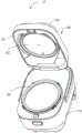
图1为根据本实用新型的烹饪器具的立体视图;1 is a perspective view of a cooking appliance according to the present invention;
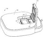
图2为图1所示的烹饪器具的盖体的立体视图;FIG. 2 is a perspective view of the cover of the cooking appliance shown in FIG. 1;
图3为根据本实用新型的第一实施方式的烹饪器具的盖体的一部分的剖视图;3 is a cross-sectional view of a portion of the cover of the cooking appliance according to the first embodiment of the present invention;
图4为图3所示的盖体的分解示意图;FIG. 4 is an exploded schematic view of the cover shown in FIG. 3;
图5为根据本实用新型的第二实施方式的烹饪器具的盖体的一部分的剖视图;5 is a cross-sectional view of a portion of a cover of a cooking appliance according to a second embodiment of the present invention;
图6为图5所示的盖体的分解示意图;6 is an exploded schematic view of the cover shown in FIG. 5;
图7为根据本实用新型的第三实施方式的烹饪器具的盖体的一部分的剖视图;7 is a cross-sectional view of a portion of a cover of a cooking appliance according to a third embodiment of the present invention;
图8为图7所示的盖体的分解示意图。FIG. 8 is an exploded schematic view of the cover shown in FIG. 7 .
附图标记说明:Description of reference numbers:
烹饪器具10 盖体100/200/300
可拆盖101 内衬102
面盖103 保温板104
蒸汽发生腔111 蒸汽盖板112
第一蒸汽通道121 第二蒸汽通道122
第一密封件131/231/331 第二密封件132/232/332
煲体110 内锅201
蒸汽发生装置150 蒸汽阀120
卡槽结构134/334 阶梯部123
套筒结构233 配合部234
限位钩234a 轴向方向ADLimiting
径向方向RDRadial direction RD
具体实施方式Detailed ways
在下文的描述中,给出了大量具体的细节以便提供对本实用新型更为彻底的理解。然而,对于本领域技术人员来说显而易见的是,本实用新型实施方式可以无需一个或多个这些细节而得以实施。在其他的例子中,为了避免与本实用新型实施方式发生混淆,对于本领域公知的一些技术特征未进行描述。In the following description, numerous specific details are set forth in order to provide a more thorough understanding of the present invention. It will be apparent, however, to one skilled in the art that embodiments of the invention may be practiced without one or more of these details. In other instances, in order to avoid confusion with the embodiments of the present invention, some technical features known in the art are not described.
为了彻底了解本实用新型实施方式,将在下列的描述中提出详细的结构。显然,本实用新型实施方式的施行并不限定于本领域的技术人员所熟习的特殊细节。For a thorough understanding of the embodiments of the present invention, detailed structures will be presented in the following description. Obviously, the implementation of the embodiments of the present invention is not limited to the specific details familiar to those skilled in the art.
本实用新型提供了一种烹饪器具10。根据本实用新型的烹饪器具10可以为电饭煲、电压力锅或其他的烹饪器具,并且根据本实用新型的烹饪器具10除具有煮米饭的功能以外,还可以具有煮粥、煲汤、炒菜等各种功能。下面结合附图对本实用新型的优选实施方式进行说明。The utility model provides a
第一实施方式first embodiment
如图1所示,根据本实用新型的烹饪器具10包括煲体110和盖体100。煲体110可以大致构造为圆角长方体的形状,其内部设置有内锅201。盖体100以可开合的方式设置在煲体110上。因此,盖体100通常具有与煲体110形状相适应的形状,从而能够方便地盖合煲体110。盖体100包括面盖103、内衬102和可拆盖101。内衬102设置在面盖103和可拆盖101之间,内衬102上设置有保温板104,用于使盖体100在烹饪过程中保持适当的温度以避免冷凝水的产生及滴落,从而提高烹饪效果。可拆盖101可拆卸地连接在内衬102下方,以便于拆卸清洗及维修。As shown in FIG. 1 , the
当盖体100相对于煲体110打开时,煲体110中的内锅201的开口露出,用户可以向内锅201中添加食材或从内锅201中取出烹饪好的食物。当盖体100盖合在煲体110上时,其覆盖在内锅201之上,并且可拆盖101和内锅201之间构成烹饪空间。When the
根据本实用新型的烹饪器具10还设置有蒸汽发生装置150。如图2所示,蒸汽发生装置150设置在盖体100中,其用于产生辅助烹饪的蒸汽。相应地,在盖体100中设置有第一蒸汽通道121。在盖体100盖合煲体110的状态下,蒸汽发生装置150能够通过第一蒸汽通道121与烹饪空间连通,以便于将蒸汽导入烹饪空间内,辅助烹饪。以电饭煲为例,辅助烹饪的具体操作可以是,在煮饭过程中,将蒸汽发生装置150产生的蒸汽导入烹饪空间内,从米饭的上方进行加热,使米饭能够均匀受热,并且提高加热效率;或者还可以是在煮饭完成之后,将蒸汽发生装置150产生的蒸汽导入烹饪空间内,对米饭进行保温保鲜,使其保持良好的口感。The
优选地,根据本实用新型的蒸汽发生装置150包括蒸汽发生腔111和蒸汽盖板112。蒸汽发生腔111用于容纳待被加热以生成蒸汽的水。蒸汽发生腔111可以构造为凹陷的容纳部及其内部设置的单独水容器的形式,或者构造为与盖体100一体成型的凹陷部等形式。蒸汽发生腔111能够通过第一蒸汽通道121与烹饪空间连通,以便于在烹饪过程中将其中产生的蒸汽导入到烹饪空间内。蒸汽盖板112连接至盖体100并且能够相对于蒸汽发生腔111开合。图2所示的蒸汽盖板112处于打开状态,以便于用户观察蒸汽发生腔111内的水位以及清洁程度等。Preferably, the
为了使蒸汽导入烹饪空间的过程更加高效和安全,需要在第一蒸汽通道121与盖体100之间设置密封构件。具体地,在本实用新型的实施方式中,第一蒸汽通道121和可拆盖之间设置有第一密封件131,使蒸汽在经由第一蒸汽通道121流至烹饪空间的流通过程能够保持良好的密封性,同时保护盖体100内部的电子元器件免受蒸汽影响,防止其发生非正常导通或腐蚀。In order to make the process of introducing steam into the cooking space more efficient and safe, a sealing member needs to be provided between the
优选地,如图2和图3所示,烹饪器具的盖体100上还设置有蒸汽阀120。蒸汽阀120内设置有贯通的第二蒸汽通道122,用于在烹饪期间向外界输送内锅中的蒸汽。例如,当盖体100盖合煲体110时,烹饪空间可以通过蒸汽阀120的第二蒸汽通道122与外界大气连通。其中,第二蒸汽通道122可以构造为迷宫状,防止蒸汽经由蒸汽阀120轻易地大量泄出。因此,蒸汽阀120能够使烹饪空间相对于外界保持微压,以利用压力改善食物的口感,从而提高烹饪效果,同时起到防溢的作用。Preferably, as shown in FIG. 2 and FIG. 3 , a
优选地,与第一密封件131相似,在本实用新型的实施方式中,第二蒸汽通道122与可拆盖101之间设置有第二密封件132,使蒸汽在经由第二蒸汽通道122流向外界的流通过程能够保持良好的密封性,同时保护盖体100内部的电子元器件免受蒸汽影响,防止发生非正常导通或腐蚀。Preferably, similar to the
此外,第一密封件131与第二密封件132可以具有大致相同的结构,以降低生产成本与装配难度。然而,在未示出的实施方式中,第一密封件131与第二密封件132也可以具有不同的结构。In addition, the
优选地,如图3和图4所示,在本实施方式中,第一密封件131和第二密封件132均连接至保温板104,且上端分别抵靠至第一蒸汽通道121和第二蒸汽通道122,下端抵靠至可拆盖101。具体地,如图3所示,第一密封件131和第二密封件132构造为具有卡槽结构134的环形形状,保温板104上设置有通孔,且保温板104的围成通孔的端部插在卡槽结构134中。可以理解,保温板104在轴向方向AD上具有一厚度尺寸。相应地,第一密封件131和第二密封件132的卡槽结构134具有与保温板104的厚度尺寸配合的槽部尺寸,从而使第一密封件131和第二密封件132以卡设的方式与保温板104紧密地连接,实现第一密封件131和第二密封件132的固定。需要说明的是,本文中所提及的诸如“上”、“下”、“纵向”、“轴向”等方向术语均是基于放置在水平面上的烹饪器具10而言的。Preferably, as shown in FIG. 3 and FIG. 4 , in this embodiment, the
优选地,第一密封件131和第二密封件132密封抵靠至第一蒸汽通道121和第二蒸汽通道122。具体地,通过第一密封件131和第二密封件132的卡槽结构134的固定,使卡槽结构134的内表面(也就是槽部)与保温板104配合,而外表面与第一蒸汽通道121和第二蒸汽通道122配合。在图示实施方式中,第一蒸汽通道121和第二蒸汽通道122的最底端设置有沿径向方向从其外壁向内凹进的阶梯部123,以便于将第一密封件131和第二密封件132进一步地固定在阶梯部123中。可以理解,具有环形形状的第一密封件131和第二密封件132可以套设在第一蒸汽通道121与第二蒸汽通道122的阶梯部123处,以实现对蒸汽通道的完全密封。此外,阶梯部123的设置使得蒸汽通道与密封构件在轴向方向AD与径向方向RD上均实现接触及紧密配合,从而提高密封效果,且便于装配时的导向及定位。然而,在未示出的实施方式中,第一蒸汽通道121和第二蒸汽通道122也可以不设置阶梯部123,而通过密封构件直接地套设或者其他方式来密封蒸汽通道。Preferably, the
并且,第一密封件131和第二密封件132分别与第一蒸汽通道121和第二蒸汽通道122在其径向方向上过盈配合,从而进一步提高密封效果与装配的可靠性。具体地,过盈量的范围为0至1mm,优选地为0.1至0.5mm。In addition, the
如图3所示,第一密封件131和第二密封件132沿轴向方向AD的与卡槽结构134相对的自由端具有大致V形结构,该V形结构密封抵靠至可拆盖101,从而实现蒸汽通道与可拆盖101之间的完全密封,以保证盖体100内部的电子元器件正常工作。同时,第一密封件131和第二密封件132与可拆盖101之间不存在连接关系,从而保持可拆盖101的结构简洁,以便于拆卸清洗及维修。As shown in FIG. 3 , the free ends of the
优选地,在图示实施方式中,第一蒸汽通道121和第二蒸汽通道122结构沿轴向方向AD延伸并突出保温板104。可以理解,这允许设置在蒸汽通道的阶梯部123中的第一密封件131和第二密封件132的卡槽结构134具有沿轴向方向AD的相应的厚度尺寸,以提高强度、密封性及与保温板104的连接的可靠性。具体地,如图3所示,保温板104的与蒸汽通道接合的端部沿轴向方向AD设置在蒸汽通道的最底端之上,并且保温板104的端部和蒸汽通道的最底端之间的轴向尺寸B1限定为:0<B1<30mm。示例性地,轴向尺寸B1可以为10mm或20mm。Preferably, in the illustrated embodiment, the structures of the
第二实施方式Second Embodiment
以下参照图5和图6对本实用新型的第二个优选实施方式进行说明。图5和图6是按照本实用新型的第二个优选实施方式的盖体的示意图。如图5和图6所示,除了第一密封件和第二密封件与盖体装配的位置,以及第一蒸汽通道和第二蒸汽通道的最底端的结构之外,盖体200具有与盖体100大致相同的构造。由此,为简洁起见,此处不再详细描述与第一实施方式中的那些结构具有大致相同功能的结构。The second preferred embodiment of the present invention will be described below with reference to FIG. 5 and FIG. 6 . 5 and 6 are schematic views of the cover body according to the second preferred embodiment of the present invention. As shown in FIG. 5 and FIG. 6 , except for the positions where the first sealing member and the second sealing member are assembled with the cover body, and the structure of the bottommost end of the first steam passage and the second steam passage, the
优选地,如图5和图6所示,在第二实施方式中,第一密封件231和第二密封件232连接至蒸汽通道。具体地,如图5所示,第一密封件231和第二密封件232构造为具有套筒结构233的环形形状。第一密封件231和第二密封件232穿过保温板104,通过套筒结构233套设在第一蒸汽通道121和第二蒸汽通道122上,从而实现固定。因此,被固定的第一密封件231和第二密封件232的固定端实现蒸汽通道的密封,自由端则实现可拆盖的密封。Preferably, as shown in FIGS. 5 and 6 , in the second embodiment, the
优选地,第一蒸汽通道121和第二蒸汽通道122设置有供套筒结构233套设其上的配合部234,配合部构造为阶梯形状。具体地,第一蒸汽通道121和第二蒸汽通道122的配合部234沿径向方向从其外壁向内凹进,以便于将第一密封件231和第二密封件232紧密地固定在阶梯部中。可以理解,凹进的配合部234使得蒸汽通道与密封构件在轴向方向与径向方向上均实现接触及紧密配合,从而提高密封效果,且便于装配时的导向及定位。在图示实施方式中,第一蒸汽通道121和第二蒸汽通道122的配合部234的底端沿其周向方向设置有限位钩234a。限位钩234a构造为配合部234底端的凸缘,沿径向方向从其内壁向外突出。在装配时,限位钩234a支撑第一密封件231和第二密封件232的套筒结构233,并防止套筒结构233在配合部234中相对于蒸汽通道移动甚至脱落,从而实现第一密封件231和第二密封件232的进一步固定及限位。然而,第一蒸汽通道121和第二蒸汽通道122的配合部234的结构形式不限于该实施方式。Preferably, the
并且,第一密封件231和第二密封件232分别与第一蒸汽通道121和第二蒸汽通道122在其径向方向上过盈配合,从而进一步提高密封效果与装配的可靠性。具体地,过盈量的范围为0至1mm,优选地为0.1至0.5mm。In addition, the
如图5所示,第一密封件231和第二密封件232沿轴向方向的自由端具有大致V形结构,该V形结构密封抵靠至可拆盖101,从而实现蒸汽通道与可拆盖101之间的完全密封,以保证盖体内部的电子元器件正常工作。同时,第一密封件231和第二密封件232与可拆盖101之间不存在连接关系,从而保持可拆盖101的结构简洁,以便于拆卸清洗及维修。As shown in FIG. 5 , the free ends of the
优选地,在图示实施方式中,保温板104设置有供密封构件延伸穿过的通孔,蒸汽通道的配合部234沿径向方向凹入并避开保温板104的通孔的端部。可以理解,这允许保温板104与第一蒸汽通道121和第二蒸汽通道122之间存在间隙,有利于第一密封件231和第二密封件232的套筒结构的套入及固定操作,以降低装配难度。同时,设置在蒸汽通道的配合部234中的密封构件的套筒结构233可以具有沿径向方向的相应的厚度尺寸,以提高强度及与蒸汽通道的连接的可靠性。具体地,如图5所示,保温板104的通孔在径向方向上与蒸汽通道间隔开,保温板104的围成通孔的端部和配合部234的径向最外端之间的径向尺寸B2限定为:0<B2<30mm。示例性地,径向尺寸B2可以为10mm或20mm。Preferably, in the illustrated embodiment, the
第三实施方式Third Embodiment
以下参照图7和图8对本实用新型的第三个优选实施方式进行说明。图7和图8是按照本实用新型的第三个优选实施方式的盖体的示意图。如图7和图8所示,除了第一密封件和第二密封件与盖体装配的位置,以及第一蒸汽通道和第二蒸汽通道的最底端的结构之外,盖体300具有与盖体100相同的构造。由此,为简洁起见,此处不再详细描述与第一实施方式中的那些结构具有大致相同功能的结构。The third preferred embodiment of the present invention will be described below with reference to FIGS. 7 and 8 . 7 and 8 are schematic views of the cover body according to the third preferred embodiment of the present invention. As shown in FIG. 7 and FIG. 8 , except for the positions where the first sealing member and the second sealing member are assembled with the lid body, and the structures of the bottommost ends of the first steam passage and the second steam passage, the
优选地,如图7和图8所示,在第三实施方式中,第一密封件331和第二密封件332连接至可拆盖101。具体地,如图7所示,第一密封件331和第二密封件332构造为具有卡槽结构334的环形形状,可拆盖101上设置有通孔,且可拆盖101的围成通孔的端部插在卡槽结构334中。可以理解,可拆盖101在轴向方向上具有一厚度尺寸。相应地,第一密封件331和第二密封件332的卡槽结构334具有与可拆盖101的厚度尺寸可配合的槽部尺寸,从而使第一密封件331和第二密封件332以卡设的方式与可拆盖101紧密地连接,实现第一密封件331和第二密封件332的固定。Preferably, as shown in FIGS. 7 and 8 , in the third embodiment, the
并且,第一密封件331和第二密封件332分别与可拆盖101在其径向方向上过盈配合,从而进一步提高密封效果与装配的可靠性。具体地,过盈量的范围为0至1mm,优选地为0.1至0.5mm。In addition, the
优选地,如图7所示,第一密封件331和第二密封件332密封抵靠至第一蒸汽通道121和第二蒸汽通道122。具体地,第一密封件331和第二密封件332沿轴向方向与卡槽结构334相对的自由端密封抵靠至第一蒸汽通道121和第二蒸汽通道122的端面。在图示实施方式中,第一密封件331和第二密封件332的自由端具有V型的截面形状,其自由端的外表面与轴向方向成一角度。通过上述方式,蒸汽通道与可拆盖之间完全密封,以保证盖体内部的电子元器件正常工作。Preferably, as shown in FIG. 7 , the
优选地,在图示实施方式中,保温板104设置有供密封构件或蒸汽通道延伸穿过的通孔。可以理解,当第一蒸汽通道121和第二蒸汽通道122沿轴向方向延伸并且不穿过保温板104的通孔时,第一密封件331和第二密封件332自由端的倾斜外表面可能部分地抵至保温板104通孔的端部,这可以减小盖体的厚度尺寸。当第一蒸汽通道121和第二蒸汽通道122沿轴向方向延伸并穿过保温板104的通孔至突出保温板104时,由于保温板与蒸汽通道在径向方向上间隔开,这可以确定地避免密封构件与保温板104之间发生干涉。优选地,如图7所示,保温板104的围成通孔的端部沿轴向方向设置在蒸汽通道的最底端之上或之下,并且保温板104的端部和蒸汽通道的最底端之间的轴向尺寸B3限定为:-10<B3<15mm。进一步优选地,保温板104的围成通孔的端部沿轴向方向设置在蒸汽通道的最底端之上,对应的,轴向尺寸B3为0~5mm。可以理解,轴向尺寸B3与密封构件的自由端外表面的倾斜角度以及保温板与蒸汽通道的间隔距离有关,本领域技术人员可以根据实际情况设定。Preferably, in the illustrated embodiment, the
以上对根据本实用新型的烹饪器具进行了介绍。根据本实用新型,在蒸汽通道与可拆盖之间设置密封构件,实现了对蒸汽通道和可拆盖连接处的密封,可以防止烹饪过程中蒸汽从蒸汽通道中溢出,以保护盖体内部的电子元器件的正常工作,同时更好地向烹饪空间中输送蒸汽以提高烹饪效果。此外,通过将密封构件安装在保温板或蒸汽通道上,还保证了可拆盖的可拆卸性以及结构的简洁。而通过将密封构件安装在可拆盖上,可以使蒸汽通道的结构简洁。密封构件的结构形式提高了密封构件的强度及装配的可靠性和便利性,有利于降低劳动强度及生产成本。The cooking appliance according to the present invention has been introduced above. According to the present invention, the sealing member is arranged between the steam passage and the detachable cover, so as to realize the sealing of the connection between the steam passage and the detachable cover, so as to prevent the steam from overflowing from the steam passage during the cooking process, so as to protect the inside of the cover. The normal operation of the electronic components, while better delivery of steam into the cooking space to improve cooking results. In addition, by installing the sealing member on the thermal insulation board or the steam passage, the detachability of the detachable cover and the simplicity of the structure are also ensured. By installing the sealing member on the detachable cover, the structure of the steam passage can be simplified. The structural form of the sealing member improves the strength of the sealing member and the reliability and convenience of assembly, which is beneficial to reduce labor intensity and production cost.
除非另有定义,本文中所使用的技术和科学术语与本实用新型的技术领域的技术人员通常理解的含义相同。本文中使用的术语只是为了描述具体的实施目的,不是旨在限制本实用新型。本文中出现的诸如“设置”等术语既可以表示一个部件直接附接至另一个部件,也可以表示一个部件通过中间件附接至另一个部件。本文中在一个实施方式中描述的特征可以单独地或与其它特征结合地应用于另一个实施方式,除非该特征在该另一个实施方式中不适用或是另有说明。Unless otherwise defined, technical and scientific terms used herein have the same meaning as commonly understood by one of ordinary skill in the technical field of the present invention. The terms used herein are for the purpose of describing specific implementations, and are not intended to limit the present invention. Appearances herein of terms such as "provided" may mean that one element is attached directly to another element or that one element is attached to another element through an intermediary piece. A feature described herein in one embodiment may be applied to another embodiment alone or in combination with other features, unless the feature is not applicable in the other embodiment or stated otherwise.
本实用新型已经通过上述实施方式进行了说明,但应当理解的是,上述实施方式只是用于举例和说明的目的,而非意在将本实用新型限制于所描述的实施方式范围内。本领域技术人员可以理解的是,根据本实用新型的教导还可以做出更多种的变型和修改,这些变型和修改均落在本实用新型所要求保护的范围以内。The present invention has been described by the above-mentioned embodiments, but it should be understood that the above-mentioned embodiments are only for the purpose of illustration and description, and are not intended to limit the present invention to the scope of the described embodiments. It can be understood by those skilled in the art that, according to the teachings of the present invention, more variations and modifications can be made, and these variations and modifications all fall within the protection scope of the present invention.
Claims (10)
Translated fromChineseApplications Claiming Priority (2)
| Application Number | Priority Date | Filing Date | Title |
|---|---|---|---|
| CN201910107443 | 2019-02-02 | ||
| CN2019101074433 | 2019-02-02 |
Publications (1)
| Publication Number | Publication Date |
|---|---|
| CN211483984Utrue CN211483984U (en) | 2020-09-15 |
Family
ID=71900249
Family Applications (29)
| Application Number | Title | Priority Date | Filing Date |
|---|---|---|---|
| CN201910735431.5APendingCN111513539A (en) | 2019-02-02 | 2019-08-09 | cooking utensils |
| CN201910736037.3APendingCN111513541A (en) | 2019-02-02 | 2019-08-09 | Cooking utensils and cooking methods for cooking utensils |
| CN201921292604.2UActiveCN211483985U (en) | 2019-02-02 | 2019-08-09 | Cooking utensil |
| CN201921292493.5UActiveCN211483984U (en) | 2019-02-02 | 2019-08-09 | Cooking utensil |
| CN201910736466.0AActiveCN111513543B (en) | 2019-02-02 | 2019-08-09 | Control method of cooking appliance and cooking appliance |
| CN202411017355.1APendingCN118830737A (en) | 2019-02-02 | 2019-08-09 | Cooking appliance and cooking method for a cooking appliance |
| CN201910735152.9APendingCN111513538A (en) | 2019-02-02 | 2019-08-09 | cooking utensils |
| CN201921294291.4UActiveCN211483989U (en) | 2019-02-02 | 2019-08-09 | Cooking utensil |
| CN201921292308.2UActiveCN211795796U (en) | 2019-02-02 | 2019-08-09 | Cooking utensil |
| CN201921293566.2UActiveCN211483987U (en) | 2019-02-02 | 2019-08-09 | Cooking utensil |
| CN201910735929.1AActiveCN111513540B (en) | 2019-02-02 | 2019-08-09 | Cooking utensil |
| CN201910736314.0AActiveCN111513542B (en) | 2019-02-02 | 2019-08-09 | Cooking utensil |
| CN201921292419.3UActiveCN211483983U (en) | 2019-02-02 | 2019-08-09 | Cooking utensil |
| CN201921292514.3UActiveCN211795798U (en) | 2019-02-02 | 2019-08-09 | Cooking utensil |
| CN201921292418.9UExpired - Fee RelatedCN211795797U (en) | 2019-02-02 | 2019-08-09 | Cooking utensil |
| CN201921292541.0UActiveCN211795800U (en) | 2019-02-02 | 2019-08-09 | Cooking utensil |
| CN201921293863.7UActiveCN211483988U (en) | 2019-02-02 | 2019-08-09 | Cooking utensil |
| CN201921292525.1UActiveCN211795799U (en) | 2019-02-02 | 2019-08-09 | Cooking utensil |
| CN201910745063.2APendingCN111513544A (en) | 2019-02-02 | 2019-08-13 | Electrothermal film heating device and cooking utensil and adjusting method thereof |
| CN201910745076.XAActiveCN111513545B (en) | 2019-02-02 | 2019-08-13 | Heating devices and cooking utensils |
| CN201921311175.9UActiveCN211408559U (en) | 2019-02-02 | 2019-08-13 | Lid and cooking utensil |
| CN201921310741.4UActiveCN211408558U (en) | 2019-02-02 | 2019-08-13 | Lid and cooking utensil |
| CN201921337401.0UActiveCN211408560U (en) | 2019-02-02 | 2019-08-16 | Cooking utensil |
| CN201921337533.3UActiveCN211408561U (en) | 2019-02-02 | 2019-08-16 | Cooking utensil |
| CN201921337551.1UActiveCN211984938U (en) | 2019-02-02 | 2019-08-16 | Cooking utensil |
| CN201921356056.5UActiveCN211408564U (en) | 2019-02-02 | 2019-08-20 | Cooking utensil |
| CN201910770656.4APendingCN111513546A (en) | 2019-02-02 | 2019-08-20 | Control method of cooking appliance and cooking appliance |
| CN201921356311.6UActiveCN211408565U (en) | 2019-02-02 | 2019-08-20 | Cooking utensil |
| CN201921438511.6UActiveCN211582584U (en) | 2019-02-02 | 2019-08-30 | Cooking utensil |
Family Applications Before (3)
| Application Number | Title | Priority Date | Filing Date |
|---|---|---|---|
| CN201910735431.5APendingCN111513539A (en) | 2019-02-02 | 2019-08-09 | cooking utensils |
| CN201910736037.3APendingCN111513541A (en) | 2019-02-02 | 2019-08-09 | Cooking utensils and cooking methods for cooking utensils |
| CN201921292604.2UActiveCN211483985U (en) | 2019-02-02 | 2019-08-09 | Cooking utensil |
Family Applications After (25)
| Application Number | Title | Priority Date | Filing Date |
|---|---|---|---|
| CN201910736466.0AActiveCN111513543B (en) | 2019-02-02 | 2019-08-09 | Control method of cooking appliance and cooking appliance |
| CN202411017355.1APendingCN118830737A (en) | 2019-02-02 | 2019-08-09 | Cooking appliance and cooking method for a cooking appliance |
| CN201910735152.9APendingCN111513538A (en) | 2019-02-02 | 2019-08-09 | cooking utensils |
| CN201921294291.4UActiveCN211483989U (en) | 2019-02-02 | 2019-08-09 | Cooking utensil |
| CN201921292308.2UActiveCN211795796U (en) | 2019-02-02 | 2019-08-09 | Cooking utensil |
| CN201921293566.2UActiveCN211483987U (en) | 2019-02-02 | 2019-08-09 | Cooking utensil |
| CN201910735929.1AActiveCN111513540B (en) | 2019-02-02 | 2019-08-09 | Cooking utensil |
| CN201910736314.0AActiveCN111513542B (en) | 2019-02-02 | 2019-08-09 | Cooking utensil |
| CN201921292419.3UActiveCN211483983U (en) | 2019-02-02 | 2019-08-09 | Cooking utensil |
| CN201921292514.3UActiveCN211795798U (en) | 2019-02-02 | 2019-08-09 | Cooking utensil |
| CN201921292418.9UExpired - Fee RelatedCN211795797U (en) | 2019-02-02 | 2019-08-09 | Cooking utensil |
| CN201921292541.0UActiveCN211795800U (en) | 2019-02-02 | 2019-08-09 | Cooking utensil |
| CN201921293863.7UActiveCN211483988U (en) | 2019-02-02 | 2019-08-09 | Cooking utensil |
| CN201921292525.1UActiveCN211795799U (en) | 2019-02-02 | 2019-08-09 | Cooking utensil |
| CN201910745063.2APendingCN111513544A (en) | 2019-02-02 | 2019-08-13 | Electrothermal film heating device and cooking utensil and adjusting method thereof |
| CN201910745076.XAActiveCN111513545B (en) | 2019-02-02 | 2019-08-13 | Heating devices and cooking utensils |
| CN201921311175.9UActiveCN211408559U (en) | 2019-02-02 | 2019-08-13 | Lid and cooking utensil |
| CN201921310741.4UActiveCN211408558U (en) | 2019-02-02 | 2019-08-13 | Lid and cooking utensil |
| CN201921337401.0UActiveCN211408560U (en) | 2019-02-02 | 2019-08-16 | Cooking utensil |
| CN201921337533.3UActiveCN211408561U (en) | 2019-02-02 | 2019-08-16 | Cooking utensil |
| CN201921337551.1UActiveCN211984938U (en) | 2019-02-02 | 2019-08-16 | Cooking utensil |
| CN201921356056.5UActiveCN211408564U (en) | 2019-02-02 | 2019-08-20 | Cooking utensil |
| CN201910770656.4APendingCN111513546A (en) | 2019-02-02 | 2019-08-20 | Control method of cooking appliance and cooking appliance |
| CN201921356311.6UActiveCN211408565U (en) | 2019-02-02 | 2019-08-20 | Cooking utensil |
| CN201921438511.6UActiveCN211582584U (en) | 2019-02-02 | 2019-08-30 | Cooking utensil |
Country Status (1)
| Country | Link |
|---|---|
| CN (29) | CN111513539A (en) |
Families Citing this family (5)
| Publication number | Priority date | Publication date | Assignee | Title |
|---|---|---|---|---|
| CN114176386A (en)* | 2020-09-14 | 2022-03-15 | 浙江苏泊尔家电制造有限公司 | Control method of cooking appliance and cooking appliance |
| CN112336170B (en)* | 2020-10-28 | 2022-04-05 | 珠海格力电器股份有限公司 | Cooking control method and device for cooker and electronic device |
| CN114557398A (en)* | 2020-11-27 | 2022-05-31 | 佛山市顺德区美的电热电器制造有限公司 | Cooking appliance, control method of cooking appliance, and readable storage medium |
| CN112369907A (en)* | 2020-12-04 | 2021-02-19 | 深圳市饭立得科技有限公司 | Automatic cooker for container pot and automatic cooking method thereof |
| DE102021201954A1 (en)* | 2021-03-01 | 2022-09-01 | BSH Hausgeräte GmbH | Steam treatment drawer for a household cooking appliance |
Family Cites Families (102)
| Publication number | Priority date | Publication date | Assignee | Title |
|---|---|---|---|---|
| CN1044023A (en)* | 1989-01-06 | 1990-07-18 | 上海华异电热器厂 | Electrothermal electrode |
| US5404803A (en)* | 1992-12-17 | 1995-04-11 | Appliance Development Corporation | Food steamer utensil |
| CN2240820Y (en)* | 1995-04-29 | 1996-11-20 | 中山大学 | Electric heating-membrane heater |
| JPH09157886A (en)* | 1995-12-12 | 1997-06-17 | Matsushita Electric Ind Co Ltd | Electromagnetic induction heating alloy plating film, electromagnetic induction heating alloy plating material, and electromagnetic induction heating cooker using the same |
| KR0170125B1 (en)* | 1996-02-28 | 1999-01-15 | 배순훈 | Steam discharge device of electric pressure cooker |
| JPH10234567A (en)* | 1997-02-27 | 1998-09-08 | Hitachi Home Tec Ltd | rice cooker |
| JP3549457B2 (en)* | 2000-04-28 | 2004-08-04 | 象印マホービン株式会社 | rice cooker |
| CN2432500Y (en)* | 2000-06-11 | 2001-05-30 | 宁波方太厨具有限公司 | Water-storage tank structure for overflow-proof drinker |
| JP2002233320A (en)* | 2001-02-09 | 2002-08-20 | Mase:Kk | Boiling pot and method for defoaming |
| JP3757914B2 (en)* | 2002-07-30 | 2006-03-22 | 松下電器産業株式会社 | rice cooker |
| JP3858832B2 (en)* | 2003-02-20 | 2006-12-20 | 松下電器産業株式会社 | rice cooker |
| JP2007130310A (en)* | 2005-11-11 | 2007-05-31 | Sumitomo Electric Ind Ltd | Non-metallic containers for electromagnetic induction heating cookers |
| JP2007236518A (en)* | 2006-03-07 | 2007-09-20 | Matsushita Electric Ind Co Ltd | rice cooker |
| JP2010022561A (en)* | 2008-07-18 | 2010-02-04 | Sanyo Electric Co Ltd | Hair drier |
| KR101360463B1 (en)* | 2008-10-15 | 2014-02-07 | 미쓰비시덴끼 홈기기 가부시키가이샤 | Rice cooker |
| JP4935841B2 (en)* | 2009-03-13 | 2012-05-23 | パナソニック株式会社 | rice cooker |
| JP2010259730A (en)* | 2009-04-28 | 2010-11-18 | Mitsuya Corporation:Kk | Thermal insulation means and method |
| FR2948269B1 (en)* | 2009-07-22 | 2011-09-23 | Seb Sa | STEAM EXHAUST MEMBER FOR COOKING APPARATUS AND COOKING APPARATUS EQUIPPED WITH SUCH ORGAN |
| CN201701046U (en)* | 2009-11-27 | 2011-01-12 | 杭州九阳欧南多小家电有限公司 | Automatic washing soymilk maker |
| US8602248B2 (en)* | 2011-03-02 | 2013-12-10 | Bose Corporation | Cooking utensil |
| JP2013000262A (en)* | 2011-06-15 | 2013-01-07 | Panasonic Corp | Rice cooker |
| JP5656767B2 (en)* | 2011-08-08 | 2015-01-21 | 三菱電機株式会社 | rice cooker |
| CN202562051U (en)* | 2012-03-20 | 2012-11-28 | 中国科学院上海应用物理研究所 | Heating pipe used for three-phase electric heater |
| CN102885160B (en)* | 2012-05-12 | 2014-03-12 | 九阳股份有限公司 | Electromagnetic heating cooking equipment capable of preparing soybean milk |
| JP2014014426A (en)* | 2012-07-06 | 2014-01-30 | Sharp Corp | Electrical equipment |
| CN103202658A (en)* | 2012-12-26 | 2013-07-17 | 张会甫 | Electromagnetic thermos jug |
| CN203028940U (en)* | 2013-01-10 | 2013-07-03 | 广东伊立浦电器股份有限公司 | Thermal insulation electric cooker |
| CN104053261B (en)* | 2013-03-14 | 2016-01-06 | 美的集团股份有限公司 | Coil panel assembly and electromagnetic induction heater |
| JP2014200470A (en)* | 2013-04-05 | 2014-10-27 | パナソニック株式会社 | Rice cooker |
| CN103284618B (en)* | 2013-05-15 | 2015-07-01 | 广东伊立浦电器股份有限公司 | Steam fryer |
| CN203290706U (en)* | 2013-06-05 | 2013-11-20 | 浙江苏泊尔家电制造有限公司 | Electric cooker |
| WO2015000122A1 (en)* | 2013-07-02 | 2015-01-08 | Dou Jielong | Energy-saving airtight steam conduction type food cooking device |
| CN203493409U (en)* | 2013-09-23 | 2014-03-26 | 美的集团股份有限公司 | Electric pressure cooker and cover opening and closing detection circuit of same |
| FR3014662B1 (en)* | 2013-12-13 | 2016-02-05 | Seb Sa | STEAM PRODUCTION ACCESSORY FOR HEATING AND / OR STEAM COOKING FOODS CONTAINED IN A CONTAINER |
| CN104869678B (en)* | 2013-12-17 | 2017-04-12 | Bsh家用电器有限公司 | Induction cooking bench adapter |
| CN203662579U (en)* | 2014-01-14 | 2014-06-25 | 浙江苏泊尔家电制造有限公司 | Cover for cooking device and cooking device |
| CN203761597U (en)* | 2014-03-11 | 2014-08-06 | 陈锋 | Electrothermal film with heating area being controllable and electrothermal film device |
| CN103892693B (en)* | 2014-03-28 | 2016-07-20 | 广东美的厨房电器制造有限公司 | Hydropenia detection method, hydropenia detecting device and steam cooking vessel |
| CN204015956U (en)* | 2014-05-30 | 2014-12-17 | 九阳股份有限公司 | A kind of pressure cooking appliance of quick cooling |
| JP6463911B2 (en)* | 2014-06-24 | 2019-02-06 | 高周波熱錬株式会社 | Heating method, heating apparatus, and method for producing press-molded product |
| CN105286625B (en)* | 2014-07-04 | 2018-07-13 | 浙江苏泊尔家电制造有限公司 | A kind of cooking methods and the electric cooker using the cooking methods |
| CN204181441U (en)* | 2014-11-07 | 2015-03-04 | 浙江苏泊尔家电制造有限公司 | Electric cooker |
| CN105615627A (en)* | 2014-11-07 | 2016-06-01 | 浙江苏泊尔家电制造有限公司 | Electric cooker |
| US10631371B2 (en)* | 2015-01-30 | 2020-04-21 | Rohm Co., Ltd. | Heater |
| CN204394189U (en)* | 2015-02-02 | 2015-06-17 | 佛山市顺德区美的电热电器制造有限公司 | Electric cooker |
| CN204617956U (en)* | 2015-03-26 | 2015-09-09 | 浙江苏泊尔家电制造有限公司 | Insulation cover and there is the electric pressure cooking saucepan of this insulation cover |
| CN204813320U (en)* | 2015-06-29 | 2015-12-02 | 奔腾电器(上海)有限公司 | Electric heater utensil with accurately declare warm structure |
| CN204813334U (en)* | 2015-07-08 | 2015-12-02 | 浙江苏泊尔家电制造有限公司 | Rice cooker |
| CN108158393B (en)* | 2015-07-08 | 2020-10-13 | 浙江苏泊尔家电制造有限公司 | Rice cooker and method for preserving heat using the same |
| US10143327B2 (en)* | 2015-07-20 | 2018-12-04 | Bsh Home Appliances Corporation | Cooktop steamer with self-filling cup |
| CN105078267B (en)* | 2015-09-14 | 2018-07-24 | 浙江苏泊尔家电制造有限公司 | Method for heating and controlling for cooker |
| CN205102093U (en)* | 2015-09-25 | 2016-03-23 | 佛山市顺德区顺佳利电器有限公司 | High -efficient steam generator |
| CN106551630B (en)* | 2015-09-25 | 2023-09-08 | 佛山市顺德区美的电热电器制造有限公司 | Cooking appliance, upper cover of cooking appliance and smoldering control method of cooking appliance |
| CN205162748U (en)* | 2015-10-30 | 2016-04-20 | 佛山市顺德区盛熙电器制造有限公司 | Steam generator on edge is covered in area and container thereof |
| CN205162733U (en)* | 2015-11-02 | 2016-04-20 | 九阳股份有限公司 | Multifunctional cooking device |
| CN205306721U (en)* | 2015-12-11 | 2016-06-15 | 山东胜阳生活电器有限公司 | Eat material processing machine |
| CN205191813U (en)* | 2015-12-12 | 2016-04-27 | 栾心仪 | Can automatic control add water and humidifier water box of waterproof spill |
| CN205251322U (en)* | 2015-12-21 | 2016-05-25 | 广东新宝电器股份有限公司 | Steam generation device for food processor and food processor |
| CN106923685B (en)* | 2015-12-31 | 2021-03-19 | 佛山市顺德区美的电热电器制造有限公司 | Be suitable for electromagnetic heating's interior pot and have its cooking utensil |
| CN205267815U (en)* | 2016-01-22 | 2016-06-01 | 浙江苏泊尔家电制造有限公司 | Cooking utensil |
| CN205514042U (en)* | 2016-03-25 | 2016-08-31 | 浙江苏泊尔家电制造有限公司 | Cooking utensil |
| CN205849256U (en)* | 2016-04-15 | 2017-01-04 | 浙江苏泊尔家电制造有限公司 | Pressure cooking appliance |
| CN205849232U (en)* | 2016-05-24 | 2017-01-04 | 中山市韩科电器有限公司 | An electromagnetic heating type intelligent rice cooker |
| CN105942840A (en)* | 2016-05-26 | 2016-09-21 | 黎结芝 | Electric cooker capable of shielding, recovering and utilizing electromagnetic radiation |
| CN205849239U (en)* | 2016-05-27 | 2017-01-04 | 浙江苏泊尔家电制造有限公司 | Cooking apparatus |
| CN107440483B (en)* | 2016-05-30 | 2023-06-30 | 佛山市顺德区美的电热电器制造有限公司 | Steam supplementing cooking structure, electric cooker comprising same and steam supplementing cooking method |
| CN205793468U (en)* | 2016-06-03 | 2016-12-07 | 苏州市嘉明机械制造有限公司 | A kind of electromagnetic heater |
| CN205994270U (en)* | 2016-06-21 | 2017-03-08 | 浙江苏泊尔家电制造有限公司 | Cooking apparatus |
| CN107616684B (en)* | 2016-07-15 | 2020-05-15 | 佛山市顺德区美的电热电器制造有限公司 | Pressure cooker control method and pressure cooker |
| RU2709923C1 (en)* | 2016-08-18 | 2019-12-23 | Фошань Шуньдэ Мидэа Электрикал Хитинг Эпплайенсиз Мануфэкчеринг Ко., Лимитед | Upper cover assembly and food preparation device |
| CN206507758U (en)* | 2016-08-23 | 2017-09-22 | 松下家电研究开发(杭州)有限公司 | The electric pressure cooking saucepan quickly cooled down |
| CN206462825U (en)* | 2016-09-29 | 2017-09-05 | 九阳股份有限公司 | A kind of soy bean milk making machine |
| CN206093987U (en)* | 2016-09-30 | 2017-04-12 | 宁波市万茂电器有限公司 | Vapor generator |
| CN108013745A (en)* | 2016-11-04 | 2018-05-11 | 浙江苏泊尔家电制造有限公司 | Cooking apparatus |
| CN106472953A (en)* | 2016-12-09 | 2017-03-08 | 青岛科技大学 | Food defrosting cabinet is cooled with circulating water humidification water tank |
| CN108201329B (en)* | 2016-12-16 | 2023-05-23 | 佛山市顺德区美的电热电器制造有限公司 | Water inlet assembly, material cleaning device, overflow prevention assembly and cooking utensil |
| CN108201343B (en)* | 2016-12-16 | 2023-06-23 | 佛山市顺德区美的电热电器制造有限公司 | Spill-proof assembly, cooking utensil, spill-proof method and spill-proof system |
| CN206379445U (en)* | 2017-01-18 | 2017-08-04 | 华霆(合肥)动力技术有限公司 | Heating film group and power-supply device |
| JP6873715B2 (en)* | 2017-01-30 | 2021-05-19 | シャープ株式会社 | Cooker |
| CN207084673U (en)* | 2017-02-10 | 2018-03-13 | 佛山市顺德区美的电热电器制造有限公司 | Household electrical appliance |
| JP6895628B2 (en)* | 2017-02-27 | 2021-06-30 | パナソニックIpマネジメント株式会社 | Pressure type rice cooker |
| CN108567348B (en)* | 2017-03-08 | 2023-12-15 | 佛山市顺德区美的电热电器制造有限公司 | Cooking utensil |
| CN206674215U (en)* | 2017-03-21 | 2017-11-24 | 武汉市整流器研究所 | Optical wand graphite electric heating temperature system |
| CN206771299U (en)* | 2017-04-24 | 2017-12-19 | 宁波安佳卫厨电器有限公司 | A kind of electric steam furnace steam generator |
| CN207370525U (en)* | 2017-04-24 | 2018-05-18 | 浙江苏泊尔家电制造有限公司 | Cooking apparatus and the cover assembly for cooking apparatus |
| CN107536445B (en)* | 2017-05-18 | 2023-01-31 | 浙江苏泊尔家电制造有限公司 | Cooking utensil |
| CN109124325B (en)* | 2017-06-19 | 2024-03-22 | 佛山市顺德区美的电热电器制造有限公司 | Cooking apparatus |
| CN109124326B (en)* | 2017-06-19 | 2023-11-24 | 佛山市顺德区美的电热电器制造有限公司 | Cooking apparatus |
| CN207544941U (en)* | 2017-06-23 | 2018-06-29 | 浙江苏泊尔家电制造有限公司 | Cooking apparatus |
| CN206923063U (en)* | 2017-06-26 | 2018-01-23 | 宁波柔碳电子科技有限公司 | A kind of Electric radiant Heating Film |
| CN109247842B (en)* | 2017-07-13 | 2023-11-24 | 佛山市顺德区美的电热电器制造有限公司 | Cooking utensil |
| CN109247832B (en)* | 2017-07-13 | 2023-12-19 | 佛山市顺德区美的电热电器制造有限公司 | Cooking utensil |
| CN207745043U (en)* | 2017-07-21 | 2018-08-21 | 广东省湛江市家用电器工业有限公司 | A kind of electric cooker steam reuse means |
| CN208286859U (en)* | 2017-09-06 | 2018-12-28 | 佛山市顺德区美的电热电器制造有限公司 | Cooking apparatus |
| CN208286850U (en)* | 2017-09-12 | 2018-12-28 | 浙江苏泊尔家电制造有限公司 | Cooking apparatus |
| CN107708232A (en)* | 2017-10-09 | 2018-02-16 | 芜湖艾尔达科技有限责任公司 | A kind of porous ceramics block sprays film heater |
| CN107495829A (en)* | 2017-10-12 | 2017-12-22 | 南华大学 | Steam lid |
| CN207766576U (en)* | 2017-11-22 | 2018-08-24 | 九阳股份有限公司 | A kind of circle soaking film device and electromagnetic oven |
| CN108800222B (en)* | 2018-06-08 | 2020-05-22 | 珠海优特智厨科技有限公司 | Electromagnetic heating cooking platform, cabinet and control method of electromagnetic heating cooking platform |
| CN108577502A (en)* | 2018-06-12 | 2018-09-28 | 廉江市伊莱顿电器实业有限公司 | A kind of electric cooker of carrying vapour auxiliary heating |
| CN108514322A (en)* | 2018-06-12 | 2018-09-11 | 廉江市伊莱顿电器实业有限公司 | A kind of electric cooker with rice and thin rice gruel separation function |
| CN109276148B (en)* | 2018-12-12 | 2023-08-08 | 珠海格力电器股份有限公司 | Steam valve, heat preservation cover plate assembly, cover body structure and cooking utensil |
- 2019
- 2019-08-09CNCN201910735431.5Apatent/CN111513539A/enactivePending
- 2019-08-09CNCN201910736037.3Apatent/CN111513541A/enactivePending
- 2019-08-09CNCN201921292604.2Upatent/CN211483985U/enactiveActive
- 2019-08-09CNCN201921292493.5Upatent/CN211483984U/enactiveActive
- 2019-08-09CNCN201910736466.0Apatent/CN111513543B/enactiveActive
- 2019-08-09CNCN202411017355.1Apatent/CN118830737A/enactivePending
- 2019-08-09CNCN201910735152.9Apatent/CN111513538A/enactivePending
- 2019-08-09CNCN201921294291.4Upatent/CN211483989U/enactiveActive
- 2019-08-09CNCN201921292308.2Upatent/CN211795796U/enactiveActive
- 2019-08-09CNCN201921293566.2Upatent/CN211483987U/enactiveActive
- 2019-08-09CNCN201910735929.1Apatent/CN111513540B/enactiveActive
- 2019-08-09CNCN201910736314.0Apatent/CN111513542B/enactiveActive
- 2019-08-09CNCN201921292419.3Upatent/CN211483983U/enactiveActive
- 2019-08-09CNCN201921292514.3Upatent/CN211795798U/enactiveActive
- 2019-08-09CNCN201921292418.9Upatent/CN211795797U/ennot_activeExpired - Fee Related
- 2019-08-09CNCN201921292541.0Upatent/CN211795800U/enactiveActive
- 2019-08-09CNCN201921293863.7Upatent/CN211483988U/enactiveActive
- 2019-08-09CNCN201921292525.1Upatent/CN211795799U/enactiveActive
- 2019-08-13CNCN201910745063.2Apatent/CN111513544A/enactivePending
- 2019-08-13CNCN201910745076.XApatent/CN111513545B/enactiveActive
- 2019-08-13CNCN201921311175.9Upatent/CN211408559U/enactiveActive
- 2019-08-13CNCN201921310741.4Upatent/CN211408558U/enactiveActive
- 2019-08-16CNCN201921337401.0Upatent/CN211408560U/enactiveActive
- 2019-08-16CNCN201921337533.3Upatent/CN211408561U/enactiveActive
- 2019-08-16CNCN201921337551.1Upatent/CN211984938U/enactiveActive
- 2019-08-20CNCN201921356056.5Upatent/CN211408564U/enactiveActive
- 2019-08-20CNCN201910770656.4Apatent/CN111513546A/enactivePending
- 2019-08-20CNCN201921356311.6Upatent/CN211408565U/enactiveActive
- 2019-08-30CNCN201921438511.6Upatent/CN211582584U/enactiveActive
Also Published As
| Publication number | Publication date |
|---|---|
| CN111513545B (en) | 2023-04-14 |
| CN111513543A (en) | 2020-08-11 |
| CN111513542A (en) | 2020-08-11 |
| CN211582584U (en) | 2020-09-29 |
| CN111513546A (en) | 2020-08-11 |
| CN111513539A (en) | 2020-08-11 |
| CN111513542B (en) | 2022-05-06 |
| CN211408564U (en) | 2020-09-04 |
| CN211408565U (en) | 2020-09-04 |
| CN211483988U (en) | 2020-09-15 |
| CN211483983U (en) | 2020-09-15 |
| CN211408560U (en) | 2020-09-04 |
| CN111513541A (en) | 2020-08-11 |
| CN211795799U (en) | 2020-10-30 |
| CN211795800U (en) | 2020-10-30 |
| CN118830737A (en) | 2024-10-25 |
| CN211408559U (en) | 2020-09-04 |
| CN211483989U (en) | 2020-09-15 |
| CN211795797U (en) | 2020-10-30 |
| CN211984938U (en) | 2020-11-24 |
| CN211795798U (en) | 2020-10-30 |
| CN111513540B (en) | 2023-07-14 |
| CN211795796U (en) | 2020-10-30 |
| CN111513540A (en) | 2020-08-11 |
| CN211483985U (en) | 2020-09-15 |
| CN111513543B (en) | 2022-07-05 |
| CN211408561U (en) | 2020-09-04 |
| CN111513544A (en) | 2020-08-11 |
| CN111513538A (en) | 2020-08-11 |
| CN211483987U (en) | 2020-09-15 |
| CN211408558U (en) | 2020-09-04 |
| CN111513545A (en) | 2020-08-11 |
Similar Documents
| Publication | Publication Date | Title |
|---|---|---|
| CN211483984U (en) | Cooking utensil | |
| WO2015192756A1 (en) | Cookware | |
| WO2020233111A1 (en) | Steaming and grilling combined machine | |
| CN109276148B (en) | Steam valve, heat preservation cover plate assembly, cover body structure and cooking utensil | |
| WO2019091169A1 (en) | Cooking appliance | |
| CN100444771C (en) | Steam release device for pressure rice cooker | |
| KR101244277B1 (en) | Water heater | |
| CN108720544A (en) | Cooking utensil cover, cooking utensil cover assembly and cooking utensil | |
| CN110464211A (en) | One kind scorching integrated cooking apparatus | |
| KR101170007B1 (en) | Pan structure for double heating type | |
| CN210077355U (en) | Cooking utensil | |
| CN204813330U (en) | Rice cooker | |
| CN207370525U (en) | Cooking apparatus and the cover assembly for cooking apparatus | |
| JP6058520B2 (en) | Cooking device | |
| CN110338641A (en) | For steam-heated cooking pot tool and steam heating type cooking apparatus | |
| WO2016172984A1 (en) | Novel double-liner electric cooker | |
| WO2020155547A1 (en) | Cooking appliance | |
| CN109770705B (en) | Cooking utensil | |
| CN215383096U (en) | Cooking utensil | |
| CN220512672U (en) | Easy-to-take and place sealed anti-scalding water-stop stewpot | |
| CN219940367U (en) | Pot cover | |
| CN212326177U (en) | Lid assembly and have its cooking utensil | |
| CN214548943U (en) | Lid and have its cooking utensil | |
| CN213248346U (en) | Cooking utensil | |
| CN211609163U (en) | Steam cooking device |
Legal Events
| Date | Code | Title | Description |
|---|---|---|---|
| GR01 | Patent grant | ||
| GR01 | Patent grant |