CN211479699U - Flexible flat cable and signal transmission device - Google Patents
Flexible flat cable and signal transmission deviceDownload PDFInfo
- Publication number
- CN211479699U CN211479699UCN201922237409.6UCN201922237409UCN211479699UCN 211479699 UCN211479699 UCN 211479699UCN 201922237409 UCN201922237409 UCN 201922237409UCN 211479699 UCN211479699 UCN 211479699U
- Authority
- CN
- China
- Prior art keywords
- layer
- insulating layer
- insulating
- layers
- shielding
- Prior art date
- Legal status (The legal status is an assumption and is not a legal conclusion. Google has not performed a legal analysis and makes no representation as to the accuracy of the status listed.)
- Active
Links
Images


Classifications
- H—ELECTRICITY
- H01—ELECTRIC ELEMENTS
- H01B—CABLES; CONDUCTORS; INSULATORS; SELECTION OF MATERIALS FOR THEIR CONDUCTIVE, INSULATING OR DIELECTRIC PROPERTIES
- H01B7/00—Insulated conductors or cables characterised by their form
- H01B7/08—Flat or ribbon cables
- H01B7/0838—Parallel wires, sandwiched between two insulating layers
- B—PERFORMING OPERATIONS; TRANSPORTING
- B32—LAYERED PRODUCTS
- B32B—LAYERED PRODUCTS, i.e. PRODUCTS BUILT-UP OF STRATA OF FLAT OR NON-FLAT, e.g. CELLULAR OR HONEYCOMB, FORM
- B32B15/00—Layered products comprising a layer of metal
- B32B15/04—Layered products comprising a layer of metal comprising metal as the main or only constituent of a layer, which is next to another layer of the same or of a different material
- B32B15/08—Layered products comprising a layer of metal comprising metal as the main or only constituent of a layer, which is next to another layer of the same or of a different material of synthetic resin
- B32B15/082—Layered products comprising a layer of metal comprising metal as the main or only constituent of a layer, which is next to another layer of the same or of a different material of synthetic resin comprising vinyl resins; comprising acrylic resins
- B—PERFORMING OPERATIONS; TRANSPORTING
- B32—LAYERED PRODUCTS
- B32B—LAYERED PRODUCTS, i.e. PRODUCTS BUILT-UP OF STRATA OF FLAT OR NON-FLAT, e.g. CELLULAR OR HONEYCOMB, FORM
- B32B15/00—Layered products comprising a layer of metal
- B32B15/04—Layered products comprising a layer of metal comprising metal as the main or only constituent of a layer, which is next to another layer of the same or of a different material
- B32B15/08—Layered products comprising a layer of metal comprising metal as the main or only constituent of a layer, which is next to another layer of the same or of a different material of synthetic resin
- B32B15/085—Layered products comprising a layer of metal comprising metal as the main or only constituent of a layer, which is next to another layer of the same or of a different material of synthetic resin comprising polyolefins
- B—PERFORMING OPERATIONS; TRANSPORTING
- B32—LAYERED PRODUCTS
- B32B—LAYERED PRODUCTS, i.e. PRODUCTS BUILT-UP OF STRATA OF FLAT OR NON-FLAT, e.g. CELLULAR OR HONEYCOMB, FORM
- B32B15/00—Layered products comprising a layer of metal
- B32B15/04—Layered products comprising a layer of metal comprising metal as the main or only constituent of a layer, which is next to another layer of the same or of a different material
- B32B15/08—Layered products comprising a layer of metal comprising metal as the main or only constituent of a layer, which is next to another layer of the same or of a different material of synthetic resin
- B32B15/09—Layered products comprising a layer of metal comprising metal as the main or only constituent of a layer, which is next to another layer of the same or of a different material of synthetic resin comprising polyesters
- B—PERFORMING OPERATIONS; TRANSPORTING
- B32—LAYERED PRODUCTS
- B32B—LAYERED PRODUCTS, i.e. PRODUCTS BUILT-UP OF STRATA OF FLAT OR NON-FLAT, e.g. CELLULAR OR HONEYCOMB, FORM
- B32B15/00—Layered products comprising a layer of metal
- B32B15/04—Layered products comprising a layer of metal comprising metal as the main or only constituent of a layer, which is next to another layer of the same or of a different material
- B32B15/08—Layered products comprising a layer of metal comprising metal as the main or only constituent of a layer, which is next to another layer of the same or of a different material of synthetic resin
- B32B15/095—Layered products comprising a layer of metal comprising metal as the main or only constituent of a layer, which is next to another layer of the same or of a different material of synthetic resin comprising polyurethanes
- B—PERFORMING OPERATIONS; TRANSPORTING
- B32—LAYERED PRODUCTS
- B32B—LAYERED PRODUCTS, i.e. PRODUCTS BUILT-UP OF STRATA OF FLAT OR NON-FLAT, e.g. CELLULAR OR HONEYCOMB, FORM
- B32B15/00—Layered products comprising a layer of metal
- B32B15/20—Layered products comprising a layer of metal comprising aluminium or copper
- B—PERFORMING OPERATIONS; TRANSPORTING
- B32—LAYERED PRODUCTS
- B32B—LAYERED PRODUCTS, i.e. PRODUCTS BUILT-UP OF STRATA OF FLAT OR NON-FLAT, e.g. CELLULAR OR HONEYCOMB, FORM
- B32B27/00—Layered products comprising a layer of synthetic resin
- B32B27/06—Layered products comprising a layer of synthetic resin as the main or only constituent of a layer, which is next to another layer of the same or of a different material
- B32B27/08—Layered products comprising a layer of synthetic resin as the main or only constituent of a layer, which is next to another layer of the same or of a different material of synthetic resin
- B—PERFORMING OPERATIONS; TRANSPORTING
- B32—LAYERED PRODUCTS
- B32B—LAYERED PRODUCTS, i.e. PRODUCTS BUILT-UP OF STRATA OF FLAT OR NON-FLAT, e.g. CELLULAR OR HONEYCOMB, FORM
- B32B27/00—Layered products comprising a layer of synthetic resin
- B32B27/28—Layered products comprising a layer of synthetic resin comprising synthetic resins not wholly covered by any one of the sub-groups B32B27/30 - B32B27/42
- B32B27/283—Layered products comprising a layer of synthetic resin comprising synthetic resins not wholly covered by any one of the sub-groups B32B27/30 - B32B27/42 comprising polysiloxanes
- B—PERFORMING OPERATIONS; TRANSPORTING
- B32—LAYERED PRODUCTS
- B32B—LAYERED PRODUCTS, i.e. PRODUCTS BUILT-UP OF STRATA OF FLAT OR NON-FLAT, e.g. CELLULAR OR HONEYCOMB, FORM
- B32B27/00—Layered products comprising a layer of synthetic resin
- B32B27/28—Layered products comprising a layer of synthetic resin comprising synthetic resins not wholly covered by any one of the sub-groups B32B27/30 - B32B27/42
- B32B27/286—Layered products comprising a layer of synthetic resin comprising synthetic resins not wholly covered by any one of the sub-groups B32B27/30 - B32B27/42 comprising polysulphones; polysulfides
- B—PERFORMING OPERATIONS; TRANSPORTING
- B32—LAYERED PRODUCTS
- B32B—LAYERED PRODUCTS, i.e. PRODUCTS BUILT-UP OF STRATA OF FLAT OR NON-FLAT, e.g. CELLULAR OR HONEYCOMB, FORM
- B32B27/00—Layered products comprising a layer of synthetic resin
- B32B27/30—Layered products comprising a layer of synthetic resin comprising vinyl (co)polymers; comprising acrylic (co)polymers
- B32B27/308—Layered products comprising a layer of synthetic resin comprising vinyl (co)polymers; comprising acrylic (co)polymers comprising acrylic (co)polymers
- B—PERFORMING OPERATIONS; TRANSPORTING
- B32—LAYERED PRODUCTS
- B32B—LAYERED PRODUCTS, i.e. PRODUCTS BUILT-UP OF STRATA OF FLAT OR NON-FLAT, e.g. CELLULAR OR HONEYCOMB, FORM
- B32B27/00—Layered products comprising a layer of synthetic resin
- B32B27/32—Layered products comprising a layer of synthetic resin comprising polyolefins
- B—PERFORMING OPERATIONS; TRANSPORTING
- B32—LAYERED PRODUCTS
- B32B—LAYERED PRODUCTS, i.e. PRODUCTS BUILT-UP OF STRATA OF FLAT OR NON-FLAT, e.g. CELLULAR OR HONEYCOMB, FORM
- B32B27/00—Layered products comprising a layer of synthetic resin
- B32B27/36—Layered products comprising a layer of synthetic resin comprising polyesters
- B—PERFORMING OPERATIONS; TRANSPORTING
- B32—LAYERED PRODUCTS
- B32B—LAYERED PRODUCTS, i.e. PRODUCTS BUILT-UP OF STRATA OF FLAT OR NON-FLAT, e.g. CELLULAR OR HONEYCOMB, FORM
- B32B27/00—Layered products comprising a layer of synthetic resin
- B32B27/40—Layered products comprising a layer of synthetic resin comprising polyurethanes
- B—PERFORMING OPERATIONS; TRANSPORTING
- B32—LAYERED PRODUCTS
- B32B—LAYERED PRODUCTS, i.e. PRODUCTS BUILT-UP OF STRATA OF FLAT OR NON-FLAT, e.g. CELLULAR OR HONEYCOMB, FORM
- B32B3/00—Layered products comprising a layer with external or internal discontinuities or unevennesses, or a layer of non-planar shape; Layered products comprising a layer having particular features of form
- B32B3/02—Layered products comprising a layer with external or internal discontinuities or unevennesses, or a layer of non-planar shape; Layered products comprising a layer having particular features of form characterised by features of form at particular places, e.g. in edge regions
- B32B3/04—Layered products comprising a layer with external or internal discontinuities or unevennesses, or a layer of non-planar shape; Layered products comprising a layer having particular features of form characterised by features of form at particular places, e.g. in edge regions characterised by at least one layer folded at the edge, e.g. over another layer ; characterised by at least one layer enveloping or enclosing a material
- B—PERFORMING OPERATIONS; TRANSPORTING
- B32—LAYERED PRODUCTS
- B32B—LAYERED PRODUCTS, i.e. PRODUCTS BUILT-UP OF STRATA OF FLAT OR NON-FLAT, e.g. CELLULAR OR HONEYCOMB, FORM
- B32B3/00—Layered products comprising a layer with external or internal discontinuities or unevennesses, or a layer of non-planar shape; Layered products comprising a layer having particular features of form
- B32B3/02—Layered products comprising a layer with external or internal discontinuities or unevennesses, or a layer of non-planar shape; Layered products comprising a layer having particular features of form characterised by features of form at particular places, e.g. in edge regions
- B32B3/08—Layered products comprising a layer with external or internal discontinuities or unevennesses, or a layer of non-planar shape; Layered products comprising a layer having particular features of form characterised by features of form at particular places, e.g. in edge regions characterised by added members at particular parts
- B—PERFORMING OPERATIONS; TRANSPORTING
- B32—LAYERED PRODUCTS
- B32B—LAYERED PRODUCTS, i.e. PRODUCTS BUILT-UP OF STRATA OF FLAT OR NON-FLAT, e.g. CELLULAR OR HONEYCOMB, FORM
- B32B3/00—Layered products comprising a layer with external or internal discontinuities or unevennesses, or a layer of non-planar shape; Layered products comprising a layer having particular features of form
- B32B3/26—Layered products comprising a layer with external or internal discontinuities or unevennesses, or a layer of non-planar shape; Layered products comprising a layer having particular features of form characterised by a particular shape of the outline of the cross-section of a continuous layer; characterised by a layer with cavities or internal voids ; characterised by an apertured layer
- B32B3/30—Layered products comprising a layer with external or internal discontinuities or unevennesses, or a layer of non-planar shape; Layered products comprising a layer having particular features of form characterised by a particular shape of the outline of the cross-section of a continuous layer; characterised by a layer with cavities or internal voids ; characterised by an apertured layer characterised by a layer formed with recesses or projections, e.g. hollows, grooves, protuberances, ribs
- B—PERFORMING OPERATIONS; TRANSPORTING
- B32—LAYERED PRODUCTS
- B32B—LAYERED PRODUCTS, i.e. PRODUCTS BUILT-UP OF STRATA OF FLAT OR NON-FLAT, e.g. CELLULAR OR HONEYCOMB, FORM
- B32B37/00—Methods or apparatus for laminating, e.g. by curing or by ultrasonic bonding
- B32B37/02—Methods or apparatus for laminating, e.g. by curing or by ultrasonic bonding characterised by a sequence of laminating steps, e.g. by adding new layers at consecutive laminating stations
- B—PERFORMING OPERATIONS; TRANSPORTING
- B32—LAYERED PRODUCTS
- B32B—LAYERED PRODUCTS, i.e. PRODUCTS BUILT-UP OF STRATA OF FLAT OR NON-FLAT, e.g. CELLULAR OR HONEYCOMB, FORM
- B32B7/00—Layered products characterised by the relation between layers; Layered products characterised by the relative orientation of features between layers, or by the relative values of a measurable parameter between layers, i.e. products comprising layers having different physical, chemical or physicochemical properties; Layered products characterised by the interconnection of layers
- B32B7/04—Interconnection of layers
- B32B7/12—Interconnection of layers using interposed adhesives or interposed materials with bonding properties
- H—ELECTRICITY
- H01—ELECTRIC ELEMENTS
- H01B—CABLES; CONDUCTORS; INSULATORS; SELECTION OF MATERIALS FOR THEIR CONDUCTIVE, INSULATING OR DIELECTRIC PROPERTIES
- H01B11/00—Communication cables or conductors
- H—ELECTRICITY
- H01—ELECTRIC ELEMENTS
- H01B—CABLES; CONDUCTORS; INSULATORS; SELECTION OF MATERIALS FOR THEIR CONDUCTIVE, INSULATING OR DIELECTRIC PROPERTIES
- H01B13/00—Apparatus or processes specially adapted for manufacturing conductors or cables
- H01B13/0036—Details
- H—ELECTRICITY
- H01—ELECTRIC ELEMENTS
- H01B—CABLES; CONDUCTORS; INSULATORS; SELECTION OF MATERIALS FOR THEIR CONDUCTIVE, INSULATING OR DIELECTRIC PROPERTIES
- H01B13/00—Apparatus or processes specially adapted for manufacturing conductors or cables
- H01B13/06—Insulating conductors or cables
- H—ELECTRICITY
- H01—ELECTRIC ELEMENTS
- H01B—CABLES; CONDUCTORS; INSULATORS; SELECTION OF MATERIALS FOR THEIR CONDUCTIVE, INSULATING OR DIELECTRIC PROPERTIES
- H01B13/00—Apparatus or processes specially adapted for manufacturing conductors or cables
- H01B13/22—Sheathing; Armouring; Screening; Applying other protective layers
- H—ELECTRICITY
- H01—ELECTRIC ELEMENTS
- H01B—CABLES; CONDUCTORS; INSULATORS; SELECTION OF MATERIALS FOR THEIR CONDUCTIVE, INSULATING OR DIELECTRIC PROPERTIES
- H01B7/00—Insulated conductors or cables characterised by their form
- H01B7/02—Disposition of insulation
- H01B7/0208—Cables with several layers of insulating material
- H01B7/0216—Two layers
- H—ELECTRICITY
- H01—ELECTRIC ELEMENTS
- H01B—CABLES; CONDUCTORS; INSULATORS; SELECTION OF MATERIALS FOR THEIR CONDUCTIVE, INSULATING OR DIELECTRIC PROPERTIES
- H01B7/00—Insulated conductors or cables characterised by their form
- H01B7/02—Disposition of insulation
- H01B7/0208—Cables with several layers of insulating material
- H01B7/0225—Three or more layers
- H—ELECTRICITY
- H01—ELECTRIC ELEMENTS
- H01B—CABLES; CONDUCTORS; INSULATORS; SELECTION OF MATERIALS FOR THEIR CONDUCTIVE, INSULATING OR DIELECTRIC PROPERTIES
- H01B7/00—Insulated conductors or cables characterised by their form
- H01B7/04—Flexible cables, conductors, or cords, e.g. trailing cables
- H—ELECTRICITY
- H01—ELECTRIC ELEMENTS
- H01B—CABLES; CONDUCTORS; INSULATORS; SELECTION OF MATERIALS FOR THEIR CONDUCTIVE, INSULATING OR DIELECTRIC PROPERTIES
- H01B7/00—Insulated conductors or cables characterised by their form
- H01B7/08—Flat or ribbon cables
- H01B7/0861—Flat or ribbon cables comprising one or more screens
- H—ELECTRICITY
- H01—ELECTRIC ELEMENTS
- H01B—CABLES; CONDUCTORS; INSULATORS; SELECTION OF MATERIALS FOR THEIR CONDUCTIVE, INSULATING OR DIELECTRIC PROPERTIES
- H01B7/00—Insulated conductors or cables characterised by their form
- H01B7/17—Protection against damage caused by external factors, e.g. sheaths or armouring
- H—ELECTRICITY
- H01—ELECTRIC ELEMENTS
- H01R—ELECTRICALLY-CONDUCTIVE CONNECTIONS; STRUCTURAL ASSOCIATIONS OF A PLURALITY OF MUTUALLY-INSULATED ELECTRICAL CONNECTING ELEMENTS; COUPLING DEVICES; CURRENT COLLECTORS
- H01R12/00—Structural associations of a plurality of mutually-insulated electrical connecting elements, specially adapted for printed circuits, e.g. printed circuit boards [PCB], flat or ribbon cables, or like generally planar structures, e.g. terminal strips, terminal blocks; Coupling devices specially adapted for printed circuits, flat or ribbon cables, or like generally planar structures; Terminals specially adapted for contact with, or insertion into, printed circuits, flat or ribbon cables, or like generally planar structures
- H01R12/70—Coupling devices
- H01R12/77—Coupling devices for flexible printed circuits, flat or ribbon cables or like structures
- H—ELECTRICITY
- H05—ELECTRIC TECHNIQUES NOT OTHERWISE PROVIDED FOR
- H05K—PRINTED CIRCUITS; CASINGS OR CONSTRUCTIONAL DETAILS OF ELECTRIC APPARATUS; MANUFACTURE OF ASSEMBLAGES OF ELECTRICAL COMPONENTS
- H05K9/00—Screening of apparatus or components against electric or magnetic fields
- H05K9/0073—Shielding materials
- H05K9/0081—Electromagnetic shielding materials, e.g. EMI, RFI shielding
- H05K9/0088—Electromagnetic shielding materials, e.g. EMI, RFI shielding comprising a plurality of shielding layers; combining different shielding material structure
- H—ELECTRICITY
- H05—ELECTRIC TECHNIQUES NOT OTHERWISE PROVIDED FOR
- H05K—PRINTED CIRCUITS; CASINGS OR CONSTRUCTIONAL DETAILS OF ELECTRIC APPARATUS; MANUFACTURE OF ASSEMBLAGES OF ELECTRICAL COMPONENTS
- H05K9/00—Screening of apparatus or components against electric or magnetic fields
- H05K9/0073—Shielding materials
- H05K9/0098—Shielding materials for shielding electrical cables
- B—PERFORMING OPERATIONS; TRANSPORTING
- B32—LAYERED PRODUCTS
- B32B—LAYERED PRODUCTS, i.e. PRODUCTS BUILT-UP OF STRATA OF FLAT OR NON-FLAT, e.g. CELLULAR OR HONEYCOMB, FORM
- B32B2250/00—Layers arrangement
- B32B2250/05—5 or more layers
- B—PERFORMING OPERATIONS; TRANSPORTING
- B32—LAYERED PRODUCTS
- B32B—LAYERED PRODUCTS, i.e. PRODUCTS BUILT-UP OF STRATA OF FLAT OR NON-FLAT, e.g. CELLULAR OR HONEYCOMB, FORM
- B32B2250/00—Layers arrangement
- B32B2250/40—Symmetrical or sandwich layers, e.g. ABA, ABCBA, ABCCBA
- B—PERFORMING OPERATIONS; TRANSPORTING
- B32—LAYERED PRODUCTS
- B32B—LAYERED PRODUCTS, i.e. PRODUCTS BUILT-UP OF STRATA OF FLAT OR NON-FLAT, e.g. CELLULAR OR HONEYCOMB, FORM
- B32B2260/00—Layered product comprising an impregnated, embedded, or bonded layer wherein the layer comprises an impregnation, embedding, or binder material
- B32B2260/02—Composition of the impregnated, bonded or embedded layer
- B—PERFORMING OPERATIONS; TRANSPORTING
- B32—LAYERED PRODUCTS
- B32B—LAYERED PRODUCTS, i.e. PRODUCTS BUILT-UP OF STRATA OF FLAT OR NON-FLAT, e.g. CELLULAR OR HONEYCOMB, FORM
- B32B2274/00—Thermoplastic elastomer material
- B—PERFORMING OPERATIONS; TRANSPORTING
- B32—LAYERED PRODUCTS
- B32B—LAYERED PRODUCTS, i.e. PRODUCTS BUILT-UP OF STRATA OF FLAT OR NON-FLAT, e.g. CELLULAR OR HONEYCOMB, FORM
- B32B2307/00—Properties of the layers or laminate
- B32B2307/20—Properties of the layers or laminate having particular electrical or magnetic properties, e.g. piezoelectric
- B32B2307/202—Conductive
- B—PERFORMING OPERATIONS; TRANSPORTING
- B32—LAYERED PRODUCTS
- B32B—LAYERED PRODUCTS, i.e. PRODUCTS BUILT-UP OF STRATA OF FLAT OR NON-FLAT, e.g. CELLULAR OR HONEYCOMB, FORM
- B32B2307/00—Properties of the layers or laminate
- B32B2307/20—Properties of the layers or laminate having particular electrical or magnetic properties, e.g. piezoelectric
- B32B2307/204—Di-electric
- B—PERFORMING OPERATIONS; TRANSPORTING
- B32—LAYERED PRODUCTS
- B32B—LAYERED PRODUCTS, i.e. PRODUCTS BUILT-UP OF STRATA OF FLAT OR NON-FLAT, e.g. CELLULAR OR HONEYCOMB, FORM
- B32B2307/00—Properties of the layers or laminate
- B32B2307/20—Properties of the layers or laminate having particular electrical or magnetic properties, e.g. piezoelectric
- B32B2307/206—Insulating
- B—PERFORMING OPERATIONS; TRANSPORTING
- B32—LAYERED PRODUCTS
- B32B—LAYERED PRODUCTS, i.e. PRODUCTS BUILT-UP OF STRATA OF FLAT OR NON-FLAT, e.g. CELLULAR OR HONEYCOMB, FORM
- B32B2307/00—Properties of the layers or laminate
- B32B2307/30—Properties of the layers or laminate having particular thermal properties
- B32B2307/306—Resistant to heat
- B—PERFORMING OPERATIONS; TRANSPORTING
- B32—LAYERED PRODUCTS
- B32B—LAYERED PRODUCTS, i.e. PRODUCTS BUILT-UP OF STRATA OF FLAT OR NON-FLAT, e.g. CELLULAR OR HONEYCOMB, FORM
- B32B2311/00—Metals, their alloys or their compounds
- B32B2311/02—Noble metals
- B32B2311/04—Gold
- B—PERFORMING OPERATIONS; TRANSPORTING
- B32—LAYERED PRODUCTS
- B32B—LAYERED PRODUCTS, i.e. PRODUCTS BUILT-UP OF STRATA OF FLAT OR NON-FLAT, e.g. CELLULAR OR HONEYCOMB, FORM
- B32B2311/00—Metals, their alloys or their compounds
- B32B2311/12—Copper
- B—PERFORMING OPERATIONS; TRANSPORTING
- B32—LAYERED PRODUCTS
- B32B—LAYERED PRODUCTS, i.e. PRODUCTS BUILT-UP OF STRATA OF FLAT OR NON-FLAT, e.g. CELLULAR OR HONEYCOMB, FORM
- B32B2311/00—Metals, their alloys or their compounds
- B32B2311/16—Tin
- B—PERFORMING OPERATIONS; TRANSPORTING
- B32—LAYERED PRODUCTS
- B32B—LAYERED PRODUCTS, i.e. PRODUCTS BUILT-UP OF STRATA OF FLAT OR NON-FLAT, e.g. CELLULAR OR HONEYCOMB, FORM
- B32B2311/00—Metals, their alloys or their compounds
- B32B2311/22—Nickel or cobalt
- B—PERFORMING OPERATIONS; TRANSPORTING
- B32—LAYERED PRODUCTS
- B32B—LAYERED PRODUCTS, i.e. PRODUCTS BUILT-UP OF STRATA OF FLAT OR NON-FLAT, e.g. CELLULAR OR HONEYCOMB, FORM
- B32B2311/00—Metals, their alloys or their compounds
- B32B2311/24—Aluminium
- B—PERFORMING OPERATIONS; TRANSPORTING
- B32—LAYERED PRODUCTS
- B32B—LAYERED PRODUCTS, i.e. PRODUCTS BUILT-UP OF STRATA OF FLAT OR NON-FLAT, e.g. CELLULAR OR HONEYCOMB, FORM
- B32B2457/00—Electrical equipment
- B—PERFORMING OPERATIONS; TRANSPORTING
- B32—LAYERED PRODUCTS
- B32B—LAYERED PRODUCTS, i.e. PRODUCTS BUILT-UP OF STRATA OF FLAT OR NON-FLAT, e.g. CELLULAR OR HONEYCOMB, FORM
- B32B2457/00—Electrical equipment
- B32B2457/08—PCBs, i.e. printed circuit boards
Landscapes
- Engineering & Computer Science (AREA)
- Manufacturing & Machinery (AREA)
- Microelectronics & Electronic Packaging (AREA)
- Physics & Mathematics (AREA)
- Electromagnetism (AREA)
- Insulated Conductors (AREA)
Abstract
Translated fromChinese
Description
Translated fromChinese技术领域technical field
本实用新型是关于高速信号传输线及其制造方法,特别是关于一种软性排线(Flexible Flat Cable,FFC)、其制造方法及信号传输装置。The utility model relates to a high-speed signal transmission line and a manufacturing method thereof, in particular to a flexible flat cable (Flexible Flat Cable, FFC), a manufacturing method thereof and a signal transmission device.
背景技术Background technique
软性排线(Flexible Flat Cable,FFC)为用以信号传输的高精密电线产品,本身具有可任意绕曲、高信号传输等优点。软性排线能简单灵活运用于各类电子产品的信号传输,因此广泛的运用在许多领域中。于此,软性排线可与电子连接器搭配使用或直接焊在印刷电路板(Printed Circuit Board,PCB)上,以将信号由软性排线的一端传递至另一端,达到信号传递的目的。Flexible Flat Cable (FFC) is a high-precision wire product used for signal transmission. The flexible cable can be simply and flexibly used in the signal transmission of various electronic products, so it is widely used in many fields. Here, the flexible flat cable can be used with electronic connectors or directly soldered on a printed circuit board (Printed Circuit Board, PCB), so as to transmit the signal from one end of the flexible flat cable to the other end to achieve the purpose of signal transmission .
传统FFC的制作是采用热压(lamination)制程。换言之,通过加热加压上下两层绝缘膜(Insulation film),以使绝缘膜邻近导线一侧的热熔胶相互融合并将导线夹设于其膜中,藉以形成扁平的软性排线。The traditional FFC is produced by a lamination process. In other words, by heating and pressing the upper and lower layers of insulating films, the hot melt adhesive on the side of the insulating films adjacent to the wires is fused with each other and the wires are sandwiched in the film, thereby forming a flat flexible cable.
实用新型内容Utility model content
然而,在热压过程中,导线上下二侧的热熔胶会流动,造成导线周围的热熔胶不均匀,致使介质层的不稳定,进而对高频信号传输造成较大的影响,如降低信号品质。再者,导线间距(pitch)(相邻二导线中心点之间的最短距离)在制程中靠导杆维持,以致间距大小随制程稳定性有所波动,以致影响高频信号传输的品质。此外,绝缘膜为涂布(Coating)工艺,其材质的介电常数相对较高,以致影响所夹设的导线的高频信号传输的品质。However, during the hot pressing process, the hot melt adhesive on the upper and lower sides of the wire will flow, resulting in uneven hot melt adhesive around the wire, resulting in the instability of the dielectric layer, which will have a greater impact on high-frequency signal transmission, such as reducing signal quality. Furthermore, the pitch (the shortest distance between the center points of two adjacent wires) is maintained by the guide rods during the process, so that the pitch varies with the process stability, which affects the quality of high-frequency signal transmission. In addition, the insulating film is a coating process, and the dielectric constant of the material is relatively high, so that the quality of the high-frequency signal transmission of the interposed wires is affected.
在一实施例中,一种软性排线,其包括:一第一绝缘层、至少一导线对、多个低介电常数(K)介电层、二第二绝缘层、以及至少一屏蔽层。导线对位于第一绝缘层内。各导线对包括多个第一导线,且此些第一导线轴向延伸且平行排列。低介电常数介电层嵌设在第一绝缘层内。各导线对的外侧或各第一导线的外侧包覆有一低介电常数介电层。二第二绝缘层位在第一绝缘层的二表面上。屏蔽层相对第一绝缘层位于二第二绝缘层上。In one embodiment, a flexible flat cable includes: a first insulating layer, at least one wire pair, a plurality of low dielectric constant (K) dielectric layers, two second insulating layers, and at least one shield Floor. The wire pairs are located within the first insulating layer. Each wire pair includes a plurality of first wires, and the first wires extend axially and are arranged in parallel. The low-k dielectric layer is embedded in the first insulating layer. The outer side of each wire pair or the outer side of each first wire is coated with a low dielectric constant dielectric layer. Two second insulating layers are located on two surfaces of the first insulating layer. The shielding layer is located on the two second insulating layers relative to the first insulating layer.
上述的软性排线的一实施方式中,该至少一屏蔽层为多个,且各该屏蔽层包括:一金属层以及一黏着层,金属层相对该第一绝缘层位于该二第二绝缘层中之一上,黏着层黏合相邻的该金属层与该第二绝缘层。In an embodiment of the above-mentioned flexible flat cable, the at least one shielding layer is plural, and each shielding layer includes: a metal layer and an adhesive layer, and the metal layer is located on the two second insulating layers relative to the first insulating layer On one of the layers, the adhesive layer bonds the adjacent metal layer and the second insulating layer.
上述的软性排线的一实施方式中,各该屏蔽层更包括:一第三绝缘层,相对该第二绝缘层位于该金属层上。In an embodiment of the above-mentioned flexible flat cable, each of the shielding layers further includes: a third insulating layer located on the metal layer relative to the second insulating layer.
上述的软性排线的一实施方式中,该黏着层为一介电黏着层。In an embodiment of the above-mentioned flexible flat cable, the adhesive layer is a dielectric adhesive layer.
上述的软性排线的一实施方式中,该至少一屏蔽层为多个,且各该屏蔽层包括:一外介电层、一金属层以及一黏着层,外介电层相对该第一绝缘层位于该二第二绝缘层中之一上,金属层相对该第二绝缘层位于该外介电层上,黏着层黏合相邻的该外介电层与该金属层。In an embodiment of the above-mentioned flexible flat cable, the at least one shielding layer is plural, and each shielding layer includes: an outer dielectric layer, a metal layer and an adhesive layer, and the outer dielectric layer is opposite to the first The insulating layer is located on one of the two second insulating layers, the metal layer is located on the outer dielectric layer opposite to the second insulating layer, and the adhesive layer bonds the adjacent outer dielectric layer and the metal layer.
上述的软性排线的一实施方式中,各该屏蔽层更包括:一第三绝缘层,相对该外介电层位于该金属层上。In an embodiment of the above-mentioned flexible flat cable, each of the shielding layers further includes: a third insulating layer located on the metal layer relative to the outer dielectric layer.
上述的软性排线的一实施方式中,该至少一屏蔽层为多个,且各该屏蔽层包括:一外介电层、一第三绝缘层、一黏着层以及一金属层,外介电层相对该第一绝缘层位于该二第二绝缘层中之一上,第三绝缘层相对该第二绝缘层位于该外介电层上,黏着层黏合相邻的该外介电层与该第三绝缘层,金属层相对该外介电层位于该第三绝缘层上。In an embodiment of the above-mentioned flexible flat cable, the at least one shielding layer is multiple, and each shielding layer includes: an outer dielectric layer, a third insulating layer, an adhesive layer and a metal layer. The electrical layer is located on one of the two second insulating layers relative to the first insulating layer, the third insulating layer is located on the outer dielectric layer relative to the second insulating layer, and the adhesive layer adheres the adjacent outer dielectric layer to the outer dielectric layer. In the third insulating layer, the metal layer is located on the third insulating layer relative to the outer dielectric layer.
上述的软性排线的一实施方式中,该至少一屏蔽层为二个,该二屏蔽层相对该第一绝缘层分别位于该二第二绝缘层上,且各该屏蔽层的宽度相等于第二绝缘层。In an embodiment of the above-mentioned flexible flat cable, the at least one shielding layer is two, the two shielding layers are respectively located on the two second insulating layers relative to the first insulating layer, and the width of each shielding layer is equal to the second insulating layer.
上述的软性排线的一实施方式中,该至少一屏蔽层为二个,该二屏蔽层相对该第一绝缘层分别位于该二第二绝缘层上,且各该屏蔽层的宽度小于对应的该第二绝缘层的宽度。In an embodiment of the above-mentioned flexible flat cable, the at least one shielding layer is two, the two shielding layers are respectively located on the two second insulating layers relative to the first insulating layer, and the width of each shielding layer is smaller than the corresponding width. the width of the second insulating layer.
上述的软性排线的一实施方式中,该至少一屏蔽层为二个,该二屏蔽层相对该第一绝缘层分别位于该二第二绝缘层上,各该屏蔽层的相对二侧边超过该第二绝缘层,且该二屏蔽层超出该二第二绝缘层的区段相互贴合。In an embodiment of the above-mentioned flexible flat cable, the at least one shielding layer is two, the two shielding layers are respectively located on the two second insulating layers relative to the first insulating layer, and two opposite sides of each shielding layer are located on the two second insulating layers respectively. beyond the second insulating layer, and the sections of the two shielding layers beyond the two second insulating layers are attached to each other.
上述的软性排线的一实施方式中,该至少一屏蔽层为一个,且该屏蔽层环绕该二第二绝缘层。In an embodiment of the above-mentioned flexible flat cable, the at least one shielding layer is one, and the shielding layer surrounds the two second insulating layers.
上述的软性排线的一实施方式中,更包括:至少一第二导线,嵌设在该第一绝缘层内,轴向延伸且与该至少一导线对平行排列,其中该至少一导线对与该至少一第二导线交错且间隔配置。In an embodiment of the above-mentioned flexible flat cable, it further includes: at least one second wire embedded in the first insulating layer, extending axially and arranged in parallel with the at least one wire pair, wherein the at least one wire pair The at least one second wire is alternately and spaced apart.
上述的软性排线的一实施方式中,该第一绝缘层为热熔性。In an embodiment of the above-mentioned flexible flat cable, the first insulating layer is hot-melt.
在另一实施例中,一种软性排线,其包括:一第一绝缘层、至少一导线对、多个低介电常数介电层、二外介电层、以及二金属层。导线对位于第一绝缘层内。各导线对包括多个第一导线,且此些第一导线纵向延伸且平行排列。低介电常数介电层嵌设在第一绝缘层内。各导线对的外侧或各第一导线的外侧包覆有一低介电常数介电层。二外介电层分别位在第一绝缘层的二表面上。二金属层相对第一绝缘层分别位于二外介电层上。In another embodiment, a flexible flat cable includes: a first insulating layer, at least one wire pair, a plurality of low-k dielectric layers, two outer dielectric layers, and two metal layers. The wire pairs are located within the first insulating layer. Each wire pair includes a plurality of first wires, and the first wires extend longitudinally and are arranged in parallel. The low-k dielectric layer is embedded in the first insulating layer. The outer side of each wire pair or the outer side of each first wire is coated with a low dielectric constant dielectric layer. The two outer dielectric layers are respectively located on the two surfaces of the first insulating layer. The two metal layers are respectively located on the two outer dielectric layers relative to the first insulating layer.
在一实施例中,一种信号传输装置,其包括:前述的软性排线以及一电连接组件。电连接组件耦接软性排线的一端。In one embodiment, a signal transmission device includes: the aforementioned flexible cable and an electrical connection component. The electrical connection component is coupled to one end of the flexible flat cable.
上述的软性排线的一实施方式中,更包括:二第二绝缘层,分别相对该二外介电层位于该二金属层上。In an embodiment of the above-mentioned flexible flat cable, it further includes: two second insulating layers, respectively located on the two metal layers opposite to the two outer dielectric layers.
上述的软性排线的一实施方式中,更包括:至少一第二导线,嵌设在该第一绝缘层内,轴向延伸且与该至少一导线对平行排列,其中该至少一导线对与该至少一第二导线交错且间隔配置。In an embodiment of the above-mentioned flexible flat cable, it further includes: at least one second wire embedded in the first insulating layer, extending axially and arranged in parallel with the at least one wire pair, wherein the at least one wire pair The at least one second wire is alternately and spaced apart.
上述的软性排线的一实施方式中,该第一绝缘层为热熔性。In an embodiment of the above-mentioned flexible flat cable, the first insulating layer is hot-melt.
本实用新型的信号传输装置包括上述的软性排线以及一电连接组件,电连接组件耦接该软性排线的一端。The signal transmission device of the present invention includes the above-mentioned flexible flat cable and an electrical connection component, and the electrical connection component is coupled to one end of the flexible flat cable.
综上所述,根据本实用新型的软性排线、其制造方法及信号传输装置,其将夹设在绝缘层(即第一绝缘层)中的导线披覆一层低介电材料(即低介电常数介电层),以避免高介电材料对信号传输的影响,进而相对提升高速信号传输品质。并且,根据本实用新型的实施例,其制程方便且成本低。To sum up, according to the flexible flat cable, its manufacturing method and signal transmission device of the present invention, the wires sandwiched in the insulating layer (ie, the first insulating layer) are covered with a layer of low-dielectric material (ie, the first insulating layer). Low dielectric constant dielectric layer) to avoid the influence of high dielectric materials on signal transmission, thereby relatively improving the quality of high-speed signal transmission. Moreover, according to the embodiment of the present invention, the manufacturing process is convenient and the cost is low.
以下结合附图和具体实施例对本实用新型进行详细描述,但不作为对本实用新型的限定。The present utility model will be described in detail below in conjunction with the accompanying drawings and specific embodiments, but it is not intended to limit the present utility model.
附图说明Description of drawings
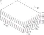
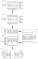
图1为软性排线的第一实施例的示意图。FIG. 1 is a schematic diagram of a first embodiment of a flexible flat cable.
图2为图1中切线I-I的断面示意图。FIG. 2 is a schematic cross-sectional view of the tangent line I-I in FIG. 1 .
图3为软性排线的第二实施例的示意图。FIG. 3 is a schematic diagram of a second embodiment of the flexible flat cable.
图4为图3中切线II-II的断面示意图。FIG. 4 is a schematic cross-sectional view of the line II-II in FIG. 3 .
图5为软性排线的第三实施例的示意图。FIG. 5 is a schematic diagram of a third embodiment of a flexible flat cable.
图6为图5中切线III-III的断面示意图。FIG. 6 is a schematic cross-sectional view taken along the line III-III in FIG. 5 .
图7为软性排线的第四实施例的示意图。FIG. 7 is a schematic diagram of a fourth embodiment of a flexible flat cable.
图8为图7中切线IV-IV的断面示意图。FIG. 8 is a schematic cross-sectional view of the line IV-IV in FIG. 7 .
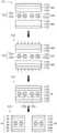
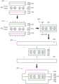
图9为软性排线的制造方法的第一实施例的流程图。FIG. 9 is a flow chart of the first embodiment of the manufacturing method of the flexible flat cable.
图10为软性排线的制造方法的第二实施例的流程图。FIG. 10 is a flow chart of the second embodiment of the manufacturing method of the flexible flat cable.
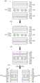
图11为软性排线的制造方法的第三实施例的流程图。FIG. 11 is a flow chart of a third embodiment of a manufacturing method of a flexible flat cable.
图12为软性排线的制造方法的第四实施例的流程图。FIG. 12 is a flowchart of a fourth embodiment of a manufacturing method of a flexible flat cable.
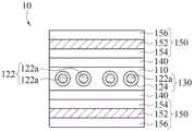
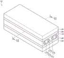
图13为软性排线的第五实施例的示意图。FIG. 13 is a schematic diagram of a fifth embodiment of a flexible flat cable.
图14为图13中切线V-V的一示范例的断面示意图。FIG. 14 is a schematic cross-sectional view of an example of the tangent line V-V in FIG. 13 .
图15为图13中切线V-V的另一示范例的断面示意图。FIG. 15 is a schematic cross-sectional view of another example of the tangent line V-V in FIG. 13 .
图16为软性排线的第六实施例的示意图。FIG. 16 is a schematic diagram of a sixth embodiment of the flexible flat cable.
图17为图16中切线VI-VI的一示范例的断面示意图。FIG. 17 is a schematic cross-sectional view of an example of the tangent line VI-VI in FIG. 16 .
图18为图16中切线VI-VI的另一示范例的断面示意图。FIG. 18 is a schematic cross-sectional view of another example of the tangent line VI-VI in FIG. 16 .
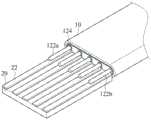
图19为软性排线的第七实施例的示意图。FIG. 19 is a schematic diagram of a seventh embodiment of a flexible flat cable.
图20为图19中切线VII-VII的一示范例的断面示意图。FIG. 20 is a schematic cross-sectional view of an example of the tangent line VII-VII in FIG. 19 .
图21为图19中切线VII-VII的另一示范例的断面示意图。FIG. 21 is a schematic cross-sectional view of another example along the line VII-VII in FIG. 19 .
图22为软性排线的第八实施例的示意图。FIG. 22 is a schematic diagram of an eighth embodiment of a flexible flat cable.
图23为图22中切线VIII-VIII的一示范例的断面示意图。FIG. 23 is a schematic cross-sectional view of an example of the tangent line VIII-VIII in FIG. 22 .
图24为图22中切线VIII-VIII的另一示范例的断面示意图。FIG. 24 is a schematic cross-sectional view of another example of the tangent line VIII-VIII in FIG. 22 .
图25及图26为具有第一示范形式的屏蔽层的软性排线的断面示意图。25 and 26 are schematic cross-sectional views of a flexible flat cable having a shielding layer of a first exemplary form.
图27为软性排线的制造方法的第五实施例的流程图。FIG. 27 is a flow chart of the fifth embodiment of the manufacturing method of the flexible flat cable.
图28为软性排线的制造方法的第六实施例的流程图。FIG. 28 is a flowchart of the sixth embodiment of the manufacturing method of the flexible flat cable.
图29为软性排线的制造方法的第七实施例的流程图。FIG. 29 is a flowchart of a seventh embodiment of a method for manufacturing a flexible flat cable.
图30及图31为具有第二示范形式的屏蔽层的软性排线的断面示意图。30 and 31 are schematic cross-sectional views of a flexible flat cable having a second exemplary form of shielding layer.
图32为软性排线的制造方法的第八实施例的流程图。FIG. 32 is a flow chart of the eighth embodiment of the manufacturing method of the flexible flat cable.
图33及图34为具有第三示范形式的屏蔽层的软性排线的断面示意图。33 and 34 are schematic cross-sectional views of a flexible flat cable having a shielding layer of a third exemplary form.
图35及图36为具有第四示范形式的屏蔽层的软性排线的断面示意图。35 and 36 are schematic cross-sectional views of a flexible flat cable having a fourth exemplary form of shielding layer.
图37为软性排线的制造方法的第九实施例的流程图。FIG. 37 is a flow chart of the ninth embodiment of the manufacturing method of the flexible flat cable.
图38为软性排线的第一应用例的示意图。FIG. 38 is a schematic diagram of a first application example of the flexible flexible cable.
图39为软性排线的第二应用例的示意图。FIG. 39 is a schematic diagram of a second application example of the flexible flexible cable.
其中,附图标记where the reference number
10 软性排线10 flexible cable
110 第一绝缘层110 first insulating layer
122 导线对122 wire pairs
122a 导线122a wire
122b 导线122b wire
124 低介电常数(K)介电层124 Low dielectric constant (K) dielectric layer
130 具有外披的导线130 Conductor with overcoat
132 具有外披的导线对132 Conductor pairs with overcoat
140 第二绝缘层140 Second insulating layer
150 屏蔽层150 shield
152 金属层152 Metal Layers
154 黏着层154 Adhesive layer
156 第三绝缘层156 Third insulating layer
158 外介电层158 Outer Dielectric Layer
160 绝缘屏蔽膜160 Insulation Shielding Film
170 绝缘膜170 insulating film
20 电路板20 circuit boards
22 电路22 circuits
30 电连接器组件30 Electrical Connector Assembly
I-I 切线I-I Tangent
II-II 切线II-II Tangent
III-III 切线III-III Tangent
IV-IV 切线IV-IV Tangent
V-V 切线V-V Tangent
VI-VI 切线VI-VI Tangent
VII-VII 切线VII-VII Tangent
VIII-VIII 切线VIII-VIII Tangent
S11~S14 步骤Steps S11~S14
S21~S24 步骤Steps S21~S24
S51~S56 步骤Steps S51~S56
S61~S65 步骤Steps from S61 to S65
S71~S75 步骤S71~S75 steps
S81~S85 步骤S81~S85 steps
具体实施方式Detailed ways
下面结合附图和具体实施例对本实用新型技术方案进行详细的描述,以更进一步了解本实用新型的目的、方案及功效,但并非作为本实用新型所附权利要求保护范围的限制。The technical solutions of the present utility model are described in detail below in conjunction with the accompanying drawings and specific embodiments, so as to further understand the purpose, solutions and effects of the present utility model, but are not intended to limit the protection scope of the appended claims of the present utility model.
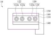
在一些实施例中,参照图1至图4,软性排线(flexible flat cable,FFC)10包括:一第一绝缘层110、至少一导线对122、多个低介电常数(K)介电层124、二金属层(metallayer)152、以及二外介电层158。In some embodiments, referring to FIGS. 1 to 4 , a flexible flat cable (FFC) 10 includes: a first insulating
于此,每一导线对122具有相邻的二导线(以下称第一导线122a)。此些第一导线122a纵向延伸且平行配置。换言之,各第一导线122a沿着第一方向延伸,并且此些第一导线122a沿着第二方向平行排列。其中,第一方向大致上垂直于第二方向。Here, each
在一实施例中,低介电常数介电层124分别包覆在第一导线122a的外侧,如图1及图2所示。换言之,每一第一导线122a环绕轴心的表面上覆盖有一层低介电常数介电层124,藉以形成具有外披(jacket)的导线130。并且,具有外披的导线130嵌设在第一绝缘层110内。在一示范例中,具有外披的导线130彼此之间间隔排列。换言之,相邻二具有外披的导线130之间存在有间隙。In one embodiment, the low-k dielectric layers 124 respectively cover the outer sides of the
在另一实施例中,低介电常数介电层124分别包覆在导线对122的外侧,如图3及图4所示。换言之,每一导线对122的外侧覆盖有一层低介电常数介电层124,藉以形成具有外披的导线对132。并且,具有外披的导线对132的导线130嵌设在第一绝缘层110内。在一示范例中,此些低介电常数介电层124个别纵向延伸,且彼此平行且间隔排列。而每一导线对122则嵌在对应的低介电常数介电层124的内部。换言之,相邻二具有外披的导线对132之间存在有间隙。In another embodiment, the low-k dielectric layers 124 are respectively coated on the outer sides of the wire pairs 122 , as shown in FIG. 3 and FIG. 4 . In other words, the outer side of each
再参照回图1至图4,二外介电层158分别位于第一绝缘层110的二表面上。二金属层152相对第一绝缘层110分别位于二外介电层158上。Referring back to FIGS. 1 to 4 , the two outer
在一些实施例中,第一绝缘层110、外介电层158与金属层152能以二绝缘屏蔽膜实现。其中,此绝缘屏蔽膜可例如绝缘屏蔽卷带(insulating-shielding tape)。举例来说,一部份的第一绝缘层110、一外介电层158与一金属层152形成一卷带,而另一部份的第一绝缘层110、另一外介电层158与另一金属层152形成另一卷带。换言之,软性排线10的最外层为金属层152。In some embodiments, the first insulating
在一些实施例中,软性排线10可更包括:二第二绝缘层140。二第二绝缘层140分别相对二外介电层158位于二金属层152上。In some embodiments, the flexible
在一些实施例中,第一绝缘层110、外介电层158、金属层152与第二绝缘层140能以二绝缘屏蔽膜实现。其中,此绝缘屏蔽膜可例如绝缘屏蔽卷带。举例来说,一部份的第一绝缘层110、一外介电层158、一金属层152与一第二绝缘层140形成一卷带,而另一部份的第一绝缘层110、另一外介电层158、另一金属层152与另一第二绝缘层140形成另一卷带。换言之,软性排线10的最外层为第二绝缘层140,以保护内部结构。In some embodiments, the first insulating
在一些实施例中,软性排线10可更包括:无被低介电常数介电层124包覆且环绕的至少一导线(第二导线122b),即无外披的导线,如图5至图8所示。第二导线122b轴向延伸且与导线对122平行排列。第二导线122b直接嵌设在第一绝缘层110内。于此,导线对122与第二导线122b交错且间隔配置。在一些实施例中,从软性排线10的断面来看,最接近软性排线10的二侧边的二导线为第二导线122b,即无外披的导线。In some embodiments, the flexible
在一些实施例中,金属层152可为金属薄片(metal foil)或金属镀膜。在一些实施例中,金属层152能以干式贴合、湿式贴合或蒸镀的方式形成在第二绝缘层140的表面。In some embodiments, the
在一些实施例中,外介电层158能以干式贴合、湿式贴合或涂布(coating)的方式形成在金属层152邻近第一绝缘层110的表面,即金属层152相对于第二绝缘层140另一侧的表面。In some embodiments, the
在一些实施例中,第一绝缘层110为热熔性(hot melt)。在一些实施例中,第一绝缘层110能以湿式贴合或涂布的方式形成在外介电层158的表面。In some embodiments, the first insulating
在一些实施例中,参照图9及图10,软性排线10的制造方法如下。首先,平行排列至少一导线对122(即,多个具有外披的导线130或至少一具外披的导线对(132,图未示))在二绝缘屏蔽膜160之间(步骤S11或S21)。在一实施例中,各绝缘屏蔽膜包括一金属层152、靠近至少一导线对122地位于金属层152上的一外介电层158、以及靠近至少一导线对122地位于外介电层158上的一热熔性绝缘层(即一部分的第一绝缘层110),如图9所示。在一实施例中,各绝缘屏蔽膜包括一第二绝缘层140、一金属层152、靠近至少一导线对122地位于金属层152上的一外介电层158、以及靠近至少一导线对122地位于外介电层158上的一热熔性绝缘层(即一部分的第一绝缘层110)。In some embodiments, referring to FIG. 9 and FIG. 10 , the manufacturing method of the flexible
于步骤S11或S21后,接着,热压合(laminating)二绝缘屏蔽膜160为一绝缘屏蔽层(步骤S12或S22),以使具有外披的导线130或具外披的导线对(132)嵌设绝缘屏蔽层中,即形成软性排线(步骤S13或S23)。在一示范例中,二绝缘屏蔽膜160邻近导线122a的一侧为热熔性的第一绝缘层110,因此在热压步骤(步骤S11或S21)中,二绝缘屏蔽膜160的第一绝缘层110会因热压而融合成一层,并将具有外披的导线130或具外披的导线对(132)(及无外披的导线122b,图未示)嵌设于其中。After the step S11 or S21, then, the two insulating shielding
在一些实施例中,可藉由前述步骤S11~S12或S21~S22一次性形成具有大量导线对122的一大块软性排线,即边缘(即,沿着导线122a延伸的侧边)相互耦接的多条软性排线10,然后依据每条软性排线10所需的导线122a(及无外披的导线122b,图未示)的数量进行切割(即,将相邻二导线122a之间切断)以分离为多条软性排线10(步骤S13或S23),如图11及图12所示。In some embodiments, a large piece of flexible flexible cable with a large number of wire pairs 122 can be formed at one time by the aforementioned steps S11-S12 or S21-S22, that is, the edges (ie, the sides extending along the
在一些实施例中,于步骤S11或S21前,可先形成各绝缘屏蔽膜160。In some embodiments, each insulating
在一示范例中,绝缘屏蔽膜160的形成步骤包括外介电层158以干式贴合、湿式贴合或涂布等方式形成在金属层152的表面上,以及第一绝缘层110以湿式贴合或涂布等的方式形成在外介电层158相对于金属层152的另一侧的表面上。其中,第一绝缘层110为热熔性材料。In an exemplary example, the forming step of the insulating
在另一示范例中,绝缘屏蔽膜160的形成步骤包括金属层152以干式贴合、湿式贴合或蒸镀等方式形成在第二绝缘层140的表面、外介电层158以干式贴合、湿式贴合或涂布等方式形成在金属层152相对于第二绝缘层140的另一侧的表面上,以及第一绝缘层110以湿式贴合或涂布等的方式形成在外介电层158相对于金属层152的另一侧的表面上。其中,第一绝缘层110为热熔性材料。In another example, the step of forming the insulating
其中,若金属层152以干式贴合或湿式贴合方式形成,金属层152可为一金属薄片。若金属层152以蒸镀方式形成,金属层152可为一金属镀膜。Wherein, if the
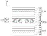
在一些实施例中,参照图13至图18,软性排线10包括:一第一绝缘层110、至少一导线对122、多个低介电常数(K)介电层124、二第二绝缘层140、以及至少一屏蔽层150。其中,各屏蔽层150为复合层。In some embodiments, referring to FIGS. 13 to 18 , the flexible
于此,每一导线对122具有二第一导线122a。此些第一导线122a纵向延伸且平行配置。换言之,各第一导线122a沿着第一方向延伸,并且此些第一导线122a沿着第二方向平行排列。其中,第一方向大致上垂直于第二方向。Here, each
在一些实施例中,低介电常数介电层124分别包覆在第一导线122a的外侧,如图13至图15所示。换言之,每一第一导线122a环绕轴心的表面上覆盖有一层低介电常数介电层124,藉以形成具有外披(jacket)的导线130。并且,具有外披的导线130嵌设在第一绝缘层110内。在一示范例中,具有外披的导线130彼此之间间隔排列。换言之,相邻二具有外披的导线130之间存在有间隙。In some embodiments, the low-k dielectric layers 124 respectively coat the outer sides of the
在另一些实施例中,低介电常数介电层124分别包覆在导线对122的外侧,如图16至图18所示。换言之,每一导线对122的外侧覆盖有一层低介电常数介电层124,藉以形成具有外披的导线对132。并且,具有外披的导线对132的导线130嵌设在第一绝缘层110内。在一示范例中,此些低介电常数介电层124个别纵向延伸,且彼此平行且间隔排列。而每一导线对122则嵌在对应的低介电常数介电层124的内部。换言之,相邻二具有外披的导线对132之间存在有间隙。In other embodiments, the low-k dielectric layers 124 are respectively coated on the outer sides of the wire pairs 122 , as shown in FIG. 16 to FIG. 18 . In other words, the outer side of each
二第二绝缘层140分别位在第一绝缘层110的二表面上。屏蔽层150则相对第一绝缘层110位于第二绝缘层140上。Two second insulating
在一些实施例中,参照图14及图17,以屏蔽层150为二个为例,二屏蔽层150相对第一绝缘层110分别位于第二绝缘层140上。各屏蔽层150包括一金属层152、一黏着层154以及一第三绝缘层156。金属层152相对第一绝缘层110位于对应的第二绝缘层140上。黏着层154用以黏合相邻的金属层152与第二绝缘层140。第三绝缘层156相对于第二绝缘层140位于对应的金属层152上,以保护内部结构。举例来说,对于一软性排线10来说,从中间的第一绝缘层110向外依序层叠第二绝缘层140、黏着层154、金属层152与第三绝缘层156。In some embodiments, referring to FIGS. 14 and 17 , taking two shielding
在一些实施例中,参照图15及图18,以屏蔽层150为二个为例,二屏蔽层150相对第一绝缘层110分别位于第二绝缘层140上。各屏蔽层150包括一外介电层158、一金属层152以及一黏着层154。外介电层158相对第一绝缘层110位于对应的第二绝缘层140上。黏着层154用以黏合相邻的外介电层158与第二绝缘层140。金属层152相对于第二绝缘层140位于对应的外介电层158。举例来说,对于一软性排线10来说,从中间的第一绝缘层110向外依序层叠第二绝缘层140、黏着层154、外介电层158、与金属层152。于此,软性排线10的最外侧无第三绝缘层156保护。In some embodiments, referring to FIGS. 15 and 18 , taking two shielding
在一些实施例中,各屏蔽层150可更包括一第三绝缘层156。在一示范例中,此第三绝缘层156相对于黏着层154位于对应的金属层152上,以提供保护。举例来说,对于一软性排线10来说,从中间的第一绝缘层110向外依序层叠第二绝缘层140、黏着层154、外介电层158、金属层152与第三绝缘层156。于此,软性排线10的最外侧设置第三绝缘层156,以保护内部结构。在另一示范例中,第三绝缘层156可设置在金属层152与外介电层158之间(图未示)。换言之,第三绝缘层156相对于第二绝缘层140位于对应的外介电层158。金属层152相对于黏着层154位于对应的第三绝缘层156上。举例来说,对于一软性排线10来说,从中间的第一绝缘层110向外依序层叠第二绝缘层140、黏着层154、外介电层158、第三绝缘层156、与金属层152。于此,第三绝缘层156用以调整金属层152与导线122a之间的绝对距离,以提供较佳的信号屏蔽效果。In some embodiments, each
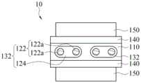
在一些实施例中,软性排线10可更包括:无被低介电常数介电层124包覆且环绕的至少一导线(第二导线122b),即无外披的导线,如图19至图24所示。第二导线122b轴向延伸且与导线对122平行排列。第二导线122b直接嵌设在第一绝缘层110内。于此,导线对122与第二导线122b交错且间隔配置。在一些实施例中,从软性排线10的断面来看,最接近软性排线10的二侧边的二导线为第二导线122b,即无外披的导线。In some embodiments, the flexible
在一些实施例中,金属层152可为金属薄片或金属镀膜。在一些实施例中,金属层152可以干式贴合、湿式贴合或蒸镀的方式形成在第三绝缘层156的表面。In some embodiments, the
在一些实施例中,外介电层158可以干式贴合、湿式贴合或涂布的方式形成在金属层152或第三绝缘层156邻近第一绝缘层110的表面。In some embodiments, the
在一些实施例中,黏着层154以转贴、湿式贴合或涂布等的方式形成在外介电层158或金属层152的表面。在一些实施例中,此黏着层154可为一介电黏着层。In some embodiments, the
在一些实施例中,第一绝缘层110为热熔性。在一些实施例中,第一绝缘层110可以湿式贴合或涂布的方式形成在第二绝缘层140的表面。In some embodiments, the first insulating
在一些实施例中,若屏蔽层150为二个,屏蔽层150的宽度可大致上相等于第二绝缘层140的宽度,即屏蔽层150、第二绝缘层140与第一绝缘层110的边缘切齐,如图13至图24所示。在一些实施例中,若屏蔽层150为二个,第二绝缘层140的宽度能超过屏蔽层150的宽度,即,就软性排线10的截面来看,第二绝缘层140(与第一绝缘层110)的二侧边分别超过各屏蔽层150的二侧边,以使各屏蔽层150相对于第二绝缘层140内缩,如图25及图26所示。In some embodiments, if there are two shielding
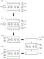
在一些实施例中,若软性排线10的边缘为切齐或其屏蔽层150内缩,此软性排线10可如下列方法制作,如图27及图28所示。参照图27及图28,首先,平行排列至少一导线对122(即,多个具有外披的导线130或至少一具外披的导线对(132,图未示))在二绝缘膜170之间(步骤S51或S61)。其中,各绝缘膜170包括一第一绝缘层110与一第二绝缘层140。第一绝缘层110邻近导线对122地层叠于第二绝缘层140上,即覆盖在第二绝缘层140的内表面。于此,第一绝缘层110为热熔性。In some embodiments, if the edges of the flexible
于步骤S51或S61之后,热压合二绝缘膜170为一绝缘层(步骤S52或S62),以使具有外披的导线130或具外披的导线对(132)嵌设绝缘层中(步骤S53或S63)。于此,在热压步骤中,二绝缘膜170内侧的第一绝缘层110会因热压而融合成一层,并将具有外披的导线130或具外披的导线对(132)(及无外披的导线122b,图未示)嵌设于其中。After step S51 or S61, the two insulating
于步骤S53或S63之后,再将二屏蔽膜(即屏蔽层150)相对导线对122分别贴合在二绝缘膜170的二外表面上(步骤S54或S64),以形成软性排线10(步骤S55或S65)。换言之,二屏蔽膜(即屏蔽层150)相对第一绝缘层110分别贴合在二第二绝缘层140上。在一示范例中,各屏蔽膜(即屏蔽层150)与绝缘膜170(即第一绝缘层110与第二绝缘层140)切齐,如图27所示。在另一示范例中,就软性排线10的截面来看,绝缘膜170(即第一绝缘层110与第二绝缘层140)的二侧边,各屏蔽膜(即屏蔽层150)的二侧边向内缩,即,各屏蔽膜(即屏蔽层150)的宽度小于绝缘膜170(即第一绝缘层110与第二绝缘层140)的宽度,如图28所示。其中,各屏蔽膜(即屏蔽层150)的层叠结构如前述实施例所述,故不再赘述。After step S53 or S63 , the two shielding films (ie, the shielding layers 150 ) are respectively attached to the two outer surfaces of the two insulating
在一些实施例中,可藉由前述步骤S51~S55一次性形成具有大量导线对122的一大块软性排线10,即边缘(即,沿着导线122a延伸的侧边)相互耦接的多条软性排线10,然后依据每条软性排线10所需的导线122a的数量进行切割(即,将相邻二导线122a之间切断)以分离为多条软性排线10(步骤S56),如图29所示。In some embodiments, a large piece of flexible
在一些实施例中,若屏蔽层150为二个,屏蔽层150的宽度能超过第二绝缘层140的宽度,即,就软性排线10的截面来看,各屏蔽层150的二侧边分别超过第二绝缘层140(与第一绝缘层110)的二侧边,以使各屏蔽层150相对于第二绝缘层140外凸,如图30及图31所示。In some embodiments, if there are two shielding
在一些实施例中,若软性排线10的屏蔽层150外凸,此软性排线10可如下列方法制作,如图32所示。参照图32,首先,平行排列至少一导线对122(即,多个具有外披的导线130或至少一具外披的导线对(132,图未示))在二绝缘膜170之间(步骤S71)。其中,各绝缘膜170包括一第一绝缘层110与一第二绝缘层140。第一绝缘层110邻近导线对122地层叠于第二绝缘层140上,即覆盖在第二绝缘层140的内表面。于此,第一绝缘层110为热熔性。In some embodiments, if the
于步骤S71之后,热压合二绝缘膜170为一绝缘层(步骤S72),以使具有外披的导线130或具外披的导线对(132)嵌设绝缘层中(步骤S73)。于此,在热压步骤中,二绝缘膜170内侧的第一绝缘层110会因热压而融合成一层,并将具有外披的导线130或具外披的导线对(132)(及无外披的导线122b,图未示)嵌设于其中。After step S71 , the two insulating
于步骤S73之后,再将二屏蔽膜(即屏蔽层150)相对导线对122分别贴合在二绝缘膜170的二外表面上,并将二屏蔽膜(即屏蔽层150)超出绝缘膜170(即绝缘层)的区段相互贴合(步骤S74),以形成软性排线10(步骤S75)。换言之,二屏蔽膜(即屏蔽层150)相对第一绝缘层110分别贴合在二第二绝缘层140上。其中,二屏蔽膜(即屏蔽层150)的一端超出绝缘膜170(即绝缘层)的区段相互贴合在一起,并且二屏蔽膜(即屏蔽层150)的另一端超出绝缘膜170(即绝缘层)的区段相互贴合在一起。于此,各屏蔽膜(即屏蔽层150)的层叠结构如前述实施例所述,故不再赘述。After step S73 , the two shielding films (ie, the shielding layers 150 ) are respectively attached to the two outer surfaces of the second insulating
在一些实施例中,若屏蔽层150为一个,屏蔽层150可环绕并包覆二第二绝缘层140,即,屏蔽层150成环包状,如图33及图34所示。换言之,屏蔽层150环绕且覆盖在第二绝缘层140、第一绝缘层110与第二绝缘层140依序叠合的复合层结构上。在一示范例中,屏蔽层150环绕前述的复合层结构后,屏蔽层150的二端相互接合在一起,如图33及图34所示。在另一示范例中,屏蔽层150环绕前述的复合层结构后,屏蔽层150的二端会交叠贴合,如图35及图36所示。In some embodiments, if there is one
在一些实施例中,若软性排线10的屏蔽层150呈环包状,此软性排线10可如下列方法制作,如图37所示。参照图37,首先,平行排列至少一导线对122(即,多个具有外披的导线130或至少一具外披的导线对(132,图未示))在二绝缘膜170之间(步骤S81)。其中,各绝缘膜170包括一第一绝缘层110与一第二绝缘层140。第一绝缘层110邻近导线对122地层叠于第二绝缘层140上,即覆盖在第二绝缘层140的内表面。于此,第一绝缘层110为热熔性。In some embodiments, if the
于步骤S81之后,热压合二绝缘膜170为一绝缘层(步骤S82),以使具有外披的导线130或具外披的导线对(132)嵌设绝缘层中(步骤S83)。于此,在热压步骤中,二绝缘膜170内侧的第一绝缘层110会因热压而融合成一层,并将具有外披的导线130或具外披的导线对(132)(及无外披的导线122b,图未示)嵌设于其中。After step S81 , the two insulating
于步骤S83之后,再将一屏蔽膜(即屏蔽层150)环绕绝缘层(即第二绝缘层140、第一绝缘层110与第二绝缘层140依序叠合的复合层结构)一圈并贴合在此绝缘层上(步骤S84),以形成软性排线(步骤S85)。于此,屏蔽膜(即屏蔽层150)的层叠结构如前述实施例所述,故不再赘述。After step S83 , a shielding film (ie, the shielding layer 150 ) is then wrapped around the insulating layer (ie, the composite layer structure in which the second insulating
在一些实施例中,于步骤S51、S61、S71或S81之前,可先形成各绝缘膜170。在一些实施例中,各绝缘膜170的形成步骤包括第一绝缘层110以湿式贴合或涂布等的方式形成在第二绝缘层140的表面上。其中,第一绝缘层110为热熔性材料。In some embodiments, each insulating
在一些实施例中,前述的湿式贴合可例如挤型(extrusion)。In some embodiments, the aforementioned wet lamination may be, for example, extrusion.
在一些实施例中,前述的导线122a、122b的材质可为铝(Al)、铜(Cu)、金(Au)、银(Ag)、或多层金属等。在一些实施例中,多层金属的导线122a、122b可例如为导线122a、122b本身为铜但外层镀下列金属中至少一者:锡、镍、合金、银、金、铝等。In some embodiments, the
在一些实施例中,各导线112a、112b可为实心导线(solid conductor)(如单芯线)或绞合导线(stranded conductor)(如多芯线)。在一些实施例中,各导线112a、112b的横截面的外形可为圆形、扁圆形、椭圆形、矩形或斜角矩形。其中,各导线112a、112b的横截面大致上垂直于其轴心。在一些实施例中,矩形或斜角矩形的导线112a、112b的断面的宽高比可为6:1。In some embodiments, each conductor 112a, 112b may be a solid conductor (eg, a single conductor) or a stranded conductor (eg, a multiple conductor). In some embodiments, the shape of the cross-section of each wire 112a, 112b may be circular, oblate, oval, rectangular, or beveled rectangle. Wherein, the cross section of each wire 112a, 112b is substantially perpendicular to its axis. In some embodiments, the cross-sections of the rectangular or beveled rectangular wires 112a, 112b may have an aspect ratio of 6:1.
举例来说,各导线112a、112b可为但不限于圆形实心导线、圆形绞合导线、扁圆形实心导线、扁圆形绞合导线、椭圆形实心导线、椭圆形绞合导线、矩形实心导线、矩形绞合导线、斜角矩形实心导线或斜角矩形绞合导线等。For example, each wire 112a, 112b can be, but is not limited to, round solid wire, round stranded wire, flat round solid wire, flat round stranded wire, oval solid wire, oval stranded wire, rectangular Solid wire, rectangular stranded wire, beveled rectangular solid wire or beveled rectangular stranded wire, etc.
在一些实施例中,前述的低介电常数介电层124的材质、前述的第一绝缘层110的材质、前述的第二绝缘层140的材质、前述的黏着层154的材质、前述的外介电层158的材质、及前述的第三绝缘层156的材质可为高分子聚合物。In some embodiments, the material of the aforementioned low-
在一些实施例中,低介电常数介电层124的材质可为耐温材料。于此,低介电常数介电层124的熔(melt)点高于第一绝缘层110的熔点。In some embodiments, the material of the low-
在一些实施例中,低介电常数介电层124的介电常数低于最外层的绝缘层(即,图1至图8所示的第二绝缘层140或图13至图24所示的第三绝缘层156)。在一些实施例中,低介电常数介电层124的介电常数低于2.5。其中,低介电常数介电层124的材质可为FEP(氟化乙烯丙烯共聚物(又称全氟乙烯丙烯共聚物或聚全氟乙丙烯),Fluorinated ethylenepropylene)、PP(聚丙烯,Polypropylene)、PO(聚烯,Polyolefin)、PE(聚乙烯,Polyethene)、或LCP(液晶高分子聚合物,Liquid Crystal Polymer)等。In some embodiments, the low-
在一些实施例中,低介电常数介电层124可藉由发泡技术形成微气泡于其中。在一些实施例中,低介电常数介电层124中的微气泡内的介质可为空气。In some embodiments, the low-
在一些实施例中,导线122a的边缘到低介电常数介电层124的外缘之间的最短距离小于或等于导线122a的半径。In some embodiments, the shortest distance from the edge of the
在一些实施例中,前述的第一绝缘层110的材质可为PO、TPE、或TPU等。较佳地,第一绝缘层110的材质可为低介电材料。其中,第一绝缘层110的介电常数可低于2.5。In some embodiments, the material of the aforementioned first insulating
在一些实施例中,图13至图24所示的第二绝缘层140的材质可为PET、FEP、PPS(聚苯硫醚,Polyphenylene sulfide)或LCP等。较佳地,图13至图24所示的第二绝缘层140的材质可为低介电材料。其中,且图13至图24所示的第二绝缘层140的介电常数可低于2.5。In some embodiments, the material of the second insulating
在一些实施例中,前述的黏着层154的材质的主成分可为PET、arcrilic、silicone、PP、PO、TPE、或TPU等。较佳地,黏着层154的材质的主成分可为低介电材料,如PP、PO、TPE、或TPU等。其中,黏着层154的介电常数可低于2.5。In some embodiments, the main component of the material of the aforementioned
在一些实施例中,前述的外介电层158的材质可为PET、arcrilic、silicone、PP、PO、TPE、或TPU等。较佳地,外介电层158的材质可为低介电材料,如PP、PO、TPE、或TPU等。其中,外介电层158的介电常数可低于2.5。In some embodiments, the material of the aforementioned outer
在一些实施例中,具有外披的导线130或具有外披的导线对132能适用于高速信号传输。换言之,具有外披的导线130或具有外披的导线对132能用以以高速传输信号。在一些实施例中,具有外披的导线130或具有外披的导线对132用以传输信号的速率可等于或大于10Gbps。In some embodiments, the
再者,无外披的导线122b则适用于非高速信号传输。举例来说,无外披的导线122b可用以传输电力或接地。Furthermore, the
在一些实施例中,软性排线10可只包括具有外披的导线130或只具有外披的导线对132,而不包括无外披的导线122b。于此,软性排线10中的导线112a能以等距间隔排列。In some embodiments, the flexible
在一些实施例中,软性排线10可包括具有外披的导线130或只具有外披的导线对132,以及包括无外披的导线122b。于此,软性排线10中的导线112a、112b能以等距间隔排列。In some embodiments, the flexible
在一些实施例中,参照图38,前述任一实施例的软性排线10的导线112a、112b能直接焊接于电路板20上,以使导线112a、112b电性连接电路板20上的电路22。In some embodiments, referring to FIG. 38 , the wires 112 a and 112 b of the flexible
在一些实施例中,参照图39,前述任一实施例的软性排线10的一端或二端可耦接电连接器组件30,以构成信号传输线(即信号传输装置)。于此,软性排线10的导线112a、112b电连接电连接器组件30的导电端子。In some embodiments, referring to FIG. 39 , one or both ends of the flexible
综上所述,根据本实用新型的软性排线、其制造方法及信号传输装置,其将夹设在绝缘层(即第一绝缘层110)中的导线112a披覆一层低介电材料(即低介电常数介电层124),以避免高介电材料对信号传输的影响,进而相对提升高速信号传输品质。并且,根据本实用新型的实施例,其制程方便且成本低。To sum up, according to the flexible flat cable, the manufacturing method and the signal transmission device of the present invention, the wires 112a sandwiched in the insulating layer (ie, the first insulating layer 110 ) are coated with a layer of low-dielectric material (ie, the low-k dielectric layer 124 ) to avoid the influence of high-k materials on signal transmission, thereby relatively improving the quality of high-speed signal transmission. Moreover, according to the embodiment of the present invention, the manufacturing process is convenient and the cost is low.
当然,本实用新型还可有其它多种实施例,在不背离本实用新型精神及其实质的情况下,熟悉本领域的技术人员当可根据本实用新型作出各种相应的改变和变形,但这些相应的改变和变形都应属于本实用新型所附的权利要求的保护范围。Of course, the present utility model can also have other various embodiments, without departing from the spirit and essence of the present utility model, those skilled in the art can make various corresponding changes and deformations according to the present utility model, but These corresponding changes and deformations should all belong to the protection scope of the appended claims of the present invention.
Claims (18)
Translated fromChineseApplications Claiming Priority (4)
| Application Number | Priority Date | Filing Date | Title |
|---|---|---|---|
| US201962880678P | 2019-07-31 | 2019-07-31 | |
| US62/880,678 | 2019-07-31 | ||
| TW108140535 | 2019-11-07 | ||
| TW108140535ATW202107495A (en) | 2019-07-31 | 2019-11-07 | Flexible flat cable (ffc), making method thereof and signal transmission device |
Publications (1)
| Publication Number | Publication Date |
|---|---|
| CN211479699Utrue CN211479699U (en) | 2020-09-11 |
Family
ID=72141835
Family Applications (2)
| Application Number | Title | Priority Date | Filing Date |
|---|---|---|---|
| CN201911283023.7AActiveCN112309617B (en) | 2019-07-31 | 2019-12-13 | Flexible flat cable, manufacturing method thereof and signal transmission device |
| CN201922237409.6UActiveCN211479699U (en) | 2019-07-31 | 2019-12-13 | Flexible flat cable and signal transmission device |
Family Applications Before (1)
| Application Number | Title | Priority Date | Filing Date |
|---|---|---|---|
| CN201911283023.7AActiveCN112309617B (en) | 2019-07-31 | 2019-12-13 | Flexible flat cable, manufacturing method thereof and signal transmission device |
Country Status (2)
| Country | Link |
|---|---|
| US (2) | US11710582B2 (en) |
| CN (2) | CN112309617B (en) |
Families Citing this family (2)
| Publication number | Priority date | Publication date | Assignee | Title |
|---|---|---|---|---|
| CN115424765A (en)* | 2022-05-10 | 2022-12-02 | 东莞市晟合科技有限公司 | Ultra-high-speed transmission line |
| CN219761418U (en)* | 2023-03-13 | 2023-09-26 | 深圳市和鑫晟智连科技有限公司 | FPC winding displacement and data line |
Family Cites Families (46)
| Publication number | Priority date | Publication date | Assignee | Title |
|---|---|---|---|---|
| US3612744A (en)* | 1969-02-27 | 1971-10-12 | Hughes Aircraft Co | Flexible flat conductor cable of variable electrical characteristics |
| US4185162A (en)* | 1978-01-18 | 1980-01-22 | Virginia Plastics Company | Multi-conductor EMF controlled flat transmission cable |
| US4287385A (en)* | 1979-09-12 | 1981-09-01 | Carlisle Corporation | Shielded flat cable |
| US4475006A (en)* | 1981-03-16 | 1984-10-02 | Minnesota Mining And Manufacturing Company | Shielded ribbon cable |
| US4468089A (en)* | 1982-07-09 | 1984-08-28 | Gk Technologies, Inc. | Flat cable of assembled modules and method of manufacture |
| JPH0614326Y2 (en)* | 1988-10-24 | 1994-04-13 | 住友電気工業株式会社 | Flat cable with shield |
| US5084594A (en)* | 1990-08-07 | 1992-01-28 | Arrowsmith Shelburne, Inc. | Multiwire cable |
| US5162609A (en)* | 1991-07-31 | 1992-11-10 | At&T Bell Laboratories | Fire-resistant cable for transmitting high frequency signals |
| US5900588A (en)* | 1997-07-25 | 1999-05-04 | Minnesota Mining And Manufacturing Company | Reduced skew shielded ribbon cable |
| US6300846B1 (en)* | 1999-03-18 | 2001-10-09 | Molex Incorporated | Flat flexible cable with ground conductors |
| JP2001297633A (en)* | 2000-04-12 | 2001-10-26 | Hirakawa Hewtech Corp | Foam insulated wire |
| JP5247956B2 (en) | 2001-03-19 | 2013-07-24 | 大日本印刷株式会社 | Flat cable shield material and shielded flat cable |
| JP4066725B2 (en) | 2002-06-26 | 2008-03-26 | 日立電線株式会社 | Manufacturing method for shielded flexible flat cable |
| US7737359B2 (en)* | 2003-09-05 | 2010-06-15 | Newire Inc. | Electrical wire and method of fabricating the electrical wire |
| JP2008198592A (en)* | 2007-01-18 | 2008-08-28 | Sumitomo Electric Ind Ltd | Flexible flat cable |
| JP4506818B2 (en)* | 2007-11-15 | 2010-07-21 | 住友電気工業株式会社 | Manufacturing method of shielded flat cable |
| US7612290B1 (en) | 2008-06-04 | 2009-11-03 | Wiliams - Pyro, Inc. | Flexible high speed micro-cable |
| JP2010092805A (en)* | 2008-10-10 | 2010-04-22 | Sumitomo Electric Ind Ltd | Extruded flat cable for differential transmission |
| US20100300725A1 (en)* | 2009-05-28 | 2010-12-02 | Akinari Nakayama | Electric-wire cable equipped with foamed insulator |
| CN102239529B (en)* | 2009-10-06 | 2015-11-25 | 住友电气工业株式会社 | Flame-retarded resin sheet material and comprise the flat cable of this sheet material |
| CN102239686B (en) | 2009-10-07 | 2016-10-05 | 松下电器(美国)知识产权公司 | Photographic attachment, method and circuit |
| CN101701574B (en) | 2009-10-27 | 2011-04-13 | 华锐风电科技(集团)股份有限公司 | Tower cylinder, wind tower and wind power generating device for wind power generation |
| CN201773632U (en)* | 2010-02-12 | 2011-03-23 | 住友电工(上海)电子线制品有限公司 | flat cable |
| JP2011204503A (en)* | 2010-03-26 | 2011-10-13 | Hitachi Cable Fine Tech Ltd | Flexible flat cable |
| WO2012030365A1 (en) | 2010-08-31 | 2012-03-08 | 3M Innovative Properties Company | High density shielded electrical cable and other shielded cables, systems, and methods |
| EP2522022A1 (en)* | 2010-08-31 | 2012-11-14 | 3M Innovative Properties Company | Shielded electrical ribbon cable with dielectric spacing |
| CN201918201U (en)* | 2010-11-11 | 2011-08-03 | 达昌电子科技(苏州)有限公司 | Flat cable structure |
| US8859904B2 (en)* | 2011-02-08 | 2014-10-14 | Hitachi Metals, Ltd | Flexible flat cable |
| US9355756B2 (en)* | 2011-06-07 | 2016-05-31 | 3M Innovative Properties Company | Nested shielded ribbon cables |
| JP5644716B2 (en)* | 2011-08-17 | 2014-12-24 | 日立金属株式会社 | Adhesive film and flat cable |
| JP5621789B2 (en)* | 2012-01-05 | 2014-11-12 | 住友電気工業株式会社 | Shielded flat cable |
| CN202917205U (en) | 2012-09-05 | 2013-05-01 | 江苏讯为电子器材有限公司 | Flexible flat cable with property of anti-electromagnetic interference |
| JP6016846B2 (en)* | 2014-06-03 | 2016-10-26 | 古河電気工業株式会社 | Insulated wire and manufacturing method thereof |
| TWM492509U (en) | 2014-08-18 | 2014-12-21 | P Two Ind Inc | Flexible bus cable structure |
| TWM530461U (en)* | 2016-06-03 | 2016-10-11 | P Two Ind Inc | Flexible flat cable structure |
| TWI583277B (en) | 2016-07-15 | 2017-05-11 | 禾昌興業股份有限公司 | Flexible cable manufacturing method |
| TWM536407U (en) | 2016-08-09 | 2017-02-01 | Dongguan Justape Advanced Material Co Ltd | Flexible flat cable |
| US10651526B2 (en) | 2016-08-16 | 2020-05-12 | Samsung Electronics Co., Ltd. | Flexible flat cable comprising stacked insulating layers covered by a conductive outer skin and method for manufacturing |
| CN107799225B (en) | 2016-08-29 | 2019-08-13 | 贝尔威勒电子股份有限公司 | High-frequency transmission cable |
| TWI607603B (en)* | 2016-09-06 | 2017-12-01 | 品威電子國際股份有限公司 | Flex flat cable structure and fixing structure of cable connector and flex flat cable |
| TWM545344U (en)* | 2016-12-12 | 2017-07-11 | 品威電子國際股份有限公司 | Flex flat cable structure and fixing structure of cable connector and flex flat cable |
| TWM546039U (en)* | 2017-02-20 | 2017-07-21 | Bing Xu Precision Co Ltd | Flat cable structure |
| TWM570520U (en) | 2017-06-01 | 2018-11-21 | 品威電子國際股份有限公司 | Flexible cable structure and flexible cable electrical connector fixing structure |
| CN107464610A (en)* | 2017-09-22 | 2017-12-12 | 安费诺电子装配(厦门)有限公司 | A kind of parallel conductor layout |
| CN109585068B (en) | 2017-09-29 | 2021-03-02 | 贝尔威勒电子(昆山)有限公司 | Long straight high-frequency transmission cable |
| CN108376579A (en)* | 2018-04-23 | 2018-08-07 | 东莞金信诺电子有限公司 | A kind of low-loss high-speed cable and flat type cable |
- 2019
- 2019-12-13CNCN201911283023.7Apatent/CN112309617B/enactiveActive
- 2019-12-13CNCN201922237409.6Upatent/CN211479699U/enactiveActive
- 2020
- 2020-05-13USUS15/930,747patent/US11710582B2/enactiveActive
- 2023
- 2023-02-16USUS18/110,519patent/US12394538B2/enactiveActive
Also Published As
| Publication number | Publication date |
|---|---|
| CN112309617B (en) | 2023-03-31 |
| US12394538B2 (en) | 2025-08-19 |
| US20200273603A1 (en) | 2020-08-27 |
| CN112309617A (en) | 2021-02-02 |
| US11710582B2 (en) | 2023-07-25 |
| US20230197314A1 (en) | 2023-06-22 |
Similar Documents
| Publication | Publication Date | Title |
|---|---|---|
| US9040824B2 (en) | Twinaxial cable and twinaxial cable ribbon | |
| US10498059B2 (en) | Electrical cable | |
| US4287385A (en) | Shielded flat cable | |
| KR20130114090A (en) | Connector arrangements for shielded electrical cables | |
| JP2012531017A (en) | Shielded electrical cable | |
| WO2014174971A1 (en) | Signal transmission flat cable | |
| US20220085528A1 (en) | Electrical cable | |
| US4649228A (en) | Transmission line | |
| EP0161065B1 (en) | Electrical transmission line | |
| KR20080014901A (en) | Electrical signal cable assembly | |
| CN211479699U (en) | Flexible flat cable and signal transmission device | |
| JP5835274B2 (en) | Connecting member and flat cable with connecting member | |
| WO2016104066A1 (en) | Signal transmission flat cable | |
| JP7735719B2 (en) | Electrical connection structure, and connection body of insulated wire and printed wiring board | |
| JP5534628B1 (en) | Flat cable for signal transmission | |
| TW202107495A (en) | Flexible flat cable (ffc), making method thereof and signal transmission device | |
| JP2014216109A (en) | Flat cable for signal transmission | |
| JP2023033009A (en) | Electrical connection structure, insulated wire and connection body of printed wiring board | |
| JP2011119198A (en) | Flat cable for signal transmission | |
| JP7073075B2 (en) | Flat cable | |
| JP7740060B2 (en) | Connectors | |
| JP2020013696A (en) | Flat cable with single-sided shield layer | |
| JPS6333442Y2 (en) | ||
| JP5806753B2 (en) | Flat cable for signal transmission | |
| TWM587354U (en) | Flexible flat cable structure |
Legal Events
| Date | Code | Title | Description |
|---|---|---|---|
| GR01 | Patent grant | ||
| GR01 | Patent grant |