CN211474497U - Industrial large fan chassis structure - Google Patents
Industrial large fan chassis structureDownload PDFInfo
- Publication number
- CN211474497U CN211474497UCN201921966821.5UCN201921966821UCN211474497UCN 211474497 UCN211474497 UCN 211474497UCN 201921966821 UCN201921966821 UCN 201921966821UCN 211474497 UCN211474497 UCN 211474497U
- Authority
- CN
- China
- Prior art keywords
- rod
- screw hole
- rotating disc
- fixed seat
- industrial large
- Prior art date
- Legal status (The legal status is an assumption and is not a legal conclusion. Google has not performed a legal analysis and makes no representation as to the accuracy of the status listed.)
- Active
Links
Images


Landscapes
- Structures Of Non-Positive Displacement Pumps (AREA)
Abstract
Description
Translated fromChinese技术领域technical field
本实用新型涉及风扇技术领域,具体涉及一种工业大风扇底盘结构。The utility model relates to the technical field of fans, in particular to a chassis structure of an industrial large fan.
背景技术Background technique
现有技术中,工业大风扇主要由底盘、扇叶、吊杆等组成,随着科技的不断发展,人们对风扇的底盘也在不断地改进完善,目前市面上的工业大风扇的底盘与扇叶和吊杆装配时,主要是通过螺栓组件进行简单的拧紧固定操作,结构不稳固,当风扇在运转一段时间后,需要定期检查螺栓是否松动,维护费用高,同时也存在一定的安全隐患。 为此,我们提出一种工业大风扇底盘结构用于解决上述提出的技术问题。In the prior art, industrial large fans are mainly composed of chassis, fan blades, suspension rods, etc. With the continuous development of science and technology, people are constantly improving the chassis of fans. At present, the chassis and fans of large industrial fans on the market are When the blade and the boom are assembled, the simple tightening and fixing operation is mainly carried out through the bolt assembly, and the structure is not stable. When the fan runs for a period of time, it is necessary to regularly check whether the bolts are loose. The maintenance cost is high, and there are also certain safety hazards. To this end, we propose an industrial large fan chassis structure to solve the above-mentioned technical problems.
实用新型内容Utility model content
本实用新型所要解决的技术问题是提供一种工业大风扇底盘结构,其具有安装方便,结构坚固,安全系数高,风扇风量大等优点,该底盘结构适用范围广,能够满足大部分厂房的需求。The technical problem to be solved by the utility model is to provide an industrial large fan chassis structure, which has the advantages of convenient installation, firm structure, high safety factor, large fan air volume, etc. The chassis structure has a wide range of applications and can meet the needs of most workshops .
一种工业大风扇底盘结构,包括底盘本体、旋转盘、固定座、连接杆和支撑杆;所述旋转盘安装于底盘本体的上端面;所述固定座固定于旋转盘的上端中部;所述连接杆嵌接固定于固定座的中部;所述旋转盘上围绕固定座设有第一螺孔和第二螺孔;所述第二螺孔设置于旋转盘的边缘处;所述支撑杆和旋转盘通过第一螺孔和第二螺孔螺纹连接。An industrial large fan chassis structure includes a chassis body, a rotating disk, a fixed seat, a connecting rod and a support rod; the rotating disk is installed on the upper end face of the chassis body; the fixed seat is fixed on the middle of the upper end of the rotating disk; the The connecting rod is embedded and fixed in the middle of the fixed seat; the rotating disk is provided with a first screw hole and a second screw hole around the fixed seat; the second screw hole is arranged at the edge of the rotating disk; the support rod and The rotating disc is screwed through the first screw hole and the second screw hole.
优选地,所述支撑杆包括杆头和杆叶;所述杆头为扇形结构;所述杆头的弧面长端与杆叶一体连接;所述杆头的弧面短端与固定座的侧面相互配合。杆头与固定座相互配合,有效较少震动杆叶的震动程度,使得杆叶的运动更加平稳,从而提高风扇的安全系数。Preferably, the support rod includes a rod head and a rod blade; the rod head is a fan-shaped structure; the arcuate long end of the rod head is integrally connected with the rod blade; the arcuate short end of the rod head is connected to the fixed seat. The sides match each other. The rod head and the fixed seat cooperate with each other to effectively reduce the vibration degree of the vibration rod blade, so that the movement of the rod blade is more stable, thereby improving the safety factor of the fan.
进一步优选地,所述杆头和杆叶的连接处沿斜线向下弯折形成接触面。加大了风扇扇叶安装角度,进而加大了风扇风量。Further preferably, the connection between the head and the blade is bent downward along an oblique line to form a contact surface. The installation angle of the fan blades is increased, thereby increasing the air volume of the fan.
进一步优选地,所述杆头上分别设有第一定位孔和第二定位孔;所述第一定位孔置于杆头的弧面短端。便于支撑杆的定位安装,提高底盘的结构强度。Further preferably, the rod head is provided with a first positioning hole and a second positioning hole respectively; the first positioning hole is located at the short end of the arc surface of the rod head. The positioning and installation of the support rod is convenient, and the structural strength of the chassis is improved.
进一步优选地,所述第一定位孔上设有第二旋紧螺栓;所述第二旋紧螺栓穿过第一定位孔与第一螺孔螺纹连接。Further preferably, the first positioning hole is provided with a second tightening bolt; the second tightening bolt passes through the first positioning hole and is threadedly connected to the first screw hole.
进一步优选地,所述第二定位孔上设有第一旋紧螺栓;所述第一旋紧螺栓穿过第二定位孔与第二螺孔螺纹连接。Further preferably, the second positioning hole is provided with a first tightening bolt; the first tightening bolt passes through the second positioning hole and is threadedly connected with the second screw hole.
进一步优选地,所述杆叶上设有至少两个第二连接孔。便于风扇扇叶的安装,同时使得风扇扇叶的安装更加稳固,从而提高风扇的安全系数。Further preferably, at least two second connection holes are provided on the rod blade. The installation of the fan blades is convenient, and the installation of the fan blades is made more stable, thereby improving the safety factor of the fan.
优选地,所述连接杆上沿着轴线方向设有安装导向槽;所述连接杆的侧面贯穿设有至少两个第一连接孔;所述第一连接孔与安装导向槽相连通。安装导向槽便于为吊杆的安装起到参照的作用,使得工人能快速准确地完成固定安装工作,并通过第一连接孔将连接杆和吊杆固定连接。Preferably, the connecting rod is provided with an installation guide groove along the axis direction; at least two first connection holes are formed through the side surface of the connection rod; the first connection holes are communicated with the installation guide groove. The installation guide groove is convenient to play a reference role for the installation of the boom, so that the worker can quickly and accurately complete the fixed installation work, and the connecting rod and the boom are fixedly connected through the first connection hole.
有益效果:本实用新型由底盘本体、旋转盘、固定座、连接杆和支撑杆构成,其具有安装方便,结构坚固,安全系数高,风扇风量大等优点,该底盘结构适用范围广,能够满足大部分厂房的需求。Beneficial effects: The utility model is composed of a chassis body, a rotating disk, a fixed seat, a connecting rod and a support rod. It has the advantages of convenient installation, firm structure, high safety factor, and large fan air volume. The chassis structure has a wide range of applications and can meet the needs of Most of the plant needs.
附图说明Description of drawings
图1为本实用新型的结构示意图。Figure 1 is a schematic structural diagram of the utility model.
图2为本实用新型的部分示意图。Figure 2 is a partial schematic view of the utility model.
图3为本实用新型的安装时的放大示意图。FIG. 3 is an enlarged schematic view of the utility model during installation.
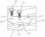
图中:1-底盘本体;2-旋转盘;3-固定座;4-连接杆;5-支撑杆;21-第一螺孔;22-第二螺孔;41-安装导向槽;42-第一连接孔;51-杆头;52-杆叶;53-第一旋紧螺栓;54-第二旋紧螺栓;511-第一定位孔;512-第二定位孔;521-第二连接孔;522-接触面。In the figure: 1- chassis body; 2- rotating disk; 3- fixing seat; 4- connecting rod; 5- supporting rod; 21- first screw hole; 22- second screw hole; 41- installation guide groove; 42- 51-rod head; 52-rod blade; 53-first tightening bolt; 54-second tightening bolt; 511-first positioning hole; 512-second positioning hole; 521-second connection hole; 522 - contact surface.
具体实施方式Detailed ways
现在结合附图对本实用新型作进一步详细的说明。这些附图均为简化的示意图,仅以示意方式说明本实用新型的基本结构,因此其仅显示与本实用新型有关的构成。The present utility model will now be described in further detail in conjunction with the accompanying drawings. These drawings are all simplified schematic diagrams, and only illustrate the basic structure of the present invention in a schematic manner, so they only show the structures related to the present invention.
在本实用新型中,需要说明的是,术语 “上”、“下”、“顶”、“底”等指示的方位或位置关系为基于附图所示的方位或位置关系,仅是为了便于描述本实用新型和简化描述,而不是指示或暗示所指的装置或元件必须具有特定的方位、以特定的方位构造和操作,因此不能理解为对本实用新型的限制;术语“第一”、“第二”仅用于描述目的,而不能理解为指示或暗示相对重要性;此外,除非另有明确的规定和限定,术语“安装”、“相连”、“连接”应做广义理解,例如,可以是固定连接,也可以是可拆卸连接,或一体地连接;可以是机械连接,也可以是电连接;可以是直接相连,也可以通过中间媒介间接相连,可以是两个元件内部的连通。对于本领域的普通技术人员而言,可以具体情况理解上述术语在本实用新型中的具体含义。In the present utility model, it should be noted that the orientation or positional relationship indicated by the terms "upper", "lower", "top", "bottom", etc. is based on the orientation or positional relationship shown in the accompanying drawings, and is only for convenience Describing the present invention and simplifying the description, rather than indicating or implying that the referred device or element must have a specific orientation, be constructed and operated in a specific orientation, and therefore cannot be construed as a limitation to the present invention; the terms "first", "" "Second" is for descriptive purposes only, and should not be construed as indicating or implying relative importance; in addition, unless otherwise expressly specified and limited, the terms "installed", "connected" and "connected" should be construed broadly, for example, It can be a fixed connection, a detachable connection, or an integral connection; a mechanical connection or an electrical connection; a direct connection, an indirect connection through an intermediate medium, or an internal communication between two components. For those of ordinary skill in the art, the specific meanings of the above terms in the present invention can be understood in specific situations.
实施例1Example 1
如图1~3所示,本实用新型提供一种工业大风扇底盘结构,其由底盘本体1、旋转盘2、固定座3、连接杆4和支撑杆5构成,其具有安装方便,结构坚固,安全系数高,风扇风量大等优点,该底盘结构适用范围广,能够满足大部分厂房的需求,其中,所述旋转盘2安装于底盘本体1的上端面;所述固定座3固定于旋转盘2的上端中部;所述连接杆4嵌接固定于固定座3的中部;所述旋转盘2上围绕固定座3设有第一螺孔21和第二螺孔22;所述第二螺孔22设置于旋转盘2的边缘处;所述支撑杆5和旋转盘2通过第一螺孔21和第二螺孔22螺纹连接。As shown in Figures 1 to 3, the present utility model provides an industrial large fan chassis structure, which is composed of a
在本实施例中,所述支撑杆5包括杆头51和杆叶52;所述杆头51为扇形结构;所述杆头51的弧面长端与杆叶52一体连接;所述杆头1的弧面短端与固定座3的侧面相互配合,杆头1与固定座3相互配合,有效较少震动杆叶52的震动程度,使得杆叶52的运动更加平稳,从而提高风扇的安全系数;所述杆头51和杆叶52的连接处沿斜线向下弯折形成接触面522,加大了风扇扇叶安装角度,进而加大了风扇风量;所述杆头51上分别设有第一定位孔511和第二定位孔512;所述第一定位孔511置于杆头1的弧面短端,便于支撑杆5的定位安装,提高底盘的结构强度;所述第一定位孔511上设有第二旋紧螺栓54;所述第二旋紧螺栓54穿过第一定位孔511与第一螺孔21螺纹连接;所述第二定位孔512上设有第一旋紧螺栓53;所述第一旋紧螺栓53穿过第二定位孔512与第二螺孔22螺纹连接;所述杆叶52上设有两个第二连接孔521,便于风扇扇叶的安装,同时使得风扇扇叶的安装更加稳固,从而提高风扇的安全系数。In this embodiment, the
在本实施例中,所述连接杆4上沿着轴线方向设有安装导向槽41;所述连接杆4的侧面贯穿设有三个第一连接孔42;所述第一连接孔42与安装导向槽41相连通,安装导向槽41便于为吊杆的安装起到参照的作用,使得工人能快速准确地完成固定安装工作,并通过第一连接孔42将连接杆4和吊杆固定连接。In this embodiment, the connecting rod 4 is provided with an
以上显示和描述了本实用新型的基本原理和主要特征和本实用新型的优点 ,对于本领域技术人员而言,显然本实用新型不限于上述示范性实施例的细节,而且在不背离本实用新型的精神或基本特征的情况下,能够以其他的具体形式实现本实用新型。因此,无论从哪一点来看,均应将实施例看作是示范性的,而且是非限制性的,本实用新型的范围由所附权利要求而不是上述说明限定,因此旨在将落在权利要求的等同要件的含义和范围内的所有变化囊括在本实用新型内。不应将权利要求中的任何附图标记视为限制所涉及的权利要求。The basic principles and main features of the present invention and the advantages of the present invention have been shown and described above. For those skilled in the art, it is obvious that the present invention is not limited to the details of the above-mentioned exemplary embodiments, and does not deviate from the present invention. The present invention can be implemented in other specific forms under the condition of the spirit or basic features. Therefore, the embodiments are to be considered in all respects as exemplary and not restrictive, and the scope of the present invention is defined by the appended claims rather than the foregoing description, and it is therefore intended that the All changes within the meaning and range of the required equivalents are embraced within the present invention. Any reference signs in the claims shall not be construed as limiting the involved claim.
此外,应当理解,虽然本说明书按照实施方式加以描述,但并非每个实施方式仅包含一个独立的技术方案,说明书的这种叙述方式仅仅是为清楚起见,本领域技术人员应当将说明书作为一个整体,各实施例中的技术方案也可以经适当组合,形成本领域技术人员可以理解的其他实施方式。In addition, it should be understood that although this specification is described in terms of embodiments, not each embodiment only includes an independent technical solution, and this description in the specification is only for the sake of clarity, and those skilled in the art should take the specification as a whole , the technical solutions in each embodiment can also be appropriately combined to form other implementations that can be understood by those skilled in the art.
Claims (8)
Priority Applications (1)
| Application Number | Priority Date | Filing Date | Title |
|---|---|---|---|
| CN201921966821.5UCN211474497U (en) | 2019-11-14 | 2019-11-14 | Industrial large fan chassis structure |
Applications Claiming Priority (1)
| Application Number | Priority Date | Filing Date | Title |
|---|---|---|---|
| CN201921966821.5UCN211474497U (en) | 2019-11-14 | 2019-11-14 | Industrial large fan chassis structure |
Publications (1)
| Publication Number | Publication Date |
|---|---|
| CN211474497Utrue CN211474497U (en) | 2020-09-11 |
Family
ID=72378902
Family Applications (1)
| Application Number | Title | Priority Date | Filing Date |
|---|---|---|---|
| CN201921966821.5UActiveCN211474497U (en) | 2019-11-14 | 2019-11-14 | Industrial large fan chassis structure |
Country Status (1)
| Country | Link |
|---|---|
| CN (1) | CN211474497U (en) |
- 2019
- 2019-11-14CNCN201921966821.5Upatent/CN211474497U/enactiveActive
Similar Documents
| Publication | Publication Date | Title |
|---|---|---|
| CN209587370U (en) | A kind of height-adjustable load-bearing antidetonation suspension and support | |
| CN211474497U (en) | Industrial large fan chassis structure | |
| CN108123405A (en) | A kind of Novel cable bridge stablizes support hanger | |
| CN205141375U (en) | But angle regulation's lightning rod | |
| CN114810484A (en) | Fan variable-pitch and yaw-drive adjustable assembling device | |
| CN202579030U (en) | Auxiliary starting device for perpendicular shaft wind turbine | |
| CN211116416U (en) | A wind turbine flexible tower spoiler device | |
| CN210798442U (en) | Quick installation device of connecting piece for electric power electricity tower | |
| CN205476484U (en) | Device for connecting it is stupefied with back of body to be used for connecting aluminum alloy template | |
| CN209227769U (en) | A kind of connection structure of steel structure column and steel structure girder | |
| CN201152614Y (en) | Substrate for air conditioner | |
| CN217115469U (en) | Bridge with free turning angle | |
| CN211421901U (en) | Planking supports convenient to dismouting | |
| CN202852165U (en) | Manual adjusting device for air quantity adjusting valve | |
| CN203516342U (en) | Connecting structure for screen frame | |
| CN202903267U (en) | Flowmeter with rotatable meter head | |
| CN208056821U (en) | A kind of the gearing square bar fixed structure and its door handle of adjustable length | |
| CN208844960U (en) | A connection structure for grid reinforcement | |
| CN217362151U (en) | Frame fast assembly structure | |
| CN222924758U (en) | Bolt assembly, mounting bracket and air conditioner | |
| CN208185604U (en) | A kind of novel earthquake-proof channel steel base | |
| CN206815536U (en) | A kind of adjustable hanging node of assembled | |
| CN217274558U (en) | Air conditioner bearing pendant | |
| CN204387432U (en) | A kind of break valve for air conditioner and mounting plate thereof | |
| CN217999150U (en) | An adjustable and installed power tower base |
Legal Events
| Date | Code | Title | Description |
|---|---|---|---|
| GR01 | Patent grant | ||
| GR01 | Patent grant |