CN211433450U - Transillumination adapter sleeve device and transillumination adapter - Google Patents
Transillumination adapter sleeve device and transillumination adapterDownload PDFInfo
- Publication number
- CN211433450U CN211433450UCN201920888603.8UCN201920888603UCN211433450UCN 211433450 UCN211433450 UCN 211433450UCN 201920888603 UCN201920888603 UCN 201920888603UCN 211433450 UCN211433450 UCN 211433450U
- Authority
- CN
- China
- Prior art keywords
- light
- wing
- transillumination
- images
- teeth
- Prior art date
- Legal status (The legal status is an assumption and is not a legal conclusion. Google has not performed a legal analysis and makes no representation as to the accuracy of the status listed.)
- Active
Links
Images


Classifications
- H—ELECTRICITY
- H04—ELECTRIC COMMUNICATION TECHNIQUE
- H04N—PICTORIAL COMMUNICATION, e.g. TELEVISION
- H04N13/00—Stereoscopic video systems; Multi-view video systems; Details thereof
- H04N13/20—Image signal generators
- H04N13/204—Image signal generators using stereoscopic image cameras
- H04N13/207—Image signal generators using stereoscopic image cameras using a single 2D image sensor
- H04N13/221—Image signal generators using stereoscopic image cameras using a single 2D image sensor using the relative movement between cameras and objects
- G—PHYSICS
- G06—COMPUTING OR CALCULATING; COUNTING
- G06F—ELECTRIC DIGITAL DATA PROCESSING
- G06F16/00—Information retrieval; Database structures therefor; File system structures therefor
- G06F16/90—Details of database functions independent of the retrieved data types
- G06F16/95—Retrieval from the web
- G06F16/953—Querying, e.g. by the use of web search engines
- G06F16/9535—Search customisation based on user profiles and personalisation
- A—HUMAN NECESSITIES
- A61—MEDICAL OR VETERINARY SCIENCE; HYGIENE
- A61C—DENTISTRY; APPARATUS OR METHODS FOR ORAL OR DENTAL HYGIENE
- A61C19/00—Dental auxiliary appliances
- A61C19/04—Measuring instruments specially adapted for dentistry
- A—HUMAN NECESSITIES
- A61—MEDICAL OR VETERINARY SCIENCE; HYGIENE
- A61B—DIAGNOSIS; SURGERY; IDENTIFICATION
- A61B1/00—Instruments for performing medical examinations of the interior of cavities or tubes of the body by visual or photographical inspection, e.g. endoscopes; Illuminating arrangements therefor
- A61B1/24—Instruments for performing medical examinations of the interior of cavities or tubes of the body by visual or photographical inspection, e.g. endoscopes; Illuminating arrangements therefor for the mouth, i.e. stomatoscopes, e.g. with tongue depressors; Instruments for opening or keeping open the mouth
- A—HUMAN NECESSITIES
- A61—MEDICAL OR VETERINARY SCIENCE; HYGIENE
- A61B—DIAGNOSIS; SURGERY; IDENTIFICATION
- A61B5/00—Measuring for diagnostic purposes; Identification of persons
- A61B5/0059—Measuring for diagnostic purposes; Identification of persons using light, e.g. diagnosis by transillumination, diascopy, fluorescence
- A61B5/0062—Arrangements for scanning
- A—HUMAN NECESSITIES
- A61—MEDICAL OR VETERINARY SCIENCE; HYGIENE
- A61B—DIAGNOSIS; SURGERY; IDENTIFICATION
- A61B5/00—Measuring for diagnostic purposes; Identification of persons
- A61B5/0059—Measuring for diagnostic purposes; Identification of persons using light, e.g. diagnosis by transillumination, diascopy, fluorescence
- A61B5/0082—Measuring for diagnostic purposes; Identification of persons using light, e.g. diagnosis by transillumination, diascopy, fluorescence adapted for particular medical purposes
- A61B5/0084—Measuring for diagnostic purposes; Identification of persons using light, e.g. diagnosis by transillumination, diascopy, fluorescence adapted for particular medical purposes for introduction into the body, e.g. by catheters
- A61B5/0086—Measuring for diagnostic purposes; Identification of persons using light, e.g. diagnosis by transillumination, diascopy, fluorescence adapted for particular medical purposes for introduction into the body, e.g. by catheters using infrared radiation
- A—HUMAN NECESSITIES
- A61—MEDICAL OR VETERINARY SCIENCE; HYGIENE
- A61B—DIAGNOSIS; SURGERY; IDENTIFICATION
- A61B5/00—Measuring for diagnostic purposes; Identification of persons
- A61B5/0059—Measuring for diagnostic purposes; Identification of persons using light, e.g. diagnosis by transillumination, diascopy, fluorescence
- A61B5/0082—Measuring for diagnostic purposes; Identification of persons using light, e.g. diagnosis by transillumination, diascopy, fluorescence adapted for particular medical purposes
- A61B5/0088—Measuring for diagnostic purposes; Identification of persons using light, e.g. diagnosis by transillumination, diascopy, fluorescence adapted for particular medical purposes for oral or dental tissue
- A—HUMAN NECESSITIES
- A61—MEDICAL OR VETERINARY SCIENCE; HYGIENE
- A61B—DIAGNOSIS; SURGERY; IDENTIFICATION
- A61B5/00—Measuring for diagnostic purposes; Identification of persons
- A61B5/45—For evaluating or diagnosing the musculoskeletal system or teeth
- A61B5/4538—Evaluating a particular part of the muscoloskeletal system or a particular medical condition
- A61B5/4542—Evaluating the mouth, e.g. the jaw
- A61B5/4547—Evaluating teeth
- A—HUMAN NECESSITIES
- A61—MEDICAL OR VETERINARY SCIENCE; HYGIENE
- A61B—DIAGNOSIS; SURGERY; IDENTIFICATION
- A61B5/00—Measuring for diagnostic purposes; Identification of persons
- A61B5/72—Signal processing specially adapted for physiological signals or for diagnostic purposes
- A61B5/7203—Signal processing specially adapted for physiological signals or for diagnostic purposes for noise prevention, reduction or removal
- A—HUMAN NECESSITIES
- A61—MEDICAL OR VETERINARY SCIENCE; HYGIENE
- A61B—DIAGNOSIS; SURGERY; IDENTIFICATION
- A61B5/00—Measuring for diagnostic purposes; Identification of persons
- A61B5/74—Details of notification to user or communication with user or patient; User input means
- A61B5/742—Details of notification to user or communication with user or patient; User input means using visual displays
- A61B5/7435—Displaying user selection data, e.g. icons in a graphical user interface
- A—HUMAN NECESSITIES
- A61—MEDICAL OR VETERINARY SCIENCE; HYGIENE
- A61C—DENTISTRY; APPARATUS OR METHODS FOR ORAL OR DENTAL HYGIENE
- A61C1/00—Dental machines for boring or cutting ; General features of dental machines or apparatus, e.g. hand-piece design
- A61C1/08—Machine parts specially adapted for dentistry
- A61C1/088—Illuminating devices or attachments
- A—HUMAN NECESSITIES
- A61—MEDICAL OR VETERINARY SCIENCE; HYGIENE
- A61C—DENTISTRY; APPARATUS OR METHODS FOR ORAL OR DENTAL HYGIENE
- A61C9/00—Impression cups, i.e. impression trays; Impression methods
- A61C9/004—Means or methods for taking digitized impressions
- A61C9/0046—Data acquisition means or methods
- A61C9/0053—Optical means or methods, e.g. scanning the teeth by a laser or light beam
- G—PHYSICS
- G06—COMPUTING OR CALCULATING; COUNTING
- G06Q—INFORMATION AND COMMUNICATION TECHNOLOGY [ICT] SPECIALLY ADAPTED FOR ADMINISTRATIVE, COMMERCIAL, FINANCIAL, MANAGERIAL OR SUPERVISORY PURPOSES; SYSTEMS OR METHODS SPECIALLY ADAPTED FOR ADMINISTRATIVE, COMMERCIAL, FINANCIAL, MANAGERIAL OR SUPERVISORY PURPOSES, NOT OTHERWISE PROVIDED FOR
- G06Q50/00—Information and communication technology [ICT] specially adapted for implementation of business processes of specific business sectors, e.g. utilities or tourism
- G06Q50/01—Social networking
- G—PHYSICS
- G06—COMPUTING OR CALCULATING; COUNTING
- G06T—IMAGE DATA PROCESSING OR GENERATION, IN GENERAL
- G06T15/00—3D [Three Dimensional] image rendering
- G06T15/08—Volume rendering
- G—PHYSICS
- G06—COMPUTING OR CALCULATING; COUNTING
- G06T—IMAGE DATA PROCESSING OR GENERATION, IN GENERAL
- G06T17/00—Three dimensional [3D] modelling, e.g. data description of 3D objects
- G—PHYSICS
- G06—COMPUTING OR CALCULATING; COUNTING
- G06T—IMAGE DATA PROCESSING OR GENERATION, IN GENERAL
- G06T7/00—Image analysis
- G06T7/50—Depth or shape recovery
- G06T7/55—Depth or shape recovery from multiple images
- G—PHYSICS
- G06—COMPUTING OR CALCULATING; COUNTING
- G06T—IMAGE DATA PROCESSING OR GENERATION, IN GENERAL
- G06T7/00—Image analysis
- G06T7/70—Determining position or orientation of objects or cameras
- G06T7/73—Determining position or orientation of objects or cameras using feature-based methods
- G06T7/75—Determining position or orientation of objects or cameras using feature-based methods involving models
- H—ELECTRICITY
- H04—ELECTRIC COMMUNICATION TECHNIQUE
- H04N—PICTORIAL COMMUNICATION, e.g. TELEVISION
- H04N13/00—Stereoscopic video systems; Multi-view video systems; Details thereof
- H04N13/20—Image signal generators
- H04N13/204—Image signal generators using stereoscopic image cameras
- H04N13/246—Calibration of cameras
- H—ELECTRICITY
- H04—ELECTRIC COMMUNICATION TECHNIQUE
- H04N—PICTORIAL COMMUNICATION, e.g. TELEVISION
- H04N13/00—Stereoscopic video systems; Multi-view video systems; Details thereof
- H04N13/20—Image signal generators
- H04N13/204—Image signal generators using stereoscopic image cameras
- H04N13/254—Image signal generators using stereoscopic image cameras in combination with electromagnetic radiation sources for illuminating objects
- H—ELECTRICITY
- H04—ELECTRIC COMMUNICATION TECHNIQUE
- H04N—PICTORIAL COMMUNICATION, e.g. TELEVISION
- H04N13/00—Stereoscopic video systems; Multi-view video systems; Details thereof
- H04N13/20—Image signal generators
- H04N13/257—Colour aspects
- H—ELECTRICITY
- H04—ELECTRIC COMMUNICATION TECHNIQUE
- H04N—PICTORIAL COMMUNICATION, e.g. TELEVISION
- H04N13/00—Stereoscopic video systems; Multi-view video systems; Details thereof
- H04N13/20—Image signal generators
- H04N13/271—Image signal generators wherein the generated image signals comprise depth maps or disparity maps
- A—HUMAN NECESSITIES
- A61—MEDICAL OR VETERINARY SCIENCE; HYGIENE
- A61B—DIAGNOSIS; SURGERY; IDENTIFICATION
- A61B2560/00—Constructional details of operational features of apparatus; Accessories for medical measuring apparatus
- A61B2560/02—Operational features
- A61B2560/0223—Operational features of calibration, e.g. protocols for calibrating sensors
- G—PHYSICS
- G06—COMPUTING OR CALCULATING; COUNTING
- G06T—IMAGE DATA PROCESSING OR GENERATION, IN GENERAL
- G06T2207/00—Indexing scheme for image analysis or image enhancement
- G06T2207/30—Subject of image; Context of image processing
- G06T2207/30004—Biomedical image processing
- G06T2207/30036—Dental; Teeth
- G—PHYSICS
- G06—COMPUTING OR CALCULATING; COUNTING
- G06T—IMAGE DATA PROCESSING OR GENERATION, IN GENERAL
- G06T2207/00—Indexing scheme for image analysis or image enhancement
- G06T2207/30—Subject of image; Context of image processing
- G06T2207/30244—Camera pose
- G—PHYSICS
- G06—COMPUTING OR CALCULATING; COUNTING
- G06T—IMAGE DATA PROCESSING OR GENERATION, IN GENERAL
- G06T2210/00—Indexing scheme for image generation or computer graphics
- G06T2210/41—Medical
Landscapes
- Health & Medical Sciences (AREA)
- Life Sciences & Earth Sciences (AREA)
- Engineering & Computer Science (AREA)
- Physics & Mathematics (AREA)
- General Health & Medical Sciences (AREA)
- Public Health (AREA)
- Animal Behavior & Ethology (AREA)
- Veterinary Medicine (AREA)
- Surgery (AREA)
- Biophysics (AREA)
- Biomedical Technology (AREA)
- Pathology (AREA)
- Heart & Thoracic Surgery (AREA)
- Medical Informatics (AREA)
- Molecular Biology (AREA)
- Oral & Maxillofacial Surgery (AREA)
- Theoretical Computer Science (AREA)
- Dentistry (AREA)
- General Physics & Mathematics (AREA)
- Signal Processing (AREA)
- Multimedia (AREA)
- Epidemiology (AREA)
- Computer Vision & Pattern Recognition (AREA)
- Radiology & Medical Imaging (AREA)
- Nuclear Medicine, Radiotherapy & Molecular Imaging (AREA)
- Computer Graphics (AREA)
- Optics & Photonics (AREA)
- Audiology, Speech & Language Pathology (AREA)
- Business, Economics & Management (AREA)
- Databases & Information Systems (AREA)
- Geometry (AREA)
- Software Systems (AREA)
- Electromagnetism (AREA)
- Human Resources & Organizations (AREA)
- General Business, Economics & Management (AREA)
- Computing Systems (AREA)
- Economics (AREA)
- Tourism & Hospitality (AREA)
- Marketing (AREA)
- Primary Health Care (AREA)
Abstract
Description
Translated fromChinese本申请是申请日为2017年7月27日,申请号为201720922787.6,实用新型名称为“具有牙科诊断能力的口内扫描仪(变更后的名称为“口内扫描系统和口内扫描装置”)”的申请的分案申请。The application date is July 27, 2017, the application number is 201720922787.6, and the utility model name is "Intraoral Scanner with Dental Diagnostic Capability (the changed name is "Intraoral Scanning System and Intraoral Scanning Device")" divisional application.
相关申请的交叉引用CROSS-REFERENCE TO RELATED APPLICATIONS
本专利申请要求以下各项的优先权:2016年7月27日提交的且标题为“INTRAORALSCANNER WITH DENTAL DIAGNOSTICS CAPABILITIES”的美国临时专利申请第62/367,607号;2017年3月27日提交的且标题为“INTRAORAL SCANNER WITH DENTAL DIAGNOSTICSCAPABILITIES”的美国临时专利申请第62/477,387号;和 2017年6月9日提交的且标题为“MINIMAL VALUE LIFTING TO FORM A VOLUMETRIC MODEL OF AN OBJECT”的美国临时专利申请第 62/517,467号。这些专利申请中的每一个通过引用以其整体并入本文。This patent application claims priority to: US Provisional Patent Application No. 62/367,607, filed July 27, 2016 and entitled "INTRAORALSCANNER WITH DENTAL DIAGNOSTICS CAPABILITIES"; filed March 27, 2017 and entitled U.S. Provisional Patent Application No. 62/477,387 for "INTRAORAL SCANNER WITH DENTAL DIAGNOSTICSCAPABILITIES"; and U.S. Provisional Patent Application No. 62/477,387 for "INTRAORAL SCANNER WITH DENTAL DIAGNOSTICSCAPABILITIES"; 62/517,467. Each of these patent applications is incorporated herein by reference in its entirety.
通过引用并入incorporated by reference
本说明书中提及的所有公开和专利申请均通过引用以其整体并入本文,其程度如同每个单独的公开或专利申请被明确地和单独地指出以通过引用并入。All publications and patent applications mentioned in this specification are herein incorporated by reference in their entirety to the same extent as if each individual publication or patent application was specifically and individually indicated to be incorporated by reference.
技术领域technical field
本文描述的方法和装置可以涉及光学扫描仪,且特别是用于生成对象的三维表示。特别地,本文描述了可用于包括3D扫描的扫描和对口腔分析以用于诊断、治疗、纵向跟踪、牙齿测量以及龋齿和裂纹的检测的方法和装置。这些方法和装置可生成体积模型,和/或可包括彩色扫描。The methods and apparatus described herein may relate to optical scanners, and in particular for generating three-dimensional representations of objects. In particular, described herein are methods and apparatus that can be used for scanning, including 3D scanning, and analysis of the oral cavity for diagnosis, treatment, longitudinal tracking, tooth measurement, and detection of caries and cracks. These methods and apparatus may generate volumetric models, and/or may include color scans.
背景技术Background technique
许多牙科和正畸手术可以得益于对患者齿状和口腔的精确三维(3D) 描述。特别地,提供包括牙釉质和牙本质及龋齿的牙齿的表面和内部结构的三维描述以及牙齿体积的一般内部组成将是有帮助的。虽然牙齿3D表面的纯表面表示已被证明在牙科假体(例如,牙冠或牙桥)的设计和制造以及治疗计划中非常有用,但是对内部结构(包括牙釉质和下面牙本质中的龋齿和裂纹的生长)进行成像的能力将非常有用,特别是与表面形貌绘图相结合。Many dental and orthodontic procedures can benefit from an accurate three-dimensional (3D) depiction of a patient's dentition and mouth. In particular, it would be helpful to provide a three-dimensional description of the surface and internal structure of a tooth including enamel and dentin and caries, as well as the general internal composition of the tooth volume. While pure surface representations of 3D surfaces of teeth have proven to be very useful in the design and manufacture of dental prostheses (eg, crowns or bridges) and in treatment planning, it is difficult to understand caries in internal structures, including enamel and underlying dentin. and crack growth) would be very useful, especially in combination with surface topography mapping.
历史上,已经使用电离辐射(例如,X射线)来对牙齿成像。例如, X射线咬翼片照相通常用于向牙齿提供非定量图像。然而,除了电离辐射的风险之外,这样的图像通常在其显示特征的能力方面受到限制并且可能涉及漫长且昂贵的程序。诸如锥束计算断层摄影术的其他技术可提供层析图像,但仍需要电离辐射。Historically, teeth have been imaged using ionizing radiation (eg, X-rays). For example, X-ray bitewing radiography is often used to provide non-quantitative images of teeth. However, in addition to the risk of ionizing radiation, such images are often limited in their ability to reveal features and can involve lengthy and expensive procedures. Other techniques, such as cone beam computed tomography, provide tomographic images, but still require ionizing radiation.
因此,提供可以用于对受试者的牙齿或多个牙齿建模并且包括外部 (表面)和内部(在牙釉质和牙本质内)结构和组成的、包括诸如口内扫描系统的设备和系统的方法和装置将是有益的。特别地,提供可以使用单个装置来提供该能力的方法和装置将是有帮助的。存在对于改进的方法和系统来用于扫描患者口腔和/或用于使牙龋齿(dental carries)的识别和分析自动化的需要。Accordingly, there are provided devices and systems, including such as intraoral scanning systems, that can be used to model a subject's tooth or teeth and include both external (surface) and internal (within enamel and dentin) structure and composition. Methods and apparatus would be beneficial. In particular, it would be helpful to provide methods and apparatus that can use a single apparatus to provide this capability. There is a need for improved methods and systems for scanning a patient's mouth and/or for automating the identification and analysis of dental carries.
实用新型内容Utility model content
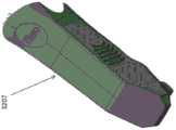
通常,本文描述了用于扫描牙齿的外部和/或内部结构的方法和装置 (例如,设备和系统)。这些方法和装置可以生成包括表面形貌和内部特征(例如,牙本质、牙填充体、裂纹和/或龋齿)的受试者牙齿的模型。这些装置中的任何一个可以包括用于扫描受试者的口腔中或周围的口内扫描仪,并且其配备有可以在以下两个或更多个光谱范围中照射的一个光源或多个光源:表面特征照射光谱范围(例如,可见光)和穿透光谱范围(例如,IR范围且特别是“近IR”,包括但不限于850nm)。扫描装置还可以包括用于检测发射光的一个或更多个传感器和一个或更多个处理器,该一个或更多个处理器用于控制扫描操作并且用于分析来自第一光谱范围和第二光谱范围的接收光,以生成包括牙齿表面和牙齿内(包括在牙釉质和牙本质内)的特征的受试者的牙齿的模型。Generally, methods and apparatus (eg, devices and systems) for scanning the external and/or internal structures of teeth are described herein. These methods and apparatus can generate a model of a subject's teeth including surface topography and internal features (eg, dentin, dental fillings, cracks, and/or caries). Any of these devices may include an intraoral scanner for scanning in or around a subject's oral cavity, and which is equipped with a light source or light sources that can illuminate in two or more of the following spectral ranges: Surface Characteristic illumination spectral range (eg, visible light) and transmission spectral range (eg, IR range and particularly "near IR", including but not limited to 850 nm). The scanning device may also include one or more sensors for detecting the emitted light and one or more processors for controlling the scanning operation and for analyzing light from the first spectral range and the second A spectral range of light is received to generate a model of the subject's teeth including features on the tooth surface and within the tooth, including within the enamel and dentin.
本文描述的方法通常包括用于生成受试者牙齿的模型的方法,其通常生成包括表面和内部特征的牙齿的三维模型或渲染。可以使用成像和/或检测内部结构的非电离方法,诸如使用穿透波长拍摄图像以通过使用一个或更多个穿透光谱范围(波长)来照射它们而观察牙齿内的结构,包括使用透照法(trans-illumination)(例如,从一侧照射和在穿过对象之后从相对侧捕获光)、和/或小角度穿透成像(例如,反射成像,当以穿透波长照射时捕获从内部结构反射/散射的光)。特别地,可以从相同的相对位置拍摄多个穿透图像。尽管可以使用传统的穿透成像技术(例如,透照法),其中光发射器照射方向和检测器(例如,相机)视角之间的角度为90度或 180度,但是本文还描述了其中角度小得多(例如,0度与25度之间、0 度与20度之间、0度至15度之间、0度至10度之间等等)的方法和装置。较小的角度(例如,0-15°)可能是特别有利的,因为照射(光源)和感测 (检测器(detector(s)),例如相机(camera(s))等)可以彼此更靠近,并且可以提供可以更容易地在受试者的牙齿周围定位和移动的用于口内扫描仪的扫描棒。这些小角度穿透图像和成像技术在本文中也可以称为反射照射和/或成像,或者为反射/散射成像。一般来说,穿透成像可以指任何适当类型的穿透成像,除非另有说明,包括透照法、小角度穿透成像等。The methods described herein generally include methods for generating a model of a subject's teeth, typically generating a three-dimensional model or rendering of the teeth including surface and internal features. Non-ionizing methods of imaging and/or detecting internal structures may be used, such as taking images using transmissive wavelengths to view structures within the tooth by illuminating them using one or more transmissive spectral ranges (wavelengths), including the use of transillumination trans-illumination (e.g., illuminating from one side and capturing light from the opposite side after passing through the object), and/or low-angle transillumination (e.g., reflection imaging, capturing light from inside when illuminated at a transmissive wavelength) Structure reflected/scattered light). In particular, multiple penetration images can be taken from the same relative position. Although conventional penetration imaging techniques (eg, transillumination) can be used, where the angle between the direction of illumination of the light emitter and the viewing angle of the detector (eg, camera) is 90 or 180 degrees, the document also describes where the angle Much smaller (eg, between 0 and 25 degrees, between 0 and 20 degrees, between 0 and 15 degrees, between 0 and 10 degrees, etc.) methods and apparatus. Smaller angles (eg, 0-15°) may be particularly advantageous since illumination (light source) and sensing (detector(s), eg camera(s), etc.) can be brought closer to each other , and can provide a wand for an intraoral scanner that can be more easily positioned and moved around a subject's teeth. These low angle penetration imaging and imaging techniques may also be referred to herein as reflected illumination and/or imaging, or as reflection/scatter imaging. In general, penetrating imaging may refer to any suitable type of penetrating imaging, including transillumination, low-angle penetrating imaging, and the like, unless otherwise specified.
本文描述的方法和装置特别有效地将一个牙齿或多个牙齿的3D表面模型与诸如损伤(龋齿,裂纹等)的成像的内部特征组合,该内部特征可以通过对由使用口内扫描仪来进行穿透成像的使用来检测,该口内扫描仪适用于表面和内部特征的分开但同时(或几乎同时)的检测。将表面扫描和穿透成像组合可以通过以允许对两者使用相同坐标系的方式在这些不同模态之间交替或切换来执行。可选地,表面和穿透扫描二者可以例如通过选择性地对成像的波长滤波以分离IR(近IR)光与可见光而同时进行观看。因此,3D表面数据可提供关于内部结构的重要参考和角度信息,并且可以允许对原本可能难以解释或不可解释的透照图像进行解释和分析。The methods and devices described herein are particularly effective in combining a 3D surface model of a tooth or teeth with imaged internal features such as lesions (caries, cracks, etc.) that can be punctured by using an intraoral scanner The use of through-imaging to detect, the intraoral scanner is suitable for separate but simultaneous (or nearly simultaneous) inspection of surface and internal features. Combining surface scanning and penetration imaging can be performed by alternating or switching between these different modalities in a manner that allows the use of the same coordinate system for both. Alternatively, both surface and penetration scans can be viewed simultaneously, eg, by selectively filtering the imaged wavelengths to separate IR (near IR) light from visible light. Thus, 3D surface data can provide important reference and angular information about internal structures, and can allow interpretation and analysis of transillumination images that might otherwise be difficult or uninterpretable.
例如,本文描述了用于生成受试者牙齿的模型的方法,包括以下步骤:使用口内扫描仪捕获受试者的牙齿的至少一部分的三维(3D)表面模型数据;利用口内扫描仪使用穿透波长对牙齿拍摄多个图像;以及使用3D表面模型数据和多个图像来形成包括内部结构的牙齿的3D模型。For example, described herein is a method for generating a model of a subject's teeth, comprising the steps of: capturing three-dimensional (3D) surface model data of at least a portion of the subject's teeth using an intraoral scanner; using penetrating using the intraoral scanner The wavelength takes a plurality of images of the tooth; and the 3D surface model data and the plurality of images are used to form a 3D model of the tooth including the internal structure.
用于生成受试者的牙齿的模型的方法可以包括:用在第一成像模态下操作的口内扫描仪捕获受试者的牙齿的至少一部分的三维(3D)表面模型数据,其中3D表面模型数据具有第一坐标系;使用穿透波长以第二成像模态操作的口内扫描仪对牙齿拍摄多个图像,其中所述多个图像参考第一坐标系;以及使用3D表面模型数据和所述多个图像来形成包括内部结构的牙齿的3D模型。A method for generating a model of a subject's teeth may include capturing three-dimensional (3D) surface model data of at least a portion of a subject's teeth with an intraoral scanner operating in a first imaging modality, wherein the 3D surface model the data has a first coordinate system; taking a plurality of images of the tooth using an intraoral scanner operating in a second imaging modality using a penetration wavelength, wherein the plurality of images are referenced to the first coordinate system; and using the 3D surface model data and the Multiple images to form a 3D model of the tooth including the internal structure.
通常,捕获3D表面模型数据可以包括使用任何适当的方法来确定3D 表面拓扑。例如,确定3D表面拓扑可以包括使用共焦聚焦。捕获3D表面模型数据可以包括使用以下中的一种或更多种:共焦扫描、立体视觉或结构光三角测量。In general, capturing 3D surface model data may include using any suitable method to determine 3D surface topology. For example, determining 3D surface topology can include using confocal focusing. Capturing 3D surface model data may include using one or more of the following: confocal scanning, stereo vision, or structured light triangulation.
本文描述的方法和装置中的任一个可以用于对单个牙齿或牙齿的区域、多个牙齿、牙齿和牙龈或其它口内结构(特别是在受试者的口部内) 进行建模、成像和/或渲染3D图像。Any of the methods and devices described herein may be used to model, image and/or model a single tooth or region of teeth, multiple teeth, teeth and gums, or other intraoral structures (particularly within a subject's mouth). Or render 3D images.
通常,本文所述的方法及用于执行它们的装置包括3D彩色口内扫描/ 扫描仪。例如,该方法可以包括捕获彩色口内3D数据。Generally, the methods described herein and devices for performing them include 3D color intraoral scanning/scanners. For example, the method may include capturing color intraoral 3D data.
如将在下面更详细地描述的,该方法和装置可以控制在收集表面数据和收集穿透成像(穿透)数据之间的切换。例如,这些方法中任意一个方法可包括例如通过在第一成像模态和第二(穿透)成像模式之间切换来在 3D表面模型数据被捕获时使用穿透波长拍摄图像。As will be described in more detail below, the method and apparatus can control switching between collecting surface data and collecting penetration imaging (penetration) data. For example, any of these methods may include taking an image using the transmission wavelength when the 3D surface model data is captured, such as by switching between a first imaging modality and a second (transmission) imaging mode.
可以使用相同的传感器或不同的传感器来收集表面和内部特征数据。例如,拍摄多个图像可以包括在口内扫描器上使用相同的传感器来捕获3D 表面模型数据和使用穿透波长捕获多个图像。可选地,可以使用单独的传感器或多个传感器。例如,拍摄多个图像可以包括在口内扫描器上使用不同的传感器来捕获3D表面模型数据和使用穿透波长捕获多个图像。The same sensor or different sensors can be used to collect surface and interior feature data. For example, capturing multiple images may include using the same sensor on the intraoral scanner to capture 3D surface model data and capturing multiple images using the transmission wavelength. Alternatively, a single sensor or multiple sensors may be used. For example, capturing multiple images may include using different sensors on the intraoral scanner to capture 3D surface model data and capturing multiple images using transmission wavelengths.
如上所述,使用穿透波长(或穿透光谱范围)拍摄牙齿的图像可以包括以照射源和传感器(例如,检测器或相机)之间的任何角度拍摄穿透图像。特别地,可以使用小角度配置对内部特征(例如,反射成像)数据进行成像,其中以相对于牙齿/多颗牙齿的不同取向拍摄一个或优选地更多个穿透图像。例如,拍摄多个图像可以包括相对于接收来自牙齿的照射的传感器(例如,检测器、相机等)以0°和15°之间的角度照射牙齿,反射牙齿/多颗牙齿的内部组成。拍摄多个图像(例如,穿透图像,诸如这些小角度穿透图像)通常包括在口内扫描仪相对于牙齿的不同角度处在牙齿的相同区域处拍摄一个或更多个(例如,多个,包括两个或更多个,三个或更多个等)穿透图像。这样,牙齿的相同的内部区域将出现在来自不同角度的多个不同扫描中。As described above, capturing images of teeth using the penetration wavelength (or penetration spectral range) may include capturing penetration images at any angle between the illumination source and the sensor (eg, detector or camera). In particular, internal feature (eg, reflection imaging) data may be imaged using a small angle configuration, wherein one or preferably more penetration images are taken at different orientations relative to the tooth/teeth. For example, taking multiple images may include illuminating the tooth at an angle between 0° and 15° relative to a sensor (eg, detector, camera, etc.) that receives illumination from the tooth, reflecting the internal composition of the tooth/teeth. Taking multiple images (eg, penetrating images, such as these small-angle penetrating images) typically involves taking one or more (eg, multiple, including two or more, three or more, etc.) penetrating images. In this way, the same interior area of the tooth will appear in multiple different scans from different angles.
通常,任意数量的传感器可被包括在口内扫描仪上,例如在口内扫描器的棒上。可以使用用于检测和记录(例如,光的)适当的光谱范围的任何适当的传感器。传感器可以涉及并且可以包括检测器、相机等。例如,拍摄多个图像可以包括在口内扫描器上使用多个传感器以使用穿透波长捕获多个图像。Generally, any number of sensors can be included on the intraoral scanner, such as on the wand of the intraoral scanner. Any suitable sensor for detecting and recording the appropriate spectral range (eg, of light) may be used. Sensors may involve and may include detectors, cameras, and the like. For example, capturing multiple images may include using multiple sensors on the intraoral scanner to capture multiple images using the penetrating wavelength.
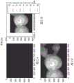
用于拍摄穿透图像的照射通常是穿透的,使得其可以至少部分地穿透并穿过牙齿的牙釉质和牙本质。光的穿透波长通常可以包括红外(且特别是近红外)光。例如,可以使用在700至1090nm范围内(例如,850nm) 的光。可以使用其它波长和波长范围,包括比可见光谱短的波长。因此,拍摄多个图像可以包括用红外光照射牙齿。拍摄多个图像(例如,穿透图像)可以包括用白光(包括但不限于白光透照)、UV/蓝荧光和红光荧光中的一种或更多种来照射牙齿。The illumination used to take the penetrating image is usually penetrating so that it can at least partially penetrate and pass through the enamel and dentin of the tooth. Transmissive wavelengths of light may generally include infrared (and particularly near-infrared) light. For example, light in the range of 700 to 1090 nm (eg, 850 nm) can be used. Other wavelengths and wavelength ranges can be used, including wavelengths shorter than the visible spectrum. Thus, taking multiple images may include illuminating the tooth with infrared light. Taking multiple images (eg, through images) may include illuminating the tooth with one or more of white light (including but not limited to white light transillumination), UV/blue fluorescence, and red fluorescence.
通常,可以使用任何适当的技术来形成包括来自穿透成像的(组合的) 表面和内部结构的牙齿的3D模型。这些3D模型可以被称为组合的3D表面/体积模型、3D体积表面模型或简单地称为“3D模型”等。如上所述,表面数据和穿透成像数据通常可以在相同的坐标系中。两者可以通过使用公共坐标系进行组合。在一些变型中,表面数据可以表示为表面模型和添加到该模型中的内部特征。在一些变型中,数据可以(在加在一起之后)同时重建成三维模型。一个或两个数据集可以被单独修改(例如,滤波、减法等)。例如,形成包括内部结构的牙齿的3D模型可以包括将3D表面模型数据与内部结构数据(包括体积数据)组合。形成包括内部结构的牙齿的3D模型可以包括组合多个穿透图像,其中可以使用口内扫描仪从多个角度拍摄多个穿透图像。In general, any suitable technique can be used to form the 3D model of the tooth including the (combined) surface and internal structure from the penetration imaging. These 3D models may be referred to as combined 3D surface/volume models, 3D volume surface models, or simply "3D models", or the like. As mentioned above, surface data and penetration imaging data can generally be in the same coordinate system. Both can be combined by using a common coordinate system. In some variations, the surface data may be represented as a surface model and internal features added to the model. In some variations, the data can be simultaneously reconstructed (after being added together) into a three-dimensional model. One or both datasets may be individually modified (eg, filtered, subtracted, etc.). For example, forming a 3D model of a tooth including internal structure may include combining 3D surface model data with internal structure data (including volume data). Forming the 3D model of the tooth including the internal structure may include combining multiple penetration images, wherein the multiple penetration images may be taken from multiple angles using an intraoral scanner.
在本文所述的任何方法中及在被配置为执行这些方法的装置中,数据可以由系统自动或手动地进行分析。特别地,本文描述的方法和装置可以包括检查内部特征和/或识别感兴趣的特征,包括裂纹和龋齿。可以基于特征识别标准(例如,穿透图像中的暗区域或亮区域)、模式识别、机器学习等来识别特征。特征可以被标记,包括着色、标签等。特征可以被直接标记在3D模型中、在穿透图像上、或者在参考在由本文描述的方法和装置形成的牙齿的3D模型(例如,与其共享坐标系)的数据结构中。In any of the methods described herein, and in apparatuses configured to perform these methods, the data may be analyzed by the system automatically or manually. In particular, the methods and devices described herein may include examining internal features and/or identifying features of interest, including cracks and caries. Features may be identified based on feature identification criteria (eg, penetrating dark or light regions in an image), pattern recognition, machine learning, and the like. Features can be marked, including coloring, labels, etc. Features may be marked directly in the 3D model, on the penetration image, or in a data structure that references (eg, shares a coordinate system with) the 3D model of the tooth formed by the methods and apparatus described herein.
本文还描述了被配置为执行所描述的任何方法的装置。例如,本文描述了用于生成受试者的牙齿的模型的口内扫描系统,其包括:具有至少一个传感器和多个光源的手持式棒,其中光源被配置为以第一光谱范围和第二光谱范围发射光,其中第二光谱范围是穿透的;以及可操作地连接到手持式棒的一个或更多个处理器,该一个或更多个处理器被配置为:使用来自第一光谱范围的光生成受试者的牙齿的至少一部分的三维(3D)表面模型;并且基于3D表面模型以及基于以显示内部结构的第二光谱范围拍摄的多个图像生成包括内部结构的受试者的牙齿的3D模型。Also described herein are apparatuses configured to perform any of the methods described. For example, described herein is an intraoral scanning system for generating a model of a subject's teeth, comprising: a hand-held wand having at least one sensor and a plurality of light sources, wherein the light sources are configured in a first spectral range and a second spectral range a range of emitting light, wherein the second spectral range is transmissive; and one or more processors operably connected to the hand-held wand, the one or more processors configured to: use light from the first spectral range generating a three-dimensional (3D) surface model of at least a portion of the subject's teeth; and generating the subject's teeth including the internal structure based on the 3D surface model and based on the plurality of images captured in the second spectral range showing the internal structure 3D model.
用于生成受试者的牙齿的模型的口内扫描系统可以包括:具有至少一个传感器和多个光源的手持式棒,其中光源被配置为以第一光谱范围和第二光谱发射光,而且其中第二光谱范围是穿透的;以及可操作地连接到手持式棒的一个或更多个处理器,该一个或更多个处理器被配置为:使用第一坐标系,通过使用由手持式棒感测到的第一光谱范围中的光来确定表面信息;使用表面信息来生成受试者的牙齿的至少一部分的三维(3D)表面模型;在第二光谱范围中拍摄多个图像,其中图像参考第一坐标系;并且基于3D表面模型和多个图像生成包括内部结构的受试者的牙齿的3D模型。The intraoral scanning system for generating a model of a subject's teeth may include: a hand-held wand having at least one sensor and a plurality of light sources, wherein the light sources are configured to emit light in a first spectral range and a second spectral range, and wherein a third two spectral ranges are penetrating; and one or more processors operably connected to the hand-held wand, the one or more processors configured to: sensing light in the first spectral range to determine surface information; using the surface information to generate a three-dimensional (3D) surface model of at least a portion of the subject's teeth; capturing a plurality of images in the second spectral range, wherein the image referencing a first coordinate system; and generating a 3D model of the subject's teeth including internal structures based on the 3D surface model and the plurality of images.
本文还描述了生成受试者的牙齿的模型的方法,该受试者的牙齿的模型包括表面和内部结构,其中相同的口内扫描仪在不同模态之间循环,诸如在表面扫描和穿透之间循环;也可以可选地包括附加模态(例如,激光荧光等)。通常,虽然本文描述的示例关注于表面和穿透的组合上,但是替代本文描述的内部特征成像或除此之外,可以使用其它内部扫描技术 (例如,激光荧光)。Also described herein are methods of generating a model of a subject's teeth, the model of the subject's teeth including surfaces and internal structures, wherein the same intraoral scanner is cycled between different modalities, such as scanning at the surface and penetrating cycles between; additional modalities (eg, laser fluorescence, etc.) may also optionally be included. In general, although the examples described herein focus on a combination of surface and penetration, other internal scanning techniques (eg, laser fluorescence) may be used instead of or in addition to the imaging of internal features described herein.
例如,本文描述了生成包括表面和内部结构的受试者的牙齿的模型的方法,包括以下步骤:使用手持式口内扫描仪,使用第一模态来扫描受试者的牙齿的一部分以捕获牙齿的三维(3D)表面模型数据;使用手持式口内扫描仪,使用第二模态来扫描受试者的牙齿的该部分,以使用穿透波长对牙齿成像来捕获牙齿的内部数据;在第一模态和第二模态之间循环,其中循环在第一模态和第二模态之间快速切换,使得使用穿透波长的图像与在第一模态中捕获的3D表面模型数据共享坐标系。For example, described herein are methods of generating a model of a subject's teeth including surfaces and internal structures, comprising the steps of: using a hand-held intraoral scanner, scanning a portion of the subject's teeth to capture the teeth using a first modality three-dimensional (3D) surface model data of the subject; using a hand-held intraoral scanner, the portion of the subject's tooth is scanned using a second modality to image the tooth using a penetrating wavelength to capture the internal data of the tooth; in the first Cycling between the modality and the second modality, where the cycle rapidly switches between the first modality and the second modality such that the images using the penetrating wavelengths share coordinates with the 3D surface model data captured in the first modality Tie.
本文描述的任何方法可以包括自动调整在第一模态中进行扫描花费的持续时间、在第二模态中花费的持续时间、或者在第一模态和第二模态之间循环时花费在第一模态和第二模态中的持续时间。例如,这些方法中的任何一种可以包括自动调整在第一模态中进行扫描花费的持续时间、在第二模态中花费的持续时间、或基于所捕获的3D表面模型数据、内部数据或3D表面模型数据和内部数据两者在第一模态和第二模态之间循环时花费在第一模态和第二模态中的持续时间。因此,生成受试者的牙齿的模型的方法可以包括:使用手持式口内扫描仪,使用第一模态扫描受试者的牙齿的一部分以捕获牙齿的三维(3D)表面模型数据;使用手持式口内扫描仪,使用第二模态来扫描受试者的牙齿的该部分,以使用穿透波长对牙齿成像,以捕获牙齿的内部数据;使用扫描方案在第一模态和第二模态之间循环,其中循环在第一模态和第二模态之间快速切换,使得内部数据使用与在第一模态中捕获的3D表面模型数据相同的坐标系;并且基于所捕获的3D表面模型数据、内部数据或3D表面模型数据和内部数据二者来调整扫描方案。Any of the methods described herein may include automatically adjusting the duration spent scanning in the first modality, the duration spent in the second modality, or the duration spent while cycling between the first modality and the second modality Duration in the first modality and the second modality. For example, any of these methods may include automatically adjusting the duration spent scanning in the first modality, the duration spent in the second modality, or based on captured 3D surface model data, internal data or Duration that both the 3D surface model data and the internal data spend in the first modality and the second modality while cycling between the first modality and the second modality. Accordingly, a method of generating a model of a subject's teeth may include: using a handheld intraoral scanner, scanning a portion of the subject's teeth using a first modality to capture three-dimensional (3D) surface model data of the teeth; using a handheld intraoral scanner an intraoral scanner that scans the portion of a subject's teeth using a second modality to image the teeth using penetrating wavelengths to capture internal data of the teeth; using a scanning protocol between the first modality and the second modality an inter-loop in which the loop switches rapidly between the first modality and the second modality such that the internal data uses the same coordinate system as the 3D surface model data captured in the first modality; and is based on the captured 3D surface model data, internal data or both 3D surface model data and internal data to adjust the scanning scheme.
扫描方案调整可以包括基于对所捕获的3D表面模型数据的质量的确定进行调整。调整扫描方案可以包括自动调整扫描方案、和/或调整第一模态中扫描的持续时间和/或调整第二模态中扫描的持续时间。Scanning scheme adjustment may include making adjustments based on a determination of the quality of the captured 3D surface model data. Adjusting the scan schedule may include automatically adjusting the scan schedule, and/or adjusting the duration of the scan in the first modality and/or adjusting the duration of the scan in the second modality.
这些方法中的任一个可以包括组合3D表面模型数据和牙齿的内部数据以形成牙齿的3D模型。Any of these methods may include combining the 3D surface model data and the internal data of the tooth to form a 3D model of the tooth.
如上所述,捕获3D表面模型数据可以包括使用共焦聚焦/共焦扫描、立体视觉或结构光三角测量来确定3D表面拓扑。As described above, capturing 3D surface model data may include determining 3D surface topology using confocal/confocal scanning, stereo vision, or structured light triangulation.
通常,循环可以包括在第一模态、第二模态和第三模态之间的循环,其中循环在第一模态、第二模态和第三模态之间快速切换,使得使用穿透波长的图像与在第一模式中捕获的3D表面模型共享坐标系。第三模态可能是另一种穿透模态或非穿透模态(例如,受试者的牙齿的颜色、视觉图像等)。Typically, cycling may include cycling between the first, second, and third modes, wherein the cycling rapidly switches between the first, second, and third modes, such that the use of wear The wavelength-transparent image shares a coordinate system with the 3D surface model captured in the first mode. The third modality may be another penetrating modality or a non-penetrating modality (eg, the color of the subject's teeth, a visual image, etc.).
使用手持式口内扫描仪来使用第二模态扫描受试者的牙齿的部分可以包括相对于接收照射的传感器的观看方向以0°和15°之间的角度(例如,小角度照射)照射牙齿。使用手持式口内扫描仪来使用第二模态扫描受试者的牙齿的该部分的步骤可以包括以在照射源和传感器之间的多个不同的角度和/或以相对于牙齿的多个不同的位置或角度拍摄多个穿透图像,使得牙齿的相同内部区域从相对于牙齿的不同角度成像。Using the handheld intraoral scanner to scan the portion of the subject's teeth using the second modality may include illuminating the teeth at an angle between 0° and 15° (eg, small angle illumination) relative to the viewing direction of the sensor receiving the illumination . Using the handheld intraoral scanner to scan the portion of the subject's teeth using the second modality may include at multiple different angles between the illumination source and the sensor and/or at multiple different angles relative to the teeth Multiple penetrating images are taken at the location or angle so that the same interior area of the tooth is imaged from different angles relative to the tooth.
如上所述,可以使用任何适当的穿透波长,包括红外线(例如,近红外线)。例如,使用手持式口内扫描仪来使用第二模态扫描受试者的牙齿的部分可以包括用以下中的一种或更多种进行照射:白光透照、UV/蓝荧光和红光荧光。As noted above, any suitable transmission wavelength may be used, including infrared (eg, near infrared). For example, scanning a portion of a subject's teeth using a second modality using a handheld intraoral scanner may include illuminating with one or more of the following: white light transillumination, UV/blue fluorescence, and red fluorescence.
本文还描述了用于生成受试者的牙齿的模型的口内扫描系统,其被配置为在扫描模式之间循环。例如,本文描述了口内扫描系统,包括:手持式口内棒,其具有至少一个传感器和多个光源,其中该光源被配置为以第一光谱范围和第二光谱范围发射光,而且其中该第二光谱范围是穿透的;以及一个或更多个处理器,其可操作地连接到手持式口内棒,该一个或更多个处理器被配置为使棒在第一模式和第二模式之间循环,其中在第一模式中,棒在第一持续时间内以第一光谱范围发射光并且一个或更多个处理器接收三维(3D)表面数据作为响应,并且其中在第二模式中,棒在第二持续时间内以第二光谱范围发射光并且一个或更多个处理器接收图像数据作为响应。Also described herein is an intraoral scanning system configured to cycle between scan modes for generating a model of a subject's teeth. For example, described herein is an intraoral scanning system comprising: a hand-held intraoral wand having at least one sensor and a plurality of light sources, wherein the light sources are configured to emit light in a first spectral range and a second spectral range, and wherein the second spectral range the spectral range is penetrating; and one or more processors operably connected to the hand-held intraoral wand, the one or more processors configured to position the wand between the first mode and the second mode looping, wherein in a first mode the rod emits light in a first spectral range for a first duration and the one or more processors receive three-dimensional (3D) surface data in response, and wherein in a second mode the rod Light is emitted in a second spectral range for a second duration and the one or more processors receive image data in response.
用于生成受试者的牙齿的模型的口内扫描系统可以包括:具有至少一个传感器和多个光源的手持式口内棒,其中光源被配置为以第一光谱范围和第二光谱范围发射光,而且其中第二光谱范围是穿透的;以及可操作地连接到棒的一个或更多个处理器,该一个或更多个处理器被配置为使棒在第一模式和第二模式之间循环,其中在第一模式中,棒在第一持续时间内以第一光谱范围发射光并且一个或更多个处理器接收三维(3D)表面数据作为响应,并且其中在第二模式中,棒在第二持续时间内以第二光谱范围发射光并且一个或更多个处理器接收图像数据作为响应;其中一个或更多个处理器被配置为基于所接收的3D表面数据、所接收的图像数据或者3D 表面数据和图像数据二者来调整第一持续时间和第二持续时间。在本文描述的装置中的任一个中,一种模式可以是表面扫描(3D表面),其可以例如在680nm处。另一种模式可以是使用例如近IR光(例如,850nm)的穿透扫描。另一种模式可以是使用白光(例如,大约400到600nm)的彩色成像。The intraoral scanning system for generating a model of a subject's teeth may include: a hand-held intraoral wand having at least one sensor and a plurality of light sources, wherein the light sources are configured to emit light in a first spectral range and a second spectral range, and wherein the second spectral range is penetrating; and one or more processors operably connected to the wand, the one or more processors configured to cycle the wand between the first mode and the second mode , wherein in the first mode the rod emits light in a first spectral range for a first duration and the one or more processors receive three-dimensional (3D) surface data in response, and wherein in the second mode the rod is in Light is emitted in the second spectral range for a second duration and the one or more processors receive image data in response; wherein the one or more processors are configured to, based on the received 3D surface data, the received image data, Or both the 3D surface data and the image data to adjust the first and second durations. In any of the devices described herein, one mode may be a surface scan (3D surface), which may be, for example, at 680 nm. Another mode may be penetration scanning using, for example, near IR light (eg, 850 nm). Another mode may be color imaging using white light (eg, about 400 to 600 nm).
还描述了用于使用手持式口内扫描仪来观察内部结构的穿透成像方法。因此,本文描述的一般方法和装置中的任一个可以被特别配置用于使用对一个牙齿或多个牙齿建模的穿透成像数据以检测诸如裂纹和龋齿的内部特征。例如,通过牙齿成像以检测裂纹和龋齿的方法可以包括:使用在第一位置中的手持式口内扫描仪以不同的取向拍摄通过牙齿的多个穿透图像,其中口内扫描仪以穿透波长发射光;使用口内扫描仪在第一位置处确定表面位置信息;以及使用多个穿透图像和表面位置信息来生成牙齿的三维(3D)模型。Penetration imaging methods for viewing internal structures using a handheld intraoral scanner are also described. Accordingly, any of the general methods and apparatus described herein may be specifically configured for detecting internal features such as cracks and caries using penetration imaging data modeling a tooth or teeth. For example, a method of imaging a tooth to detect cracks and caries may include taking a plurality of penetrating images through the tooth at different orientations using a hand-held intraoral scanner in a first position, wherein the intraoral scanner emits at a penetrating wavelength light; determining surface position information at a first location using an intraoral scanner; and generating a three-dimensional (3D) model of the tooth using the plurality of penetration images and the surface position information.
生成牙齿的3D模型可以包括针对多个不同位置重复拍摄多个穿透图像并生成3D模型的步骤。Generating the 3D model of the tooth may include repeating the steps of taking multiple penetration images for multiple different locations and generating the 3D model.
以不同的取向拍摄通过牙齿的多个穿透图像可以包括拍摄穿透图像,其中每个穿透图像使用以下中任一种或两种来进行拍摄:在口内扫描仪上发射穿透波长的不同照射源或照射源组合或在口内扫描仪上拍摄图像的不同图像传感器。Taking multiple penetration images through the tooth at different orientations may include capturing penetration images, wherein each penetration image is captured using either or both of the following: emitting a difference in penetration wavelength on the intraoral scanner Illumination source or combination of illumination sources or different image sensors that capture images on an intraoral scanner.
在一些变型中,拍摄多个穿透图像可以包括拍摄三个或更多个穿透图像。In some variations, capturing multiple penetration images may include capturing three or more penetration images.
以不同的取向拍摄通过牙齿表面的多个穿透图像可以包括使用小角度照射/观看拍摄穿透图像,例如,其中,对于每个穿透图像,发射光与图像传感器接收的光之间的角度在0和15度之间。例如,通过牙齿成像以检测裂纹和龋齿的方法可以包括:从多个位置扫描牙齿,其中扫描包括对于每个位置重复:使用口内扫描仪以不同取向拍摄通过牙齿的多个穿透图像,其中口内扫描仪以穿透波长发射光,并且其中对于每个穿透图像,发射光与由图像传感器接收的光之间的角度介于0和15度之间,以及使用口内扫描仪确定表面位置信息;以及使用穿透图像和表面位置信息生成牙齿的三维(3D)模型。Taking multiple penetration images through the tooth surface at different orientations may include capturing the penetration images using a small angle of illumination/view, eg, where, for each penetration image, the angle between the emitted light and the light received by the image sensor between 0 and 15 degrees. For example, a method of imaging a tooth to detect cracks and caries may include: scanning the tooth from a plurality of locations, wherein the scanning includes repeating for each location: using an intraoral scanner to take a plurality of penetrating images through the tooth at different orientations, wherein the intraoral the scanner emits light at a penetration wavelength, and wherein for each penetration image, the angle between the emitted light and the light received by the image sensor is between 0 and 15 degrees, and the intraoral scanner is used to determine the surface position information; As well as generating a three-dimensional (3D) model of the tooth using penetration images and surface position information.
如上所述,除了扫描、建模和操作扫描和/或建模装置的装置(例如,扫描装置、牙齿建模装置等)和方法之外,本文还描述了使用由一个或更多个穿透波长生成的图像来重建体积结构的方法。As described above, in addition to devices (eg, scanning devices, dental modeling devices, etc.) and methods of scanning, modeling, and operating scanning and/or modeling devices, described herein are the Wavelength-generated images to reconstruct volumetric structures.
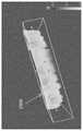
例如,本文描述了包括对辐射波长范围的半透明强散射区域(例如,牙齿)的对象重建体积结构的方法。该方法可以包括用发射(例如,专门或主要地辐射)穿透波长的光源照射对象,利用对穿透波长敏感的相机拍摄对象的多个图像(例如,在辐射波长范围内记录),对于多个图像中的每个图像接收表示相机相对于对象的位置的位置数据,针对体积中的每一个点根据多个图像和位置数据生成关于散射系数的上限,以及根据对于每个点的散射系数的上限生成对象的图像。施加到对象的光的穿透波长可以从与相机基本相同的方向发射。生成的一个或更多个图像可以示出在对象体积内的特征,并且图像还可以包括(或被修改以包括)对象的外边界以及内部结构。For example, described herein are methods of reconstructing the volumetric structure of an object that includes translucent, strongly scattering regions of the radiation wavelength range (eg, teeth). The method may include illuminating the subject with a light source emitting (eg, radiating exclusively or predominantly) at a penetration wavelength, taking a plurality of images of the subject (eg, recording in a range of radiation wavelengths) with a camera sensitive to the penetration wavelength, for multiple Each of the images receives position data representing the position of the camera relative to the object, generates an upper bound on the scatter coefficient for each point in the volume from the plurality of images and the position data, and generates an upper limit on the scatter coefficient from the plurality of images and the position data for each point in the volume, and from the scatter coefficient for each point The upper bound generates an image of the object. The penetrating wavelength of light applied to the object may be emitted from substantially the same direction as the camera. The generated one or more images may show features within the object volume, and the images may also include (or be modified to include) the object's outer boundaries and internal structures.
重建包括对于辐射波长范围的半透明强散射区域的对象的体积结构的方法可以包括:在辐射波长范围内用相机拍摄对象的多个图像,其中对多个图像的光照基本上从相机的方向投射,对于多个图像中的每个图像接收表示相机相对于对象的位置的位置数据,对于体积中的每一个点从多个图像和位置数据生成关于散射系数的上限,以及根据关于每一个点的散射系数的上限生成对象的图像。A method of reconstructing a volumetric structure of an object comprising translucent, strongly scattering regions for a radiation wavelength range may include taking, with a camera, a plurality of images of the object in the radiation wavelength range, wherein illumination for the plurality of images is projected substantially from the direction of the camera , receiving, for each of the plurality of images, position data representing the position of the camera relative to the object, generating an upper bound on the scattering coefficient from the plurality of images and the position data for each point in the volume, and The upper limit of the scattering coefficient produces an image of the object.
辐射波长的范围可以是红外或近红外波长。The range of radiation wavelengths can be infrared or near infrared wavelengths.
这些方法中的任何一种也可以包括接收表示对象的外表面的表面数据,其中针对对象的外表面内的体积中的每一个点执行生成步骤。Any of these methods may also include receiving surface data representing an outer surface of the object, wherein the generating step is performed for each point in the volume within the outer surface of the object.
该对象可以包括具有外部牙釉质表面和内部牙本质表面的牙齿。牙齿只是一种类型的包括半透明强散射区域的对象;其他示例可以包括其他两个组织(包括软组织和/或硬组织),例如骨骼等。这些包括半透明强散射区域的对象可以包括通常是半透明的并且对于穿透波长(例如,红外或近红外波长)是强散射的区域,如本文所述。The object may include a tooth having an outer enamel surface and an inner dentin surface. Teeth are just one type of object that includes translucent, highly scattering regions; other examples may include two other tissues (including soft and/or hard tissues), such as bone, and the like. These objects that include translucent strongly scattering regions may include regions that are generally translucent and strongly scatter for transmissive wavelengths (eg, infrared or near-infrared wavelengths), as described herein.
位置数据通常可以包括捕获多个图像中的每个图像时相机的位置和取向数据。例如,位置数据可以包括三维空间中的三个数值坐标以及相机的俯仰、偏航和滚动。The position data may generally include position and orientation data of the camera at the time each of the plurality of images was captured. For example, the position data may include three numerical coordinates in three-dimensional space and the pitch, yaw, and roll of the camera.
针对体积中的每个点生成关于散射系数的上限可以包括使用第一校准将与对象的体积相对应的点的3D网格的每个点投射到多个图像中的每一个图像上,产生对于每个投射点的强度值列表,根据体积响应将强度值列表上的每个强度值转换为散射系数,以及对于每个网格点存储来自散射系数值列表的最小散射系数值。Generating an upper limit on the scattering coefficient for each point in the volume may include projecting each point of the 3D grid of points corresponding to the volume of the object onto each of the plurality of images using a first calibration, resulting in a A list of intensity values for each projected point, converting each intensity value on the list of intensity values to a scattering coefficient according to the volume response, and storing the minimum scattering coefficient value from the list of scattering coefficient values for each grid point.
例如,第一校准可以包括用于校准传感器问题和相机的图像重影的固定模式噪声校准。第一校准可以包括相机校准,其确定对于将空间中的已知点投射到图像上的点的相机的变换。For example, the first calibration may include a fixed pattern noise calibration for calibrating sensor issues and camera image ghosting. The first calibration may include a camera calibration that determines a transformation of the camera to project a known point in space to a point on the image.
本文还描述了重建在辐射波长范围内半透明的牙齿的体积结构的方法,该方法包括在处理器中接收牙齿的表面在第一坐标系中的表示;在处理器中接收在辐射波长的范围内的多个图像,该多个图像采用基本上从相机的方向投射的光照进行拍摄;在该处理器中接收关于多个图像中的每个图像的表示相机的位置的位置数据;使用第一校准将与牙齿表面内的体积相对应的点的网格中的每个点投射到多个图像中的每一个图像上;产生对于每个投射点的强度值列表;将强度值列表上的每个强度值根据体积响应转换成散射系数;以及将对于每个点的最小散射系数存储到最小散射系数列表中。Also described herein is a method of reconstructing a volumetric structure of a tooth that is translucent in a range of radiation wavelengths, the method comprising receiving in a processor a representation of a surface of the tooth in a first coordinate system; receiving in the processor a range of radiation wavelengths a plurality of images within the plurality of images captured with lighting projected substantially from the direction of the camera; receiving in the processor position data representing the position of the camera for each of the plurality of images; using the first Calibrate projects each point in the grid of points corresponding to the volume within the tooth surface onto each of the plurality of images; generate a list of intensity values for each projected point; map each point on the list of intensity values The intensity values are converted into scattering coefficients according to the volume response; and the minimum scattering coefficients for each point are stored in a minimum scattering coefficient list.
这些方法中的任何一个还可以包括从最小散射系数列表中产生图像。Any of these methods may also include generating an image from a list of minimum scattering coefficients.
位置数据可以包括在捕获多个图像中的每一个图像时相机(或多个相机)的位置和取向数据。The position data may include position and orientation data of the camera (or cameras) at the time each of the plurality of images was captured.
第一校准可以包括固定模式噪声校准,以校准传感器问题和相机的图像重影。在一些实施例中,第一校准可以包括相机校准,其确定对于将空间中的已知点投射到图像上的点的相机的变换。The first calibration may include a fixed pattern noise calibration to correct for sensor issues and camera image ghosting. In some embodiments, the first calibration may include a camera calibration that determines a transformation of the camera to project a known point in space to a point on the image.
方法还可以包括接收表示对象的外表面的表面数据,其中投影步骤针对对象的外表面内的体积内部的每个点执行。The method may also include receiving surface data representing an outer surface of the object, wherein the projecting step is performed for each point inside the volume within the outer surface of the object.
点的网格可以包括立方网格。The grid of points may include a cubic grid.
本文描述的方法中的任一个可以被体现为软件、固件和/或硬件。例如,这些方法中的任何一个方法可以被配置为具有存储在其上的用于执行该方法的指令的非暂时性计算设备可读介质。Any of the methods described herein may be embodied in software, firmware and/or hardware. For example, any of these methods may be configured as a non-transitory computing device-readable medium having stored thereon instructions for performing the method.
例如,描述了一种具有存储在其上的指令的非暂时性计算设备可读介质,该指令用于在辐射波长范围内重建半透明的牙齿的体积结构。指令可以是由处理器可执行的以使计算设备接收牙齿的表面在第一坐标系中的表示,在辐射波长的范围内接收牙齿的多个图像,该多个图像用基本上从相机的方向投射的光照来拍摄,接收表示对于多个图像中的每个图像的相机的位置的位置数据,使用第一校准将与牙齿的体积相对应的点的网格中的每一个点投射到多个图像中的每一个图像上,产生对于每个投射点的强度值列表,根据体积响应将强度值列表上的每个强度值转换为散射系数,并将对于每一个点的最小散射系数存储到最小散射系数列表中,以及从最小散射系数列表中产生图像。For example, a non-transitory computing device readable medium having stored thereon instructions for reconstructing the volumetric structure of a translucent tooth in a range of radiation wavelengths is described. The instructions may be executable by the processor to cause the computing device to receive a representation of the surface of the tooth in the first coordinate system, to receive a plurality of images of the tooth over a range of radiation wavelengths, the plurality of images using directions substantially from the camera shooting with projected lighting, receiving position data representing the position of the camera for each of the plurality of images, projecting each point in the grid of points corresponding to the volume of the teeth to the plurality of images using a first calibration On each of the images, a list of intensity values for each projected point is generated, each intensity value on the list of intensity values is converted to a scattering coefficient according to the volume response, and the minimum scattering coefficient for each point is stored to the minimum from a list of scattering coefficients, and generate images from a list of minimum scattering coefficients.
位置数据可以包括在捕获多个近红外图像中的每一个近红外图像时相机的位置和取向数据。位置数据可以包括三维空间中的三个数值坐标以及相机的俯仰、偏航和滚动。The location data may include location and orientation data of the camera at the time each of the plurality of near-infrared images was captured. The position data can include three numerical coordinates in three-dimensional space and the pitch, yaw and roll of the camera.
第一校准可以包括固定模式噪声校准,以校准传感器问题和相机的图像重影。第一校准可以包括相机校准,其确定对于将空间中的已知点投射到图像上的点的相机的变换。The first calibration may include a fixed pattern noise calibration to correct for sensor issues and camera image ghosting. The first calibration may include a camera calibration that determines a transformation of the camera to project a known point in space to a point on the image.
点的网格可以在牙齿内;如上所述,点的网格可以包括立方网格。The grid of points may be within the tooth; as described above, the grid of points may comprise a cubic grid.
对于使用散射系数的替代或除此之外,使用穿透波长图像形成患者牙齿的内部结构的任何适当的方法。例如,本文描述的装置(例如,系统、设备、软件等)和方法中的任一个可以使用二维穿透图像以及关于扫描仪相对于被成像对象(例如,牙齿)的位置和/或取向信息,以分割2D穿透图像来形成包括牙齿内部的内部结构的牙齿的三维模型。如上所述,穿透图像可以指利用穿透对象的近IR和/或IR波长拍摄的图像。扫描仪的位置和/或取向可以是在扫描仪上(例如,在手持式棒上)上拍摄图像的摄像机的位置和/或取向的代表。Alternatively or in addition to using scattering coefficients, any suitable method of image formation of the internal structure of the patient's teeth using penetrating wavelengths. For example, any of the apparatuses (eg, systems, devices, software, etc.) and methods described herein may use two-dimensional penetrating images and information about the position and/or orientation of the scanner relative to the imaged object (eg, teeth) , to segment the 2D penetrating image to form a 3D model of the tooth including the internal structure inside the tooth. As discussed above, a penetrating image may refer to an image captured with near-IR and/or IR wavelengths that penetrate the subject. The position and/or orientation of the scanner may be representative of the position and/or orientation of a camera on the scanner (eg, on a handheld wand) that captures images.
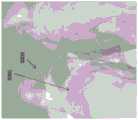
例如,本文描述了对受试者的牙齿进行建模的方法,包括:用口内扫描仪捕获受试者的牙齿的内部的多个图像以及口内扫描仪的特定于多个图像中的每个图像的位置和取向;分割多个图像以形成对应于受试者牙齿内的结构的内部结构;使用多个图像的位置和取向将内部结构投射到受试者的牙齿的三维模型上;以及显示包括内部结构的受试者的牙齿的三维模型。For example, described herein is a method of modeling a subject's teeth comprising: capturing with an intraoral scanner a plurality of images of the interior of the subject's teeth and each image of the intraoral scanner specific to the plurality of images position and orientation of the multiple images; segment the plurality of images to form internal structures corresponding to structures within the subject's teeth; use the positions and orientations of the multiple images to project the internal structures onto the three-dimensional model of the subject's teeth; Three-dimensional model of the internal structure of the subject's teeth.
在这些方法和装置中的任一个中,可以在捕获穿透图像的同时使用非穿透波长(例如,表面扫描)同时捕获3D表面模型。例如,捕获可以包括捕获受试者的牙齿的表面图像同时捕获受试者的牙齿的内部的多个图像。方法还可以包括从所捕获的表面图像形成受试者的牙齿的三维模型。例如,形成受试者的牙齿的三维模型可以包括使用共焦聚焦来确定三维表面拓扑。捕获受试者的牙齿的表面图像可以包括使用共焦扫描、立体视觉或结构光三角测量。In any of these methods and apparatus, a 3D surface model can be captured simultaneously using a non-penetrating wavelength (eg, surface scanning) while capturing a penetrating image. For example, capturing may include capturing surface images of the subject's teeth while capturing multiple images of the interior of the subject's teeth. The method may also include forming a three-dimensional model of the subject's teeth from the captured surface images. For example, forming a three-dimensional model of a subject's teeth may include using confocal focusing to determine three-dimensional surface topology. Capturing surface images of the subject's teeth may include using confocal scanning, stereo vision, or structured light triangulation.
通常,相同的设备(例如,扫描仪)可以建模和/或显示包括内部结构的牙齿的3D表示,或者可选地或附加地可以使用单独的处理器(例如,远离扫描仪)。这些方法中的任一种方法还可以包括在捕获多个二维图像的同时存储和/或传输多个穿透图像和口内扫描仪的位置和取向,包括向远程处理器传输以执行分割和后续步骤。Typically, the same device (eg, scanner) can model and/or display a 3D representation of the tooth including the internal structure, or a separate processor (eg, remote from the scanner) may alternatively or additionally be used. Any of these methods may also include storing and/or transmitting the plurality of penetration images and the position and orientation of the intraoral scanner while capturing the plurality of two-dimensional images, including transmitting to a remote processor to perform segmentation and subsequent step.
在本文描述的方法和装置的任一个中,可以在扫描仪操作的同时显示包括内部结构的3D模型。这可以有利地允许用户实时或接近实时地查看受试者的牙齿中的内部结构。因此,这些方法中的任一种方法可以包括在捕获图像时显示三维模型。In any of the methods and apparatus described herein, a 3D model including internal structures can be displayed while the scanner is operating. This may advantageously allow the user to view the internal structures in the subject's teeth in real time or near real time. Accordingly, any of these methods may include displaying the three-dimensional model as the image is captured.
分割多个图像可以包括对多个图像应用边缘检测以识别多个图像内的封闭边界。分割多个图像可以包括从多个图像形成体积密度图以识别内部结构。分割体积密度图可以包括通过识别体积密度图内的一个或更多个等值面来分割,以识别内部特征。这些方法中的任何一种方法可以包括分割体积密度图以识别内部特征(例如,裂纹、龋齿、牙填充体、牙本质等)。Segmenting the plurality of images may include applying edge detection to the plurality of images to identify closed boundaries within the plurality of images. Segmenting the plurality of images may include forming a volume density map from the plurality of images to identify internal structures. Segmenting the bulk density map may include segmenting by identifying one or more isosurfaces within the bulk density map to identify internal features. Any of these methods may include segmenting the volume density map to identify internal features (eg, cracks, caries, dental fillings, dentin, etc.).
如上所述,捕获多个图像可以包括使用穿透波长和口内扫描仪。捕获多个图像可以包括捕获红外图像和/或近红外图像。As described above, capturing multiple images may include the use of penetrating wavelengths and intraoral scanners. Capturing multiple images may include capturing infrared images and/or near infrared images.
例如,配置成生成受试者的牙齿的模型的口内扫描装置可以包括:口内扫描仪,其具有多个光源以及位置和取向传感器,其中光源被配置为以第一光谱范围和第二光谱范围发射光,而且其中第二光谱范围是穿透的;以及可操作地连接到口内扫描仪的处理器,处理器被配置为当口内扫描仪以第二光谱范围发射光时,使扫描仪捕获多个图像以及与多个图像中的每一个图像相对应的口内扫描仪的位置和取向;其中处理器还被配置为分割多个图像以形成对应于受试者的牙齿内的结构的内部结构,并且显示或传输包括内部结构的受试者的牙齿的三维模型。For example, an intraoral scanning device configured to generate a model of a subject's teeth may include an intraoral scanner having a plurality of light sources and position and orientation sensors, wherein the light sources are configured to emit in a first spectral range and a second spectral range light, and wherein the second spectral range is penetrating; and a processor operably connected to the intraoral scanner, the processor configured to cause the scanner to capture a plurality of light when the intraoral scanner emits light in the second spectral range the image and the position and orientation of the intraoral scanner corresponding to each of the plurality of images; wherein the processor is further configured to segment the plurality of images to form internal structures corresponding to structures within the subject's teeth, and A three-dimensional model of the subject's teeth including internal structures is displayed or transmitted.
处理器可以被配置为通过对多个图像应用边缘检测以识别多个图像内的封闭边界来分割多个图像。处理器可以被配置为通过从多个图像形成像素密度图来分割多个图像以识别内部结构。处理器可以被配置为识别像素密度图内的封闭段以识别内部结构。The processor may be configured to segment the plurality of images by applying edge detection to the plurality of images to identify closed boundaries within the plurality of images. The processor may be configured to segment the plurality of images to identify internal structures by forming pixel density maps from the plurality of images. The processor may be configured to identify closed segments within the pixel density map to identify internal structures.
本文还描述了具有存储在其上的指令的非暂时性计算设备可读介质,所述指令可由处理器执行以使口内扫描装置能够:使用光的穿透波长捕获多个图像和口内扫描仪的特定于多个图像中的每个图像的位置和取向;分割多个图像以形成对应于受试者的牙齿内的结构的内部结构;使用特定于每个图像的口内扫描仪的位置和取向将内部结构投射到受试者的牙齿的三维模型上;并显示受试者的牙齿的包括内部结构的三维模型。Also described herein is a non-transitory computing device readable medium having stored thereon instructions executable by a processor to enable an intraoral scanning device to: capture a plurality of images and an intraoral scanner using transmissive wavelengths of light position and orientation specific to each of the plurality of images; segment the plurality of images to form internal structures corresponding to structures within the subject's teeth; use the position and orientation of the intraoral scanner specific to each image to The internal structure is projected onto the three-dimensional model of the subject's teeth; and the three-dimensional model of the subject's teeth including the internal structure is displayed.
具有指令的非暂时性计算设备可读介质还可以被配置为使口内扫描装置通过对多个图像应用边缘检测以识别多个图像内的封闭边界来分割多个图像。具有指令的非暂时性计算设备可读介质还可以被配置成使口内扫描装置通过从多个图像形成像素密度图来分割多个图像以形成内部结构。具有指令的非暂时性计算设备可读介质还可以被配置为使口内扫描装置通过识别像素密度图内的封闭段来分割多个图像以形成内部结构。The non-transitory computing device readable medium with instructions may also be configured to cause the intraoral scanning device to segment the plurality of images by applying edge detection to the plurality of images to identify closed boundaries within the plurality of images. The non-transitory computing device readable medium having the instructions may also be configured to cause the intraoral scanning device to segment the plurality of images to form the internal structure by forming a pixel density map from the plurality of images. The non-transitory computing device readable medium having the instructions may also be configured to cause the intraoral scanning device to segment the plurality of images to form the internal structure by identifying closed segments within the pixel density map.
本文还描述了具有其上存储有指令的非暂时性计算设备可读介质,该指令可由处理器执行以使计算设备:从扫描仪接收受试者的牙齿的三维表面模型数据;从扫描仪接收受试者的牙齿的内部的多个图像以及口内扫描仪的特定于多个图像中的每个图像的位置和取向;分割多个图像以形成受试者的牙齿的内部结构;将受试者的牙齿的内部结构投射到三维表面模型上;并显示示出内部结构的三维表面模型。Also described herein is a non-transitory computing device-readable medium having stored thereon instructions executable by a processor to cause a computing device to: receive from a scanner three-dimensional surface model data of a subject's teeth; receive from the scanner Multiple images of the interior of the subject's teeth and position and orientation of the intraoral scanner specific to each of the multiple images; segmenting the multiple images to form the interior of the subject's teeth; The internal structure of the tooth is projected onto the three-dimensional surface model; and the three-dimensional surface model showing the internal structure is displayed.
1.一种用于生成受试者的牙齿的模型的方法,所述方法包括:1. A method for generating a model of a subject's teeth, the method comprising:
使用口内扫描仪捕获受试者的牙齿的至少一部分的三维(3D)表面模型数据;capturing three-dimensional (3D) surface model data of at least a portion of the subject's teeth using an intraoral scanner;
利用所述口内扫描仪使用穿透波长对所述牙齿拍摄多个图像;以及Taking a plurality of images of the tooth using the penetrating wavelength with the intraoral scanner; and
使用所述3D表面模型数据和所述多个图像来形成包括内部结构的所述牙齿的3D模型。A 3D model of the tooth including internal structure is formed using the 3D surface model data and the plurality of images.
2.一种用于生成受试者的牙齿的模型的方法,所述方法包括:2. A method for generating a model of a subject's teeth, the method comprising:
利用在第一成像模态下操作的口内扫描仪捕获受试者的牙齿的至少一部分的三维(3D)表面模型数据,其中所述3D表面模型数据具有第一坐标系;Using an intraoral scanner operating in a first imaging modality to capture three-dimensional (3D) surface model data of at least a portion of the subject's teeth, wherein the 3D surface model data has a first coordinate system;
使用穿透波长利用第二成像模态下操作的所述口内扫描仪对所述牙齿拍摄多个图像,其中所述多个图像参考所述第一坐标系;以及capturing a plurality of images of the tooth with the intraoral scanner operating in a second imaging modality using a transmission wavelength, wherein the plurality of images are referenced to the first coordinate system; and
使用所述3D表面模型数据和所述多个图像来形成包括内部结构的所述牙齿的3D模型。A 3D model of the tooth including internal structure is formed using the 3D surface model data and the plurality of images.
3.根据1或2所述的方法,其中,捕获所述3D表面模型数据包括使用共焦聚焦来确定3D表面拓扑。3. The method of 1 or 2, wherein capturing the 3D surface model data comprises using confocal focusing to determine 3D surface topology.
4.根据1或2所述的方法,其中,捕获所述3D表面模型数据包括使用共焦扫描、立体视觉或结构光三角测量。4. The method of 1 or 2, wherein capturing the 3D surface model data comprises using confocal scanning, stereo vision or structured light triangulation.
5.根据1或2所述的方法,其中,捕获所述3D表面模型数据包括捕获所述牙齿和牙龈的模型。5. The method of 1 or 2, wherein capturing the 3D surface model data comprises capturing models of the teeth and gums.
6.根据1或2所述的方法,其中,捕获所述3D表面模型数据包括捕获彩色口内3D模型。6. The method of 1 or 2, wherein capturing the 3D surface model data comprises capturing a color intraoral 3D model.
7.根据2所述的方法,其中,拍摄所述多个图像包括通过在所述第一成像模态和所述第二成像模态之间切换在所述3D表面模型数据被捕获时使用所述穿透波长拍摄图像。7. The method of 2, wherein capturing the plurality of images comprises using the 3D surface model data as the 3D surface model data is captured by switching between the first imaging modality and the second imaging modality. Images were taken at the above-mentioned transmission wavelength.
8.根据1或2所述的方法,其中,拍摄所述多个图像包括使用所述口内扫描仪上的相同的传感器来捕获3D表面模型数据和使用所述穿透波长的所述多个图像。8. The method of 1 or 2, wherein capturing the plurality of images comprises capturing 3D surface model data and the plurality of images using the transmission wavelength using the same sensor on the intraoral scanner .
9.根据1或2所述的方法,其中,拍摄所述多个图像包括相对于接收照射的传感器以0°和15°之间的角度照射所述牙齿。9. The method of 1 or 2, wherein capturing the plurality of images comprises illuminating the tooth at an angle between 0° and 15° relative to a sensor receiving the illumination.
10.根据1或2所述的方法,其中,拍摄所述多个图像包括在所述口内扫描仪的相对于所述牙齿的每个位置处拍摄多个透照图像或小角度穿透图像。10. The method of 1 or 2, wherein capturing the plurality of images comprises capturing a plurality of transillumination or low angle penetration images at each position of the intraoral scanner relative to the teeth.
11.根据1或2所述的方法,其中,拍摄所述多个图像包括在所述口内扫描仪上使用不同的传感器来捕获3D表面模型数据和使用所述穿透波长的所述多个图像。11. The method of 1 or 2, wherein capturing the plurality of images comprises using different sensors on the intraoral scanner to capture 3D surface model data and the plurality of images using the transmission wavelengths .
12.根据1或2所述的方法,其中,拍摄所述多个图像包括在所述口内扫描仪上使用多个传感器以使用所述穿透波长来捕获所述多个图像。12. The method of 1 or 2, wherein capturing the plurality of images comprises using a plurality of sensors on the intraoral scanner to capture the plurality of images using the transmission wavelength.
13.根据1或2所述的方法,其中,拍摄所述多个图像包括利用白光透照、UV/蓝荧光和红色光荧光中的一种或更多种来照射所述牙齿。13. The method of 1 or 2, wherein capturing the plurality of images comprises illuminating the tooth with one or more of white light transillumination, UV/blue fluorescence, and red light fluorescence.
14.根据1或2所述的方法,其中,拍摄所述多个图像包括利用红外光照射所述牙齿。14. The method of 1 or 2, wherein capturing the plurality of images comprises illuminating the teeth with infrared light.
15.根据1或2所述的方法,其中,形成包括内部结构的所述牙齿的 3D模型包括将所述3D表面模型数据与所述内部结构的3D模型组合。15. The method of 1 or 2, wherein forming a 3D model of the tooth including an internal structure comprises combining the 3D surface model data with a 3D model of the internal structure.
16.根据1或2所述的方法,其中,形成包括内部结构的所述牙齿的 3D模型包括组合所述多个图像,其中所述多个图像使用所述口内扫描仪从多个角度拍摄。16. The method of 1 or 2, wherein forming a 3D model of the tooth including an internal structure comprises combining the plurality of images, wherein the plurality of images were taken from a plurality of angles using the intraoral scanner.
17.根据1或2所述的方法,还包括标记内部结构。17. The method of 1 or 2, further comprising marking internal structures.
18.一种用于生成受试者的牙齿的模型的口内扫描系统,所述系统包括:18. An intraoral scanning system for generating a model of a subject's teeth, the system comprising:
手持式棒,所述手持式棒具有至少一个传感器和多个光源,其中所述光源被配置为发射第一光谱范围和第二光谱范围的光,其中所述第二光谱范围是穿透的;以及a hand-held wand having at least one sensor and a plurality of light sources, wherein the light sources are configured to emit light in a first spectral range and a second spectral range, wherein the second spectral range is transmissive; as well as
一个或更多个处理器,所述一个或更多个处理器可操作地连接到所述手持式棒,所述一个或更多个处理器被配置为:one or more processors operably connected to the hand-held wand, the one or more processors configured to:
使用来自第一光谱范围的光生成受试者的牙齿的至少一部分的三维 (3D)表面模型;和generating a three-dimensional (3D) surface model of at least a portion of the subject's teeth using light from the first spectral range; and
基于所述3D表面模型以及基于以显示内部结构的所述第二光谱范围拍摄的多个图像生成包括内部结构的所述受试者的牙齿的3D模型。A 3D model of the subject's teeth including internal structures is generated based on the 3D surface model and based on a plurality of images taken in the second spectral range showing internal structures.
19.一种用于生成受试者的牙齿的模型的口内扫描仪系统,所述系统包括:19. An intraoral scanner system for generating a model of a subject's teeth, the system comprising:
手持式棒,所述手持式棒具有至少一个传感器和多个光源,其中所述光源被配置为发射第一光谱范围和第二光谱范围的光,而且其中所述第二光谱范围是穿透的;以及a hand-held wand having at least one sensor and a plurality of light sources, wherein the light sources are configured to emit light in a first spectral range and a second spectral range, and wherein the second spectral range is transmissive ;as well as
一个或更多个处理器,所述一个或更多个处理器可操作地连接到所述手持式棒,所述一个或更多个处理器被配置为:one or more processors operably connected to the hand-held wand, the one or more processors configured to:
使用第一坐标系,通过使用由所述手持式棒感测到的所述第一光谱范围内的光来确定表面信息;using a first coordinate system, determining surface information by using light in the first spectral range sensed by the hand-held wand;
使用所述表面信息来生成受试者的牙齿的至少一部分的三维(3D)表面模型;generating a three-dimensional (3D) surface model of at least a portion of the subject's teeth using the surface information;
在所述第二光谱范围内拍摄多个图像,其中所述图像参考所述第一坐标系;并且capturing a plurality of images in the second spectral range, wherein the images are referenced to the first coordinate system; and
基于所述3D表面模型和所述多个图像生成包括内部结构的所述受试者的牙齿的3D模型。A 3D model of the subject's teeth including internal structures is generated based on the 3D surface model and the plurality of images.
20.根据18或19所述的系统,其中,所述手持式棒包括多个传感器。20. The system of 18 or 19, wherein the hand-held wand comprises a plurality of sensors.
21.根据18或19所述的系统,其中,所述一个或更多个处理器被配置为通过使用共焦聚焦来确定表面信息。21. The system of 18 or 19, wherein the one or more processors are configured to determine surface information using confocal focusing.
22.根据18或19所述的系统,其中,所述一个或更多个处理器被配置为通过使用共焦扫描、立体视觉或结构光三角测量来确定表面信息。22. The system of 18 or 19, wherein the one or more processors are configured to determine surface information using confocal scanning, stereo vision or structured light triangulation.
23.根据18或19所述的系统,其中,所述手持式棒被配置为通过在所述第一光谱范围和所述第二光谱范围之间切换而在发射所述第一光谱范围的光以执行表面扫描和发射所述第二光谱范围的光以检测内部结构之间循环,使得利用所述第二光谱范围拍摄的图像与所述表面扫描共享坐标系。23. The system of 18 or 19, wherein the hand-held wand is configured to emit light in the first spectral range by switching between the first spectral range and the second spectral range Cycling between performing a surface scan and emitting light in the second spectral range to detect internal structures such that images captured using the second spectral range share a coordinate system with the surface scan.
24.根据18或19所述的系统,其中,所述至少一个传感器被配置为捕获所述3D表面模型数据和所述牙齿的所述内部数据二者。24. The system of 18 or 19, wherein the at least one sensor is configured to capture both the 3D surface model data and the internal data of the tooth.
25.根据18或19所述的系统,其中,所述至少一个传感器包括第一传感器和第二传感器,所述第一传感器被配置为捕获来自所述第一光谱范围的光的所述3D表面模型数据,所述第二传感器被配置为捕获来自所述第二光谱范围的光的所述牙齿的所述内部数据。25. The system of 18 or 19, wherein the at least one sensor comprises a first sensor and a second sensor, the first sensor configured to capture the 3D surface of light from the first spectral range model data, the second sensor configured to capture the internal data of the tooth from the second spectral range of light.
26.根据18或19所述的系统,还包括与所述多个光源相邻的多个传感器。26. The system of 18 or 19, further comprising a plurality of sensors adjacent the plurality of light sources.
27.根据18或19所述的系统,其中,被配置为发射所述第二光谱范围的光的所述光源被配置为发射以下中的一种或更多种:白光透照、UV/ 蓝荧光和红光荧光。27. The system of 18 or 19, wherein the light source configured to emit light in the second spectral range is configured to emit one or more of the following: white light transillumination, UV/blue light Fluorescence and red fluorescence.
28.根据18或19所述的系统,其中,被配置为发射所述第二光谱范围的光的所述光源被配置为发射红外光。28. The system of 18 or 19, wherein the light source configured to emit light in the second spectral range is configured to emit infrared light.
29.根据18或19所述的系统,而且其中,所述多个光源和所述至少一个传感器布置在所述手持式棒上,使得在所述第二光谱范围内发射的光从牙齿反射并被所述一个或更多个传感器以0°和15°之间的角度接收。29. The system of 18 or 19, and wherein the plurality of light sources and the at least one sensor are arranged on the hand-held wand such that light emitted in the second spectral range is reflected from teeth and received by the one or more sensors at an angle between 0° and 15°.
30.一种用于生成受试者的牙齿的模型的方法,所述方法包括:30. A method for generating a model of a subject's teeth, the method comprising:
使用口内扫描仪以使用第一模态来扫描受试者的牙齿的一部分,以捕获所述牙齿的三维(3D)表面模型数据;using an intraoral scanner to scan a portion of a subject's teeth using a first modality to capture three-dimensional (3D) surface model data of the teeth;
使用所述口内扫描仪以使用第二模态来扫描所述受试者的牙齿的所述一部分,以使用穿透波长对所述牙齿成像来捕获所述牙齿的内部数据;using the intraoral scanner to scan the portion of the subject's tooth using a second modality to capture internal data of the tooth by imaging the tooth using a penetrating wavelength;
在所述第一模态和所述第二模态之间循环,其中循环在所述第一模态和所述第二模态之间快速切换,使得使用所述穿透波长的图像与在所述第一模态中捕获的所述3D表面模型数据共享坐标系。cycling between the first modality and the second modality, wherein cycling rapidly switches between the first modality and the second modality such that the image using the transmitted wavelength is The 3D surface model data captured in the first modality shares a coordinate system.
31.一种用于生成受试者的牙齿的模型的方法,所述方法包括:31. A method for generating a model of a subject's teeth, the method comprising:
使用手持式口内扫描仪以使用第一模态扫描受试者的牙齿的一部分,以捕获所述牙齿的三维(3D)表面模型数据;using a handheld intraoral scanner to scan a portion of a subject's teeth using a first modality to capture three-dimensional (3D) surface model data of the teeth;
使用所述手持式口内扫描仪以使用第二模态扫描所述受试者的牙齿的所述一部分,以使用穿透波长对所述牙齿成像来捕获所述牙齿的内部数据;using the handheld intraoral scanner to scan the portion of the subject's teeth using a second modality to capture internal data of the teeth by imaging the teeth using penetrating wavelengths;
使用扫描方案在所述第一模态和所述第二模态之间循环,其中循环在所述第一模态和所述第二模态之间快速切换,使得所述内部数据使用与在所述第一模态中捕获的所述3D表面模型数据相同的坐标系;并且Cycling between the first modality and the second modality using a scan scheme, wherein cycling rapidly switches between the first modality and the second modality such that the internal data usage is the same as in the the same coordinate system as the 3D surface model data captured in the first modality; and
基于所捕获的3D表面模型数据、所述内部数据、或所述3D表面模型数据和所述内部数据两者来调整所述扫描方案。The scan protocol is adjusted based on the captured 3D surface model data, the interior data, or both the 3D surface model data and the interior data.
32.根据30或31所述的方法,还包括组合所述3D表面模型数据和所述牙齿的所述内部数据以形成所述牙齿的3D模型。32. The method of 30 or 31, further comprising combining the 3D surface model data and the internal data of the tooth to form a 3D model of the tooth.
33.根据30或31所述的方法,还包括组合所述3D表面模型数据和所述牙齿的所述内部数据以形成所述牙齿的3D模型以及标记内部结构。33. The method of 30 or 31, further comprising combining the 3D surface model data and the internal data of the tooth to form a 3D model of the tooth and marking internal structures.
34.根据30或31所述的方法,其中,捕获所述3D表面模型数据包括使用共焦聚焦来确定3D表面拓扑。34. The method of 30 or 31, wherein capturing the 3D surface model data comprises using confocal focusing to determine 3D surface topology.
35.根据30或31所述的方法,其中,捕获所述3D表面模型数据包括使用共焦扫描、立体视觉或结构光三角测量。35. The method of 30 or 31, wherein capturing the 3D surface model data comprises using confocal scanning, stereo vision or structured light triangulation.
36.根据30或31所述的方法,还包括扫描所述受试者的牙齿和牙龈。36. The method of 30 or 31, further comprising scanning the subject's teeth and gums.
37.根据30或31所述的方法,而且其中,循环包括在所述第一模态、所述第二模态和第三模态之间循环,其中循环在所述第一模态、所述第二模态和所述第三模态之间快速循环,使得使用所述穿透波长的图像与在所述第一模态中捕获的所述3D表面模型共享坐标系。37. The method of 30 or 31, and wherein cycling comprises cycling between the first, second and third modes, wherein cycling between the first, all Cycling rapidly between the second modality and the third modality such that the image using the penetrating wavelength shares a coordinate system with the 3D surface model captured in the first modality.
38.根据30或31所述的方法,还包括使用所述口内扫描仪以使用第三模态扫描所述受试者的牙齿的所述一部分以捕获所述受试者的牙齿的可视图像。38. The method of 30 or 31, further comprising using the intraoral scanner to scan the portion of the subject's teeth using a third modality to capture a visual image of the subject's teeth .
39.根据30或31所述的方法,还包括使用所述口内扫描仪上的传感器来捕获所述3D表面模型数据和所述牙齿的所述内部数据二者。39. The method of 30 or 31, further comprising capturing both the 3D surface model data and the internal data of the tooth using sensors on the intraoral scanner.
40.根据30或31所述的方法,其中,使用所述口内扫描仪以使用所述第二模态扫描所述受试者的牙齿的所述一部分包括相对于接收照射的传感器以0°和15°之间的角度照射所述牙齿。40. The method of 30 or 31, wherein using the intraoral scanner to scan the portion of the subject's teeth using the second modality comprises at 0° and 0° relative to the sensor receiving the illumination. The teeth are illuminated at an angle between 15°.
41.根据30或31所述的方法,其中,使用所述口内扫描仪以使用所述第二模态扫描所述受试者的牙齿的所述一部分包括以照射源和传感器之间的多个不同的角度拍摄多个透照图像或小角度穿透图像。41. The method of 30 or 31 , wherein using the intraoral scanner to scan the portion of the subject's teeth using the second modality comprises taking multiples between an illumination source and a sensor. Multiple transillumination images or small-angle penetration images are taken at different angles.
42.根据30或31所述的方法,还包括使用所述口内扫描仪上的不同的传感器来捕获所述3D表面模型数据和所述牙齿的所述内部数据。42. The method of 30 or 31, further comprising capturing the 3D surface model data and the internal data of the tooth using different sensors on the intraoral scanner.
43.根据30或31所述的方法,还包括使用所述口内扫描仪上的多个传感器来捕获所述牙齿的内部数据。43. The method of 30 or 31, further comprising capturing internal data of the teeth using a plurality of sensors on the intraoral scanner.
44.根据30或31所述的方法,其中,使用所述口内扫描仪以使用所述第二模态扫描所述受试者的牙齿的所述一部分包括利用以下中的一种或更多种进行照射:白光透照、UV/蓝荧光和红光荧光。44. The method of 30 or 31, wherein using the intraoral scanner to scan the portion of the subject's teeth using the second modality comprises utilizing one or more of Irradiation was performed: white light transillumination, UV/blue fluorescence, and red fluorescence.
45.根据30或31所述的方法,其中,使用所述口内扫描仪以使用所述第二模态扫描所述受试者的牙齿的所述一部分包括利用红外光进行照射。45. The method of 30 or 31, wherein using the intraoral scanner to scan the portion of the subject's teeth using the second modality comprises illuminating with infrared light.
46.根据30所述的方法,还包括自动调整以第一模态进行扫描所花费的持续时间、以所述第二模态进行扫描所花费的持续时间、或当在所述第一模态和所述第二模态之间循环时以所述第一模态和所述第二模态进行扫描所花费的持续时间。46. The method of 30, further comprising automatically adjusting the duration spent scanning in the first modality, the duration spent scanning in the second modality, or when in the first modality The duration of time spent scanning in the first modality and the second modality while cycling between the modalities and the second modality.
47.根据30所述的方法,还包括基于所捕获的3D表面模型数据、所述内部数据、或所述3D表面模型数据和所述内部数据两者来自动调整以第一模态进行扫描所花费的持续时间、以所述第二模态进行扫描所花费的持续时间、或当在所述第一模态和所述第二模态之间循环时以所述第一模态和所述第二模态所花费的持续时间。47. The method of 30, further comprising automatically adjusting the scanning method in the first modality based on the captured 3D surface model data, the interior data, or both the 3D surface model data and the interior data. The duration spent, the duration spent scanning in the second modality, or in the first modality and the second modality when cycling between the first modality and the second modality Duration spent in the second modality.
48.根据31所述的方法,其中,调整所述扫描方案包括基于关于对所捕获的3D表面模型数据的质量的确定的质量来进行调整。48. The method of 31, wherein adjusting the scanning scheme comprises adjusting based on a determined quality regarding the quality of the captured 3D surface model data.
49.根据31所述的方法,其中,调整所述扫描方案包括自动调整所述扫描方案。49. The method of 31, wherein adjusting the scanning scheme comprises automatically adjusting the scanning scheme.
50.根据31所述的方法,其中,调整所述扫描方案包括调整以所述第一模态进行扫描的持续时间。50. The method of 31, wherein adjusting the scanning protocol comprises adjusting the duration of scanning in the first modality.
51.根据31所述的方法,其中,调整所述扫描方案包括调整以所述第二模态进行扫描的持续时间。51. The method of 31, wherein adjusting the scanning protocol comprises adjusting a duration of scanning in the second modality.
52.一种用于生成受试者的牙齿的模型的口内扫描系统,所述系统包括:52. An intraoral scanning system for generating a model of a subject's teeth, the system comprising:
手持式口内棒,所述手持式口内棒具有至少一个传感器和多个光源,其中所述光源被配置为发射在第一光谱范围和在第二光谱范围的光,而且其中所述第二光谱范围是穿透的;以及a hand-held intraoral wand having at least one sensor and a plurality of light sources, wherein the light sources are configured to emit light in a first spectral range and in a second spectral range, and wherein the second spectral range is penetrating; and
一个或更多个处理器,所述一个或更多个处理器可操作地连接到所述手持式口内棒,所述一个或更多个处理器被配置为使所述棒在第一模式和第二模式之间循环,其中在所述第一模式中,所述棒在第一持续时间内发射所述第一光谱范围的光并且所述一个或更多个处理器接收三维(3D)表面数据作为响应,并且其中在所述第二模式中,所述棒在第二持续时间内发射在第二光谱范围内的光并且所述一个或更多个处理器接收图像数据作为响应。one or more processors operably connected to the hand-held intraoral wand, the one or more processors configured to place the wand in a first mode and Cycling between second modes in which the rod emits light in the first spectral range for a first duration and the one or more processors receive a three-dimensional (3D) surface data in response, and wherein in the second mode, the wand emits light in a second spectral range for a second duration and the one or more processors receive image data in response.
53.一种用于生成受试者的牙齿的模型的口内扫描系统,所述系统包括:53. An intraoral scanning system for generating a model of a subject's teeth, the system comprising:
手持式口内棒,所述手持式口内棒具有至少一个传感器和多个光源,其中所述光源被配置为发射在第一光谱范围和在第二光谱范围的光,而且其中所述第二光谱范围是穿透的;以及a hand-held intraoral wand having at least one sensor and a plurality of light sources, wherein the light sources are configured to emit light in a first spectral range and in a second spectral range, and wherein the second spectral range is penetrating; and
一个或更多个处理器,所述一个或更多个处理器可操作地连接到所述棒,所述一个或更多个处理器被配置为使所述棒在第一模式和第二模式之间循环,其中在所述第一模式中,所述棒在第一持续时间内发射在所述第一光谱范围的光并且所述一个或更多个处理器接收三维(3D)表面数据作为响应,并且其中在所述第二模式中,所述棒在第二持续时间内发射在所述第二光谱范围的光并且所述一个或更多个处理器接收图像数据作为响应;one or more processors operably connected to the wand, the one or more processors configured to place the wand in a first mode and a second mode cycles between wherein, in the first mode, the rod emits light in the first spectral range for a first duration and the one or more processors receive three-dimensional (3D) surface data as responding, and wherein in the second mode, the wand emits light in the second spectral range for a second duration and the one or more processors receive image data in response;
其中,所述一个或更多个处理器被配置为基于所接收的3D表面数据、所接收的图像数据、或者所述3D表面数据和所述图像数据二者来调整所述第一持续时间和所述第二持续时间。wherein the one or more processors are configured to adjust the first duration and the the second duration.
54.根据52或53所述的系统,其中,所述棒包括多个传感器。54. The system of 52 or 53, wherein the wand comprises a plurality of sensors.
55.根据52或53所述的系统,其中,所述一个或更多个处理器被配置为使用共焦聚焦来确定来自所述三维(3D)表面数据的表面信息。55. The system of 52 or 53, wherein the one or more processors are configured to use confocal focusing to determine surface information from the three-dimensional (3D) surface data.
56.根据52或53所述的系统,其中,所述一个或更多个处理器被配置为通过使用共焦扫描、立体视觉或结构光三角测量来确定作为响应的来自所述三维(3D)表面数据的表面信息。56. The system of 52 or 53, wherein the one or more processors are configured to determine, in response, from the three-dimensional (3D) Surface information for surface data.
57.根据52或53所述的系统,其中,所述第一持续时间和所述第二持续时间被设定成使得在所述第二光谱范围处拍摄的所述图像数据与在所述第一光谱范围处拍摄的所述3D表面数据共享坐标系。57. The system of 52 or 53, wherein the first duration and the second duration are set such that the image data captured at the second spectral range is The 3D surface data captured at a spectral range share a coordinate system.
58.根据52或53所述的系统,其中,所述第一持续时间和所述第二持续时间小于100毫秒,使得在所述第二光谱范围处拍摄的所述图像数据与在所述第一光谱范围处拍摄的所述3D表面数据共享坐标系。58. The system of 52 or 53, wherein the first duration and the second duration are less than 100 milliseconds such that the image data captured at the second spectral range is The 3D surface data captured at a spectral range share a coordinate system.
59.根据52或53所述的系统,其中,所述至少一个传感器被配置成捕获所述3D表面模型数据和所述牙齿的所述内部数据二者。59. The system of 52 or 53, wherein the at least one sensor is configured to capture both the 3D surface model data and the internal data of the tooth.
60.根据52或53所述的系统,其中,所述至少一个传感器包括被配置为捕获来自所述第一光谱范围的光的所述3D表面模型数据的第一传感器和被配置为捕获来自所述第二光谱范围的光的所述牙齿的所述内部数据的第二传感器。60. The system of 52 or 53, wherein the at least one sensor comprises a first sensor configured to capture the 3D surface model data of light from the first spectral range and a first sensor configured to capture data from the 3D surface model of light from the first spectral range. and a second sensor for said internal data of said tooth of said second spectral range of light.
61.根据52或53所述的系统,还包括与所述多个光源相邻的多个传感器。61. The system of 52 or 53, further comprising a plurality of sensors adjacent the plurality of light sources.
62.根据52或53所述的系统,其中,被配置为发射所述第二光谱范围处的光的所述光源被配置为发射以下中的一种或更多种:白光透照、UV/ 蓝荧光和红光荧光。62. The system of 52 or 53, wherein the light source configured to emit light at the second spectral range is configured to emit one or more of the following: white light transillumination, UV/ Blue and red fluorescence.
63.根据52或53所述的系统,其中,被配置为发射所述第二光谱范围处的光的所述光源被配置为发射红外光。63. The system of 52 or 53, wherein the light source configured to emit light at the second spectral range is configured to emit infrared light.
64.根据52或53所述的系统,而且其中,所述多个光源和所述至少一个传感器布置在所述手持式棒上,使得在所述第二光谱范围处发射的光从牙齿被反射并被所述一个或更多个传感器以0°和15°之间的角度接收。64. The system of 52 or 53, and wherein the plurality of light sources and the at least one sensor are arranged on the hand-held wand such that light emitted at the second spectral range is reflected from teeth and received by the one or more sensors at an angle between 0° and 15°.
65.根据52或53所述的系统,其中,所述处理器被配置成根据所述三维(3D)表面数据和所述图像数据形成牙齿的3D模型。65. The system of 52 or 53, wherein the processor is configured to form a 3D model of a tooth from the three-dimensional (3D) surface data and the image data.
66.根据52或53所述的系统,其中,所述一个或更多个处理器被配置为基于所接收的3D表面数据、所接收的图像数据、或者所述3D表面数据和所述图像数据二者来自动调整所述第一持续时间和所述第二持续时间。66. The system of 52 or 53, wherein the one or more processors are configured to be based on the received 3D surface data, the received image data, or the 3D surface data and the image data both to automatically adjust the first duration and the second duration.
67.一种通过牙齿成像以检测裂纹和龋齿的方法,所述方法包括:67. A method for detecting cracks and caries by imaging teeth, the method comprising:
使用在第一位置中的口内扫描仪以不同的取向拍摄所述牙齿的多个穿透图像,其中,所述口内扫描仪以穿透波长发射光;taking a plurality of penetrating images of the tooth at different orientations using an intraoral scanner in a first position, wherein the intraoral scanner emits light at a penetrating wavelength;
使用在所述第一位置处的所述口内扫描仪确定表面位置信息;以及determining surface location information using the intraoral scanner at the first location; and
使用所述多个穿透图像和所述表面位置信息来生成所述牙齿的三维 (3D)模型。A three-dimensional (3D) model of the tooth is generated using the plurality of penetration images and the surface position information.
68.根据67所述的方法,其中,以不同的取向拍摄通过所述牙齿的所述多个穿透图像包括拍摄透照图像或小角度穿透图像,其中每个透照图像或小角度穿透图像使用以下中一种或两种来进行拍摄:在所述口内扫描仪上发射所述穿透波长的不同照射源或照射源组合或在所述口内扫描仪上的拍摄所述图像的不同图像传感器。68. The method of 67, wherein capturing the plurality of penetration images through the tooth at different orientations comprises capturing a transillumination image or a small angle penetration image, wherein each transillumination image or small angle penetration image Transmissive images are captured using one or both of the following: different illumination sources or combinations of illumination sources emitting the transmissive wavelengths on the intraoral scanner or differences in capturing the images on the intraoral scanner Image Sensor.
69.根据67所述的方法,其中,以不同的取向拍摄通过所述牙齿的所述多个穿透图像包括拍摄小角度穿透图像,其中,对于每个小角度穿透图像,发射光与图像传感器接收的光之间的角度在0和15度之间。69. The method of 67, wherein capturing the plurality of penetration images through the tooth at different orientations comprises capturing small angle penetration images, wherein for each small angle penetration image, the emitted light is The angle between the light received by the image sensor is between 0 and 15 degrees.
70.根据67所述的方法,其中,拍摄所述多个穿透图像包括拍摄三个或更多个穿透图像。70. The method of 67, wherein capturing the plurality of penetration images comprises capturing three or more penetration images.
71.根据67所述的方法,其中,所述口内扫描仪发射包括850nm的穿透波长的光。71. The method of 67, wherein the intraoral scanner emits light comprising a transmission wavelength of 850 nm.
72.根据67所述的方法,其中,生成所述牙齿的3D模型包括对于多个不同位置重复拍摄所述多个穿透图像并生成所述3D模型的步骤。72. The method of 67, wherein generating a 3D model of the tooth comprises repeating the steps of capturing the plurality of penetration images and generating the 3D model for a plurality of different locations.
73.一种通过牙齿成像以检测裂纹和龋齿的方法,所述方法包括:73. A method for detecting cracks and caries by imaging teeth, the method comprising:
从多个位置扫描牙齿,其中扫描包括对于每个位置重复:Scan the teeth from multiple locations, where the scan includes repeating for each location:
使用口内扫描仪以不同取向拍摄所述牙齿中的多个穿透图像,其中所述口内扫描仪在穿透波长处发射光,且其中对于每个穿透图像,发射光与由图像传感器接收的光之间的角度介于0和15度之间,以及A plurality of penetration images in the tooth are captured at different orientations using an intraoral scanner, wherein the intraoral scanner emits light at a penetration wavelength, and wherein for each penetration image, the emitted light is correlated with the light received by the image sensor. The angle between the lights is between 0 and 15 degrees, and
使用所述口内扫描仪确定表面位置信息;以及determining surface location information using the intraoral scanner; and
使用所述穿透图像和所述表面位置信息来生成所述牙齿的三维(3D) 模型。A three-dimensional (3D) model of the tooth is generated using the penetration image and the surface position information.
74.一种用于生成受试者的牙齿的模型的方法,所述模型显示内部结构,所述方法包括:74. A method for generating a model of a subject's teeth, the model showing an internal structure, the method comprising:
使用口内扫描仪从所述牙齿的底部向所述牙齿的咬合表面扫描所述牙齿以进行所述牙齿的表面扫描和所述牙齿穿透波长扫描,使得所述表面扫描和所述穿透扫描共享坐标系;scanning the tooth from the base of the tooth toward the occlusal surface of the tooth using an intraoral scanner for a surface scan of the tooth and a tooth penetration wavelength scan such that the surface scan and the penetration scan are shared Coordinate System;
捕获来自所述表面扫描的所述牙齿的三维(3D)表面模型数据和在不同的深度处的所述牙齿的多个穿透波长扫描;以及capturing three-dimensional (3D) surface model data of the tooth from the surface scan and a plurality of penetration wavelength scans of the tooth at different depths; and
使用所述3D表面模型数据和所述多个穿透波长扫描形成包括内部结构的所述牙齿的3D模型。A 3D model of the tooth including an internal structure is formed using the 3D surface model data and the plurality of penetration wavelength scans.
75.根据74所述的方法,其中,捕获所述3D表面模型数据包括使用共焦聚焦确定3D表面拓扑。75. The method of 74, wherein capturing the 3D surface model data comprises determining 3D surface topology using confocal focusing.
76.根据74所述的方法,其中,捕获所述3D表面模型数据包括使用共焦扫描、立体视觉或结构光三角测量。76. The method of 74, wherein capturing the 3D surface model data comprises using confocal scanning, stereo vision or structured light triangulation.
77.根据74所述的方法,其中,扫描包括通过在所述穿透波长扫描和所述表面扫描之间切换来使用所述穿透波长和所述3D表面模型数据拍摄所述多个图像。77. The method of 74, wherein scanning comprises taking the plurality of images using the transmission wavelength and the 3D surface model data by switching between the transmission wavelength scan and the surface scan.
78.根据74所述的方法,其中,扫描包括使用所述口内扫描仪上的相同的传感器来捕获所述3D表面模型数据和使用所述穿透波长的所述多个图像。78. The method of 74, wherein scanning comprises capturing the 3D surface model data and the plurality of images using the transmission wavelength using the same sensor on the intraoral scanner.
79.根据74所述的方法,其中,扫描包括以相对于接收照射的所述传感器大约90度的角度利用所述穿透波长照射所述牙齿。79. The method of 74, wherein scanning comprises illuminating the tooth with the penetrating wavelength at an angle of approximately 90 degrees relative to the sensor receiving illumination.
80.根据74所述的方法,其中,扫描包括针对所述牙齿的所述表面扫描和所述穿透波长扫描使用在所述口内扫描仪上的不同的传感器来拍摄所述多个图像。80. The method of 74, wherein scanning comprises capturing the plurality of images using different sensors on the intraoral scanner for the surface scan and the penetration wavelength scan of the tooth.
81.根据74所述的方法,其中,扫描包括拍摄所述多个图像,包括使用在所述口内扫描仪上的多个传感器以使用所述穿透波长捕获所述多个图像。81. The method of 74, wherein scanning comprises taking the plurality of images, comprising using a plurality of sensors on the intraoral scanner to capture the plurality of images using the transmission wavelength.
82.根据74所述的方法,其中,扫描包括利用白光透照、UV/蓝荧光和红光荧光中的一种或更多种来照射所述牙齿。82. The method of 74, wherein scanning comprises illuminating the tooth with one or more of white light transillumination, UV/blue fluorescence, and red fluorescence.
83.根据74所述的方法,其中,扫描包括利用红外光照射所述牙齿。83. The method of 74, wherein scanning comprises illuminating the teeth with infrared light.
84.一种在辐射波长范围内重建半透明强散射对象的体积结构的方法,所述方法包括以下步骤:84. A method of reconstructing the volumetric structure of a translucent strongly scattering object in a radiation wavelength range, the method comprising the steps of:
在所述辐射波长范围内用相机拍摄所述半透明强散射对象的多个图像,其中对所述多个图像的光照基本上从所述相机的方向投射;taking a plurality of images of the translucent strongly scattering object with a camera in the radiation wavelength range, wherein illumination for the plurality of images is projected substantially from the direction of the camera;
对于所述多个图像中的每个图像,接收表示所述相机相对于所述半透明强散射对象的位置的位置数据;For each of the plurality of images, receiving position data representing the position of the camera relative to the translucent strongly scattering object;
对于体积中的每一个点,根据所述多个图像和所述位置数据生成关于散射系数的上限;以及for each point in the volume, generating an upper bound on the scattering coefficient from the plurality of images and the location data; and
根据关于每一个点的所述散射系数的上限生成所述半透明强散射对象的图像。An image of the translucent strongly scattering object is generated according to the upper limit of the scattering coefficient for each point.
85.根据84所述的方法,其中,所述辐射波长的范围是红外波长。85. The method of 84, wherein the range of radiation wavelengths is infrared wavelengths.
86.根据84所述的方法,还包括接收表示所述半透明强散射对象的外表面的表面数据,其中生成步骤是针对所述半透明强散射对象的所述外表面内的所述体积中的每一个点执行的。86. The method of 84, further comprising receiving surface data representing an outer surface of the translucent strongly scattering object, wherein the generating step is for the volume within the outer surface of the translucent strongly scattering object executed at every point.
87.根据84所述的方法,其中,所述半透明强散射对象包括牙齿。87. The method of 84, wherein the translucent strongly scattering object comprises teeth.
88.根据87所述的方法,其中,生成所述图像包括生成内部牙本质表面的图像。88. The method of 87, wherein generating the image comprises generating an image of an internal dentin surface.
89.根据84所述的方法,其中,所述位置数据包括在捕获所述多个图像中的每个图像时所述相机的位置和取向数据。89. The method of 84, wherein the location data comprises location and orientation data of the camera at the time of capturing each of the plurality of images.
90.根据84所述的方法,其中,所述位置数据包括三维空间中的三个数值坐标以及所述相机的俯仰、偏航和滚动。90. The method of 84, wherein the position data includes three numerical coordinates in three-dimensional space and pitch, yaw, and roll of the camera.
91.根据84所述的方法,其中,针对所述体积中的每个点生成关于所述散射系数的上限包括:91. The method of 84, wherein generating an upper limit on the scattering coefficient for each point in the volume comprises:
使用第一校准将与所述半透明强散射对象的体积相对应的点的3D网格中的每个点投射到所述多个图像中的每一个图像上;projecting each point in the 3D grid of points corresponding to the volume of the translucent strongly scattering object onto each of the plurality of images using a first calibration;
产生对于每个投射点的强度值列表;generate a list of intensity values for each projected point;
根据体积响应将所述强度值列表上的每个强度值转换为散射系数;以及converting each intensity value on the list of intensity values to a scattering coefficient according to the volume response; and
对于每个网格点存储来自所述散射系数的最小散射系数值。The minimum scattering coefficient value from the scattering coefficient is stored for each grid point.
92.根据91所述的方法,其中,所述第一校准包括固定模式噪声校准以校准传感器问题和所述相机的图像重影。92. The method of 91, wherein the first calibration comprises a fixed pattern noise calibration to correct for sensor issues and image ghosting of the camera.
93.根据91所述的方法,其中,所述第一校准包括相机校准,所述相机校准确定将对于空间中的已知点投射到图像上的点的所述相机的变换。93. The method of 91, wherein the first calibration comprises a camera calibration that determines a transformation of the camera to project a point on an image from a known point in space.
94.一种重建牙齿的体积结构的方法,其中所述牙齿在辐射波长范围内是半透明的,所述方法包括:94. A method of reconstructing the volumetric structure of a tooth, wherein the tooth is translucent in a wavelength range of radiation, the method comprising:
在处理器中,接收第一坐标系中的所述牙齿的表面的表示;in a processor, receiving a representation of the surface of the tooth in a first coordinate system;
在所述处理器中,接收在所述辐射波长范围内的由相机拍摄的所述牙齿的多个图像,所述多个图像采用基本上从所述相机的方向投射的光照进行拍摄;in the processor, receiving a plurality of images of the tooth captured by a camera in the radiation wavelength range, the plurality of images being captured with illumination projected substantially from the direction of the camera;
在所述处理器中,接收关于所述多个图像中的每个图像的表示所述相机的位置的位置数据;in the processor, receiving position data representing the position of the camera for each of the plurality of images;
使用第一校准将与所述牙齿的表面内的体积相对应的点的网格中的每个点投射到所述多个图像中的每一个图像上;projecting each point in a grid of points corresponding to a volume within the surface of the tooth onto each of the plurality of images using a first calibration;
产生对于每个投射点的强度值列表;generate a list of intensity values for each projected point;
根据体积响应将所述强度值列表上的每个强度值转换成散射系数;以及converting each intensity value on the list of intensity values into a scattering coefficient according to the volume response; and
将对于每个点的最小散射系数存储到最小散射系数列表中。Store the minimum scattering coefficient for each point into the minimum scattering coefficient list.
95.根据94所述的方法,还包括根据所述最小散射系数列表产生图像。95. The method of 94, further comprising generating an image from the list of minimum scattering coefficients.
96.根据94所述的方法,其中,所述位置数据包括在捕获所述多个图像中的每一个图像时所述相机的位置和取向数据。96. The method of 94, wherein the location data comprises location and orientation data of the camera at the time of capturing each of the plurality of images.
97.根据94所述的方法,其中,所述第一校准包括固定模式噪声校准,以校准传感器问题和所述相机的图像重影。97. The method of 94, wherein the first calibration comprises a fixed pattern noise calibration to correct for sensor issues and image ghosting of the camera.
98.根据94所述的方法,其中,所述第一校准包括相机校准,所述相机校准确定对于将空间中的已知点投射到图像上的点的所述相机的变换。98. The method of 94, wherein the first calibration includes a camera calibration that determines a transformation of the camera to a point that projects a known point in space to a point on an image.
99.根据94所述的方法,还包括接收表示所述对象的外表面的表面数据,其中投射步骤是针对所述对象的外表面内的体积中的每个点执行的。99. The method of 94, further comprising receiving surface data representing an outer surface of the object, wherein the projecting step is performed for each point in a volume within the outer surface of the object.
100.根据94所述的方法,其中,所述点的网格包括立方网格。100. The method of 94, wherein the grid of points comprises a cubic grid.
101.一种具有存储在其上的指令的非暂时性计算设备可读介质,所述指令用于在辐射波长范围内重建半透明的牙齿的体积结构,其中所述指令是处理器可执行的以使计算设备:101. A non-transitory computing device readable medium having stored thereon instructions for reconstructing a volumetric structure of a translucent tooth in a wavelength range of radiation, wherein the instructions are executable by a processor to enable the computing device:
接收第一坐标系中的所述牙齿的表面的表示;receiving a representation of the surface of the tooth in a first coordinate system;
接收在所述辐射波长的范围内由相机拍摄的所述牙齿的多个图像,所述多个图像用基本上从所述相机的方向投射的光照来拍摄;receiving a plurality of images of the tooth captured by a camera in a range of wavelengths of the radiation, the plurality of images captured with illumination projected substantially from the direction of the camera;
接收表示对于所述多个图像中的每个图像的所述相机的位置的位置数据;receiving position data representing the position of the camera for each of the plurality of images;
使用第一校准将与所述牙齿的体积相对应的点的网格中的每一个点投射到所述多个图像中的每一个图像上;projecting each point in the grid of points corresponding to the volume of the tooth onto each of the plurality of images using a first calibration;
产生对于每个投射点的强度值列表;generate a list of intensity values for each projected point;
根据体积响应将所述强度值列表上的每个强度值转换为散射系数;以及converting each intensity value on the list of intensity values to a scattering coefficient according to the volume response; and
存储对于每一个点的来自所述散射系数中的最小散射系数;以及storing the smallest scattering coefficient from the scattering coefficients for each point; and
根据所述最小散射系数的列表产生图像。An image is generated from the list of minimum scattering coefficients.
102.根据101所述的非暂时性计算设备可读介质,其中,所述位置数据包括在捕获多个近红外图像中的每一个近红外图像时所述相机的位置和取向数据。102. The non-transitory computing device-readable medium of 101, wherein the location data comprises location and orientation data of the camera at the time of capturing each of a plurality of near-infrared images.
103.根据101所述的非暂时性计算设备可读介质,其中,所述位置数据包括三维空间中的三个数值坐标以及所述相机的俯仰、偏航和滚动。103. The non-transitory computing device readable medium of 101, wherein the location data includes three numerical coordinates in three-dimensional space and pitch, yaw, and roll of the camera.
104.根据101所述的非暂时性计算设备可读介质,其中,所述第一校准包括固定模式噪声校准,以校准传感器问题和所述相机的图像重影。104. The non-transitory computing device readable medium of 101, wherein the first calibration comprises a fixed pattern noise calibration to calibrate for sensor issues and image ghosting of the camera.
105.根据101所述的非暂时性计算设备可读介质,其中,所述第一校准包括相机校准,所述相机校准确定对于将空间中的已知点投射到图像上的点的所述相机的变换。105. The non-transitory computing device-readable medium of 101, wherein the first calibration comprises a camera calibration that determines the camera for a point that projects a known point in space onto an image transformation.
106.根据101所述的非暂时性计算设备可读介质,其中,所述点的网格在所述牙齿内。106. The non-transitory computing device readable medium of 101, wherein the grid of points is within the tooth.
107.根据101所述的非暂时性计算设备可读介质,其中,所述点的网格包括立方网格。107. The non-transitory computing device-readable medium of 101, wherein the grid of points comprises a cubic grid.
108.一种对受试者的牙齿进行建模的方法,包括:108. A method of modeling a subject's teeth, comprising:
利用口内扫描仪捕获所述受试者的牙齿的内部的多个图像以及所述口内扫描仪特定于所述多个图像中的每个图像的位置和取向;using an intraoral scanner to capture a plurality of images of the interior of the subject's teeth and a position and orientation of the intraoral scanner specific to each of the plurality of images;
分割所述多个图像以形成对应于在所述受试者的牙齿内的结构的内部结构;segmenting the plurality of images to form internal structures corresponding to structures within the subject's teeth;
使用所述多个图像的所述位置和取向以将所述内部结构投射到所述受试者的牙齿的三维模型上;以及using the positions and orientations of the plurality of images to project the internal structure onto a three-dimensional model of the subject's teeth; and
显示包括所述内部结构的、所述受试者的牙齿的所述三维模型。The three-dimensional model of the subject's teeth including the internal structure is displayed.
109.根据108所述的方法,其中,捕获包括捕获所述受试者的牙齿的表面图像同时捕获所述受试者的牙齿的内部的所述多个图像。109. The method of 108, wherein capturing comprises capturing surface images of the subject's teeth while capturing the plurality of images of the interior of the subject's teeth.
110.根据109所述的方法,还包括从所捕获的表面图像形成所述受试者的牙齿的所述三维模型。110. The method of 109, further comprising forming the three-dimensional model of the subject's teeth from the captured surface images.
111.根据108所述的方法,还包括在捕获所述多个二维图像的同时存储所述口内扫描仪的位置和取向。111. The method of 108, further comprising storing the position and orientation of the intraoral scanner while capturing the plurality of two-dimensional images.
112.根据108所述的方法,其中,分割所述多个图像包括对所述多个图像应用边缘检测以识别所述多个图像内的封闭边界。112. The method of 108, wherein segmenting the plurality of images comprises applying edge detection to the plurality of images to identify closed boundaries within the plurality of images.
113.根据108所述的方法,其中,分割所述多个图像包括从所述多个图像形成体积密度图,以识别所述内部结构。113. The method of 108, wherein segmenting the plurality of images comprises forming a volume density map from the plurality of images to identify the internal structure.
114.根据113所述的方法,还包括分割所述体积密度图以识别所述内部结构。114. The method of 113, further comprising segmenting the bulk density map to identify the internal structure.
115.根据114所述的方法,还包括通过识别所述体积密度图内的等值面来分割所述体积密度图,以识别所述内部结构。115. The method of 114, further comprising segmenting the bulk density map by identifying isosurfaces within the bulk density map to identify the internal structure.
116.根据110所述的方法,其中,形成所述受试者的牙齿的所述三维模型包括使用共焦聚焦确定三维表面拓扑。116. The method of 110, wherein forming the three-dimensional model of the subject's teeth comprises determining three-dimensional surface topology using confocal focusing.
117.根据109所述的方法,其中,捕获所述受试者的牙齿的表面图像包括使用共焦聚焦、立体视觉或结构光三角测量。117. The method of 109, wherein capturing surface images of the subject's teeth comprises using confocal focusing, stereo vision, or structured light triangulation.
118.根据108所述的方法,其中,捕获所述多个图像包括利用所述口内扫描仪使用穿透波长。118. The method of 108, wherein capturing the plurality of images comprises using a transmissive wavelength with the intraoral scanner.
119.根据108所述的方法,其中,捕获所述多个图像包括捕获红外图像。119. The method of 108, wherein capturing the plurality of images comprises capturing infrared images.
120.根据108所述的方法,还包括在所述图像被捕获时显示所述三维模型。120. The method of 108, further comprising displaying the three-dimensional model as the image is captured.
121.一种被配置生成受试者的牙齿的模型的口内扫描装置,所述装置包括:121. An intraoral scanning device configured to generate a model of a subject's teeth, the device comprising:
口内扫描仪,所述口内扫描仪具有多个光源以及位置和取向传感器,其中所述光源被配置为发射在第一光谱范围处和在第二光谱范围处的光,而且其中所述第二光谱范围是穿透的;以及an intraoral scanner having a plurality of light sources and position and orientation sensors, wherein the light sources are configured to emit light at a first spectral range and at a second spectral range, and wherein the second spectral range The range is penetrating; and
处理器,所述处理器可操作地连接到所述口内扫描仪,所述一个或更多个处理器被配置为当所述口内扫描仪发射在所述第二光谱范围处的光时,使所述扫描仪捕获多个图像以及与所述多个图像中的每一个图像相对应的所述口内扫描仪的位置和取向;a processor operatively connected to the intraoral scanner, the one or more processors configured to cause the intraoral scanner to emit light at the second spectral range when the intraoral scanner emits light at the second spectral range the scanner captures a plurality of images and a position and orientation of the intraoral scanner corresponding to each of the plurality of images;
其中,所述处理器还被配置为分割所述多个图像以形成对应于所述受试者的牙齿内的结构的内部结构,并且显示或传输包括所述内部结构的、所述受试者的牙齿的三维模型。wherein the processor is further configured to segment the plurality of images to form internal structures corresponding to structures within the subject's teeth, and to display or transmit the subject including the internal structures 3D model of teeth.
122.根据121所述的装置,其中,所述处理器被配置为通过对所述多个图像应用边缘检测以识别在所述多个图像内的封闭边界来分割所述多个图像。122. The apparatus of 121, wherein the processor is configured to segment the plurality of images by applying edge detection to the plurality of images to identify closed boundaries within the plurality of images.
123.根据121所述的装置,其中,所述处理器被配置为通过从所述多个图像形成像素密度图来分割所述多个图像以识别所述内部结构。123. The apparatus of 121, wherein the processor is configured to segment the plurality of images to identify the internal structure by forming a pixel density map from the plurality of images.
124.根据121所述的装置,其中,所述处理器被配置为识别在所述像素密度图内的封闭分割段以识别所述内部结构。124. The apparatus of 121, wherein the processor is configured to identify closed segments within the pixel density map to identify the internal structure.
125.一种具有存储在其上的指令的非暂时性计算设备可读介质,所述指令是可由处理器执行的以使口内扫描装置:125. A non-transitory computing device readable medium having stored thereon instructions executable by a processor to cause an intraoral scanning device:
使用穿透波长的光捕获多个图像和所述口内扫描仪特定于所述多个图像中的每个图像的位置和取向;capturing a plurality of images using penetrating wavelengths of light and the location and orientation of the intraoral scanner specific to each of the plurality of images;
分割所述多个图像以形成对应于受试者的牙齿内的结构的内部结构;segmenting the plurality of images to form internal structures corresponding to structures within the subject's teeth;
使用所述口内扫描仪特定于每个图像的位置和取向以将所述内部结构投射到所述受试者的牙齿的三维模型上;以及using the intraoral scanner to project the internal structure onto a three-dimensional model of the subject's teeth, specific to the position and orientation of each image; and
显示包括所述内部结构的、所述受试者的牙齿的所述三维模型。The three-dimensional model of the subject's teeth including the internal structure is displayed.
126.根据125所述的非暂时性计算设备可读介质,其中,具有指令的所述非暂时性计算设备可读介质还被配置为使所述口内扫描装置通过对所述多个图像应用边缘检测来识别在所述多个图像内的封闭边界从而分割所述多个图像。126. The non-transitory computing device-readable medium of 125, wherein the non-transitory computing device-readable medium having instructions is further configured to cause the intraoral scanning device to perform a process by applying an edge to the plurality of images Detecting to identify closed boundaries within the plurality of images to segment the plurality of images.
127.根据125所述的非暂时性计算设备可读介质,其中,具有指令的所述非暂时性计算设备可读介质还被配置成使所述口内扫描装置通过从所述多个图像形成像素密度图来分割所述多个图像以形成所述内部结构。127. The non-transitory computing device-readable medium of 125, wherein the non-transitory computing device-readable medium having instructions is further configured to cause the intraoral scanning device to scan pixels by forming pixels from the plurality of images and a density map to segment the plurality of images to form the internal structure.
128.根据125所述的非暂时性计算设备可读介质,其中,具有指令的所述非暂时性计算设备可读介质还被配置为使所述口内扫描装置通过识别在所述像素密度图内的封闭分割段来分割所述多个图像以形成所述内部结构。128. The non-transitory computing device-readable medium of 125, wherein the non-transitory computing device-readable medium having instructions is further configured to cause the intraoral scanning device to detect within the pixel density map by identifying to segment the plurality of images to form the internal structure.
129.一种具有存储在其上的指令的非暂时性计算设备可读介质,所述指令是可由处理器执行的以使计算设备:129. A non-transitory computing device-readable medium having stored thereon instructions executable by a processor to cause a computing device to:
从扫描仪接收受试者的牙齿的三维表面模型数据;receiving three-dimensional surface model data of the subject's teeth from the scanner;
从所述扫描仪接收所述受试者的牙齿的内部的多个图像以及所述口内扫描仪特定于所述多个图像中的每个图像的位置和取向;receiving from the scanner a plurality of images of the interior of the subject's teeth and a position and orientation of the intraoral scanner specific to each of the plurality of images;
分割所述多个图像以形成所述受试者的牙齿的内部结构;segmenting the plurality of images to form the internal structure of the subject's teeth;
将所述受试者的牙齿的所述内部结构投射到所述三维表面模型上;以及projecting the internal structure of the subject's teeth onto the three-dimensional surface model; and
显示示出所述内部结构的所述三维表面模型。The three-dimensional surface model showing the internal structure is displayed.
130.一种制造患者的牙种植体的方法,所述方法包括:130. A method of manufacturing a dental implant for a patient, the method comprising:
利用口内扫描仪扫描所述患者的牙齿以收集所述患者的牙齿的表面扫描和所述患者的牙齿的穿透扫描;scanning the patient's teeth with an intraoral scanner to collect surface scans of the patient's teeth and penetrating scans of the patient's teeth;
利用所述口内扫描仪生成所述患者的牙齿的三维(3D)表面模型;generating a three-dimensional (3D) surface model of the patient's teeth using the intraoral scanner;
利用所述口内扫描仪从所述穿透扫描生成所述患者的牙齿的透明度图;以及generating a transparency map of the patient's teeth from the penetration scan using the intraoral scanner; and
将所述患者的牙齿的所述3D表面模型和所述患者的牙齿的透明度图传输到牙种植体制造者。The 3D surface model of the patient's teeth and the transparency map of the patient's teeth are transmitted to a dental implant manufacturer.
131.一种制造患者的牙种植体的方法,所述方法包括:131. A method of manufacturing a dental implant for a patient, the method comprising:
利用口内扫描仪扫描所述患者的牙齿以收集所述患者的牙齿的表面扫描和所述患者的牙齿的穿透扫描,其中所述穿透扫描是近红外波长扫描;Scan the patient's teeth with an intraoral scanner to collect a surface scan of the patient's teeth and a penetration scan of the patient's teeth, wherein the penetration scan is a near infrared wavelength scan;
利用所述口内扫描仪生成所述患者的牙齿的三维(3D)表面模型;generating a three-dimensional (3D) surface model of the patient's teeth using the intraoral scanner;
生成所述患者的牙齿的空间彩色图;generating a spatial color map of the patient's teeth;
利用所述口内扫描仪从所述穿透扫描生成所述患者的牙齿的透明度图;以及generating a transparency map of the patient's teeth from the penetration scan using the intraoral scanner; and
根据所述患者的牙齿的所述3D表面模型、所述患者的牙齿的所述空间彩色图和所述透明度图制造牙种植体。A dental implant is fabricated from the 3D surface model of the patient's teeth, the spatial color map and the transparency map of the patient's teeth.
132.根据130所述的方法,还包括根据所述患者的牙齿的所述3D表面模型、所述患者的牙齿的所述空间彩色图和所述透明度图制造牙种植体。132. The method of 130, further comprising fabricating a dental implant from the 3D surface model of the patient's teeth, the spatial color map and the transparency map of the patient's teeth.
133.根据130所述的方法,还包括生成所述患者的牙齿的空间彩色图。133. The method of 130, further comprising generating a spatial color map of the patient's teeth.
134.根据130或131所述的方法,其中,生成所述3D表面模型包括生成包括表面结构和内部结构的、所述患者的牙齿的体积模型。134. The method of 130 or 131, wherein generating the 3D surface model comprises generating a volume model of the patient's teeth including surface structure and internal structure.
135.根据130或131所述的方法,其中,扫描所述患者的牙齿包括在所述表面扫描和所述穿透扫描之间循环,其中循环每隔500ms或者更快地在所述表面扫描和所述穿透扫描之间切换。135. The method of 130 or 131, wherein scanning the patient's teeth comprises cycling between the surface scan and the penetration scan, wherein cycling between the surface scan and the penetration scan every 500ms or faster. Switch between the penetration scans.
136.根据130或131所述的方法,其中,扫描所述患者的牙齿包括在所述表面扫描和所述穿透扫描之间循环,其中循环在所述表面扫描和所述穿透扫描之间切换使得所述表面扫描和所述穿透扫描共享坐标系。136. The method of 130 or 131, wherein scanning the patient's teeth comprises cycling between the surface scan and the penetration scan, wherein cycling is between the surface scan and the penetration scan Switching causes the surface scan and the penetration scan to share a coordinate system.
137.根据131或132所述的方法,其中,制造所述牙种植体包括通过3D打印来制造所述牙种植体。137. The method of 131 or 132, wherein manufacturing the dental implant comprises manufacturing the dental implant by 3D printing.
本申请还提供了以下内容:This application also provides the following:
1)一种用于对受试者的牙齿成像的口内扫描系统,所述系统包括:1) An intraoral scanning system for imaging a subject's teeth, the system comprising:
手持式棒,所述手持式棒具有至少一个传感器和多个光源,其中所述光源被配置为发射用于对所述牙齿的表面成像的第一光谱范围和第二光谱范围的光,其中所述第二光谱范围是近红外的;以及A hand-held wand having at least one sensor and a plurality of light sources, wherein the light sources are configured to emit light in a first spectral range and a second spectral range for imaging the surface of the tooth, wherein the said second spectral range is near infrared; and
一个或更多个处理器,所述一个或更多个处理器是可操作地连接到所述手持式棒的,所述一个或更多个处理器被配置为:one or more processors operably connected to the hand-held wand, the one or more processors configured to:
使用来自第一光谱范围和所述第二光谱范围的光生成受试者的牙齿的至少一部分的三维(3D)表面模型,其中,所述3D模型包括所述牙齿的外表面和所述牙齿内的内部结构二者。generating a three-dimensional (3D) surface model of at least a portion of the subject's teeth using light from the first spectral range and the second spectral range, wherein the 3D model includes the outer surface of the tooth and the interior of the tooth the internal structure of both.
2)一种用于生成受试者的牙齿的模型的口内扫描系统,所述系统包括:2) An intraoral scanning system for generating a model of a subject's teeth, the system comprising:
手持式棒,所述手持式棒具有至少一个传感器和多个光源,其中所述多个光源被配置为发射第一光谱范围和第二光谱范围的光,而且其中所述第二光谱范围是穿透的;以及A hand-held wand having at least one sensor and a plurality of light sources, wherein the plurality of light sources are configured to emit light in a first spectral range and a second spectral range, and wherein the second spectral range is through transparent; and
一个或更多个处理器,所述一个或更多个处理器是可操作地连接到所述手持式棒的,所述一个或更多个处理器被配置为:one or more processors operably connected to the hand-held wand, the one or more processors configured to:
使用第一坐标系,通过使用由所述手持式棒感测到的所述第一光谱范围内的光来确定表面信息;using a first coordinate system, determining surface information by using light in the first spectral range sensed by the hand-held wand;
使用所述表面信息来生成受试者的牙齿的至少一部分的三维(3D) 表面模型;generating a three-dimensional (3D) surface model of at least a portion of the subject's teeth using the surface information;
在所述第二光谱范围内拍摄多个图像,其中所述多个图像参考所述第一坐标系;并且capturing a plurality of images in the second spectral range, wherein the plurality of images reference the first coordinate system; and
基于所述3D表面模型和所述多个图像生成包括内部结构的所述受试者的牙齿的3D模型。A 3D model of the subject's teeth including internal structures is generated based on the 3D surface model and the plurality of images.
3)根据2)所述的系统,其中,所述一个或更多个处理器被配置为通过使用共焦扫描、立体视觉或结构光三角测量来确定表面信息。3) The system of 2), wherein the one or more processors are configured to determine surface information using confocal scanning, stereo vision, or structured light triangulation.
4)根据2)所述的系统,其中,所述手持式棒被配置为通过在所述第一光谱范围和所述第二光谱范围之间切换而在发射所述第一光谱范围的光以执行表面扫描和发射所述第二光谱范围的光以检测内部结构之间循环,使得利用所述第二光谱范围拍摄的图像与所述表面扫描共享坐标系。4) The system of 2), wherein the hand-held wand is configured to emit light in the first spectral range to emit light in the first spectral range by switching between the first spectral range and the second spectral range. Cycling between performing a surface scan and emitting light in the second spectral range to detect internal structures such that images captured using the second spectral range share a coordinate system with the surface scan.
5)根据2)所述的系统,其中,所述至少一个传感器被配置为捕获所述牙齿的3D表面模型数据和内部数据二者。5) The system of 2), wherein the at least one sensor is configured to capture both 3D surface model data and internal data of the tooth.
6)根据2)所述的系统,其中,所述至少一个传感器包括第一传感器和第二传感器,所述第一传感器被配置为捕获来自所述第一光谱范围的光的3D表面模型数据,所述第二传感器被配置为捕获来自所述第二光谱范围的光的所述牙齿的内部数据。6) The system of 2), wherein the at least one sensor comprises a first sensor and a second sensor, the first sensor configured to capture 3D surface model data for light from the first spectral range, The second sensor is configured to capture internal data of the tooth from the second spectral range of light.
7)根据2)所述的系统,还包括被配置成发射用于彩色成像的白光的第三光源。7) The system of 2), further comprising a third light source configured to emit white light for color imaging.
8)根据2)所述的系统,而且其中,所述多个光源和所述至少一个传感器布置在所述手持式棒上,使得在所述第二光谱范围内发射的光从牙齿反射并被所述至少一个传感器以0°和15°之间的角度接收。8) The system of 2) and wherein the plurality of light sources and the at least one sensor are arranged on the hand-held wand such that light emitted in the second spectral range is reflected from the teeth and is The at least one sensor is received at an angle between 0° and 15°.
9)一种用于生成受试者的牙齿的模型的口内扫描系统,所述系统包括:9) An intraoral scanning system for generating a model of a subject's teeth, the system comprising:
手持式口内棒,所述手持式口内棒具有至少一个传感器和多个光源,其中所述多个光源被配置为发射在第一光谱范围和在第二光谱范围的光,而且其中所述第二光谱范围是近红外的;以及a hand-held intraoral wand having at least one sensor and a plurality of light sources, wherein the plurality of light sources are configured to emit light in a first spectral range and in a second spectral range, and wherein the second The spectral range is near infrared; and
一个或更多个处理器,所述一个或更多个处理器是可操作地连接到所述手持式口内棒的,所述一个或更多个处理器被配置为使所述手持式口内棒在第一模式和第二模式之间循环,其中在所述第一模式中,所述手持式口内棒在第一持续时间内发射在所述第一光谱范围的光并且所述一个或更多个处理器接收三维(3D)表面数据作为响应,并且其中在所述第二模式中,所述手持式口内棒在第二持续时间内发射在所述第二光谱范围的光并且所述一个或更多个处理器接收图像数据作为响应;one or more processors operably connected to the hand-held intraoral wand, the one or more processors configured to enable the hand-held intraoral wand Cycling between a first mode and a second mode, wherein in the first mode the hand-held intraoral wand emits light in the first spectral range for a first duration and the one or more a processor receives three-dimensional (3D) surface data in response, and wherein, in the second mode, the hand-held intraoral wand emits light in the second spectral range for a second duration and the one or More processors receive image data in response;
其中,所述一个或更多个处理器被配置为基于所接收的3D表面数据、所接收的图像数据或所接收的3D表面数据和所接收的图像数据二者来调整所述第一持续时间和所述第二持续时间。wherein the one or more processors are configured to adjust the first duration based on the received 3D surface data, the received image data, or both the received 3D surface data and the received image data and the second duration.
10)根据9)所述的系统,其中,所述一个或更多个处理器被配置为通过使用共焦扫描、立体视觉或结构光三角测量来确定作为响应的来自所述三维(3D)表面数据的表面信息。10) The system of 9), wherein the one or more processors are configured to determine, in response, from the three-dimensional (3D) surface by using confocal scanning, stereo vision, or structured light triangulation Surface information of the data.
11)根据9)所述的系统,其中,所述第一持续时间和所述第二持续时间被设定成使得在所述第二光谱范围处拍摄的所述图像数据与在所述第一光谱范围处拍摄的所述3D表面数据共享坐标系。11) The system of 9), wherein the first duration and the second duration are set such that the image data captured at the second spectral range is The 3D surface data captured at the spectral range shares a coordinate system.
12)根据9)所述的系统,其中,所述第一持续时间和所述第二持续时间小于100毫秒,使得在所述第二光谱范围处拍摄的所述图像数据与在所述第一光谱范围处拍摄的所述3D表面数据共享坐标系。12) The system of 9), wherein the first duration and the second duration are less than 100 milliseconds such that the image data captured at the second spectral range is The 3D surface data captured at the spectral range shares a coordinate system.
13)根据9)所述的系统,其中,所述至少一个传感器被配置成捕获所述牙齿的3D表面数据和内部数据二者。13) The system of 9), wherein the at least one sensor is configured to capture both 3D surface data and internal data of the tooth.
14)根据9)所述的系统,其中,所述至少一个传感器包括被配置为捕获来自所述第一光谱范围的光的所述3D表面数据的第一传感器和被配置为捕获来自所述第二光谱范围的光的所述牙齿的内部数据的第二传感器。14) The system of 9), wherein the at least one sensor comprises a first sensor configured to capture the 3D surface data of light from the first spectral range and a first sensor configured to capture the 3D surface data from the first spectral range. A second sensor for internal data of the tooth of two spectral ranges of light.
15)根据9)所述的系统,而且其中,所述多个光源和所述至少一个传感器布置在所述手持式口内棒上,使得在所述第二光谱范围处发射的光从牙齿被反射并被所述至少一个传感器以0°和15°之间的角度接收。15) The system of 9) and wherein the plurality of light sources and the at least one sensor are arranged on the hand-held intraoral wand such that light emitted at the second spectral range is reflected from teeth and received by the at least one sensor at an angle between 0° and 15°.
16)根据9)所述的系统,其中,所述一个或更多个处理器被配置成根据所述三维(3D)表面数据和所述图像数据形成牙齿的3D模型。16) The system of 9), wherein the one or more processors are configured to form a 3D model of a tooth from the three-dimensional (3D) surface data and the image data.
17)一种用于重建一个牙齿或多个牙齿的体积结构的口内扫描系统,所述系统包括:17) An intraoral scanning system for reconstructing the volumetric structure of a tooth or teeth, the system comprising:
手持式棒,所述手持式棒具有带有视角的至少一个相机传感器和一个或更多个光源,其中所述一个或更多个光源被配置为发射在近红外范围内的光;以及a hand-held wand having at least one camera sensor with a viewing angle and one or more light sources, wherein the one or more light sources are configured to emit light in the near infrared range; and
一个或更多个处理器,所述一个或更多个处理器是可操作地连接到所述手持式棒的,所述一个或更多个处理器被配置为:one or more processors operably connected to the hand-held wand, the one or more processors configured to:
利用所述相机传感器拍摄所述一个牙齿或多个牙齿的多个图像,其中所述一个或更多个光源基本上从所述相机传感器的所述视角的方向进行投射;Using the camera sensor to capture a plurality of images of the tooth or teeth, wherein the one or more light sources project substantially from the direction of the viewing angle of the camera sensor;
接收表示对于所述多个图像中的每个图像所述相机传感器相对于所述一个牙齿或多个牙齿的位置的位置数据;receiving position data representing the position of the camera sensor relative to the tooth or teeth for each of the plurality of images;
对于体积中的每一个点,根据所述多个图像和所述位置数据生成关于散射系数的上限。For each point in the volume, an upper bound on the scattering coefficient is generated from the plurality of images and the location data.
18)根据17)所述的系统,还包括被配置为根据关于每一个点的散射系数的所述上限输出所述一个牙齿或多个牙齿的图像的显示器。18) The system of 17), further comprising a display configured to output an image of the tooth or teeth according to the upper limit of the scattering coefficient for each point.
19)根据17)所述的系统,其中,所述位置数据包括三维空间中的三个数值坐标以及所述相机传感器的俯仰、偏航和滚动。19) The system of 17), wherein the position data includes three numerical coordinates in three-dimensional space and pitch, yaw and roll of the camera sensor.
20)根据17)所述的系统,其中,所述一个或更多个处理器还被配置为针对所述体积中的每个点通过以下项生成关于所述散射系数的上限:20) The system of 17), wherein the one or more processors are further configured to generate an upper bound on the scattering coefficient for each point in the volume by:
使用第一校准将与所述一个牙齿或多个牙齿的体积相对应的点的3D 网格中的每个点投射到所述多个图像中的每一个图像上;projecting each point in the 3D grid of points corresponding to the volume of the tooth or teeth onto each of the plurality of images using a first calibration;
产生对于每个投射点的强度值列表;generate a list of intensity values for each projected point;
根据体积响应将所述强度值列表上的每个强度值转换为散射系数;以及converting each intensity value on the list of intensity values to a scattering coefficient according to the volume response; and
对于每个网格点存储来自所述散射系数的最小散射系数值。The minimum scattering coefficient value from the scattering coefficient is stored for each grid point.
21)一种被配置为生成受试者的牙齿的模型的口内扫描装置,所述装置包括:21) An intraoral scanning device configured to generate a model of a subject's teeth, the device comprising:
口内扫描仪,所述口内扫描仪具有多个光源以及位置和取向传感器,其中所述多个光源被配置为发射在第一光谱范围处和在第二光谱范围处的光,而且其中所述第二光谱范围是穿透的;以及an intraoral scanner having a plurality of light sources and position and orientation sensors, wherein the plurality of light sources are configured to emit light at a first spectral range and at a second spectral range, and wherein the first spectral range two spectral ranges are transparent; and
处理器,所述处理器是可操作地连接到所述口内扫描仪的,所述处理器被配置为当所述口内扫描仪发射在所述第二光谱范围处的光时,使所述口内扫描仪捕获多个图像以及与所述多个图像中的每一个图像相对应的所述口内扫描仪的位置和取向;a processor operatively connected to the intraoral scanner, the processor configured to cause the intraoral scanner to cause the intraoral scanner to emit light at the second spectral range a scanner to capture a plurality of images and a position and orientation of the intraoral scanner corresponding to each of the plurality of images;
其中,所述处理器还被配置为分割所述多个图像以形成对应于所述受试者的牙齿内的结构的内部结构,并且显示或传输包括所述内部结构的、所述受试者的牙齿的三维模型。wherein the processor is further configured to segment the plurality of images to form internal structures corresponding to structures within the subject's teeth, and to display or transmit the subject including the internal structures 3D model of teeth.
22)根据21)所述的装置,其中,所述处理器被配置为通过对所述多个图像应用边缘检测以识别在所述多个图像内的封闭边界来分割所述多个图像。22) The apparatus of 21), wherein the processor is configured to segment the plurality of images by applying edge detection to the plurality of images to identify closed boundaries within the plurality of images.
23)根据21)所述的装置,其中,所述处理器被配置为通过从所述多个图像形成像素密度图来分割所述多个图像以识别所述内部结构。23) The apparatus of 21), wherein the processor is configured to segment the plurality of images to identify the internal structure by forming a pixel density map from the plurality of images.
24)根据23)所述的装置,其中,所述处理器被配置为识别在所述像素密度图内的封闭分割段以识别所述内部结构。24) The apparatus of 23), wherein the processor is configured to identify closed segments within the pixel density map to identify the internal structure.
附图说明Description of drawings
本实用新型的新特征专门在所附权利要求中陈述。通过参考以下详细描述将获得对本实用新型的特征和优点的更好理解,该详细描述阐述了利用本实用新型的原理的说明性实施例和附图,在附图中:The novel features of the invention are set forth with particularity in the appended claims. A better understanding of the features and advantages of the invention will be obtained by reference to the following detailed description, which sets forth illustrative embodiments utilizing the principles of the invention and the accompanying drawings, in which:
图1A示出了可以适于如本文所述用来生成具有表面和内部特征的受试者的牙齿的模型的3D(彩色)口内扫描仪的一个示例。Figure 1A shows one example of a 3D (color) intraoral scanner that may be adapted to generate a model of a subject's teeth with surface and internal features as described herein.
图1B示意性地示出了被配置为生成具有表面和内部特征的受试者的牙齿的模型的口内扫描仪的示例。Figure IB schematically illustrates an example of an intraoral scanner configured to generate a model of a subject's teeth with surface and internal features.
图2A示出了以180°进行通过牙齿的透照成像。Figure 2A shows transillumination imaging through the tooth at 180°.
图2B示出了以90°进行通过牙齿的透照成像。Figure 2B shows transillumination imaging through the tooth at 90°.
图2C和图2D分别示出了被配置为提供以90°和180°进行通过牙齿的透照成像的口内扫描仪的棒的远端的示例的侧视图和顶部透视图。2C and 2D show side and top perspective views, respectively, of an example of the distal end of the rod of the intraoral scanner configured to provide transillumination imaging through the teeth at 90° and 180°.
图2E显示了被配置为进行表面扫描(例如,可见光、非穿透)和使用近红外(IR)波长的穿透扫描的口内扫描仪的示意图。扫描仪包括偏振器和滤波器,以阻挡从牙齿表面反射的近IR光,同时仍收集从内部结构反射的近IR光。2E shows a schematic diagram of an intraoral scanner configured for surface scanning (eg, visible light, non-penetrating) and penetrating scanning using near-infrared (IR) wavelengths. The scanner includes polarizers and filters to block near-IR light reflected from the tooth surface, while still collecting near-IR light reflected from internal structures.
图3A、图3B和图3C示出了使用诸如图2C和图2D所示的情况的口内扫描仪棒的示例性穿透成像取向,其中图3A:右LED接通-左相机捕获;图3B:左LED接通–右相机捕获;以及图3C:两个LED接通–棒的传感器捕获。Figures 3A, 3B and 3C illustrate exemplary penetration imaging orientations using an intraoral scanner wand such as those shown in Figures 2C and 2D, wherein Figure 3A: Right LED On - Left Camera Capture; Figure 3B : left LED on - right camera capture; and Figure 3C : both LEDs on - sensor capture of the stick.
图4A示出了传感器和光(照射)源的穿透成像(例如,小角度穿透成像)配置的示例,其中传感器和光源之间的观看向量在牙齿周围的不同位置处、在0°和15°之间;这些不同位置代表例如通过围绕牙齿移动棒/扫描仪在不同时间处获取的不同位置,使得穿透图像可以在相对于牙齿以不同角度拍摄。Figure 4A shows an example of a penetration imaging (eg, small angle penetration imaging) configuration of the sensor and light (illumination) source, where the viewing vector between the sensor and the light source is at different positions around the tooth, at 0° and 15° °; these different positions represent different positions acquired at different times, eg by moving the wand/scanner around the tooth, so that the penetration images can be taken at different angles relative to the tooth.
图4B-4F示出了类似于图4A中所示的用于从牙齿成像的穿透成像的其它变型。Figures 4B-4F illustrate other variations of penetration imaging similar to that shown in Figure 4A for imaging from teeth.
图5A-5I示出了可以用作诸如图1A-1B所示的口内扫描仪的一部分的九种可选的穿透成像取向。在图5A-5C中,中央传感器是活动的,并且右 (图5B)或左(图5A)或两者(图5C)光源都照射牙齿。类似地,在图 5D-5E中,右传感器是活动的,而在图5G-5I中左传感器是活动的。Figures 5A-5I illustrate nine alternative through-imaging orientations that may be used as part of an intraoral scanner such as that shown in Figures 1A-1B. In Figures 5A-5C, the central sensor is active and the right (Figure 5B) or left (Figure 5A) or both (Figure 5C) light sources illuminate the tooth. Similarly, in Figures 5D-5E, the right sensor is active, while in Figures 5G-5I the left sensor is active.
图6是示意性地示出生成具有表面和内部特征的受试者的一个或多个牙齿的模型的一种方法的图示。6 is a diagram schematically illustrating one method of generating a model of one or more teeth of a subject with surface and interior features.
图7是示出当通过在不同扫描模态之间循环(例如,表面扫描、穿透成像等)时生成具有表面和内部特征的、受试者的牙齿的模型的方法的一个变型的图示。7 is a diagram illustrating one variation of a method of generating a model of a subject's teeth with surface and interior features by cycling between different scanning modalities (eg, surface scanning, penetration imaging, etc.) .
图8是用于扫描样本(例如,牙齿)以生成具有在不同扫描模态(示出表面扫描、激光荧光、取景器和穿透成像模态)之间循环的表面和内部特征的模型的时序图的图示示例。在图8中,y轴指示3D共焦扫描仪的镜头位置(扫描幅度)。扫描中的每一个的持续时间(例如,对于每种模式的扫描时间)可以是固定的,其可以是可调整的。例如,穿透扫描的持续时间(d)可以基于所接收的图像的质量、内部结构的3D重建的完整度等在扫描期间被动态调整(例如,增加或减少)。类似地,表面扫描的持续时间可以基于被扫描的图像的质量(例如,先前图像和/或当前图像等)、用于被扫描的区域的3D表面模型的完整度等在扫描期间被动态调整。8 is a timing sequence for scanning a sample (eg, a tooth) to generate a model with surface and interior features that cycle between different scanning modalities (showing surface scan, laser fluorescence, viewfinder, and penetration imaging modalities) Illustrated example of a graph. In Figure 8, the y-axis indicates the lens position (scanning amplitude) of the 3D confocal scanner. The duration of each of the scans (eg, scan time for each mode) may be fixed, which may be adjustable. For example, the duration (d) of the penetration scan may be dynamically adjusted (eg, increased or decreased) during the scan based on the quality of the received images, the integrity of the 3D reconstruction of the internal structure, and the like. Similarly, the duration of the surface scan may be dynamically adjusted during the scan based on the quality of the scanned images (eg, previous and/or current images, etc.), the integrity of the 3D surface model for the scanned area, and the like.
图9A示出了穿透图像覆盖在牙齿的3D表面模型上的一个示例,其示出了图像穿透全景(其中穿透图像被整合在一起以形成全景)。Figure 9A shows an example of a penetration image overlaid on a 3D surface model of a tooth, showing an image penetration panorama (where the penetration images are integrated together to form a panorama).
图9B示出了图9A的模型重建的部分,包括表面和内部特征。注意,在图9A和图9B中,显示内部结构的覆盖不是体积重建。Figure 9B shows a reconstructed portion of the model of Figure 9A, including surface and interior features. Note that in Figures 9A and 9B, the overlay showing the internal structure is not a volumetric reconstruction.
图10A显示了口内扫描仪前端的一个示例的正视图的示例。Figure 10A shows an example of a front view of an example of an intraoral scanner front end.
图10B显示了口内扫描仪的底视图的示例,其显示了多个传感器和光源。Figure 10B shows an example of a bottom view of an intraoral scanner showing multiple sensors and light sources.
图11A-11C显示了使用穿透波长(例如近IR)从牙齿顶部向下俯视的投射的图像。11A-11C show projected images looking down from the top of a tooth using a penetrating wavelength (eg, near IR).
图11D-11F示出了使用穿透波长的光源相对于牙齿在z方向上的运动。Figures 11D-11F show the motion in the z-direction relative to the tooth using a light source of penetrating wavelength.
图11G-11I显示了在z方向上扫描牙齿的扫描仪的位置,如以上所示。注意,图11A、图11D和图11G对应于第一深度位置,图11B、图11E和图11H对应于第二(较高的齿)深度位置,以及图11C、图11F和图11I 对应于第三(甚至更高)的深度。Figures 11G-11I show the position of the scanner to scan the teeth in the z-direction, as shown above. Note that Figures 11A, 11D, and 11G correspond to the first depth position, Figures 11B, 11E, and 11H correspond to the second (higher tooth) depth position, and Figures 11C, 11F, and 11I correspond to the second (higher tooth) depth position. Three (or even higher) depths.
图12示出了可以用作口内扫描仪棒的一部分的穿透光源(例如,穿透光谱范围光)和相机的配置的示例。12 shows an example of a configuration of a penetrating light source (eg, penetrating spectral range light) and a camera that may be used as part of an intraoral scanner wand.
图13显示了流程图,其描述了一种用于在辐射波长范围内重建包括半透明强散射对象区域的对象的体积结构的方法。Figure 13 shows a flow chart describing a method for reconstructing the volumetric structure of an object including regions of translucent strongly scattering objects in the radiation wavelength range.
图14示出了提供用于重建牙齿的体积结构的方法步骤的另一流程。FIG. 14 shows another flow of providing method steps for reconstructing the volumetric structure of a tooth.
图15A-15E显示了图像固定模式噪声校准的一个示例,其给出了对于均匀平面目标的恒定响应。Figures 15A-15E show an example of image fixed pattern noise calibration, which gives a constant response to a uniform planar target.
图16是可用于执行本文描述的方法和技术的数据处理系统的简化框图。16 is a simplified block diagram of a data processing system that may be used to perform the methods and techniques described herein.
图17是使用穿透波长(例如,IR和/或近IR)来利用口内扫描仪扫描牙齿以识别内部结构的方法的示例。17 is an example of a method of scanning teeth with an intraoral scanner to identify internal structures using penetrating wavelengths (eg, IR and/or near IR).
图18A-18C示出了近IR图像的自动分割的一种方法。图18A示出了来自在近IR波长(例如,850nm)中以口内扫描仪拍摄的通过牙齿的穿透扫描的边缘检测。图18B和图18C显示了基于图18A中绘制的穿透扫描上的边缘检测进行的分割。18A-18C illustrate one method of automatic segmentation of near-IR images. Figure 18A shows edge detection from a penetration scan through a tooth taken with an intraoral scanner in near IR wavelengths (eg, 850 nm). Figures 18B and 18C show segmentation based on edge detection on the penetrating scan plotted in Figure 18A.
图19A-19C显示了图18A-18C的近IR图像的进一步分割。图19A显示了来自图19C所示的对受试者的牙齿拍摄的近IR图像的边缘检测。图 19B显示了图19C的图像的分割,其中段(5段)被绘制在图19C所示的近IR图像上。Figures 19A-19C show further segmentations of the near IR images of Figures 18A-18C. Figure 19A shows edge detection from a near IR image taken of the subject's teeth shown in Figure 19C. Figure 19B shows a segmentation of the image of Figure 19C with segments (5 segments) drawn on the near IR image shown in Figure 19C.
图20A-20C示出了患者牙齿的近IR图像的分割。图20A是显示近IR 图像的边缘检测的图。图20B示出近IR图像的分割,其显示18个(重叠) 段。图20C示出了图20B所示的近IR图像的进一步分割。20A-20C show segmentation of a near IR image of a patient's teeth. FIG. 20A is a diagram showing edge detection of a near-IR image. Figure 20B shows a segmentation of the near IR image showing 18 (overlapping) segments. Figure 20C shows a further segmentation of the near IR image shown in Figure 20B.
图21A-21C示出了患者牙齿的近IR图像的分割。图21A显示了图21C 的近IR图像的边缘检测。图21B示出了图21C所示的近IR图像的边缘检测。21A-21C show segmentation of a near IR image of a patient's teeth. Figure 21A shows edge detection of the near IR image of Figure 21C. Figure 21B shows edge detection of the near IR image shown in Figure 21C.
图22A-22C示出了患者牙齿的近IR图像的分割。图22A是显示了近 IR图像的边缘检测的图。图22B示出近IR图像的分割,其显示8个(重叠)段。图22C示出了图22B所示的近IR图像的进一步分割。22A-22C show segmentation of a near IR image of a patient's teeth. Figure 22A is a diagram showing edge detection of a near IR image. Figure 22B shows segmentation of a near IR image showing 8 (overlapping) segments. Figure 22C shows a further segmentation of the near IR image shown in Figure 22B.
图23A-23C示出了患者牙齿的近IR图像的分割。图23A显示了图23C 的近IR图像的边缘检测。图23B示出了图23C所示的近IR图像的边缘检测。23A-23C show segmentation of a near IR image of a patient's teeth. Figure 23A shows edge detection of the near IR image of Figure 23C. Figure 23B shows edge detection of the near IR image shown in Figure 23C.
图24A是通过分割的图像(包括图18A-23C所示的那些)形成的患者牙齿的部分三维模型。Figure 24A is a partial three-dimensional model of a patient's teeth formed from segmented images, including those shown in Figures 18A-23C.
图24B显示了通过图24A的3D模型的截面图,其显示了包括牙本质的内部结构。Figure 24B shows a cross-sectional view through the 3D model of Figure 24A showing the internal structure including dentin.
图25A是患者颌骨和牙齿的体积(或“体素”)模型的示例,包括内部结构。内部结构显示为3D表面模型内的密度图。图25B是图25A的体积模型的放大视图。Figure 25A is an example of a volume (or "voxel") model of a patient's jaw and teeth, including internal structures. The internal structure is shown as a density map within the 3D surface model. Figure 25B is an enlarged view of the volume model of Figure 25A.
图26A-26C示出了形成可用于生成患者的牙齿的体积模型(显示表面和内部结构)的3D表面的方法。26A-26C illustrate a method of forming a 3D surface that can be used to generate a volume model of a patient's teeth (showing surfaces and internal structure).
图27A-27F示出了除了表面扫描之外使用近IR扫描生成患者的牙齿的体积模型的方法。27A-27F illustrate a method of generating a volume model of a patient's teeth using near-IR scans in addition to surface scans.
图28A和图28B示出了使用口内扫描仪形成的患者的牙齿的体积模型,其显示了两个表面特征,例如牙釉质和内部(分段)特征,例如牙本质。Figures 28A and 28B show a volume model of a patient's teeth formed using an intraoral scanner showing two surface features such as enamel and internal (segmented) features such as dentin.
图29A显示了被配置为具有电耦合的透照套筒的可移除/一次性罩的部分透明透视图。图29B是显示为实心的图29A的套筒的透视图。这个套筒被配置用于与口内扫描仪的棒部分一起使用;套筒被配置为使棒适于包括利用穿透(例如,接近IR)波长的透照。29A shows a partially transparent perspective view of a removable/disposable cover configured with an electrically coupled transillumination sleeve. Figure 29B is a perspective view of the sleeve of Figure 29A shown solid. This sleeve is configured for use with the wand portion of an intraoral scanner; the sleeve is configured to adapt the wand to include transillumination using penetrating (eg, near IR) wavelengths.
图30A-30C示出了具有电耦合的透照套筒的一个示例。图30A显示了套筒的支撑框架的示例;图30B示出了具有柔性电路的支撑框架和耦接到支撑框架的连接器。图30C显示了图30A-30B的完全组装的套筒。30A-30C illustrate one example of a transillumination sleeve with electrical coupling. Figure 30A shows an example of a support frame for a sleeve; Figure 30B shows a support frame with a flex circuit and a connector coupled to the support frame. Figure 30C shows the fully assembled sleeve of Figures 30A-30B.
图31A显示了用作图29A-30B中所示的套筒的一部分的柔性电路和连接器的示例。图31B是图31A中所示的柔性电路的远端部的示例,包括 LED外壳。图31C是套筒的连接器部分的示例。Figure 31A shows an example of a flex circuit and connector used as part of the sleeve shown in Figures 29A-30B. Figure 31B is an example of the distal end of the flex circuit shown in Figure 31A, including the LED housing. Figure 31C is an example of a connector portion of a sleeve.
图32A和图32B示出了诸如图29A-30B中所示的那些的套筒的远端的LED定位器和光阻挡器部分的示例。Figures 32A and 32B show an example of an LED positioner and light blocker portion of the distal end of a sleeve such as those shown in Figures 29A-30B.
具体实施方式Detailed ways
本文描述了用于生成受试者的口内区域(例如,一个或多个牙齿、牙龈、颌骨等)的三维(3D)模型(其可以包括牙齿的内部特征并且还可以包括表面的模型)的口内扫描仪以及使用该扫描仪的方法。例如,图1A 示出了口内扫描仪101的一个示例,其可以如本文所述进行配置或调整,以生成具有表面和内部特征的3D模型。如图1B中示意性显示的,示例性口内扫描仪可以包括可以由操作者(例如,牙医、牙科保健师、技术人员等)手持的并且在受试者的牙齿上方移动来扫描表面和内部结构的棒103。棒可以包括一个或更多个传感器105(例如,诸如CMOS、CCD、检测器等的相机)和一个或更多个光源109、110、111。在图1B中,示出了三个光源:第一光源109,其被配置成在第一光谱范围内发射光以用于检测表面特征(例如,可见光、单色可见光等;这个光不必须是可见光);第二彩色光源(例如,在400-700nm之间的白光,例如,大约400-600nm);以及第三光源111,其被配置为在第二光谱范围内发射光以检测牙齿内的内部特征(例如,通过透照、小角度穿透成像、激光荧光等,其通常可被称为例如以近IR的穿透成像)。尽管在图1B中示出了单独的照明源,但是在一些变型中可以使用可选择的光源。光源可以是任何适当的光源,包括LED、光纤等。棒103可以包括一个或更多个控件(按钮、开关、拨盘、触摸屏等)以帮助进行控制(例如,将棒接通/关断等等);可选地或附加地,未示出的一个或更多个控件可以存在于口内扫描仪的其它部分上,诸如脚踏板(foot petal)、键盘、控制台、触摸屏等。Described herein are methods for generating a three-dimensional (3D) model of a subject's intraoral region (eg, one or more teeth, gums, jawbone, etc.) (which may include internal features of the teeth and may also include models of surfaces). Intraoral scanner and method of using the same. For example, FIG. 1A shows one example of an
通常,可以使用任何适当的光源,特别是与正被检测的模式相匹配的光源。例如,这些装置中的任何一个装置可以包括用于表面检测的可见光源或其他(包括非可见)光源(例如,在680nm或其他合适的波长处或周围)。还可以包括用于彩色成像的通常为可见光源(例如,“白光”光源)的彩色光源。另外,同样可以包括用于穿透成像的穿透光源(例如,红外,诸如特别是近红外光源)。In general, any suitable light source can be used, particularly one that matches the pattern being detected. For example, any of these devices may include a visible light source or other (including non-visible) light source (eg, at or around 680 nm or other suitable wavelength) for surface detection. Colored light sources, typically visible light sources (eg, "white light" light sources) for color imaging, may also be included. In addition, transmissive light sources (eg, infrared, such as, in particular, near-infrared light sources) for transmissive imaging may also be included.
口内扫描仪101还可以包括一个或更多个处理器,其包括链接的处理器或远程处理器,用于控制棒103的操作,包括协调扫描以及查看和处理包括表面和内部特征的3D模型的扫描和生成。如图1B所示,一个或更多个处理器113可以包括存储器115或可以与其耦合,以用于存储扫描数据 (表面数据、内部特征数据等)。还可以包括包含无线或有线通信电路的通信电路117以用于与系统(包括棒)或外部组件(包括外部处理器)的组件进行通信。例如,系统可以配置为发送和接收扫描或3D模型。还可以包括一个或更多个附加输出端119以用于输出或呈现信息,包括显示屏幕、打印机等。如上所述,可以包括输入端121(按钮、触摸屏等),并且该装置可以允许或请求用于控制扫描和其他操作的用户输入。
本文描述的装置和方法中的任一个可用于扫描和/或识别牙釉质和/或牙本质中的诸如裂纹、龋齿(蛀牙)和病变的内部结构。因此,本文描述的装置中的任一个可以被配置为执行可以用于使用穿透波长或穿透波长的光谱范围来检测内部结构的扫描。本文还描述了用于检测裂纹、龋齿和 /或病变或诸如牙填充体的其他内部特征的方法。各种穿透扫描技术(穿透成像)可以被使用或结合到装置中,包括但不限于透照和小角度穿透成像,两者都检测光的穿透波长来自或穿过组织(例如,来自或通过一个或多个牙齿)的通过。Any of the devices and methods described herein can be used to scan and/or identify internal structures such as cracks, caries (cavities) and lesions in tooth enamel and/or dentin. Accordingly, any of the devices described herein can be configured to perform scans that can be used to detect internal structures using a transmissive wavelength or a spectral range of transmissive wavelengths. Also described herein are methods for detecting cracks, caries and/or lesions or other internal features such as dental fillings. Various penetration scanning techniques (penetration imaging) can be used or incorporated into the device, including but not limited to transillumination and low angle penetration imaging, both of which detect penetrating wavelengths of light from or through tissue (eg, from or through one or more teeth).
透照是一种可用于观看牙齿的内部特征的技术。传统上,存在用于通过牙齿的透照的2种基本配置。图2A和图2B示出了这些:180°配置和 90°配置。两种配置都可以用于牙齿内部的可视化,且主要通过牙釉质。如图2A中所示,在180°配置中,穿透波长(包括一个或更多个穿透波长的光谱范围)从光源203发射并从牙齿201的一侧传递,并且相对侧上的传感器205(例如,相机)检测已经穿过牙齿而未被散射或吸收的光。类似地,在图2B中,牙齿201由位于牙齿201的任一侧上的光源(203、203') 的光照射,并且相对于两个光源定向为90°的相机205以与该光源成直角地检测光。通常,透照已经被限制为使用单一投射类型,以便进行在牙齿内部的图像捕获(类似于使用x射线)。本文描述了对于使用穿透波长(诸如在700至1300nm、700至1090nm之间等,例如850nm)使牙釉质-牙本质区域可视化并且从扫描仪的相对于一个或多个牙齿的单个位置和/或对于传感器相对于多颗牙齿的多个角度获取多个投射或取向的方法和装置;特别地,对于每个被成像的内部区域可以进行三个或更多个取向或投射。进行多个(例如,3个或更多个)投射可以提供更好的成像,因为它可以从棒相对于一个或多个牙齿的特定位置产生多个(例如,3个或更多个) 通过牙齿的图像。使用一个或更多个180°投射可能是有用的,因为光行进更短的距离并且较少地被牙本质散射,然而,来自相同位置的多个不同的投射(取向)的组合(例如,在大致相同的扫描时间处,在彼此的几毫秒内)可以允许系统构建牙釉质-牙本质区域的体积模型。Transillumination is a technique that can be used to view the internal features of teeth. Traditionally, there are 2 basic configurations for transillumination through teeth. Figures 2A and 2B show these: a 180° configuration and a 90° configuration. Both configurations can be used for visualization of the interior of the tooth, primarily through the enamel. As shown in Fig. 2A, in the 180° configuration, the transmission wavelength (spectral range comprising one or more transmission wavelengths) is emitted from the
在使用90°和/或180°配置的投射的变型中,口内扫描仪可适于在该配置中提供透照成像。例如,图2C和图2D示出了适于收集90°和180°的透照图像的口内扫描仪的棒的远端的一个示例,其中棒213包括一对突出物或翼215,每个突出物或翼215容纳光源(LED)和相机的组合217。在图 2C和图2D中,两个翼和棒的基部可以包括光源和传感器(相机),使得可以从棒相对于牙齿的单个位置处拍摄至少三个透照图像,如图3A-3C中所示。在图3A中,示出了第一取向,其中右侧LED 303接通,通过牙齿进行照射,以用于通过左侧的相机305进行检测/捕获(180°)。在图3B中,左侧LED 303'接通,通过牙齿进行照射,以用于通过右侧的相机305'检测 /捕获(180°)。在图3C中,两个LED 303、303'都被接通,从左右两侧照射,并且位于LED的轴90°的相机305”捕获透照图像。In variations of projection using 90° and/or 180° configurations, the intraoral scanner may be adapted to provide transillumination imaging in this configuration. For example, Figures 2C and 2D illustrate one example of the distal end of a wand of an intraoral scanner suitable for collecting 90° and 180° transillumination images, wherein the
通常,如上所述的透照成像数据可以与牙齿的3D表面数据(例如, 3D表面模型数据)组合并且与其一起被收集,允许关于内部结构(诸如龋齿和裂纹)的附加数据层。此外,使用如上所述的多个投射(从多个取向进行拍摄)可以实现牙釉质的体积模型内部结构的重建,示出了以其他方式将不可见的特征。Typically, transillumination data as described above can be combined with and collected with 3D surface data of the tooth (eg, 3D surface model data), allowing additional layers of data about internal structures such as caries and cracks. Furthermore, the use of multiple projections as described above (taken from multiple orientations) enables reconstruction of the internal structure of a volume model of tooth enamel, showing features that would otherwise not be visible.
虽然牙齿的透照的90°和180°配置可能是有用的,但是提供其中发射和接收的射线(向量)之间的角度要小得多,例如在0°和30°之间、在0°至25°之间、在0°至20°之间、在0°至15°之间、在0°至10°之间等的穿透成像配置可能是特别有利的。特别地,在0°至15°之间(或在>0°和15°之间)可能是有用的。Although 90° and 180° configurations for transillumination of teeth may be useful, it is provided where the angle between the rays (vectors) emitted and received is much smaller, eg between 0° and 30°, at 0° Transmissive imaging configurations between 25°, 0° and 20°, 0° and 15°, 0° and 10°, etc. may be particularly advantageous. In particular, between 0° and 15° (or between >0° and 15°) may be useful.
在180°配置和90°配置中的透照可以由于它们的相机与光源的角度限制来限制口内扫描仪棒在牙齿周围的移动(如图2C和2D所示)。因此,本文还描述了使用包括在0°和15°之间的小角度的例如牙釉质-牙本质区域的穿透成像/可视化的方法和装置。在一个示例中,使用发射穿透光谱范围 (例如,850nm)的光源(LED),其具有相对于相机视角的0°-15°的小角度的观看向量。如上所述,这种穿透成像可以与牙齿的3D表面建模同步结合。光源和相机的相对位置通常是已知的,并且可以在棒的每个位置处拍摄一个或更多个穿透图像。由于可能被棒使用的观看向量的小角度,因此口内扫描棒可以配置成仅有轻微的曲线,允许它适合并容易地在口腔周围操作,这不同于被配置为测量90°和180°透照的棒,其可以使用包括侧翼的设备几何形状来保持LED和传感器,使得棒可以环绕牙齿以用于成像 (例如,参见图2C)。使用小角度反射成像可以实现在口部和舌部方向上的扫描,然而如本文所述的90度扫描(透照)可以被限于在咬合方向上扫描。Transillumination in the 180° configuration and 90° configuration can limit the movement of the intraoral scanner wand around the teeth due to their camera-to-light source angle limitations (as shown in Figures 2C and 2D). Accordingly, also described herein are methods and devices for penetrating imaging/visualization of eg enamel-dentin regions using small angles including between 0° and 15°. In one example, a light source (LED) emitting through the spectral range (eg, 850 nm) is used with a viewing vector at a small angle of 0°-15° relative to the camera's viewing angle. As mentioned above, this penetration imaging can be combined simultaneously with 3D surface modeling of the tooth. The relative positions of the light source and camera are generally known, and one or more penetration images can be taken at each position of the rod. Due to the small angle of the viewing vector that may be used by the wand, the intraoral scan wand can be configured with only a slight curve, allowing it to fit and easily maneuver around the oral cavity, unlike being configured to measure 90° and 180° transillumination A rod, which can hold the LEDs and sensors using a device geometry that includes flanks, so that the rod can wrap around the tooth for imaging (eg, see Figure 2C). Scanning in the oral and lingual directions can be achieved using low angle reflection imaging, however 90 degree scanning (transillumination) as described herein can be limited to scanning in the occlusal direction.
使用小角度进行穿透成像可以以能够在牙齿周围进行非限制运动的方式使用棒对牙齿成像,并且可以实现在扫描3D(表面)模型数据的同时捕获内部结构数据,而不需要专门的结构和/或操作模式。然而,通过直接反射,在发射光和检测器之间使用小角度也可能是复杂的。例如,直接反射可能发生在牙齿表面上的区域中,其中照射角度和成像角度之间的角度近似相等(例如,在光锥和成像NA中)。这些直接反射在它们使传感器饱和或者它们显示表面信息但是掩盖了更深的结构信息的情况下可能是有问题的。为了克服这些问题,使用本文所述的那些的装置和方法可以捕获并使用从相同位置进行的多个照射取向。如本文所使用的,在手持棒的背景下,从相同位置拍摄多个图像可以实际上意味着在大约相同的时间摄取多个图像,使得没有发生明显的移动量。例如,图像可以彼此在几毫秒(小于500毫秒,小于400毫秒,小于300毫秒,小于200毫秒,小于100毫秒,小于50毫秒等)中拍摄,和/或校正小的移动。Penetration imaging using small angles enables the use of rods to image teeth in a manner that enables unrestricted movement around the teeth, and enables the capture of internal structure data while scanning 3D (surface) model data without the need for specialized structures and / or operating mode. However, using small angles between the emitted light and the detector can also be complicated by direct reflection. For example, direct reflections may occur in areas on the tooth surface where the angles between the illumination angle and the imaging angle are approximately equal (eg, in the light cone and imaging NA). These direct reflections can be problematic where they saturate the sensor or where they show surface information but mask deeper structural information. To overcome these problems, devices and methods using those described herein can capture and use multiple illumination orientations from the same location. As used herein, in the context of a handheld stick, taking multiple images from the same location may actually mean taking multiple images at about the same time, such that no significant amount of movement occurs. For example, the images may be taken within milliseconds of each other (less than 500 ms, less than 400 ms, less than 300 ms, less than 200 ms, less than 100 ms, less than 50 ms, etc.), and/or correct for small movements.
可选地或另外地,装置和/或方法可以通过仅使用非饱和像素来减少或消除由饱和与直接反射产生的问题。在一些变型中,作为过程的一部分,可以从穿透图像中减去表面信息。例如,可以使用可见光图像(“取景器图像(viewfinder images)”)或表面成像来去除直接表面反射。Alternatively or additionally, the apparatus and/or method may reduce or eliminate the problems created by saturation and direct reflection by using only unsaturated pixels. In some variations, surface information may be subtracted from the penetration image as part of the process. For example, visible light images ("viewfinder images") or surface imaging can be used to remove direct surface reflections.
通常,即使在以不同的(甚至小角度)的角度拍摄图像的情况下,本文所述的装置(例如,系统)也可以基于表面扫描始终知道棒的位置。因此,当同时或几乎同时(例如,彼此相差600ms、500ms、400ms等)执行表面和穿透扫描时,包括将这些扫描与其他扫描类型交织在一起,棒的位置可以相对于被扫描的对象是已知的。基于该信息,装置可以估计多个图像或信号中的哪个部分是从表面到达的,以及什么是从更深的结构到达的。In general, the device (eg, system) described herein can always know the position of the rod based on the surface scan, even when images are taken at different (even small) angles. Thus, when surface and penetration scans are performed simultaneously or nearly simultaneously (eg, within 600ms, 500ms, 400ms, etc. of each other), including interweaving these scans with other scan types, the position of the rod can be relative to the object being scanned known. Based on this information, the device can estimate which part of the multiple images or signals arrives from the surface and what arrives from deeper structures.
图4A示出了可以用作口内扫描仪棒的部分的穿透光源403、403'(例如,穿透光谱范围光源)和相机405的配置的示例,其在目标对象(牙齿 401)周围的不同位置中显示。在图4A中,示出了三个相机位置,并且在每个位置中,相机的两侧是一对LED(例如,403和403'),以用于发射在穿透光谱范围(穿透波长)中的光。可选地,可以使用单个光源(例如,LED)而不是一对光源。可以在相对于牙齿的不同棒位置处拍摄使用穿透模态的不同图像。可选地,棒可以被配置有多个成像传感器(相机)和多个光源,允许在大约相同的时间处例如通过当从一个或更多个LED取向 (例如,图5G和图5E等)照射时打开多个传感器而可以拍摄多个穿透图像。在图5A-5I中,如所示可以拍摄至少九个不同取向的穿透图像。可选地或附加地,可以顺序地采取多个取向,包括在非常短的时间段内(例如,在<500ms、400ms、<300ms内等)。Figure 4A shows an example of the configuration of penetrating
图4B-4F示出了用于与可用于对具有半透明强散射区域(例如,牙齿) 的对象拍摄图像的任何穿透波长一起使用的其它发射器和检测器。这些图像通常收集反射模式,例如,在穿透波长处已经穿过牙齿并且从内部结构散射/反射的光,使得其可以被检测器收集。在图4B中,包括典型(例如 90°、180°)透照和小角度照射角度的组合。在图4C-4F中,发射和收集的光射线的角度非常小(例如,大约0°),并且可以通过将发射器403、403' 和检测器405组件(例如,CMOS、CCD等)放置为彼此相邻(如图4C 所示)、彼此组合(如图4D所示)或者仅共享公共或近似公共的光束路径 (如图4E和图4F所示)来进行收集,其可以使用反射或波导来引导发射和/或接收的光,包括使用分束器(二向色分束器)和/或滤波器。4B-4F illustrate other emitters and detectors for use with any transmission wavelength that can be used to image objects with translucent, strongly scattering regions (eg, teeth). These images typically collect reflection patterns, eg, light that has passed through the tooth and scattered/reflected from internal structures at the penetrating wavelengths so that it can be collected by the detector. In Figure 4B, a combination of typical (e.g. 90°, 180°) transillumination and small angle illumination angles are included. In Figures 4C-4F, the angles of the emitted and collected light rays are very small (eg, about 0°), and can be obtained by placing the
如上所述,可以使用任何适当的传感器,包括CMOS或CCD相机,或能够检测适当波长的任何其它传感器,诸如近IR波长检测器。As mentioned above, any suitable sensor may be used, including a CMOS or CCD camera, or any other sensor capable of detecting suitable wavelengths, such as a near-IR wavelength detector.
虽然从附近的传感器(相机)施加穿透照射可能会导致最靠近相机的区域中最强的照射,且因此导致照射的分布不均匀,但令人惊讶的是相比于预期问题更少。在穿透成像条件下,生成捕获的图像的光已经行进通过对象,并且路径越长,将发生的散射越长,导致与直接照射相比更平滑的照射。在正面照射中,作为具有小角度照射的结果,最靠近照射器(例如 LED)的区域中将存在最强的光量,这将会返回散射;这个附近的区域(例如,前1-2mm)是用于检测龋齿的重要区域。然而,如上所述,仍然可能需要补偿所得到的不均匀的照射轮廓分布。Although applying penetrating illumination from a nearby sensor (camera) may result in the strongest illumination in the area closest to the camera, and thus a non-uniform distribution of illumination, it is surprisingly less problematic than expected. Under penetration imaging conditions, the light generating the captured image has traveled through the object, and the longer the path, the longer the scattering will occur, resulting in a smoother illumination compared to direct illumination. In frontal illumination, as a result of illumination with a small angle, there will be the strongest amount of light in the area closest to the illuminator (eg LED), which will backscatter; this nearby area (eg, the first 1-2mm) is Important areas for the detection of caries. However, as discussed above, it may still be necessary to compensate for the resulting uneven illumination profile distribution.
使用穿透成像且特别是小角度照射/成像(其也可以被描述为反射成像) 可以提供关于以其他方式将无法得到的牙齿的内部区域(诸如裂纹、龋齿、病变等)的信息。内部特征(或内部区域)信息可以结合到3D模型中,当与表面信息(例如,3D表面模型或深度信息)组合时,3D模型可能特别强大。这可以允许用户在3D扫描过程期间无缝地捕获诊断数据,同时允许围绕牙齿的无限制的移动以从不同角度捕获数据,提供牙齿内部的3D 模型。The use of penetrating imaging and especially low angle illumination/imaging (which can also be described as reflection imaging) can provide information about internal areas of the tooth (such as cracks, caries, lesions, etc.) that would otherwise be unavailable. Internal feature (or internal region) information can be incorporated into the 3D model, which can be particularly powerful when combined with surface information (eg, 3D surface model or depth information). This may allow the user to seamlessly capture diagnostic data during the 3D scanning process, while allowing unrestricted movement around the tooth to capture data from different angles, providing a 3D model of the inside of the tooth.
将表面数据与内部特征数据相结合Combining surface data with internal feature data
如上所述,将3D表面数据与内部特征数据中的任一个(包括但不限于穿透成像数据)组合和/或协调可能是特别有益的。例如,诸如穿透成像数据的内部特征数据可以与从口内扫描仪的相同或大致相同的位置收集的表面数据(表面成像数据)组合,使得可以将相同的坐标系应用于两种类型的数据。As discussed above, it may be particularly beneficial to combine and/or coordinate 3D surface data with any of the interior feature data, including but not limited to penetration imaging data. For example, internal feature data such as penetration imaging data can be combined with surface data collected from the same or approximately the same location of the intraoral scanner (surface imaging data) so that the same coordinate system can be applied to both types of data.
如上所述,诸如如图1A中所示的情况的彩色3D口内扫描仪可以配备有以两个或更多个不同光谱范围发射光的照射设备以用于捕获各种表面和内部特征。收集的数据(例如,表面数据和内部特征数据)可以相关联并组合以形成包括关于病变、蛀牙和牙釉质受损(infractions)以及牙齿内部结构的信息的3D模型。内部特征数据可以通过任何适当的穿透成像技术来收集,包括上述的反射(例如,小角度)照射和成像以及透照成像技术或通过本领域已知的其它技术,包括但不限于UV/蓝色荧光和红光荧光。As described above, a color 3D intraoral scanner, such as that shown in Figure 1A, may be equipped with illumination devices that emit light in two or more different spectral ranges for capturing various surface and interior features. The collected data (eg, surface data and internal feature data) can be correlated and combined to form a 3D model that includes information about lesions, cavities, and enamel injuries, as well as the internal structure of the tooth. Internal characterization data may be collected by any suitable through-imaging technique, including reflected (eg, small angle) illumination and imaging described above and transillumination imaging techniques or by other techniques known in the art, including but not limited to UV/blue color fluorescence and red fluorescence.
内部特征数据可以被收集(并且可以包括病变和内部牙齿结构图像),并与表面数据(包括用于牙齿的彩色3D表面模型数据)组合。表面和内部数据的组合可以表示为3D模型或3D渲染,其可以包括病变和牙齿内部结构以及牙齿的表面、牙龈和口内区域的任何其他扫描部分的全色3D数据(包括模型和渲染)。尽管在一些变型中,内部和表面数据可能是共同延伸的,但在某些变型中,表面数据可能比内部数据更广泛;例如,3D模型可以包括仅用于3D模型的一部分的内部数据,而其他区域可以不包括 (或可以仅包括不完整的)内部特征。Internal feature data may be collected (and may include images of lesions and internal tooth structure) and combined with surface data (including color 3D surface model data for teeth). The combination of surface and interior data can be represented as a 3D model or a 3D rendering, which can include full-color 3D data (including models and renderings) of the lesion and the internal structure of the tooth as well as any other scanned portion of the surface, gingiva, and intraoral area of the tooth. Although in some variations interior and surface data may be coextensive, in some variations surface data may be more extensive than interior data; for example, a 3D model may include interior data for only a portion of the 3D model, while Other regions may not include (or may include only incomplete) interior features.
在使用中,可以自动或手动地分析包括表面和内部元素的一个或多个牙齿的3D模型,并且可以识别和/或标记内部特征。例如,病变、龋齿和 /或裂纹可以被标注,包括颜色编码,例如,根据它们在可以提供的一个或更多个图像中表示的风险的类型和水平,和/或作为被生成以显示这些图像的数据文件的一部分。可选地或附加地,可以提供这些发现的书面记录/ 描述。In use, a 3D model of one or more teeth including surface and internal elements can be analyzed automatically or manually, and internal features can be identified and/or marked. For example, lesions, caries and/or cracks may be labeled, including color-coded, eg, according to the type and level of risk they represent in one or more images that may be provided, and/or as generated to display those images part of the data file. Alternatively or additionally, written records/descriptions of these findings may be provided.
用于生成包括本文所述的表面和内部结构的3D模型的口内扫描仪可以包括一个或更多个图像传感器。例如,图像传感器可以被配置用于捕获彩色3D(表面)图像或数据,并且还可以捕获病变和牙齿内部结构图像。可选地或附加地,系统可以具有多个传感器。可以以任何适当的方式使用口内扫描仪获取表面数据。口内扫描仪通常被配置为在表面和内部成像模式中(包括同时)(经由棒)进行扫描。例如,表面数据可以通过共焦、立体视觉或结构光三角测量或能够进行口内扫描的任何其它3D表面扫描技术来使用彩色口内3D扫描仪进行捕获。Intraoral scanners for generating 3D models including surfaces and internal structures described herein may include one or more image sensors. For example, the image sensor may be configured to capture color 3D (surface) images or data, and may also capture images of lesions and tooth internal structure. Alternatively or additionally, the system may have multiple sensors. Surface data can be acquired using an intraoral scanner in any suitable manner. Intraoral scanners are typically configured to scan in surface and internal imaging modes, including simultaneous (via wand). For example, surface data can be captured using a color intraoral 3D scanner by confocal, stereoscopic or structured light triangulation, or any other 3D surface scanning technique capable of intraoral scanning.
如图10A和图10B所示,照射光源(包括用于第一模态(例如,表面扫描)、用于第二模态(例如,诸如穿透成像的穿透成像),和/或用于第三模态(例如,彩色扫描)的光源)可以位于口内扫描仪棒的前端处,例如,靠近被扫描对象或在扫描仪头部内。前端照射配置可以根据具有或不具有适用于所需的诊断特征的任何特定光源的应用需要来通过改变前端进行配置。光源和传感器(例如,相机)可以以任何适当的方式布置,包括如图10A-10B和图4A-4F所示。例如,光源和相机可以彼此相邻。在一些变型中,系统或方法使用例如以环绕方式位于前端的微型传感器1005、1007,以捕获立体3D内部特征数据(例如,图像)和/或用于促进以更有效的方式的穿透成像。As shown in Figures 10A and 10B, the light source is illuminated (including for a first modality (eg, surface scanning), for a second modality (eg, through imaging such as through imaging), and/or for The light source for the third modality (eg, color scanning) may be located at the front end of the intraoral scanner wand, eg, close to the object being scanned or within the scanner head. The front-end illumination configuration can be configured by changing the front-end according to the application needs with or without any particular light source suitable for the desired diagnostic features. The light sources and sensors (eg, cameras) may be arranged in any suitable manner, including as shown in Figures 10A-10B and 4A-4F. For example, the light source and the camera can be adjacent to each other. In some variations, the system or method employs
如上所述,在一些变型中,病变/内部牙齿结构捕获方法可以是任何组合的通过牙齿成像,包括以下中的一种或更多种:透照、红光激光荧光和蓝/UV激光荧光等。通常,内部特征数据可以与包括表面数据的坐标系的表面数据组合使用,以重建牙齿结构的3D表示。例如,可以通过使用本文所述的任何内部特征成像技术(通常采用几个不同的角度或取向)组合若干(例如,多个)2D图像的算法来重建牙齿数据的3D重建。As noted above, in some variations, the lesion/internal tooth structure capture method can be any combination of through-tooth imaging, including one or more of the following: transillumination, red laser fluorescence, blue/UV laser fluorescence, etc. . Typically, the internal feature data can be used in combination with the surface data of the coordinate system including the surface data to reconstruct a 3D representation of the tooth structure. For example, a 3D reconstruction of the dental data can be reconstructed by an algorithm that combines several (eg, multiple) 2D images using any of the interior feature imaging techniques described herein (typically at several different angles or orientations).
由口内扫描仪捕获的数据(特别是包括具有表面和内部特征的一个或多个牙齿的3D模型)可以由设备存储和/或传送到医师、医疗记录、牙医等。例如,可以在指定的患者数据库中保存由口内扫描仪捕获的任何数据 (即,组合牙齿病变的形貌和内部牙齿结构的彩色3D模型),用于纵向监测和保持患者的口腔健康。数据可以被注释(包括对参考内部特征记录日期和/或标记)或不被注释。Data captured by the intraoral scanner, particularly including 3D models of one or more teeth with surface and internal features, may be stored and/or transmitted by the device to physicians, medical records, dentists, and the like. For example, any data captured by an intraoral scanner (ie, a color 3D model combining the topography of the tooth lesion and the internal tooth structure) can be saved in a designated patient database for longitudinal monitoring and maintenance of a patient's oral health. Data may be annotated (including dated and/or flagged for referenced internal features) or not.
例如,可以使用本文描述的3D模型在一个或更多个层次上进行时间上的纵向比较,包括通过跨时间比较:表面变化、视觉颜色变化、内部/ 体积变化或这些的任何组合。例如,每个可以通过手动评估或自动削减和比较例如在前后进行显示。在一些实施例中,两个或更多个3D模型可以在显示器上彼此叠加以在3D模型之间突出差异。叠加的模型可以帮助突出例如在牙釉质厚度、牙本质体积、颜色、透明度和/或龋齿大小的增加/ 减少中的变化。可选地,来自更早日期的患者齿列的3D模型可以形变为较晚日期的患者齿列的3D模型,以帮助突出患者齿列随着时间的任何变化。在一些实施例中,3D模型的时间序列可以从一个到下一个逐步形变以提供患者齿列的变化的视频或动画。可以通过应用或转换到公共坐标系来进行自动比较,这可以特别地使用表面信息(例如,基于作为所生成的3D 体积模型的一部分被包括的3D表面模型数据)来完成。通常,如上已经描述的,所有三种类型的数据(表面、彩色、体积等)通过相同的坐标系互连。通常,包括3D模型在内的本文描述的方法和装置可以用于预测患者未来的牙科或正畸条件,例如,如在US 2016/0135925中所描述的,其通过引用整体并入本文。For example, longitudinal comparisons in time can be performed at one or more levels using the 3D models described herein, including through comparisons across time: surface changes, visual color changes, interior/volume changes, or any combination of these. For example, each can be displayed, eg, before and after, by manual evaluation or automatic reduction and comparison. In some embodiments, two or more 3D models may be superimposed on each other on the display to highlight differences between the 3D models. The superimposed model can help highlight changes in, for example, enamel thickness, dentin volume, color, transparency, and/or increase/decrease in caries size. Optionally, the 3D model of the patient's dentition from an earlier date can be deformed into a 3D model of the patient's dentition from a later date to help highlight any changes in the patient's dentition over time. In some embodiments, the time series of 3D models may be progressively deformed from one to the next to provide a video or animation of changes in the patient's dentition. Automatic comparison can be done by applying or transforming to a common coordinate system, which can be done in particular using surface information (eg, based on 3D surface model data included as part of the generated 3D volume model). Typically, as already described above, all three types of data (surface, color, volume, etc.) are interconnected by the same coordinate system. In general, the methods and devices described herein, including 3D models, can be used to predict future dental or orthodontic conditions of a patient, eg, as described in US 2016/0135925, which is incorporated herein by reference in its entirety.
如上所述,通常,捕获的数据可以被存储并保存在相同的坐标系中。因此,表面数据(包括3D表面模型数据)可以使用坐标系(例如,x,y, z;使得3D表面模型为S(x,y,z)),并且内部特征数据可以使用或参考相同的坐标系(例如,使得内部特征数据为I(x,y,z))。因此,公共特征或结构可以在两个数据集之间具有相同的地址(坐标)。As mentioned above, in general, the captured data can be stored and saved in the same coordinate system. Thus, surface data (including 3D surface model data) can use a coordinate system (eg, x, y, z; let the 3D surface model be S(x, y, z)), and internal feature data can use or reference the same coordinates system (eg, let the internal feature data be I(x, y, z)). Therefore, common features or structures can have the same address (coordinates) between the two datasets.
图6是示出使用表面数据和内部特征数据来生成3D模型或渲染一个或更多个牙齿的方法的示例的图示。在该示例中,601,可以首先将手持口内扫描棒(扫描仪)定位成与目标口内区域相邻以进行扫描。一旦开始扫描,603,装置可在第一坐标系中收集包括深度信息的表面数据(例如, 3D模型表面数据)。通常可以在使用第一照射光谱(诸如可见光(例如,单色或宽波段光))照射样品的同时收集表面数据。605,还可以收集内部特征数据,例如使用穿透到一个或多个牙齿中的第二照射光谱(其可以仅包括单个波长或小范围的波长)。该数据可以使用与表面数据相同的坐标系,其可以如下面更详细描述的那样来实现。一旦被收集,数据可以被分析和/或过滤(包括减法、平滑化等),并被组合以使用表面数据和内部特征数据形成口腔内(例如,一个牙齿、多个牙齿、牙龈、颌骨等)的3D 模型渲染,607。例如,当构建内部特征数据(其本质上通常是二维的) 的3D几何结构时,算法可以使用对已知3D表面扫描的参考来提高内部特征数据的精度。6 is a diagram illustrating an example of a method of generating a 3D model or rendering one or more teeth using surface data and internal feature data. In this example, 601, a handheld intraoral wand (scanner) may first be positioned adjacent to the target intraoral area for scanning. Once scanning begins, 603, the device may collect surface data (eg, 3D model surface data) including depth information in a first coordinate system. Surface data can typically be collected while illuminating the sample with a first illumination spectrum, such as visible light (eg, monochromatic or broadband light). 605, internal characteristic data may also be collected, eg, using a second illumination spectrum (which may include only a single wavelength or a small range of wavelengths) penetrating into one or more teeth. This data can use the same coordinate system as the surface data, which can be implemented as described in more detail below. Once collected, the data can be analyzed and/or filtered (including subtraction, smoothing, etc.) and combined to use surface data and internal feature data to form an intraoral (eg, a tooth, multiple teeth, gums, jaws, etc.) ) 3D model rendering, 607. For example, when constructing a 3D geometry of internal feature data (which is typically two-dimensional in nature), algorithms can use references to known 3D surface scans to improve the accuracy of the internal feature data.
通常,在本文所述的装置和方法中的任一个中,收集的内部特征数据 605可用于重建包括内部特征的一个或多个牙齿的体积模型。特别地,可以使用层析成像重建(例如,可以区分光学相干断层摄影和考虑光的散射的光学层析成像)。可以使用完全体积建模。通常,根据材料性质和使用的光,每个穿透光射线可以被反射、散射或吸收。在一些变型中,方法和 /或装置可以将牙齿的体积划分为小体素,并且对于每个体素,基于收集的成像数据,使用对应于表面数据的坐标系的坐标系来估计这三个参数(反射、散射、吸收)。也可以使用更复杂的模型(例如,基于非各向同性散射)。一旦估计了对于每个体素的一组参数,方法或装置可以比较捕获的图像在多大程度上适合该模型。因此,在一些变型中,装置和/或方法可以寻求最小化捕获的图像与建模的预测图像之间的差异。可以从3D表面捕获构建初始猜测,包括牙釉质参数和宽度的估计。Generally, in any of the devices and methods described herein, the collected
可选地或附加地,可以使用多表面建模。多表面建模假设光学性质的一组材料(在某些情况下是均匀的),诸如对于空气、牙本质和牙釉质的性质(但可能包括超过这三种的)。这种技术可能寻求找到材料之间的边界。有多种方法来实现这一点,包括使用类似于上面描述的对于完整体积建模的技术,但不使用体素表示。可选地或附加地,可以使用轮廓线方法,其中从3D表面捕获给出第一(例如,空气-牙釉质)边界,然后通过找到 2D穿透图像中的区域的边缘,平滑的3D表面可能近似最适合这种轮廓。参见例如“3D Shape fromSilhouette Points in Registered 2D Images Using Conjugate GradientMethod.Andrzej Szymczaka,William Hoffb and Mohamed Mahfouzc”,其全部内容通过引用并入本文。除了轮廓之外,可以使用如本领域已知的其它特征,如点\角。这些特征可以从不同的视点检测,并且通过三角测量在3D中定位,并且是边界的一部分。Alternatively or additionally, multi-surface modeling can be used. Multisurface modeling assumes a set of materials (in some cases homogeneous) with optical properties, such as properties for air, dentin, and enamel (but may include more than these three). This technique may seek to find boundaries between materials. There are various ways to do this, including using techniques similar to those described above for full volume modeling, but without using voxel representations. Alternatively or additionally, a contouring method can be used, where a first (eg, air-enamel) boundary is captured from the 3D surface, and then by finding the edges of the area that penetrates the 2D image, a smooth 3D surface is possible. Approximate is best for this profile. See, eg, "3D Shape from Silhouette Points in Registered 2D Images Using Conjugate Gradient Method. Andrzej Szymczaka, William Hoffb and Mohamed Mahfouzc," the entire contents of which are incorporated herein by reference. In addition to contours, other features such as points\angles can be used as known in the art. These features can be detected from different viewpoints and located in 3D by triangulation and are part of the boundary.
实际上,通过在相同位置和/或时间处扫描表面和内部特征可以实现将表面数据和内部特征数据记录在同一坐标系中。如上所述,在手持用户控制的口内扫描设备(例如,棒)中,可能难以用不同的波长在不同时间扫描相同的区域。因此,本文所述的装置和方法的任一个可以以不同的模态或模式(例如,表面数据扫描和/或内部特征/穿透数据扫描)来协调扫描。In fact, recording surface data and interior feature data in the same coordinate system can be achieved by scanning the surface and interior features at the same location and/or time. As discussed above, in a handheld user-controlled intraoral scanning device (eg, a wand), it may be difficult to scan the same area at different times with different wavelengths. Accordingly, any of the devices and methods described herein may coordinate scans in different modalities or modes (eg, surface data scans and/or internal feature/penetration data scans).
例如,图7示出了其中口内扫描仪在表面扫描和一个或更多个其它扫描模态(例如,内部特征扫描,诸如穿透成像扫描)之间交替的一种方法。在图7中,在将扫描仪邻近待建模的目标口内结构定位之后701,可以将棒移动到目标上,同时装置自动对目标扫描表面数据和内部数据二者703。作为该方法的一部分,系统可以在使用第一模态(例如,表面扫描,使用在适当波长范围内的波长发射光)扫描牙齿的一部分以收集诸如3D表面模型数据的表面数据705和用第二模态扫描(例如,穿透波长)707之间交替(切换)。在第一模态中的适当持续时间之后,方法和装置可以短暂切换到第二模态(例如,穿透波长或波长范围),以与在表面模式下扫描的对象的大约相同的区域在短时间段(第二持续时间)内收集内部特征数据707。在切换时,两个模态之间的坐标系大致相同,并且棒处于大致相同的位置,只要第二持续时间适当地短(例如,小于500毫秒,小于400 毫秒,小于300毫秒等,小于200毫秒,小于100毫秒,小于50毫秒等)。可选地或附加地,方法和装置可以基于紧接在收集内部数据之前和之后收集的表面数据信息来相对于表面外推棒的位置。因此,在包括如图7的步骤703所示的本文所描述的方法的任一个中,装置可以插入每个扫描(例如,诸如表面扫描的第一模态扫描、诸如例如近IR扫描或多个扫描的穿透的第二模态扫描和诸如彩色扫描的第三模态扫描等)之间的位置。这个插入可以校正在棒在扫描期间的小而可能重要的移动。特别地,当在表面和内部结构之间协调时,其中扫描被手动执行,插入(和/或外推)以近似对于每个扫描的图像的牙齿的(牙齿相对于扫描棒的)更精确的3D位置。因此,使用穿透波长扫描的牙齿的部分可以在穿透扫描完成之前或之后被成比例地插入在表面扫描之间。参见例如图8,如下所述,显示了在每种模式中扫描的示例性相对时序。可选地或额外地,在扫描期间牙齿和/或棒 /扫描仪的位置可以基于扫描棒的移动速率(例如,如从在来自先前表面扫描上的变化率和/或棒中的运动传感器所估计的)从先前表面扫描位置中外推。以这种方式校正每个扫描的坐标系(例如,在x、y和z位置中)可以允许不同模态中的图像牢固地彼此对齐,而不管用户如何操纵扫描仪。在穿透扫描中,其中多个扫描可以从相同的相对位置进行并且用于重建内部特征,坐标系的精度可允许内部特征的更高分辨率的建模。For example, FIG. 7 illustrates one method in which the intraoral scanner alternates between surface scans and one or more other scan modalities (eg, internal feature scans, such as through-imaging scans). In Figure 7, after positioning 701 the scanner adjacent the intraoral structure of the target to be modeled, the wand can be moved onto the target while the device automatically scans 703 both surface and internal data on the target. As part of the method, the system may scan a portion of the tooth using a first modality (eg, surface scanning, which emits light using wavelengths in an appropriate wavelength range) to collect surface data such as 3D surface model data 705 and use a second Modal scans (eg, transmission wavelengths) 707 alternate (switch) between. After an appropriate duration in the first modality, the method and apparatus may briefly switch to a second modality (eg, a penetrating wavelength or range of wavelengths) for about the same area of the object scanned in the surface mode in a short
通常,当收集穿透波长图像时,发射和接收的光可以具有不同的偏振。在反射光模式中,例如当使用小角度穿透成像时,能量中的一些是穿透的,但是一些也从表面反射。可以优选地阻止这种直接表面反射,其可以以任何适当的方式进行,包括使用极化。例如,为了阻止表面反射,可以以特定偏振的穿透波长照射样品(例如,牙齿),并且该偏振可能在成像路径中被阻挡。这种偏振还可能有助于在透照中阻挡来自照射源的直射光(例如,存在如在180°透照中对照射器的直接视线的情况)。In general, when collecting through-wavelength images, the emitted and received light can have different polarizations. In reflected light mode, such as when imaging with small angle penetration, some of the energy is transmitted, but some is also reflected from the surface. This direct surface reflection can preferably be prevented, which can be done in any suitable manner, including the use of polarization. For example, to prevent surface reflections, a sample (eg, a tooth) can be illuminated at a specific polarization of the transmitted wavelength, and this polarization can be blocked in the imaging path. This polarization may also help block direct light from the illumination source in transillumination (eg, where there is a direct line of sight to the illuminator as in 180° transillumination).
虽然本文描述的许多方法和装置包括在区分表面和内部结构的模式之间进行切换,但是在一些变型中,它们可以例如使用二向色分束器和/ 或滤波器被真正地同时检测。因此,通过分离穿透的波长和/或极化并且包括仅(或主要)包括表面特征的那些的内部反射和/或散射,可以与内部特征分开收集和处理表面数据,并且这两个数据集可以稍后重组;这种技术可以固有地使用相同的坐标系。While many of the methods and apparatus described herein include switching between modes that distinguish surface and interior structures, in some variations they may be detected truly simultaneously, eg, using dichroic beamsplitters and/or filters. Thus, surface data can be collected and processed separately from internal features by separating the wavelengths and/or polarizations of penetration and including internal reflection and/or scattering of those that include only (or predominantly) surface features, and these two data sets Can be reorganized later; this technique can inherently use the same coordinate system.
例如,图2E示出了配置为使用近红外(IR)波长进行表面扫描(例如,可见光、非穿透)和穿透扫描的口内扫描仪的示意图。在图2E中,扫描仪包括偏振器(例如,线性偏振器281)和滤波器283,以阻挡从牙齿表面反射的近IR光,同时仍收集从内部结构反射的近IR光。在该示例中,近IR光被施加有已知的偏振(P)(在该示例中为850nm照射+线性偏振器);发射的光照射牙齿,并且从牙齿表面(例如,牙釉质)反射的镜面光以保持的镜面偏振状态反射。击中诸如牙本质的内部特征的光可反而是散射的(S),这可能改变偏振状态。在口内扫描仪内,通过棒返回传感器(例如,CMOS检测器)的光首先通过滤波器(CMOS LP)滤波283,该滤波器将散射的(S)光从内部结构传输到检测器(传输S),但不将具有原始极化(P)的镜面光传递到检测器(阻挡P)。具有或不具有如图2E 所示的偏振滤波器的其它口内扫描仪配置可用作探头的一部分。For example, Figure 2E shows a schematic diagram of an intraoral scanner configured for surface scanning (eg, visible light, non-penetrating) and penetrating scanning using near-infrared (IR) wavelengths. In Figure 2E, the scanner includes a polarizer (eg, linear polarizer 281) and filter 283 to block near-IR light reflected from the tooth surface while still collecting near-IR light reflected from internal structures. In this example, near-IR light is applied with a known polarization (P) (850 nm illumination + linear polarizer in this example); the emitted light strikes the tooth and is reflected from the tooth surface (eg, enamel) Specular light is reflected in a maintained specular polarization state. Light hitting internal features such as dentin may instead be scattered (S), which may change the polarization state. Within the intraoral scanner, light passing through the rod back to the sensor (eg, CMOS detector) is first filtered 283 by a filter (CMOS LP) that transmits scattered (S) light from the internal structure to the detector (transmission S ), but does not pass the specular light with the original polarization (P) to the detector (blocking P). Other intraoral scanner configurations with or without polarizing filters as shown in Figure 2E can be used as part of the probe.
如图7所示,可以手动或自动调整扫描方案,包括诸如确定内部特征数据的第二扫描模态的扫描模态的持续时间,709。例如,扫描过程(时间共享和顺序)可以根据情况而变化,并且系统可以自动优化扫描资源以获得高质量的扫描和/或更完整的重建。方法或装置可以确定扫描数据的质量709,诸如扫描的表面数据的质量,并且可以相应地调整扫描持续时间 (例如,第二持续时间)。质量的估计可以自动进行,例如,基于模糊、过饱和或欠饱和等。例如,扫描方案的持续时间可以基于在该模态中的扫描的质量被动态地调整(例如,增加或减少);如果在该模态中的先前x 个扫描低于第一(例如,最小)质量阈值(定量以下中的一个或更多个:模糊、过饱和、欠饱和等),则对于该模态的扫描持续时间di可增加。如果扫描的持续时间高于最小持续时间且质量高于第二质量阈值(其可以与第一质量阈值相同或者高于第一质量阈值),则扫描时间可减少。减少扫描持续时间可允许其他扫描模态的持续时间增加和/或扫描模态之间的切换速率提高。可选地或另外地,对于模态的扫描持续时间可基于被重建的 3D模型的完整度来调整。例如,当扫描具有更完整的表面模型的3D模型的区域(例如,表面模型已经在其中建立的区域)时,可以减少表面扫描的持续时间,并且可以增加穿透扫描(例如,使用近IR波长的反射扫描,或者使用近IR波长的透照扫描)的持续时间可增加以提高内部结构的分辨率和/或范围。类似地,可以通过装置动态调整每个模式中扫描的频率。As shown in FIG. 7 , the scan protocol, including the duration of the scan modality, such as the second scan modality to determine internal feature data, can be adjusted manually or automatically, 709 . For example, the scanning process (time sharing and ordering) can vary depending on the situation, and the system can automatically optimize scanning resources for high-quality scans and/or more complete reconstructions. The method or apparatus can determine 709 the quality of the scan data, such as the quality of the scanned surface data, and can adjust the scan duration (eg, the second duration) accordingly. The estimation of quality can be done automatically, eg, based on blurring, oversaturation or undersaturation, etc. For example, the duration of the scan scheme can be dynamically adjusted (eg, increase or decrease) based on the quality of the scans in that modality; if the previous x scans in the modality are lower than the first (eg, minimum) quality threshold (quantifying one or more of the following: blur, oversaturation,undersaturation , etc.), then the scan duration di for that modality may be increased. The scan time may be decreased if the duration of the scan is above the minimum duration and the quality is above a second quality threshold (which may be the same as or above the first quality threshold). Decreasing the scan duration may allow for an increase in the duration of other scan modalities and/or an increase in the rate of switching between scan modalities. Alternatively or additionally, the scan duration for the modality may be adjusted based on the integrity of the reconstructed 3D model. For example, when scanning an area of a 3D model with a more complete surface model (eg, an area in which the surface model has been built), the duration of the surface scan can be reduced, and the penetration scan can be increased (eg, using near-IR wavelengths) The duration of the reflection scan, or transillumination scan using near-IR wavelengths) can be increased to improve the resolution and/or range of the internal structure. Similarly, the frequency of scanning in each mode can be dynamically adjusted by the device.
如图7(例如,可选步骤708)和图8所示,可以使用多于两个的扫描模态。图8示出了操作口内扫描仪的示例性方法,使得其在不同扫描模态之间切换,包括表面扫描801、激光荧光803、彩色可见光扫描(取景器)805、穿透扫描(例如,发射或透照)807、UV扫描等。系统可以初始以默认扫描方案来在扫描模式之间切换;如上所述,系统可以然后(实时地)分析来自扫描模态中的每一个的数据,并且例如可以通过扩展它们被扫描的频率和/或持续时间(d)来优先化具有不太完整的数据的扫描模态。在一些实施例中,系统可以比较来自扫描模态中的一个或更多个的采集的数据与预先确定的数据解析度阈值,以便确定使哪些扫描模态优先化。例如,系统可以在确定了足够的表面数据已经利用表面成像模态采集以及内部特征数据解析度仍然不足之后增加表面穿透成像的频率或持续时间。可选地或附加地,在一些变型中,可以同时对不同模态进行扫描。一旦完成了足够的扫描区域,则可以使用扫描数据组装口内区域的组合的3D模型711;可选地,随着扫描的进行,3D模型可以被连续组装。扫描809的频率由图8中的扫描幅度的频率示出;随着共焦扫描的深度的增加和减少,表面扫描以扫描幅度的最大值执行,而穿透扫描以扫描幅度的最小值执行。深度扫描809的频率在扫描期间可以被动态增加或减少。例如,以允许更长扫描持续时间的扫描,或者以适应于用户更快移动棒和/或扫描仪。在一些变型中,棒可以包括运动传感器(例如,加速度计等)以检测移动速率,并且扫描速率和持续时间可以基于扫描仪的检测到的运动而被调整。As shown in Figure 7 (eg, optional step 708) and Figure 8, more than two scan modalities may be used. 8 illustrates an exemplary method of operating an intraoral scanner such that it switches between different scanning modalities, including
如图6所示,所得的包括表面和内部结构的3D模型可以以各种方式用于使受试者(例如,患者)的医疗保健受益。例如,3D模型可用于识别 (自动或手动)并分析牙齿中的病变、龋齿和/或裂纹。3D模型可以用于例如测量包括蛀牙在内的病变的尺寸形状和位置,以基于透明度、颜色、形状评估蛀牙的类型和/或基于表面照射来评估表面问题的类型,例如裂纹、蛀牙等609。As shown in Figure 6, the resulting 3D model, including surfaces and internal structures, can be used in various ways to benefit the healthcare of a subject (eg, a patient). For example, 3D models can be used to identify (automatically or manually) and analyze lesions, caries and/or cracks in teeth. The 3D model can be used, for example, to measure the size, shape and location of lesions including cavities, to assess the type of cavities based on transparency, color, shape and/or to assess the type of surface problems, such as cracks, cavities, etc., based on
对于特定患者,可以随时间监视该3D数据(或从其导出的数据)611。例如,可以视觉地或使用算法来检查3D数据的形状大小和类型随时间的变化。This 3D data (or data derived therefrom) 611 can be monitored over time for a particular patient. For example, 3D data can be examined visually or using algorithms to examine changes in shape size and type over time.
通常,可以注释3D数据。例如,在第一次扫描之后,临床医生可以标记可以在以后扫描中手动或自动评估的感兴趣区域。此外,3D数据可用于帮助治疗或提供治疗指导和监测613。例如,如果临床医生决定修复牙齿,则如本文所述生成的显示表面和内部区域的3D数据可用于为牙齿提供缩小指导以确保去除蛀牙的体积。在过程期间,附加(例如,中间)扫描可以进行以便为医生提供关于缩小的进一步方向和中间反馈。Often, 3D data can be annotated. For example, after the first scan, clinicians can mark regions of interest that can be assessed manually or automatically in subsequent scans. In addition, 3D data can be used to aid treatment or provide treatment guidance and monitoring613. For example, if a clinician decides to restore a tooth, the 3D data showing the surface and interior regions generated as described herein can be used to provide reduction guidance for the tooth to ensure the volume of the cavity is removed. During the procedure, additional (eg, intermediate) scans may be performed to provide the physician with further directional and intermediate feedback on the reduction.
图9A和图9B示出了呈现包括图9B中放大区域中所示的表面(图9A 的投影中示出的总表面)和内部结构的受试者的口内区域的3D模型900 的一个示例。在图9B中,从使用与3D表面数据组合的850nm光的穿透成像明显的较暗区域903示出了感兴趣的区域。该感兴趣的区域可以是龋齿区域或牙本质填充体等。操纵这样的图像来旋转、缩放、分割和以其他方式查看3D模型或3D模型的区域的能力可以大大增强对受试者牙科需求的治疗和理解。Figures 9A and 9B illustrate one example of a
深度扫描deep scan
图11A-11I示出了使用诸如近IR透照(“TI”)的穿透波长的内部牙齿结构的体积建模的一个示例。在这个示例中,当光在病变之下(below lesion) 或处于病变水平时,可以检测牙齿中的病变。当光在病变之下时,病变会吸收光线,因此病变在图像中会显示为黑斑。在图11D中,具有病变的牙齿利用在牙齿上方(位于牙齿的咬合表面上方)的扫描仪传感器1101示出。如箭头所示,扫描仪包括一个或(如图11D-11F所示)两个发射近IR光的光源(发射器)1105、1105'。光穿透牙齿,且传感器1101检测由于病变引起的光的遮挡,如图11A所示。11A-11I illustrate one example of volumetric modeling of internal tooth structures using penetration wavelengths such as near-IR transillumination ("TI"). In this example, a lesion in a tooth can be detected when the light is below the lesion or at the level of the lesion. When light is under the lesion, the lesion absorbs the light, so the lesion appears as a dark spot in the image. In Figure 1 ID, a tooth with a lesion is shown with a
将具有光源的扫描仪向上移动(即,沿着牙齿向更高处移动扫描仪的棒)会产生病变图像的变化,如图11B所示。光源相对于牙齿的相应位置如图11E示意性显示且在图11H的图示中显示。当扫描仪沿着牙齿进一步向上移动时,表示病变1113的暗点将开始收缩,直到完全消失,变成光饱和。最后,当光源1105、1105'在病变上方时,暗点不再存在(例如,图11C),并且仅示出了中心遮挡区域(牙本质)。已经如上所述,牙齿和齿龈的外表面可以使用单独的光源同时扫描,提供牙齿的3D外表面,并且因此提供从牙齿到扫描仪的距离。如上所述,该信息可用于映射病变的深度和/或形状。Moving the scanner with the light source upward (ie, moving the scanner's rod higher along the tooth) produces a change in the lesion image, as shown in Figure 1 IB. The corresponding positions of the light sources relative to the teeth are shown schematically in Figure 11E and in the illustration in Figure 11H. As the scanner moves further up the tooth, the scotoma representing the
这种深度扫描可以手动或自动执行,并且可用于提供一个/多个牙齿的体积建模(例如,0度体积建模)的备份和/或替代。实际上,牙齿的这种垂直扫描(其可以在任何方向执行,从牙齿的底部至顶部、从顶部至底部等)可以用作一种类型或子类型的体积扫描,其可以提供关于牙本质和/ 或病变的形状和位置的信息。Such depth scans can be performed manually or automatically, and can be used to provide a backup and/or replacement for volume modeling (eg, 0-degree volume modeling) of one/more teeth. In fact, this vertical scan of the tooth (which can be performed in any direction, from bottom to top, top to bottom, etc. of the tooth) can be used as a type or sub-type of volume scan, which can provide information about dentin and / or information on the shape and location of the lesion.
例如,利用口内扫描仪(特别是具有穿透性(例如近IR)和表面扫描波长的口内扫描仪)对一个/多个牙齿的垂直(z轴)扫描的方法可提供另一种体积扫描方法。通常,可以通过向上或向下扫描(在z轴上)一个/ 多个牙齿来获得数据。For example, a method of vertical (z-axis) scanning of one/more teeth with an intraoral scanner, particularly one with penetrating (eg, near IR) and surface scanning wavelengths, may provide an alternative volume scanning method . Typically, data can be obtained by scanning (on the z-axis) one/more teeth up or down.
如上所述,用于本文所述的扫描设备的一种配置可以使用例如透照 (通过侧面)以在光源和照相机之间的角度(诸如90°角)来可选地成像一个/多个牙齿的内部区域。当牙齿中存在龋齿时,从上方(遮挡视图)以穿透波长(例如透照)观察牙齿可以将龋齿显示为遮挡区域。根据光源相对于龋齿的相对z(深度)位置,对应于龋齿的遮挡区域将存在于x,y图像中。因此,如上所述通过z轴(深度)扫描可以用于确定龋齿的z位置和形状之一或两者。在一些变型中,用于使用穿透波长(或穿透和表面扫描)进行扫描的方法可以从侧面照射开始,并从上方进行成像,以及将光尽可能靠近牙龈线。然后,该方法可以继续沿着牙齿的z轴向上移动,远离牙齿的咬合表面移动。这可能允许光从不同深度(在z轴中)击中病变。如图11A-11C所示,龋齿最初会出现,并且当扫描仪向上拉时可能会在成像平面(x,y)中收缩,直到不再阻挡光线。当扫描仪向上移动时,这些方法中的任何一种方法也可以计算或确定沿着牙齿的z位置,使得牙齿上的相对深度是已知的,且因而病变的深度来自牙釉质层。根据这些信息,还可以确定病变的尺寸(例如,沿着病变的z位置延伸有多远的估计),以及宽度和延伸(例如,x,y中延伸多远)也可以被确定。与表面3D模型一起,显示牙齿的外形,该信息可用于提供牙齿和整体病变的模型。As mentioned above, one configuration for the scanning device described herein may optionally image one/more teeth at an angle (such as a 90° angle) between the light source and the camera using, for example, transillumination (through the side) of the interior area. When caries are present in a tooth, viewing the tooth at a penetrating wavelength (eg, transillumination) from above (occluded view) can reveal the caries as an occluded area. Depending on the relative z (depth) position of the light source with respect to the caries, an occlusion area corresponding to the caries will exist in the x,y image. Thus, scanning in the z-axis (depth) as described above can be used to determine one or both of the z-position and shape of the caries. In some variations, the method for scanning using the penetrating wavelength (or penetrating and surface scanning) may start with side illumination and imaging from above, with the light as close to the gum line as possible. The method can then continue up the z-axis of the tooth, away from the occlusal surface of the tooth. This may allow light to hit the lesion from different depths (in the z-axis). As shown in Figures 11A-11C, caries will initially appear and may shrink in the imaging plane (x, y) as the scanner is pulled up until it no longer blocks light. Any of these methods can also calculate or determine the z-position along the tooth as the scanner is moved up, so that the relative depth on the tooth is known, and thus the depth of the lesion is from the enamel layer. From this information, the size of the lesion (eg, an estimate of how far along the z-position of the lesion) can also be determined, as can the width and extension (eg, how far in x, y it extends). Together with the superficial 3D model, the outline of the tooth is displayed, and this information can be used to provide a model of the tooth and the overall lesion.
因此,使用穿透波长(例如,近IR)和非穿透(表面扫描)波长两者,可以确定牙齿的外部和内部结构的模型。沿着牙齿的z轴的深度扫描(甚至不连续的扫描)可能特别适用于确定在一个/多个牙齿内的内部结构的深度和/或尺寸。在本文描述的任何方法中,如上所述,可以与穿透(包括深度)扫描同时进行牙齿的3D扫描。Thus, using both penetrating (eg, near IR) and non-penetrating (surface scan) wavelengths, a model of the tooth's external and internal structures can be determined. Depth scans (even discrete scans) along the z-axis of the teeth may be particularly useful for determining the depth and/or size of internal structures within one/more teeth. In any of the methods described herein, the 3D scanning of the teeth can be performed concurrently with the penetration (including depth) scanning, as described above.
因此,在本文所述的任何扫描牙齿的方法中,方法可以包括确定对于每次扫描的深度(z)尺寸,示出了光源(例如近IR光源)相对于牙齿的相对深度。该信息可以通过将3D表面扫描对应于穿透扫描/与穿透扫描相关联来提供。深度信息(例如,知道扫描仪在z轴上移动了多少)可以提供大量的体积信息。Thus, in any of the methods of scanning teeth described herein, the method may include determining a depth (z) dimension for each scan, showing the relative depth of the light source (eg, a near-IR light source) with respect to the tooth. This information may be provided by correlating 3D surface scans to/with penetration scans. Depth information (for example, knowing how much the scanner has moved in the z-axis) can provide a lot of volumetric information.
如上所述,本文所述的深度(z)扫描可以手动或自动执行。例如,这种扫描可以通过向上和沿着牙齿手动扫描棒来执行。在扫描期间,可以在扫描期间连续执行并行的3D表面建模和内部建模/成像。可以进行任何适当的扫描速率(例如每秒20次扫描)。因此,用户可以以合理的速度扫描,并且可以实时进行输出,包括显示病变,和/或在软件分析之后不久显示病变(和任何其他内部结构)。在一个示例中,可以执行并行扫描,使得表面扫描(使用激光器)可以进行大约35ms的周期,随后是用于其他类型的成像(包括彩色、近IR等)的15ms的窗口,并在扫描周期期间重复。在一些示例中,近IR扫描可以在15ms窗口内进行5ms。较短的采样可能是有益的(例如,短于20ms、短于15ms、短于12ms、短于10ms、短于7ms、短于5ms等),因为它可能会减少图像的模糊。然而,较短的扫描时间可能需要更高的能量,例如,给穿透光源的更多的功率/电流。成像数据可能会自始至终被收集。可选地,扫描可以进行更长或更短的时间段 (例如,表面扫描、近IR扫描、彩色扫描等)和/或同时进行(例如,使用不同的发射器/探测器同时进行激光表面扫描和近IR红外)。以这种方式,例如,表面和穿透扫描或任何其他不同类型的扫描的并行或快速交替(在 200ms内、在150ms内、在100ms内、在50ms内,等)可以允许表面(例如,3D)建模和如上所述的内部结构之间的协调。As noted above, the depth (z) scans described herein can be performed manually or automatically. For example, such a scan can be performed by manually scanning the wand up and along the teeth. During the scan, parallel 3D surface modeling and interior modeling/imaging can be performed continuously during the scan. Any suitable scan rate (eg, 20 scans per second) can be performed. As a result, the user can scan at a reasonable speed, and output can be made in real time, including displaying the lesion, and/or displaying the lesion (and any other internal structures) shortly after the software analysis. In one example, parallel scans can be performed such that a surface scan (using a laser) can be performed for a period of about 35ms, followed by a 15ms window for other types of imaging (including color, near IR, etc.), and during the scan period repeat. In some examples, the near IR scan may be 5ms within a 15ms window. Shorter samples may be beneficial (eg, shorter than 20ms, shorter than 15ms, shorter than 12ms, shorter than 10ms, shorter than 7ms, shorter than 5ms, etc.) because it may reduce blurring of the image. However, shorter scan times may require higher energy, eg, more power/current to the penetrating light source. Imaging data may be collected throughout. Alternatively, the scans may be performed over longer or shorter periods of time (eg, surface scans, near IR scans, color scans, etc.) and/or simultaneously (eg, simultaneous laser surface scans using different emitters/detectors) and near-IR infrared). In this way, for example, parallel or rapid alternation (within 200ms, within 150ms, within 100ms, within 50ms, etc.) of surface and penetration scans or any other different types of scans may allow for surface (eg, 3D ) modeling and coordination between the internal structure as described above.
使用散射系数成像内部结构Imaging Internal Structures Using Scattering Coefficients
本文还描述了基于通过对象的多个穿透图像(本文也称为“穿透图像”) 来生成来自牙齿或其他半透明的、强散射对象内的内部结构的图像的方法和装置,其中提供相机(相对于对象)的位置。因此,这些方法和装置可以在不需要外表面的模型的情况下生成内部结构的包括三维模型的图像。Also described herein are methods and apparatus for generating images from teeth or other translucent, strongly scattering internal structures within an object based on a plurality of penetrating images (also referred to herein as "penetrating images") through an object, wherein providing The position of the camera (relative to the object). Thus, these methods and apparatus can generate images of internal structures including three-dimensional models without the need for a model of the external surface.
例如,本文描述了用于重建诸如牙齿的包括半透明强散射区域的对象的体积结构的方法和装置,包括计算设备可读介质。更具体地,这些装置 (例如,系统)和方法可以提供用于重建对象的内部结构(诸如牙齿中的牙本质)的技术。For example, described herein are methods and apparatus, including computing device-readable media, for reconstructing the volumetric structure of an object, such as a tooth, that includes translucent, highly scattering regions. More specifically, these devices (eg, systems) and methods can provide techniques for reconstructing the internal structure of a subject, such as dentin in teeth.
通常,根据本文所述的方法(并且使用装置中的任一个),可以对对于特定波长来说是半透明并且强散射的对象成像。如果相机相对于对象的位置和取向是已知的,则可以以与要重建的体积和图像数量成比例的低计算复杂度来重建对象的内部结构。In general, according to the methods described herein (and using any of the apparatuses), objects that are translucent and strongly scattering for a particular wavelength can be imaged. If the position and orientation of the camera relative to the object is known, the internal structure of the object can be reconstructed with low computational complexity proportional to the volume and number of images to be reconstructed.
拍摄通过本文所述的受试者的口内区域(例如,一个或多个牙齿、牙龈、颌骨等)的图像且还提供关于扫描仪的相对位置的信息(例如,扫描仪的拍摄图像的相机)的口内扫描仪中的任一个可以被使用。例如,返回到图1A和图1B,图1A示出了口内扫描仪101的一个示例,其可以如本文所述进行配置或调整,以生成具有表面和内部特征的3D模型。如图1B 中示意性所示,示例性口内扫描仪可以包括可以由操作者(例如,牙医、牙科保健师、技术人员等)手持的并且在受试者的牙齿上方移动以扫描表面和内部结构的棒103。棒可以包括一个或更多个传感器105(例如,诸如CMOS、CCD、检测器等的相机)和一个或更多个光源109、110、111。taking images through the intraoral region of the subject described herein (eg, one or more teeth, gums, jawbone, etc.) and also providing information about the relative position of the scanner (eg, the camera that captured the image of the scanner) ) of the intraoral scanner can be used. For example, returning to FIGS. 1A and 1B , FIG. 1A illustrates one example of an
在图1B中,示出了两个单独的光源:被配置成在第一光谱范围内发射光以用于检测表面特征(例如,可见光、单色可见光等)的第一光源109 和被配置为在第二光谱范围内发射光(例如,通过透照、小角度穿透成像、激光荧光等,其通常被称为穿透成像)以用于检测牙齿内的内部特征的第二光源111。尽管在图1B中示出了单独的照射源,但是在一些变型中可以使用可选择的光源。光源可以是任何适当的光源,包括LED、光纤等。棒 103可以包括一个或更多个控件(按钮、开关、拨盘、触摸屏等)以帮助控制(例如,将棒接通/关断等等);可选地或附加地,未示出的一个或更多个控件可以存在于口内扫描仪的其它部分上,诸如脚踏板、键盘、控制台、触摸屏等。In Figure IB, two separate light sources are shown: a first
此外,棒103还可以包括一个或更多个位置和/或取向传感器123,诸如加速度计、磁场传感器、陀螺仪传感器、GPS等。可选地或附加地,棒可以包括光学传感器、磁性传感器或其他某些组合,用于检测棒且特别是相机相对于被成像的对象(例如,一个或多个牙齿)的相对位置。可选地或附加地,装置可以基于如上所述拍摄的表面图像(例如,表面扫描)和/或取景扫描来检测棒的相对位置。Additionally, the
通常,可以使用任何适当的光源,特别是与正被检测的模式相匹配的光源。例如,这些装置中的任一个装置可以包括用于表面检测的可见光源或其他光源(例如,在680nm处或周围或其他合适的波长处)、用于传统成像(包括彩色成像)的可见光源(例如,白光光源),和/或用于穿透成像的穿透光源(例如,红外和/或近红外光源)。In general, any suitable light source can be used, particularly one that matches the pattern being detected. For example, any of these devices may include visible or other light sources for surface inspection (eg, at or around 680 nm or other suitable wavelengths), visible light sources for conventional imaging (including color imaging) ( For example, white light sources), and/or transmissive light sources (eg, infrared and/or near-infrared light sources) for through-imaging.
光源和相机的相对位置通常是已知的,并且可以在棒的每个位置处拍摄一个或更多个穿透图像。光源和相机的位置可以包括三维空间中的三个数值坐标(例如,x,y,z)以及相机的俯仰、偏航和滚动。The relative positions of the light source and camera are generally known, and one or more penetration images can be taken at each position of the rod. The position of the light source and camera may include three numerical coordinates (eg, x, y, z) in three-dimensional space and the pitch, yaw, and roll of the camera.
口内扫描仪101还可以包括一个或更多个处理器,包括链接的处理器或远程处理器,用于控制棒103的操作(包括协调扫描以及查看)和处理包括表面和内部特征的3D模型的扫描和生成。如图1B所示,一个或更多个处理器113可以包括存储器115或可以与存储器115耦合,以用于存储扫描数据(表面数据、内部特征数据等)。还可以包含包括无线或有线通信电路的通信电路117以用于与包括外部处理器的系统(包括棒)的组件或外部组件进行通信。例如,系统可以配置为发送和接收扫描或3D模型。还可以包括一个或更多个附加输出端119以用于输出或呈现信息,包括显示屏幕、打印机等。如上所述,可以包括输入端121(按钮、触摸屏等),并且装置可以允许或请求用于控制扫描和其他操作的用户输入。The
本文所述的装置和方法中的任一个可用于扫描和识别内部结构,诸如牙釉质和/或牙本质中的裂纹、龋齿(蛀牙)和病变。因此,本文描述的装置中的任一个可以被配置为执行扫描以使用穿透波长或穿透波长的光谱范围来检测内部结构。虽然多种穿透扫描技术(穿透成像)可被使用或结合到装置中,但是透照和小角度穿透成像(这两者都检测光的穿透波长通过组织(例如,穿过一个或多个牙齿)的通过)可能是特别有趣的。Any of the devices and methods described herein can be used to scan and identify internal structures, such as cracks, caries (cavities), and lesions in tooth enamel and/or dentin. Accordingly, any of the devices described herein may be configured to perform a scan to detect internal structures using a transmissive wavelength or a spectral range of transmissive wavelengths. While a variety of penetration scanning techniques (penetration imaging) can be used or incorporated into the device, transillumination and low angle penetration imaging (both of which detect the penetration of wavelengths of light through tissue (eg, through one or The passage of multiple teeth) can be of particular interest.
对于使用本文所述的穿透波长(例如,诸如850nm)的牙釉质-牙本质区域的可视化的方法和装置可以从扫描仪相对于一个/多个牙齿的单个位置获取多个投射或取向;特别地,在每个位置可以进行三个或更多个取向或投射。进行多个(例如3个或更多个)投射可以提供更好的成像,因为它可以从棒相对于一个/多个牙齿的特定位置产生通过牙齿的多个(例如, 3个或更多个)图像。Methods and apparatus for visualization of enamel-dentin regions using penetration wavelengths (eg, such as 850 nm) described herein can acquire multiple projections or orientations from a single location of the scanner relative to one/more teeth; in particular Ground, three or more orientations or projections can be made at each location. Doing multiple (eg, 3 or more) projections can provide better imaging because it can produce multiple (eg, 3 or more) projections through the tooth from a specific position of the rod relative to the tooth/tooth )image.
图12示出了被配置为包括可以用作口内扫描仪棒的一部分的穿透光源1202、1202'(例如,穿透光谱范围光)和相机的扫描仪的一部分的示例。在图12中,示出了相机1200,其两侧是一对LED 1202、1202',以用于以与相机朝向目标T(诸如,牙齿1201)基本相同的方向发射穿透光谱范围内的光。可以使用单个光源1202(例如,LED)而不是一对光源。通常根据本公开,棒的光源以与相机基本相同的方向投射,但是在一些实施例中,如上所述,光源可以相对于相机的方向变化+/-15度。12 shows an example of a portion of a scanner that is configured to include a penetrating
图13示出了流程图1300,其描述了一种用于在辐射波长范围内从包括半透明强散射区域的对象重建体积结构的方法。具有半透明强散射区域的对象可以是例如包括外部牙釉质表面和内部牙本质表面的牙齿。FIG. 13 shows a
在流程图1300的步骤302处,方法包括在辐射波长范围内用相机拍摄对象的多个图像,其中对于多个图像的光照基本上是从相机的方向进行投射的。在一些实施例中,辐射波长的范围是红外或近红外波长。例如,红外或近红外波长可以用于穿透半透明对象。在一个实施例中,对于多个图像的光照可以相对于相机的方向变化+/-15度。多个图像可以存储在耦合到相机的计算机存储器中。At
这些方法中的任一种还可以包括接收关于多个图像中的每一个图像的表示相机相对于对象的位置的位置数据。通常,位置数据包括相机相对于对象的位置和取向。该位置数据可以根据多个图像确定,或者可选地或附加地,位置和取向可以用棒上的传感器123(例如,陀螺仪传感器、加速度计、GPS等)来测量。在一些实施例中,位置数据包括三维空间中的三个数值坐标(例如,笛卡尔坐标系中的x,y和z)以及相机的俯仰、偏航和滚动。位置数据也可以被量化为向量度量(例如,旋转度量和向量位置)。Any of the methods may further include receiving position data for each of the plurality of images representing the position of the camera relative to the object. Typically, positional data includes the position and orientation of the camera relative to the object. This location data may be determined from multiple images, or alternatively or additionally, the location and orientation may be measured with
在流程图1300的步骤306处,方法还包括针对体积中的每个点根据多个图像和位置数据生成散射系数的上限。多个图像中的每个图像可以是从现实世界(3D环境)到2D平面(图像)的投射,在该过程期间深度被丢失。对应于特定图像点的每个3D点可以被限制在相机的视线上。每个 3D点的真实世界位置可以通过三角测量的过程被发现为两个或更多个投射射线的交点。At
在步骤306处,关于表示被扫描对象的体积中的每个点确定散射系数的上限。使用来自相机的位置数据对每个点从多个图像中选择上限,以对每个点的位置进行三角测量。多个图像对于每个点产生作为由对象反射的光量的结果的强度。对于每个点的该强度用于生成对于每个点的散射系数。对于每个点的散射系数的上限可以存储在耦合到相机的存储器中。At
对于体积中的每个点生成散射系数的上限可以包括:使用第一校准将与对象的体积相对应的点的3D网格的每个点投射到多个图像中的每一个图像上,生成对于每个投射点的散射系数值的列表,根据体积响应来校正散射系数值的列表上的每个散射系数值,以及对于每个网格点存储来自散射系数值的列表中的最小散射系数值。Generating an upper bound on the scattering coefficient for each point in the volume may include: using a first calibration to project each point of the 3D grid of points corresponding to the volume of the object onto each of the plurality of images, generating for A list of scatter coefficient values for each projection point, each scatter coefficient value on the list of scatter coefficient values is corrected according to the volume response, and the smallest scatter coefficient value from the list of scatter coefficient values is stored for each grid point.
可以执行多个校准以便于将点的3D网格中的每个点投射到多个图像中的每一个图像上。例如,在一个实施例中,第一校准可以包括用于校准传感器问题和相机的图像重影的固定模式噪声校准。在另一个实施例中,第一校准包括相机校准,其确定对于相机将空间中的已知点投射到图像上的点的变换。在一些实施例中,可以在将点投射到图像之前执行上述所有校准。Multiple calibrations may be performed in order to project each point in the 3D grid of points onto each of the multiple images. For example, in one embodiment, the first calibration may include a fixed pattern noise calibration for calibrating sensor issues and image ghosting of the camera. In another embodiment, the first calibration includes a camera calibration that determines a transformation for the point at which the camera projects a known point in space onto the image. In some embodiments, all of the above calibration may be performed prior to projecting the points to the image.
当根据穿透图像和位置数据生成散射系数的上限时,散射系数的上限可以仅针对被成像对象的外表面内的点确定。例如,本文所述的方法还可以包括接收表示对象的外表面的表面数据(例如,表示牙齿的外表面或牙釉质表面的扫描数据)。使用外表面数据,只能使用该外表面内的点(例如内部点)来生成散射系数。这可以允许成像仅聚焦在例如牙齿的牙釉质表面内的牙本质表面。When generating the upper limit of the scattering coefficient from the penetration image and position data, the upper limit of the scattering coefficient may be determined only for points within the outer surface of the imaged object. For example, the methods described herein may also include receiving surface data representing an outer surface of the subject (eg, scan data representing an outer surface of a tooth or an enamel surface). Using outer surface data, only points within that outer surface (eg, interior points) can be used to generate scattering coefficients. This may allow imaging to focus only on the dentin surface, eg, within the enamel surface of the tooth.
最后,这些方法中的任一个可以包括根据对于每个点的散射系数的上限生成对象的图像,308。生成这些图像的示例在本文中被提供,并且可以包括基于散射系数的阈值或基于散射系数的值来形成线和/或表面。Finally, any of these methods may include generating an image of the object from an upper bound on the scattering coefficient for each point, 308 . Examples of generating these images are provided herein and may include forming lines and/or surfaces based on thresholds of scattering coefficients or values based on scattering coefficients.
图14是示出用于重建牙齿的体积结构的方法的流程图400。牙齿在辐射波长范围内可以是半透明的。在步骤402处,该方法包括在处理器中接收第一坐标系中牙齿表面的表示。牙齿的表面的表示可以是例如通过扫描牙齿或通过进行牙齿的建模来产生的牙齿的3D模型。FIG. 14 is a
该方法还可以包括在处理器中接收在辐射波长范围内的牙齿的多个图像,该多个图像利用基本上从相机的方向投射的光进行拍摄404。在一些实施例中,波长是红外或近红外区域的穿透波长或IR/近IR内的范围的穿透波长。例如,可以使用红外(IR)或近红外波长穿透牙齿。对于多个图像的光照可以相对于相机的方向变化+/-15度。多个图像可以存储在耦合到相机的计算机存储器中。The method may also include receiving, in the processor, a plurality of images of the tooth in the radiation wavelength range, the plurality of images being captured 404 with light projected substantially from the direction of the camera. In some embodiments, the wavelength is a transmissive wavelength in the infrared or near-infrared region or a transmissive wavelength in a range within the IR/Near IR. For example, infrared (IR) or near-infrared wavelengths can be used to penetrate teeth. Lighting for multiple images can vary by +/- 15 degrees relative to the orientation of the camera. The plurality of images may be stored in computer memory coupled to the camera.
在步骤406处,该方法还包括在处理器中接收表示对于多个图像中的每个图像的相机位置的位置数据。通常,位置数据包括相机相对于对象的位置和取向。可以根据多个图像确定该位置数据,或者可选地,可以使用相机上的传感器(例如,陀螺仪传感器、加速度计、GPS等)来测量位置和取向。在一些实施例中,位置数据包括三维空间中的三个数值坐标(例如,笛卡尔坐标系中的x,y和z)以及相机的俯仰、偏航和滚动。位置数据也可以被量化为向量度量(例如,旋转度量和向量位置)。At
该方法还可以包括使用第一校准将与牙齿表面内的体积相对应的点的网格中的每个点投射到多个图像中的每一个图像上408。所产生的点的网格可以在牙齿的外表面内部。例如,网格可以位于立方网格上。可以使用校准将每个网格点投射到多个图像中的每一个图像上。可以执行多个校准以便于将网格中的每个点投射到多个图像中的每一个图像上。例如,校准可以包括用于校准传感器问题和相机的图像重影的固定模式噪声校准。在另一个实施例中,校准可以包括相机校准,其确定对于相机将空间中的已知点投射到图像上的点的变换。在一些实施例中,可以在将点投射到图像之前执行上述所有校准。The method may also include projecting 408 each point in the grid of points corresponding to the volume within the tooth surface onto each of the plurality of images using the first calibration. The resulting grid of points may be inside the outer surface of the tooth. For example, the grid can be on a cubic grid. Calibration can be used to project each grid point onto each of the multiple images. Multiple calibrations can be performed in order to project each point in the grid onto each of the multiple images. For example, the calibration may include a fixed pattern noise calibration for calibrating sensor issues and image ghosting of the camera. In another embodiment, the calibration may include a camera calibration that determines a transformation to the point at which the camera projects a known point in space onto the image. In some embodiments, all of the above calibration may be performed prior to projecting the points to the image.
该方法还可以包括产生对于每个投射点的强度值的列表410。多个图像对于每个点产生作为由对象反射的光量的结果的强度。可以存储对于每个点的该强度值。The method may also include generating a
在步骤412处,该方法还可以包括根据体积响应将强度值列表上的每个强度值转换为散射系数。可以执行该步骤以校准对于每个像素的强度值。该过程计算出将相对于相机的位置为每个点产生这样的强度值的散射系数。输出是根据体积响应使强度归一化的散射系数。At
最后,在图14中,该方法还可以包括将对于每个点的最小散射系数存储到最小散射系数列表中414。该方法还可以包括从针对每个点的最小散射系数的列表中产生图像。Finally, in FIG. 14, the method may also include storing 414 the minimum scattering coefficient for each point in a list of minimum scattering coefficients. The method may also include generating an image from the list of minimum scattering coefficients for each point.
如上所述,方法和技术可以包括多个校准,以将来自现实世界的点投射到多个图像中。一种这样的校准是图像固定模式噪声校准(PRNU),其并不依赖于被扫描对象来解决传感器问题和系统重影。图15A-E显示了图像固定模式噪声校准的一个示例,其给出了对于均匀平面目标的恒定响应。图15A显示了平面均匀目标的原始图像,包括图像中间的两个粒子1501、 1502。图15B显示了在平行于平面移动目标之后的中值图像。这会导致两个颗粒从图像中“消失”。图15C显示了在对每个像素应用偏置系数图之后的图像,这在图像中产生了强电子噪声。在图15D所示,已经对每个像素应用斜率,导致由光学器件给出的平滑模式。最后,图15E显示了在响应均衡后的最终图像。As described above, methods and techniques may include multiple calibrations to project points from the real world into multiple images. One such calibration is Image Fixed Pattern Noise Calibration (PRNU), which does not rely on the scanned object to account for sensor issues and system ghosting. Figures 15A-E show an example of image fixed pattern noise calibration, which gives a constant response to a uniform planar target. Figure 15A shows the original image of a planar uniform target, including two
可以应用的另一种称为相机校准的校准,其允许将真实世界(3D)点投射到2D图像像素。相机校准确定将空间中的已知点投射到图像上的点的用于相机的变换。Another calibration that can be applied is called camera calibration, which allows real world (3D) points to be projected to 2D image pixels. Camera calibration determines the transformation for the camera that projects a known point in space to a point on the image.
也可以应用体积响应校准,其考虑到在相机的视野内的图像中的强度对于世界内的所有点给定了散射系数。该校准在视野范围内的任何地方都将标准散射系数带给恒定响应。Volume response calibration can also be applied, which gives scattering coefficients for all points in the world, taking into account the intensity in the image within the camera's field of view. This calibration brings the standard scattering coefficient to a constant response anywhere in the field of view.
最后,可以应用对世界相机校准的扫描,其是从(对象的3D扫描的) 扫描坐标系转换到(对象的2D图像的)相机校准坐标系的刚体变换。Finally, a scan of the world camera calibration can be applied, which is a rigid body transformation from the scan coordinate system (of the 3D scan of the object) to the camera calibration coordinate system (of the 2D image of the object).
本文描述的方法中的任一个可以由包括数据处理系统(或子系统)的装置执行,该数据处理系统(或子系统)可以包括用于执行上述这些步骤中的许多步骤的硬件、软件和/或固件,包括作为口内扫描仪的处理器的部分(参见,例如图1B)。例如,图16是数据处理子系统500的简化框图。数据处理系统500通常包括至少一个处理器502,其通过总线子系统504 与多个外围设备进行通信。这些外围设备通常包括存储子系统506(存储器子系统508和文件储存子系统514)、一组用户接口输入和输出设备518 以及到包括公共交换电话网络的外部网络的接口516。该接口示意性地示出为“调制解调器和网络接口”块516,并且通过通信网络接口524耦合到其他数据处理系统中的相应接口设备。数据处理系统500可以包括终端或低端个人计算机或高端个人计算机、工作站或主机。Any of the methods described herein may be performed by an apparatus including a data processing system (or subsystem) that may include hardware, software and/or for performing many of the steps described above or firmware, including part of the processor that acts as an intraoral scanner (see, eg, Figure IB). For example, FIG. 16 is a simplified block diagram of a
用户接口输入设备可以包括键盘,并且还可以包括定点设备和扫描仪。定点设备可以是诸如鼠标、轨迹球、触摸板或图形输入板之类的间接定点设备,或诸如结合到显示器中的触摸屏的直接指向设备。可以使用其他类型的用户接口输入设备,诸如语音识别系统。User interface input devices may include keyboards, and may also include pointing devices and scanners. The pointing device may be an indirect pointing device such as a mouse, trackball, touch pad or tablet, or a direct pointing device such as a touch screen incorporated into a display. Other types of user interface input devices may be used, such as speech recognition systems.
用户接口输出设备可以包括打印机和显示子系统,其包括耦合到控制器的显示控制器和显示设备。显示设备可以是阴极射线管(CRT)、诸如液晶显示器(LCD)的平板设备或投影设备。显示子系统还可以提供诸如音频输出的非视觉显示。The user interface output device may include a printer and display subsystem including a display controller and a display device coupled to the controller. The display device may be a cathode ray tube (CRT), a flat panel device such as a liquid crystal display (LCD), or a projection device. The display subsystem may also provide non-visual displays such as audio output.
储存子系统506可以维护提供本实用新型的功能的基本编程和数据结构。本文描述的方法可以被配置为软件、固件和/或硬件,并且(软件/固件)可以存储在储存子系统506中。储存子系统506通常包括存储器子系统508和文件储存子系统514。
存储器子系统508通常包括多个存储器,包括用于在程序执行期间存储指令和数据的主随机存取存储器(RAM)510和存储固定指令的只读存储器(ROM)512。在Macintosh兼容的个人计算机的情况下,ROM将包括操作系统的部分;在IBM兼容的个人计算机的情况下,这将包括BIOS (基本输入/输出系统)。
文件储存子系统514可以为程序和数据文件提供永久(非易失性)储存器,并且可以包括至少一个硬盘驱动器和至少一个软盘驱动器(具有相关联的可移动介质)。还可能有其他设备,如CD-ROM驱动器和光驱(全部带有相关联的可移动介质)。此外,该系统可以包括具有可移动介质盒的类型的驱动器。一个或更多个驱动器可以位于远程位置,诸如在局域网上的服务器中或者位于因特网的万维网上的站点处。
在这种情况下,术语“总线子系统”可以一般地使用,以便包括用于使各种组件和子系统按预期彼此通信的任何机制。除了输入设备和显示器之外,其他组件不需要处于相同的物理位置处。因此,例如,文件储存系统的部分可以通过包括电话线在内的各种局域网或广域网介质连接。类似地,尽管预期本实用新型通常将在PCS和工作站的环境中实现,但是输入设备和显示器不需要处于与处理器相同的位置。In this context, the term "bus subsystem" may be used generically to include any mechanism for enabling the various components and subsystems to communicate with each other as intended. Apart from the input device and display, other components need not be in the same physical location. Thus, for example, portions of the file storage system may be connected by various local or wide area network media, including telephone lines. Similarly, although it is contemplated that the present invention will typically be implemented in the context of PCS and workstations, input devices and displays need not be co-located with processors.
总线子系统504被示意性地示出为单个总线,但是典型的系统具有多个总线,诸如本地总线和一个或更多个扩展总线(例如,ADB、SCSI、ISA、 EISA、MCA、NuBus或PCI)以及串行端口和并行端口。网络连接通常通过诸如这些扩展总线之一上的网络适配器或串行端口上的调制解调器的设备建立。客户端计算机可以是桌面系统或便携式系统。Bus subsystem 504 is shown schematically as a single bus, but typical systems have multiple buses, such as a local bus and one or more expansion buses (eg, ADB, SCSI, ISA, EISA, MCA, NuBus, or PCI). ) and serial and parallel ports. A network connection is usually established through a device such as a network adapter on one of these expansion buses or a modem on a serial port. Client computers can be desktop systems or portable systems.
扫描仪520可以对应于棒或其他组件,其用于从患者或从牙齿矫正医师获得的患者的牙齿的扫描模具并将扫描的数字数据集信息提供给数据处理系统500以用于进一步处理。在分布式环境中,扫描仪520可以位于远程位置处,并通过网络接口524将扫描的数字数据集信息传送到数据处理系统500。
可以使用各种替代物、修改件和等同物来代替上述组件。此外,本文描述的技术可以以硬件或软件或两者的组合来实现。该技术可以在可编程计算机上执行的计算机程序中实现,每个可编程计算机包括处理器、由处理器可读的储存介质(包括易失性和非易失性存储器和/或储存元件)以及合适的输入和输出设备。程序代码适用于使用输入设备输入的数据,以执行所描述的功能并生成输出信息。输出信息被应用于一个或更多个输出设备。每个程序可以以高级程序或面向对象的编程语言来实现,以与计算机系统一起运行。但是,如果需要,程序可以以汇编或机器语言实现。在任何情况下,语言可以是编译或解译语言。每个这样的计算机程序可以存储在储存介质或设备(例如,CD-ROM、硬盘或磁盘)上,该储存介质或设备可由通用或专用可编程计算机读取,以用于在储存介质或设备由计算机读取以执行所述的程序时配置和操作计算机。该系统还可以被实现为配置有计算机程序的计算机可读存储介质,其中如此配置的储存介质使计算机以特定和预定义的方式操作。Various alternatives, modifications and equivalents may be used in place of the above components. Furthermore, the techniques described herein may be implemented in hardware or software or a combination of both. The techniques can be implemented in a computer program executing on a programmable computer, each programmable computer including a processor, a storage medium (including volatile and nonvolatile memory and/or storage elements) readable by the processor, and Appropriate input and output devices. Program code applies to data entered using an input device to perform the described function and generate output information. The output information is applied to one or more output devices. Each program can be implemented in a high-level procedural or object-oriented programming language to run with a computer system. However, programs can be implemented in assembly or machine language if desired. In any case, the language can be a compiled or interpreted language. Each such computer program may be stored on a storage medium or device (eg, a CD-ROM, hard disk, or magnetic disk) that can be read by a general-purpose or special-purpose programmable computer for use on the storage medium or device by The computer configures and operates the computer when read to execute the described program. The system can also be implemented as a computer-readable storage medium configured with a computer program, wherein the storage medium so configured causes a computer to operate in a specific and predefined manner.
图26A-27F示出了使用上述方法和装置中的一些的一个或更多个处理的示例性流程图。在这些方法中的任一种中,可以使用能够测量表面(包括一些变化的颜色,例如RGB颜色)和内部结构的口内扫描仪2801来扫描患者的牙齿(例如,拍摄包括牙齿的颌骨的图像和扫描)。该装置可以以不同的模态进行扫描,包括表面(非穿透性或基本不穿透,例如可见光、白光)和穿透性(例如,近IR/IR)波长。扫描通常包括从口腔周围的多个位置进行扫描,并将所得到的图像组合成牙齿的三维模型,例如通过求解扫描相对于颌骨的相对位置(图26C)。表面扫描可以用于构建颌骨/牙齿2803的外表面的模型(例如,3D数字模型和/或渲染),如图26C所示。26A-27F illustrate exemplary flowcharts of one or more processes using some of the above-described methods and apparatuses. In either of these methods, an
在本文描述的这些方法和装置中的任何一种中,可以形成或建模牙齿内的内部结构以形成包括从穿透扫描(例如,近IR和/或IR扫描)中提取的内部结构的牙齿的体积模型,如图27A-27F中所示。图26A-27F描述了通过使用散射系数重建内部结构的一种方法(其他方法可以可选地或另外使用)。在图27A中,网格由表示颌骨/牙齿的内部体积的点构成。所有的网格点被投射到所拍摄的穿透(例如,近IR)图像上,并且可以为网格点中的每一个点保存所有像素位置,如图27B所示。对于每个像素位置和网格位置,装置可以计算将导致观察到的像素的灰度级的散射系数,如图27C 中图形化所示。在附图(例如,图27C)中,眼睛可以代表传感器(例如,相机)的视角。对于每个网格点,装置可以获得计算出的最小散射系数(图 27D)。具有对应的最小散射系数的点的网格然后可以提供体积2909,该体积可以基于最小散射值的阈值或相关性(例如,等值面)在网格点处被采样,如图27E所示。图27F显示了通过识别被采样的密度函数的恒定值而产生的等值面。In any of the methods and devices described herein, internal structures within a tooth can be formed or modeled to form a tooth that includes internal structures extracted from penetration scans (eg, near-IR and/or IR scans) The volume model of , as shown in Figures 27A-27F. Figures 26A-27F depict one method of reconstructing the internal structure by using scattering coefficients (other methods may alternatively or additionally be used). In Figure 27A, the grid consists of points representing the internal volume of the jaw/teeth. All grid points are projected onto the captured penetration (eg, near IR) image, and all pixel positions can be saved for each point in the grid points, as shown in Figure 27B. For each pixel location and grid location, the device can calculate the scattering coefficient that will result in the observed gray level of the pixel, as graphically shown in Figure 27C. In figures (eg, FIG. 27C ), the eyes may represent the perspective of a sensor (eg, a camera). For each grid point, the device can obtain the calculated minimum scattering coefficient (Figure 27D). The grid of points with corresponding minimum scattering coefficients may then provide
在图27F所示的示例中,牙釉质转变2911的等值面在牙釉质2915下方可见。图27F中的示例也指示圆圈区域2913中所示的龋齿。在这个示例中,龋齿(类似于牙本质)表现为在牙釉质内的等值面或由其包围。可以区分龋齿,因为其从内部的牙本质区域延伸到牙齿的外表面。由于本文描述的方法和装置可以精确地重建外表面和内部结构,所以该特性构造 (示出从外表面穿过IR/近IR透明牙釉质延伸的臂或延伸部分)可用于识别龋齿。在图27F所示,可能的龋齿区域被用圆圈出2913,示出了在其中表面扫描显示牙齿实际分离的区域中的两个牙齿之间的延伸部或牙桥。因此,将表面扫描与内部扫描(例如,从IR/近IR图像)组合可以允许针对由于视角等的限制而可能发生的误差来校正内部数据。本文描述的装置和方法中的任一个可以被配置为自动或半自动地识别对应于龋齿等的这些区域或不规则。它们可以在牙齿的模型、图像或表示中高亮,和/或标志、警报或其他通知连同推定的位置可以被呈现、传输和/或存储。可选地或另外地,用于确定等值面的阈值可以被选择以区分一个或更多个内部特征,诸如牙本质、龋齿、填充体、裂纹等。In the example shown in FIG. 27F , the isosurface of the
可选地或另外地,装置可以基于等值面的形状和/或其在牙齿内的相对位置自动地(或半自动地)确定和区分牙齿内的内部结构。如上所述,龋齿可以具有与牙本质相比类似的密度(例如,散射系数)。但是,龋齿的形态可以将它们与牙本质进行区分。装置可以检测材料的“臂”或附属器,该材料具有类似于牙本质的密度(例如,散射系数)但是从牙釉质的外表面延伸。由于牙齿的外表面可以除了内部结构以外被特征化,因此龋齿的延伸可以通过将对于从外表面向着更大的、限定的内部牙本质图案延伸的区域的等密度图的外表面测定来确定。牙本质和龋齿的内部延伸之间的边界可以通过近似估计牙本质的连续表面(包括“突出”区域周围的区域) 和/或考虑牙本质的表面的方向的改变率来确定。其他内部结构(诸如填充体、裂纹等)可以基于其散射系数值范围和/或基于其位置或形貌来区分。装置可以以不同的颜色、注释等来显示它们。Alternatively or additionally, the apparatus may automatically (or semi-automatically) determine and differentiate internal structures within the tooth based on the shape of the isosurface and/or its relative position within the tooth. As mentioned above, caries can have a similar density (eg, scattering coefficient) compared to dentin. However, the morphology of caries can differentiate them from dentin. The device may detect "arms" or appendages of material that have a density (eg, scattering coefficient) similar to dentin but extend from the outer surface of the enamel. Since the outer surface of the tooth can be characterized in addition to the inner structure, the extension of the caries can be determined by taking the outer surface determination of the isometric map of the area extending from the outer surface towards the larger, defined inner dentin pattern. The boundary between the dentin and the internal extension of the caries can be determined by approximately estimating the continuous surface of the dentin (including the area around the "protruding" area) and/or taking into account the rate of change in the orientation of the surface of the dentin. Other internal structures (such as fillers, cracks, etc.) may be differentiated based on their range of scattering coefficient values and/or based on their location or topography. The device can display them in different colors, annotations, etc.
因此,在这些方法和装置中的任何一种中,扫描仪可以看到牙釉质内部并重建边缘线。此外,穿过肉体使用附加波长(例如,绿光)或甚至不同的辐射模态(例如,超声)成像是可能的,允许构建边缘线甚至牙根,和/或帮助区分诸如龋齿的结构与牙本质或其他内部结构。Thus, in any of these methods and devices, the scanner can see inside the enamel and reconstruct the borderline. Furthermore, imaging through the flesh using additional wavelengths (eg, green light) or even different radiation modalities (eg, ultrasound) is possible, allowing the construction of marginal lines or even roots, and/or helping to differentiate structures such as caries from dentin or other internal structures.
所得到的牙齿的体积3D模型可用于基于组织学牙齿来重建牙齿。如所描述的,体积模型可用于生成具有更逼真的外观和/或更好的适配度的牙科假体(种植体等)。The resulting volumetric 3D model of the tooth can be used to reconstruct the tooth based on histology. As described, the volume model can be used to generate dental prostheses (implants, etc.) with a more realistic appearance and/or better fit.
此外,本文描述的方法和装置可以允许用户(例如,牙医、医生、牙科技师等)随着时间的推移跟随牙齿,包括跟踪牙本质、龋齿等,以及通过随着时间推移对所采用的模型进行比较来跟踪一般的牙科健康。例如,可以构建延时视频(图像)。图28A显示了第一次进行的体积重建的示例,示出牙本质3001(实心)和牙釉质3003(制成稍微透明)。图28B显示了显示牙本质3001和牙釉质3003的牙齿的体积模型的另一示例。Furthermore, the methods and apparatus described herein may allow users (eg, dentists, physicians, dental technicians, etc.) to follow teeth over time, including tracking dentin, caries, etc., and by performing simulations on the employed model over time. Compare to track general dental health. For example, time-lapse videos (images) can be constructed. Figure 28A shows an example of the first volume reconstruction performed, showing dentin 3001 (solid) and enamel 3003 (made slightly transparent). Figure 28B shows another example of a volume model of a
体积模型可以包括宽度信息,也可以提供随着时间的磨损的估计。例如,可以容易地跟踪牙釉质宽度随着时间和牙齿不同区域的变化。通过知道牙釉质宽度,我们可以估计牙齿磨损,并提供磨损严重程度的快照。Volume models can include width information and can also provide estimates of wear over time. For example, changes in enamel width over time and in different areas of the tooth can be easily tracked. By knowing the enamel width, we can estimate tooth wear and provide a snapshot of the severity of the wear.
分割segmentation
可以使用用于从牙齿(或其他半透明、强散射对象)内生成内部结构的图像的任何适当的方法和/或装置(例如,系统、设备、软件等)。例如,可选地或者附加地使用如上所述的散射系数,本文描述的装置和方法中的任一个可以使用二维穿透图像连同关于与口内扫描仪相对于被成像的对象(例如,牙齿)的位置和/或取向信息以分割二维穿透图像并形成包括对象内的一个或更多个内部结构的牙齿的三维模型。穿透图像可以指用近IR 和/或IR波长拍摄的图像,显露对象(例如,牙齿)内的内部结构。扫描仪的位置和/或取向可以是在扫描仪上(例如,在手持式棒上)的拍摄图像的相机的位置和/或取向的代理。Any suitable method and/or apparatus (eg, system, device, software, etc.) for generating images of internal structures from within a tooth (or other translucent, strongly scattering object) may be used. For example, any of the apparatuses and methods described herein may use a two-dimensional penetration image along with information about the object being imaged (eg, a tooth) relative to an intraoral scanner, alternatively or additionally using the scattering coefficients described above. position and/or orientation information to segment the two-dimensional penetrating image and form a three-dimensional model of the tooth including one or more internal structures within the subject. A penetrating image may refer to an image taken with near IR and/or IR wavelengths, revealing internal structures within an object (eg, a tooth). The position and/or orientation of the scanner may be a proxy for the position and/or orientation of the camera on the scanner (eg, on a handheld wand) that captures the image.
本文描述的装置和方法可以从分割的二维(2D)图像构建牙齿的三维 (3D)体积模型。这些方法和装置也可以分割牙齿的3D模型。The apparatus and methods described herein can construct a three-dimensional (3D) volume model of a tooth from segmented two-dimensional (2D) images. These methods and devices can also segment 3D models of teeth.
通常,本文描述的方法和装置允许对穿透图像的直接分割。这可以允许识别牙齿内的牙本质,包括牙本质的位置和形貌,以及牙齿中包括牙本质中的裂纹、病变和/或龋齿的识别和定位。使用分割可以允许基于穿透图像和相应于穿透图像的相机位置的知识来重建体积模型。牙齿的体积模型可以被分割,并且这些分割段(涉及到牙齿的不同的内部结构)可以被投射回到图像和/或与牙齿的表面模型(例如,外齿表面)组合,从而允许投射到表面图像和更好地分割牙齿的内部结构。In general, the methods and apparatus described herein allow for direct segmentation of penetrating images. This may allow the identification of dentin within the tooth, including the location and topography of the dentin, as well as the identification and localization of cracks, lesions and/or caries in the tooth, including in the dentin. Using segmentation may allow the volume model to be reconstructed based on the penetration image and knowledge of the camera position corresponding to the penetration image. The volume model of the tooth can be segmented, and these segments (relating to the different internal structures of the tooth) can be projected back into the image and/or combined with the surface model of the tooth (eg, the external tooth surface), allowing projection to the surface Image and better segment the internal structure of teeth.
因此,利用穿透波长(例如,近IR和/或IR)拍摄通过牙齿的穿透图像可以包括内部牙齿结构和/或3D数据。可以使用本文所述的牙科扫描仪中的任一个拍摄这些图像,并且根据不透明度、颜色以及图像和3D数据的其它特性将牙齿体积分割成不同的区域。这些区域可以是例如:健康牙釉质、牙本质、病变、牙填充体等。可以在2D图像或体积模型上进行分割。分割可以用于根据不同分割段的存在对图像和/或3D模型进行分类。用户可以能够通过手动或自动(或半自动)的分割来进行检测以将不同的内部结构分类为,诸如:龋齿、牙釉质侵蚀和其他牙科问题。此外,图像或模型可以用于测量牙齿或多个牙齿分割段的内部区域以用于更好的牙科治疗,包括矫正牙齿或其他治疗计划。例如,用户可能能够以精确的方式定位牙齿病变以用最少的牙釉质提取来计划精确的填充。因此,如本文所述的分割的使用可以允许在没有电离辐射的情况(如目前使用X射线的那样)下捕获内部牙齿结构。牙科问题可呈现在3D体积模型上。此外,如下面将要详细描述的,内部结构的分割和分类可以被自动化。最后,可以对内部结构进行精确测量以获得更好的治疗计划。Accordingly, penetrating images taken through a tooth using penetrating wavelengths (eg, near IR and/or IR) may include internal tooth structure and/or 3D data. These images can be taken using any of the dental scanners described herein, and the tooth volume can be segmented into different regions based on opacity, color, and other characteristics of the image and 3D data. These areas can be, for example: healthy enamel, dentin, lesions, dental fillings, and the like. Segmentation can be performed on 2D images or volumetric models. Segmentation can be used to classify images and/or 3D models based on the presence of different segmented segments. The user may be able to perform detection by manual or automatic (or semi-automatic) segmentation to classify different internal structures, such as: caries, enamel erosion and other dental problems. Additionally, the image or model can be used to measure the interior area of a tooth or multiple tooth segments for better dental treatment, including orthodontic or other treatment planning. For example, a user may be able to locate a tooth lesion in a precise manner to plan a precise filling with minimal enamel extraction. Thus, the use of segmentation as described herein may allow the capture of internal tooth structures without ionizing radiation (as is currently done using X-rays). Dental problems can be presented on a 3D volume model. Furthermore, as will be described in detail below, the segmentation and classification of internal structures can be automated. Finally, precise measurements of internal structures can be made for better treatment planning.
图17示出用于利用口内扫描仪扫描牙齿以识别内部结构的数据流的示例。在图17中,所示方法包括三部分。首先,牙齿可以用配置成使用光学(例如,IR、近IR等)波长或波长范围向牙齿提供穿透扫描的口内扫描仪1701(或任何其他扫描仪)进行扫描。这些扫描仪中的任何一个扫描仪也可以同时扫描以确定如上所述的表面特征(例如,经由一个或更多个非穿透波长)、颜色等。在扫描期间,进行多个穿透扫描1703、1703',并且关于每个穿透图像的相机1705、1705'的位置(例如,x,y,z位置和 /或俯仰、滚动、偏航角度)可以被确定和/或记录。在一些变型中,如上所述,牙齿的表面也可以并且同时被成像,并且确定牙齿1707的3D表面模型。在该示例中,患者的牙齿可以例如利用口内3D扫描仪1702进行扫描,其能够使用例如近红外成像来成像内部牙齿结构。相机的位置和取向可以部分地由3D扫描数据和/或3D牙齿表面模型1707确定。Figure 17 shows an example of a data flow for scanning teeth with an intraoral scanner to identify internal structures. In Figure 17, the method shown includes three parts. First, the teeth can be scanned with an intraoral scanner 1701 (or any other scanner) configured to provide penetrating scans of the teeth using an optical (eg, IR, near-IR, etc.) wavelength or range of wavelengths. Any of these scanners may also scan simultaneously to determine surface features (eg, via one or more non-transmissive wavelengths), color, etc. as described above. During the scan,
此后,穿透图像可以被分割1711。在该示例中,可以以两种方式之一进行分割。在内部牙齿结构图像上,可以使用轮廓查找(contour finding) 1713、1731'来分割图像。可以应用机器学习方法来进一步使该过程自动化。可选地或附加地,接近图像(其中其相机位置靠近)可用于判定靠近(close) 特征,并且还将特征从3D模型投射回到图像,以便正确地定位诸如牙釉质的分割段。该方法还可以包括从内部牙齿图像将像素投射回到牙齿上并计算内部牙齿反射系数的密度图。可以通过使用密度图的等值面或阈值和 /或通过机器学习方法来找到或估计不同分割段的封闭表面。另外,分割图像并将分割段投射回到模型(诸如3D表面模型,例如,向后投射回到世界)可以用于通过分割投射和牙齿表面的相交来找到分割段。Thereafter, the penetration image may be segmented 1711. In this example, the segmentation can be done in one of two ways. On the internal tooth structure image, contour finding 1713, 1731' can be used to segment the image. Machine learning methods can be applied to further automate this process. Alternatively or additionally, a close image (where the camera is positioned close) can be used to determine close features and also project the features from the 3D model back to the image in order to correctly locate segments such as enamel. The method may also include projecting pixels from the internal tooth image back onto the tooth and computing a density map of the internal tooth reflectance. The closed surfaces of the different segments can be found or estimated by using isosurfaces or thresholding of the density map and/or by machine learning methods. Additionally, segmenting the image and projecting the segment back to a model (such as a 3D surface model, eg, back-projecting back to the world) can be used to find the segment by the intersection of the segment projection and the tooth surface.
结果可能被显示1717、传输和/或存储。例如,在口内扫描程序期间,扫描系统可以显示结果。结果可以由具有关于不同分割段的封闭轮廓的图像、3D密度图等显示。图17示出的示例中,显示了表示外表面上的牙釉质下面的牙本质的密度图1715。该图像可以被颜色编码以显示不同的分割段。在此示例中,内部分割段(结构)显示在3D表面模型内(其显示为透明的);不是所有的牙齿都已经被穿透图像扫描,由此只显示了一些。可以提供替代视图、部分、切片、投影等。在图17中,示例图像包括存在于牙齿1716外部的伪影;这些可以基于表面模型1718去除或修剪。The results may be displayed 1717, transmitted and/or stored. For example, during an intraoral scanning procedure, the scanning system can display the results. The results can be displayed by images with closed contours for the different segments, 3D density maps, etc. In the example shown in FIG. 17, a density map 1715 is shown representing the dentin beneath the enamel on the outer surface. The image can be color coded to show different segments. In this example, the interior segment (structure) is shown within the 3D surface model (which appears transparent); not all teeth have been scanned through the image, so only some are shown. Alternative views, sections, slices, projections, etc. can be provided. In FIG. 17 , the example image includes artifacts that exist outside of teeth 1716 ; these can be removed or trimmed based on
分割段可以在图像上标记每个像素。内部结构(诸如牙本质、牙釉质、裂纹、病变等)可以通过分割来自动确定,并且可以手动或自动地识别(例如,基于3D结构的机器学习等)。分割段在有或没有表面模型(例如,3D 表面模型)的情况下都可以单独地显示或一起显示(例如,以不同的颜色、密度等)。Segmentation can label each pixel on the image. Internal structures (such as dentin, enamel, cracks, lesions, etc.) can be automatically determined by segmentation and can be identified manually or automatically (eg, based on machine learning of 3D structures, etc.). Segments can be displayed individually or together (eg, in different colors, densities, etc.) with or without a surface model (eg, a 3D surface model).
因此,在图17中,患者最初用能够进行表面扫描和穿透扫描(例如,近IR成像)的3D扫描仪进行扫描,并且相机的取向和/或位置是已知的 (基于棒的位置和/或取向和/或表面扫描)。该位置和取向可以相对于牙齿表面。因此,该方法和装置可以具有相机位置(其被定位的位置,例如,相机的x,y,z位置及其旋转位置)的估计。Thus, in Figure 17, the patient is initially scanned with a 3D scanner capable of surface scanning and penetrating scanning (eg, near IR imaging), and the orientation and/or position of the camera is known (based on rod position and /or orientation and/or surface scan). The position and orientation may be relative to the tooth surface. Thus, the method and apparatus may have an estimate of the camera position (where it is located, eg, the camera's x, y, z position and its rotational position).
通常,可以自动分割穿透图像(例如,近IR或IR图像)。图18A-18C 示出了近IR图像的自动分割的第一示例。图18A显示了由例如边缘检测确定的牙齿的外表面的第一自动分割。在图18A中,显示了外周边的边缘 1803。在该示例中,仅执行第一级边缘检测,寻找外围。在图18B和18C 中,显示了连续边缘区域1805,其从边缘检测导出并被映射到近IR图像(原始图像)。图19A-19C显示了来自相同图像的其他边缘的识别和映射。图19A仅显示了使用阈值设定值从近IR图像(例如,图19C)检测到的边缘。在图19B中,通过形成连续线从检测到的边缘追踪五个(重叠1905) 分割段0-4。不同的分割段显示为颜色编码,并且标识分割段的颜色键显示在右侧。根据近IR图像,装置可以自动分割图像。在图18A-18C和图19A-19C中,不同的分割段被标记并且可以对应于图像上的不同区域(或不同的内部结构)。当分析多个图像时,这些推定的分割段可以被重新投射回到3D模型和/或在图像中示出。图20A-20C和图21A-21C示出了来自图18A-19C中所示的同一患者的近IR图像的其它示例,示出了基于边缘检测的分割和从检测到的边缘识别假定的连续线区域。在图21A-21C中,示出了来自同一患者的牙齿的另一区域;在该图像中已经识别出八个分割段(0-7),如图21B所示。图21A显示了图21C中示出的原始图像的边缘检测。图22A-22C示出了患者的牙齿的另一区域的分割。图22A示出了来自原始近IR图像的检测到的边缘。图22B和图22C示出了在近IR图像上识别的八个分割段(0-7)。类似地,图23A-23C示出了患者的牙齿的另一区域的分割;图23A示出了边缘的检测,图23B示出从这些边缘识别的分割段,以及图23C示出原始的近IR图像。Often, penetration images (eg, near-IR or IR images) can be automatically segmented. 18A-18C show a first example of automatic segmentation of near-IR images. Figure 18A shows a first automatic segmentation of the outer surface of a tooth determined by eg edge detection. In Figure 18A, the
分割的图像(诸如图18A-23C所示的分割图像)可用于形成被扫描对象(例如,牙齿)的内部结构的模型。也可以使用表面3D模型。例如,图24A-24B示出了由分割图像(包括图18A-23C所示的分割图像)形成的患者的牙齿的区域的三维模型。在图24A中,3D重建包括牙齿的外表面 (示出为部分透明的),并且不同的内部分割段可以以不同的颜色和/或透明度来显示。例如,在图24A中,在牙齿2405边界内示出了牙本质(牙齿的内部部分)2404。在图24A中,示出牙本质的分割段是表面(图24B 中的体积),但是也可以示为密度图,以下如图25A和图25B中示出的。包括分割图像的所得的3D体积可以迭代地用于拍摄通过所得到的体积的图像,其可以是可以直接与原始近IR图像进行比较的“投影”,并且该比较可以用于修改模型。可以重复(迭代)该过程以改善模型,这可以提供更好的图像分割。A segmented image, such as the segmented images shown in Figures 18A-23C, can be used to form a model of the internal structure of a scanned object (eg, a tooth). Surface 3D models are also available. For example, Figures 24A-24B illustrate a three-dimensional model of a region of a patient's teeth formed from segmented images, including the segmented images shown in Figures 18A-23C. In Figure 24A, the 3D reconstruction includes the outer surface of the tooth (shown partially transparent), and the different interior segments can be displayed in different colors and/or transparency. For example, in Figure 24A, dentin (the inner part of the tooth) 2404 is shown within the boundary of the
如上所述,分割可以包括边缘检测。可以使用任何适当的边缘检测方法,包括机器学习。多个近IR图像的分割可以与相机的位置信息一起使用以重建体积。由于多个不同的部分(不同的锥面)已知并被分割,因此来自不同位置的锥面的所有投影内的得到的分割段是已知的,并且可以确定这些分割段的交点。通过使用可由表面成像和/或3D模型提供的牙齿的外表面边界,可以使该过程更容易。如上所述,该过程可以是迭代的;该方法可以使用3D数据来投射可以与原始图像进行比较的模拟穿透(例如,近IR)图像,以改善分割并导出内部结构的第二演化模型。类似地,可以去除牙齿表面2407之外的分割段或分割段区域。As mentioned above, segmentation can include edge detection. Any suitable edge detection method can be used, including machine learning. Segmentation of multiple near-IR images can be used together with the camera's position information to reconstruct the volume. Since a number of different parts (different cones) are known and segmented, the resulting segments within all projections of the cones from different locations are known and the intersection of these segments can be determined. This process can be made easier by using the outer surface boundaries of the tooth, which can be provided by surface imaging and/or 3D models. As mentioned above, the process can be iterative; the method can use the 3D data to project a simulated penetration (eg, near-IR) image that can be compared to the original image to improve segmentation and derive a second evolving model of the internal structure. Similarly, the segment or segment area outside the
如上所述,牙齿的模型(包括内部结构)可以以各种方式显示。图24B 示出了穿过牙齿的截面,示出了内部结构,包括牙本质2404和外表面2405 与牙本质2404之间的牙釉质厚度。As mentioned above, the model of the tooth (including the internal structure) can be displayed in various ways. 24B shows a section through the tooth showing the internal structure, including
图25A和图25B示出了包括内部结构的牙齿的重建(也在上面的图 17中示出)。在这个示例中,通过密度图(例如,分割段)来显示内部结构。例如,牙本质2505在图25B中的表面模型2503的一部分内被更详细地示出。牙齿的外表面也可以被识别为分割段(如图25A和图25B所示),并且在分割的外表面和如在该示例中从表面成像确定的外表面之间存在接近完美的一致性。Figures 25A and 25B show reconstructions of teeth including internal structures (also shown in Figure 17 above). In this example, the internal structure is displayed by a density map (eg, segmented). For example,
用于具有透照的口内扫描仪的套筒Sleeve for intraoral scanner with transillumination
本文所述的装置中的任一个还可以包括一个套筒或多个套筒,其被配置为保护口内扫描仪棒,但也可以被配置为扩展功能和/或使扫描仪适应于使用包括透照的穿透波长。图29A-31B中示出的套筒是可以用作屏障(例如,卫生屏障)的套筒的示例,以防止因扫描仪可以用于不同的患者而导致口内扫描仪的棒部分的污染,并且还可以作为适配器用于通过IR/近IR 波长成像提供透照。这些图中的套筒被配置为具有电耦合的透照套筒。例如,本文所述的套筒可以包括穿透波长照射(例如,近IR和/或红外LED) 和一个或更多个传感器(例如,CCD),或者可以使用已经在棒上的相同的相机。Any of the devices described herein may also include a sleeve or sleeves that are configured to protect the intraoral scanner wand, but may also be configured to extend functionality and/or adapt the scanner for use including transparent The penetration wavelength of the light. The sleeves shown in FIGS. 29A-31B are examples of sleeves that can be used as barriers (eg, sanitary barriers) to prevent contamination of the wand portion of the intraoral scanner as the scanner can be used on different patients, and Also available as an adapter to provide transillumination with IR/Near IR wavelength imaging. The sleeves in these figures are configured as transillumination sleeves with electrical coupling. For example, the sleeves described herein may include transmissive wavelength illumination (eg, near-IR and/or infrared LEDs) and one or more sensors (eg, CCDs), or may use the same cameras already on the wand.
在图29A中,口内扫描仪的棒示出为具有围绕棒的末端设置的套筒 3101;套筒被显示为半透明的,使得内部结构(连接器)可见。图29B仅示出了显示为实心的口内扫描仪(棒)的套筒3105。通常,套筒3105滑过棒的端部,使得已经在棒上的光源和相机(传感器)能够通过套筒可视化,并且使得电触点3123(其可以提供控制、电力和/或数据传输到LED 和/或传感器3125)集成在套筒中。套筒包括在相对侧上的一对翼区域3103,当套筒放置在棒上方时,它们彼此面对并且从棒的远端延伸。In Figure 29A, the wand of the intraoral scanner is shown with a
套筒3101可以通过摩擦或通过附件(未示出)保持在棒的端部上。因此,每当扫描仪用于不同的患者时,套筒可以容易地从棒中移出,并且可以将新的套筒放置在棒上。在该示例中,套筒可以被配置为传输IR(例如,近IR),并且因此可以包括一个或更多个投射3103(例如,用于透照等),如图29B所示。集成到套筒中的电触点和连接器可以使扫描仪适应IR/近IR透照。The
因此,套筒可以包括连接到LED照射(IR/近IR)源和/或一个或更多个传感器的电路(例如,柔性电路),特别是用于透照。例如,图30A-30C。图30A示出了套筒的框架3201的示例,其可以是刚性的或半刚性的。框架可以支撑柔性电路3203(图30B所示)和/或连接器3205,并且还可以提供遮蔽件(例如阻挡光)。框架和电路可以由柔性外套筒3207覆盖,如图30C所示。Thus, the sleeve may include circuitry (eg, flex circuits) connected to an LED illumination (IR/near-IR) source and/or one or more sensors, particularly for transillumination. For example, Figures 30A-30C. Figure 30A shows an example of a
套筒可以通过组件部件的注射模塑来装配,包括整个套筒、用于照射和图像捕获的窗口、用于电路的连接器和一个或更多个LED保持区域(例如,注射形成通过套筒的窗口的IR和可见光透明材料,然后注射刚性套筒材料)。然后可以定位柔性电路,并且可以使用模具定位器放置LED封装。然后可以注射柔性外套筒。The sleeve can be assembled by injection molding of component parts, including the entire sleeve, windows for illumination and image capture, connectors for the circuitry, and one or more LED holding areas (eg, injection-molded through the sleeve). window of IR and visible light transparent material, then inject rigid sleeve material). The flex circuit can then be positioned and the LED package can be placed using a mold positioner. The flexible outer sleeve can then be injected.
图31A-31C示出了柔性电路3301、连接器3303和LED保持器/遮蔽件3305的更详细的视图。图32A-32B示出了套筒的远端的LED定位器和光阻挡器部分的示例。图32A中所示的示例包括支撑框架或臂3404,其向下延伸并且包括封装LED的一部分的光罩或阻挡器区域3406。示出了示例性尺寸。31A-31C show more detailed views of
当特征或元素在本文中被称为在另一个特征或元素“上”时,其可以直接在另一个特征或元素上,或者也可以存在中间特征和/或元素。相反,当特征或元素被称为“直接在”另一个特征或元素上时,不存在中间特征或元素。还将理解,当特征或元素被称为“连接”、“附接”或“耦合”到另一个特征或元素时,其可以直接连接、附接或耦合到另一个特征或元素或者可以存在中间特征或元素。相反,当特征或元素被称为“直接连接”、“直接附接”或“直接耦合”到另一个特征或元素时,不存在中间特征或元素。虽然相对于一个实施例进行了描述或示出,但是这样描述或示出的特征和元素可以应用于其他实施例。本领域的技术人员还将认识到,对布置为与另一个特征“相邻”的结构或特征的引用可以具有重叠或位于相邻特征下方的部分。When a feature or element is referred to herein as being "on" another feature or element, it can be directly on the other feature or element, or intervening features and/or elements may also be present. In contrast, when a feature or element is referred to as being "directly on" another feature or element, there are no intervening features or elements present. It will also be understood that when a feature or element is referred to as being "connected," "attached" or "coupled" to another feature or element, it can be directly connected, attached or coupled to the other feature or element or intervening features may also be present feature or element. In contrast, when a feature or element is referred to as being "directly connected," "directly attached," or "directly coupled" to another feature or element, there are no intervening features or elements present. Although described or illustrated with respect to one embodiment, the features and elements so described or illustrated may be applied to other embodiments. Those skilled in the art will also recognize that references to structures or features that are arranged "adjacent" to another feature may have portions that overlap or lie below the adjacent feature.
本文使用的术语仅用于描述特定实施例的目的,并且不旨在限制本实用新型。例如,如本文所使用的,单数形式“一(a)”、“一(an)”和“该”也旨在包括复数形式,除非上下文另外清楚地说明。将进一步理解到,当在本说明书中使用时,术语“包括(comprises)”和/或“包括(comprising)”指定所述特征、步骤、操作、元素和/或组件的存在,但并不排除一个或更多个其他特征、步骤、操作、元素、组件和/或其组合的存在或添加。如本文所使用的,术语“和/或”包括关联的所列项目中的一个或更多个的任何和所有组合,并且可以缩写为“/”。The terminology used herein is for the purpose of describing particular embodiments only and is not intended to limit the invention. For example, as used herein, the singular forms "a", "an" and "the" are intended to include the plural forms as well, unless the context clearly dictates otherwise. It will be further understood that, when used in this specification, the terms "comprises" and/or "comprising" designate the presence of stated features, steps, operations, elements and/or components, but do not exclude The presence or addition of one or more other features, steps, operations, elements, components, and/or combinations thereof. As used herein, the term "and/or" includes any and all combinations of one or more of the associated listed items and may be abbreviated as "/".
在本文中可能使用了空间相对的术语,诸如“下方(under)”、“在... 下面(below)”、“下部(lower)”、“上面(over)”、“上部(upper)”等来描述一个元素或特征与另一个元素或特征的关系,如附图所示。将理解的是,空间相对的术语旨在包括设备在使用和操作中除了附图中描绘的取向之外的不同取向。例如,如果附图中的设备被倒置,则被描述为在其他元素或特征“下方”或“之下”的元素将被取向为在其他元素或特征“上面”。因此,示例性术语“下方”可以包括上面和下方的取向。该设备可以以其他方式取向(旋转90度或在其他取向处),并且本文使用的空间相对描述词被相应地解释。类似地,术语“向上地(upwardly)”、“向下地(downwardly)”、“垂直的(vertically)”、“水平的(horizontal)”等在本文中仅用于解释的目的,除非另有特别说明。Spatially relative terms may be used herein, such as "under", "below", "lower", "over", "upper" etc. to describe the relationship of one element or feature to another element or feature, as shown in the accompanying drawings. It will be understood that the spatially relative terms are intended to encompass different orientations of the device in use and operation in addition to the orientation depicted in the figures. For example, if the device in the figures is turned over, elements described as "below" or "beneath" other elements or features would then be oriented "above" the other elements or features. Thus, the exemplary term "below" can encompass both an orientation of above and below. The device may be otherwise oriented (rotated 90 degrees or at other orientations) and the spatially relative descriptors used herein interpreted accordingly. Similarly, the terms "upwardly", "downwardly", "vertically", "horizontal" and the like are used herein for explanatory purposes only, unless otherwise specified illustrate.
虽然术语“第一”和“第二”在本文中可以用于描述各种特征/元素(包括步骤),但是这些特征/元素不应该受这些术语的限制,除非上下文另有说明。这些术语可以用于将一个特征/元素与另一个特征/元素区分开。因此,在不脱离本实用新型的教导的情况下,下面讨论的第一特征/元素可以被称为第二特征/元素,并且类似地,下面讨论的第二特征/元素可以被称为第一特征/元素。Although the terms "first" and "second" may be used herein to describe various features/elements (including steps), these features/elements should not be limited by these terms unless context dictates otherwise. These terms can be used to distinguish one feature/element from another. Thus, a first feature/element discussed below could be termed a second feature/element and, similarly, a second feature/element discussed below could be termed a first feature/element without departing from the teachings of the present invention Features/Elements.
在本说明书和接下来的所附权利要求书中,除非上下文另有要求,单词“包括”,并且诸如“包括”和“包括”的变型意味着可以在方法和物品中共同使用各种组件(例如,组合物以及包括设备和方法的装置)。例如,术语“包括”将被理解为暗示包含任何所述元素或步骤,但不排除任何其它元素或步骤。In this specification and the following appended claims, unless the context requires otherwise, the word "comprises" and variations such as "includes" and "includes" mean that various components can be used together in the methods and articles ( For example, compositions and apparatus including apparatus and methods). For example, the term "comprising" will be understood to imply the inclusion of any stated elements or steps, but not the exclusion of any other elements or steps.
如本文在说明书和权利要求书中所使用的,包括在示例中使用的,除非另有明确说明,所有数字可以被读作貌似前面有“约(about)”或“大约 (approximately)”的词语,即使该术语没有明确出现。当描述幅度和/或位置以指示所描述的值和/或位置在值和/或位置的合理预期范围内时,可以使用短语“约”或“大约”。例如,数值可以具有为设定值(或值的范围) 的+/-0.1%、设定值(或值的范围)的+/-1%、设定值(或值的范围)的+/-2%、设定值(或值的范围)的+/-5%、设定值(或值的范围)的+/-10%的值等。本文给定的任何数值也应该被理解为包括该值的约数或近似值,除非上下文另有指示。例如,如果公开了值“10”,则还公开了“约10”。本文所引用的任何数值范围旨在包括包含在其中的所有子范围。还应当理解的是,如本领域技术人员所正确理解的那样,当公开了一个值时,“小于或等于”该值、“大于或等于该值”和值之间的可能范围也被公开。例如,如果公开了值“X”,则也公开了“小于或等于X”以及“大于等于X”(例如,其中X是数值)。还应当理解,在整个应用中,以多种不同格式提供数据,并且该数据表示数据点的任何组合的端点和起点以及范围。例如,如果公开了特定数据点“10”和特定数据点“15”,则应当理解,大于、大于或等于、小于、小于或等于以及等于10和15被认为是公开的,以及在10到15之间也被公开。还应当理解,还公开了两个特定单元之间的每个单元。例如,如果公开了10和15,则还公开了11、12、13和14。As used herein in the specification and claims, including in the examples, unless expressly stated otherwise, all numbers may be read as if they were preceded by words "about" or "approximately" , even if the term does not appear explicitly. The phrases "about" or "approximately" may be used when describing magnitudes and/or locations to indicate that the described value and/or location is within a reasonably expected range of values and/or locations. For example, a numerical value may have +/- 0.1% of the set value (or range of values), +/- 1% of the set value (or range of values), +/- 1% of the set value (or range of values) -2%, +/- 5% of the set value (or range of values), +/- 10% of the set value (or range of values), etc. Any numerical value given herein should also be understood to include submultiples or approximations of that value, unless the context dictates otherwise. For example, if the value "10" is disclosed, then "about 10" is also disclosed. Any numerical range recited herein is intended to include all subranges subsumed therein. It should also be understood that when a value is disclosed, "less than or equal to" the value, "greater than or equal to the value" and possible ranges between the values are also disclosed, as would be properly understood by those skilled in the art. For example, if the value "X" is disclosed, "less than or equal to X" and "greater than or equal to X" (eg, where X is a numerical value) are also disclosed. It should also be understood that throughout the application, data is provided in a number of different formats and represents endpoints and origins and ranges of any combination of data points. For example, if the particular data point "10" and the particular data point "15" are disclosed, it should be understood that greater than, greater than or equal to, less than, less than or equal to, and equal to 10 and 15 are considered disclosed, and that between 10 and 15 between are also made public. It should also be understood that each element between two particular elements is also disclosed. For example, if 10 and 15 are disclosed, then 11, 12, 13 and 14 are also disclosed.
虽然上面描述了各种说明性实施例,但是在不脱离如权利要求所描述的本公开的范围的情况下,可以对各种实施例进行若干改变中的任一个。例如,在可选实施例中,通常可以改变执行各种所描述的方法步骤的顺序,并且在其他可选实施例中,可以一起跳过一个或更多个方法步骤。各种设备和系统实施例的可选特征可以被包括在一些实施例中而不被包括在其他实施例中。因此,前面的描述主要被提供用于示例性目的,并且不应被解释为限制如在权利要求中阐述的本实用新型的范围。While various illustrative embodiments have been described above, any of a number of changes may be made to the various embodiments without departing from the scope of the present disclosure as described in the claims. For example, in alternative embodiments, the order in which the various described method steps are performed may generally be changed, and in other alternative embodiments, one or more method steps may be skipped together. Optional features of various device and system embodiments may be included in some embodiments but not in others. Accordingly, the foregoing description has been provided primarily for exemplary purposes, and should not be construed as limiting the scope of the invention as set forth in the claims.
本文所包括的示例和说明通过说明而非限制的方式示出其中可以实践主题内容的具体实施例。如所提到的,可以利用和从其导出其他实施例,使得可以做出结构和逻辑替换和改变而不脱离本公开的范围。仅为了方便,本实用新型主题的这样的实施例在本文中可单独地或共同地由术语“实用新型”来提及,并且如果实际上多于一个被公开的话,不旨在将本申请的范围主动地限制为任何单个实用新型或实用新型概念。因此,虽然本文已经说明和描述了特定实施例,但是被计算为实现相同目的的任何布置可以替代所示的特定实施例。本公开旨在覆盖各种实施例的任何和所有修改或变型。在阅读以上描述后,本领域的技术人员将明白以上实施例的组合以及本文未具体描述的其他实施例。The examples and descriptions included herein show, by way of illustration and not limitation, specific embodiments in which the subject matter may be practiced. As mentioned, other embodiments may be utilized and derived therefrom, such that structural and logical substitutions and changes may be made without departing from the scope of the present disclosure. Such embodiments of the present subject matter may be referred to herein by the term "utility", individually or collectively, for convenience only, and are not intended to limit the scope of the present application if in fact more than one is disclosed. The scope is actively limited to any single utility model or utility model concept. Thus, although specific embodiments have been illustrated and described herein, any arrangement calculated to achieve the same purpose may be substituted for the specific embodiments shown. This disclosure is intended to cover any and all adaptations or variations of various embodiments. Combinations of the above embodiments as well as other embodiments not specifically described herein will be apparent to those skilled in the art upon reading the above description.
Claims (26)
Translated fromChineseApplications Claiming Priority (7)
| Application Number | Priority Date | Filing Date | Title |
|---|---|---|---|
| US201662367607P | 2016-07-27 | 2016-07-27 | |
| US62/367,607 | 2016-07-27 | ||
| US201762477387P | 2017-03-27 | 2017-03-27 | |
| US62/477,387 | 2017-03-27 | ||
| US201762517467P | 2017-06-09 | 2017-06-09 | |
| US62/517,467 | 2017-06-09 | ||
| CN201720922787.6UCN208942463U (en) | 2016-07-27 | 2017-07-27 | Intraoral scanning system and intraoral scanning device |
Related Parent Applications (1)
| Application Number | Title | Priority Date | Filing Date |
|---|---|---|---|
| CN201720922787.6UDivisionCN208942463U (en) | 2016-07-27 | 2017-07-27 | Intraoral scanning system and intraoral scanning device |
Publications (1)
| Publication Number | Publication Date |
|---|---|
| CN211433450Utrue CN211433450U (en) | 2020-09-08 |
Family
ID=61011419
Family Applications (7)
| Application Number | Title | Priority Date | Filing Date |
|---|---|---|---|
| CN201920887011.4UActiveCN210727927U (en) | 2016-07-27 | 2017-07-27 | Intraoral Scanning System |
| CN201720922787.6UActiveCN208942463U (en) | 2016-07-27 | 2017-07-27 | Intraoral scanning system and intraoral scanning device |
| CN201710625351.5AActiveCN107661159B (en) | 2016-07-27 | 2017-07-27 | Intraoral scanner with dental diagnostic capabilities |
| CN202310055799.3APendingCN115869098A (en) | 2016-07-27 | 2017-07-27 | Intraoral scanner with dental diagnostic capability |
| CN202110909805.8AActiveCN113499159B (en) | 2016-07-27 | 2017-07-27 | Intraoral Scanner with Dental Diagnostic Capabilities |
| CN201920888603.8UActiveCN211433450U (en) | 2016-07-27 | 2017-07-27 | Transillumination adapter sleeve device and transillumination adapter |
| CN202110909929.6APendingCN113499160A (en) | 2016-07-27 | 2017-07-27 | Intraoral scanner with dental diagnostic capability |
Family Applications Before (5)
| Application Number | Title | Priority Date | Filing Date |
|---|---|---|---|
| CN201920887011.4UActiveCN210727927U (en) | 2016-07-27 | 2017-07-27 | Intraoral Scanning System |
| CN201720922787.6UActiveCN208942463U (en) | 2016-07-27 | 2017-07-27 | Intraoral scanning system and intraoral scanning device |
| CN201710625351.5AActiveCN107661159B (en) | 2016-07-27 | 2017-07-27 | Intraoral scanner with dental diagnostic capabilities |
| CN202310055799.3APendingCN115869098A (en) | 2016-07-27 | 2017-07-27 | Intraoral scanner with dental diagnostic capability |
| CN202110909805.8AActiveCN113499159B (en) | 2016-07-27 | 2017-07-27 | Intraoral Scanner with Dental Diagnostic Capabilities |
Family Applications After (1)
| Application Number | Title | Priority Date | Filing Date |
|---|---|---|---|
| CN202110909929.6APendingCN113499160A (en) | 2016-07-27 | 2017-07-27 | Intraoral scanner with dental diagnostic capability |
Country Status (12)
| Country | Link |
|---|---|
| US (6) | US10123706B2 (en) |
| EP (4) | EP3490439B1 (en) |
| JP (4) | JP2019523064A (en) |
| KR (5) | KR102443088B1 (en) |
| CN (7) | CN210727927U (en) |
| AU (3) | AU2017302364B2 (en) |
| CA (1) | CA3030676A1 (en) |
| DE (1) | DE202017007142U1 (en) |
| DK (1) | DK3578131T3 (en) |
| ES (1) | ES2843501T3 (en) |
| PL (1) | PL3578131T3 (en) |
| WO (1) | WO2018022940A1 (en) |
Cited By (1)
| Publication number | Priority date | Publication date | Assignee | Title |
|---|---|---|---|---|
| CN115185415A (en)* | 2022-06-30 | 2022-10-14 | 先临三维科技股份有限公司 | Scanning data display method, device, equipment and storage medium |
Families Citing this family (286)
| Publication number | Priority date | Publication date | Assignee | Title |
|---|---|---|---|---|
| US11026768B2 (en) | 1998-10-08 | 2021-06-08 | Align Technology, Inc. | Dental appliance reinforcement |
| US9492245B2 (en) | 2004-02-27 | 2016-11-15 | Align Technology, Inc. | Method and system for providing dynamic orthodontic assessment and treatment profiles |
| US7904308B2 (en) | 2006-04-18 | 2011-03-08 | Align Technology, Inc. | Method and system for providing indexing and cataloguing of orthodontic related treatment profiles and options |
| US7916911B2 (en) | 2007-02-26 | 2011-03-29 | Align Technology, Inc. | System and method for digital tooth imaging |
| US7878805B2 (en) | 2007-05-25 | 2011-02-01 | Align Technology, Inc. | Tabbed dental appliance |
| US8738394B2 (en) | 2007-11-08 | 2014-05-27 | Eric E. Kuo | Clinical data file |
| US8108189B2 (en) | 2008-03-25 | 2012-01-31 | Align Technologies, Inc. | Reconstruction of non-visible part of tooth |
| US9492243B2 (en) | 2008-05-23 | 2016-11-15 | Align Technology, Inc. | Dental implant positioning |
| US8092215B2 (en) | 2008-05-23 | 2012-01-10 | Align Technology, Inc. | Smile designer |
| US8172569B2 (en) | 2008-06-12 | 2012-05-08 | Align Technology, Inc. | Dental appliance |
| US8152518B2 (en) | 2008-10-08 | 2012-04-10 | Align Technology, Inc. | Dental positioning appliance having metallic portion |
| US8292617B2 (en) | 2009-03-19 | 2012-10-23 | Align Technology, Inc. | Dental wire attachment |
| US8765031B2 (en) | 2009-08-13 | 2014-07-01 | Align Technology, Inc. | Method of forming a dental appliance |
| US9848958B2 (en) | 2009-11-02 | 2017-12-26 | Align Technology, Inc. | Generating a dynamic three-dimensional occlusogram |
| US9211166B2 (en) | 2010-04-30 | 2015-12-15 | Align Technology, Inc. | Individualized orthodontic treatment index |
| US9241774B2 (en) | 2010-04-30 | 2016-01-26 | Align Technology, Inc. | Patterned dental positioning appliance |
| DE202011111080U1 (en) | 2010-07-19 | 2019-05-20 | Align Technology Inc. | Systems for creating and interacting with three-dimensional virtual models |
| US9625258B2 (en) | 2011-06-06 | 2017-04-18 | 3Shape A/S | Dual-resolution 3D scanner |
| US9403238B2 (en) | 2011-09-21 | 2016-08-02 | Align Technology, Inc. | Laser cutting |
| US9375300B2 (en) | 2012-02-02 | 2016-06-28 | Align Technology, Inc. | Identifying forces on a tooth |
| US9220580B2 (en) | 2012-03-01 | 2015-12-29 | Align Technology, Inc. | Determining a dental treatment difficulty |
| US9414897B2 (en) | 2012-05-22 | 2016-08-16 | Align Technology, Inc. | Adjustment of tooth position in a virtual dental model |
| US9192305B2 (en) | 2012-09-28 | 2015-11-24 | Align Technology, Inc. | Estimating a surface texture of a tooth |
| US8948482B2 (en) | 2012-11-01 | 2015-02-03 | Align Technology, Inc. | Motion compensation in a three dimensional scan |
| US9668829B2 (en) | 2012-12-19 | 2017-06-06 | Align Technology, Inc. | Methods and systems for dental procedures |
| US10098714B2 (en) | 2012-12-19 | 2018-10-16 | Align Technology, Inc. | Apparatus and method for optically scanning an object in registration with a reference pattern |
| US9393087B2 (en) | 2013-08-01 | 2016-07-19 | Align Technology, Inc. | Methods and systems for generating color images |
| US10111714B2 (en) | 2014-01-27 | 2018-10-30 | Align Technology, Inc. | Adhesive objects for improving image registration of intraoral images |
| US10111581B2 (en) | 2014-02-27 | 2018-10-30 | Align Technology, Inc. | Thermal defogging system and method |
| US9510757B2 (en) | 2014-05-07 | 2016-12-06 | Align Technology, Inc. | Identification of areas of interest during intraoral scans |
| US9431887B2 (en) | 2014-06-06 | 2016-08-30 | Align Technology, Inc. | Lens positioning system |
| US9491863B2 (en) | 2014-06-26 | 2016-11-08 | Align Technology, Inc. | Mounting system that maintains stability of optics as temperature changes |
| US9439568B2 (en) | 2014-07-03 | 2016-09-13 | Align Technology, Inc. | Apparatus and method for measuring surface topography optically |
| US10772506B2 (en) | 2014-07-07 | 2020-09-15 | Align Technology, Inc. | Apparatus for dental confocal imaging |
| US9675430B2 (en) | 2014-08-15 | 2017-06-13 | Align Technology, Inc. | Confocal imaging apparatus with curved focal surface |
| US9724177B2 (en) | 2014-08-19 | 2017-08-08 | Align Technology, Inc. | Viewfinder with real-time tracking for intraoral scanning |
| US9660418B2 (en) | 2014-08-27 | 2017-05-23 | Align Technology, Inc. | VCSEL based low coherence emitter for confocal 3D scanner |
| US10449016B2 (en) | 2014-09-19 | 2019-10-22 | Align Technology, Inc. | Arch adjustment appliance |
| US9610141B2 (en) | 2014-09-19 | 2017-04-04 | Align Technology, Inc. | Arch expanding appliance |
| WO2016054744A1 (en)* | 2014-10-09 | 2016-04-14 | Dental Wings Inc. | Method and system for processing dental prostheses |
| US9744001B2 (en) | 2014-11-13 | 2017-08-29 | Align Technology, Inc. | Dental appliance with cavity for an unerupted or erupting tooth |
| US10453269B2 (en) | 2014-12-08 | 2019-10-22 | Align Technology, Inc. | Intraoral scanning using ultrasound and optical scan data |
| EP3232898A1 (en) | 2014-12-17 | 2017-10-25 | Carestream Health, Inc. | Intra-oral 3-d fluorescence imaging |
| US10504386B2 (en) | 2015-01-27 | 2019-12-10 | Align Technology, Inc. | Training method and system for oral-cavity-imaging-and-modeling equipment |
| US9451873B1 (en) | 2015-03-06 | 2016-09-27 | Align Technology, Inc. | Automatic selection and locking of intraoral images |
| US10108269B2 (en) | 2015-03-06 | 2018-10-23 | Align Technology, Inc. | Intraoral scanner with touch sensitive input |
| US9844426B2 (en) | 2015-03-12 | 2017-12-19 | Align Technology, Inc. | Digital dental tray |
| JP6366546B2 (en)* | 2015-07-13 | 2018-08-01 | 株式会社モリタ製作所 | Intraoral 3D measuring device, intraoral 3D measuring method, and intraoral 3D measuring result display method |
| US10248883B2 (en) | 2015-08-20 | 2019-04-02 | Align Technology, Inc. | Photograph-based assessment of dental treatments and procedures |
| US11583365B2 (en) | 2015-10-07 | 2023-02-21 | uLab Systems, Inc. | System and methods for tooth movement as a flock |
| US10548690B2 (en) | 2015-10-07 | 2020-02-04 | uLab Systems, Inc. | Orthodontic planning systems |
| US10335250B2 (en) | 2015-10-07 | 2019-07-02 | uLab Systems, Inc. | Three-dimensional printed dental appliances using lattices |
| US10631953B2 (en) | 2015-10-07 | 2020-04-28 | uLab Systems, Inc. | Three-dimensional printed dental appliances using support structures |
| US10624717B2 (en) | 2015-10-07 | 2020-04-21 | Ulab Systems Inc. | Tooth modeling system |
| US10357336B2 (en) | 2015-10-07 | 2019-07-23 | uLab Systems, Inc. | Systems and methods for fabricating dental appliances or shells |
| US11554000B2 (en) | 2015-11-12 | 2023-01-17 | Align Technology, Inc. | Dental attachment formation structure |
| US11931222B2 (en) | 2015-11-12 | 2024-03-19 | Align Technology, Inc. | Dental attachment formation structures |
| US11596502B2 (en) | 2015-12-09 | 2023-03-07 | Align Technology, Inc. | Dental attachment placement structure |
| US11103330B2 (en) | 2015-12-09 | 2021-08-31 | Align Technology, Inc. | Dental attachment placement structure |
| CA3012805A1 (en) | 2016-01-26 | 2017-08-03 | Christopher John Ciriello | Automated dental treatment system |
| WO2017178050A1 (en)* | 2016-04-14 | 2017-10-19 | Hibrand Industries Ag | Medical radiation protector and production thereof |
| WO2017218947A1 (en) | 2016-06-17 | 2017-12-21 | Align Technology, Inc. | Intraoral appliances with sensing |
| US10383705B2 (en) | 2016-06-17 | 2019-08-20 | Align Technology, Inc. | Orthodontic appliance performance monitor |
| US10136972B2 (en) | 2016-06-30 | 2018-11-27 | Align Technology, Inc. | Historical scan reference for intraoral scans |
| CA3030676A1 (en) | 2016-07-27 | 2018-02-01 | Align Technology, Inc. | Intraoral scanner with dental diagnostics capabilities |
| US10507087B2 (en) | 2016-07-27 | 2019-12-17 | Align Technology, Inc. | Methods and apparatuses for forming a three-dimensional volumetric model of a subject's teeth |
| US10213180B2 (en) | 2016-09-14 | 2019-02-26 | Dental Imaging Technologies Corporation | Multiple-dimension imaging sensor with operation based on magnetic field detection |
| US10299741B2 (en)* | 2016-09-14 | 2019-05-28 | Dental Imaging Technologies Corporation | Multiple-dimension imaging sensor and state-based operation of an imaging system including a multiple-dimension imaging sensor |
| US10932733B2 (en) | 2016-09-14 | 2021-03-02 | Dental Imaging Technologies Corporation | Multiple-dimension imaging sensor with operation based on movement detection |
| US12150831B2 (en) | 2016-09-21 | 2024-11-26 | uLab Systems, Inc. | Combined orthodontic movement of teeth with cosmetic restoration |
| US10357342B2 (en)* | 2016-09-21 | 2019-07-23 | uLab Systems, Inc. | Digital dental examination and documentation |
| US10888395B2 (en)* | 2016-10-28 | 2021-01-12 | Align Technology, Inc. | Mold and aligner with cut line markings |
| CN117257492A (en) | 2016-11-04 | 2023-12-22 | 阿莱恩技术有限公司 | Method and apparatus for dental imaging |
| US11559378B2 (en)* | 2016-11-17 | 2023-01-24 | James R. Glidewell Dental Ceramics, Inc. | Scanning dental impressions |
| US11026831B2 (en) | 2016-12-02 | 2021-06-08 | Align Technology, Inc. | Dental appliance features for speech enhancement |
| EP3547952B1 (en) | 2016-12-02 | 2020-11-04 | Align Technology, Inc. | Palatal expander |
| WO2018102770A1 (en) | 2016-12-02 | 2018-06-07 | Align Technology, Inc. | Force control, stop mechanism, regulating structure of removable arch adjustment appliance |
| AU2017366755B2 (en) | 2016-12-02 | 2022-07-28 | Align Technology, Inc. | Methods and apparatuses for customizing rapid palatal expanders using digital models |
| US10548700B2 (en) | 2016-12-16 | 2020-02-04 | Align Technology, Inc. | Dental appliance etch template |
| US10695150B2 (en) | 2016-12-16 | 2020-06-30 | Align Technology, Inc. | Augmented reality enhancements for intraoral scanning |
| US10456043B2 (en) | 2017-01-12 | 2019-10-29 | Align Technology, Inc. | Compact confocal dental scanning apparatus |
| US10779718B2 (en) | 2017-02-13 | 2020-09-22 | Align Technology, Inc. | Cheek retractor and mobile device holder |
| US10499793B2 (en) | 2017-02-17 | 2019-12-10 | Align Technology, Inc. | Longitudinal analysis and visualization under limited accuracy system |
| WO2018183358A1 (en) | 2017-03-27 | 2018-10-04 | Align Technology, Inc. | Apparatuses and methods assisting in dental therapies |
| US10613515B2 (en) | 2017-03-31 | 2020-04-07 | Align Technology, Inc. | Orthodontic appliances including at least partially un-erupted teeth and method of forming them |
| US11045283B2 (en) | 2017-06-09 | 2021-06-29 | Align Technology, Inc. | Palatal expander with skeletal anchorage devices |
| US10708574B2 (en) | 2017-06-15 | 2020-07-07 | Align Technology, Inc. | Three dimensional imaging apparatus with color sensor |
| CN116942335A (en) | 2017-06-16 | 2023-10-27 | 阿莱恩技术有限公司 | Automatic detection of tooth type and eruption status |
| US10639134B2 (en) | 2017-06-26 | 2020-05-05 | Align Technology, Inc. | Biosensor performance indicator for intraoral appliances |
| EP3648704B1 (en)* | 2017-07-04 | 2025-02-26 | Dentlytec G.P.L. Ltd. | Tracked dental measurement system and method |
| US10885521B2 (en) | 2017-07-17 | 2021-01-05 | Align Technology, Inc. | Method and apparatuses for interactive ordering of dental aligners |
| CN111107806B (en) | 2017-07-21 | 2022-04-19 | 阿莱恩技术有限公司 | Jaw profile anchoring |
| WO2019021285A1 (en)* | 2017-07-26 | 2019-01-31 | Dentlytec G.P.L. Ltd | INTRA-BUCCAL SCANNER |
| EP4278957A3 (en) | 2017-07-27 | 2024-01-24 | Align Technology, Inc. | System and methods for processing an orthodontic aligner by means of an optical coherence tomography |
| CN110996842B (en) | 2017-07-27 | 2022-10-14 | 阿莱恩技术有限公司 | Tooth Staining, Transparency and Glazing |
| US12274597B2 (en) | 2017-08-11 | 2025-04-15 | Align Technology, Inc. | Dental attachment template tray systems |
| US11116605B2 (en) | 2017-08-15 | 2021-09-14 | Align Technology, Inc. | Buccal corridor assessment and computation |
| US11123156B2 (en) | 2017-08-17 | 2021-09-21 | Align Technology, Inc. | Dental appliance compliance monitoring |
| US10930377B2 (en)* | 2017-08-29 | 2021-02-23 | International Business Machines Corporation | Dental health tracking via blockchain |
| US10783629B2 (en) | 2017-09-29 | 2020-09-22 | Align Technology, Inc. | Aligner image based quality control system |
| US12171575B2 (en) | 2017-10-04 | 2024-12-24 | Align Technology, Inc. | Intraoral systems and methods for sampling soft-tissue |
| US10813720B2 (en) | 2017-10-05 | 2020-10-27 | Align Technology, Inc. | Interproximal reduction templates |
| DE102017124580B3 (en)* | 2017-10-20 | 2019-01-31 | Sicat Gmbh & Co. Kg | Method for detecting and visualizing tooth positions under the influence of biting forces |
| CN111565668B (en) | 2017-10-27 | 2022-06-07 | 阿莱恩技术有限公司 | Substitute occlusion adjusting structure |
| CN111295153B (en) | 2017-10-31 | 2023-06-16 | 阿莱恩技术有限公司 | Dental appliance with selective bite loading and controlled tip staggering |
| CN119235481A (en) | 2017-11-01 | 2025-01-03 | 阿莱恩技术有限公司 | Automatic treatment planning |
| US20190147648A1 (en)* | 2017-11-14 | 2019-05-16 | Doug Wolff | Estimated 3D Models Of Interior Structures |
| US11534974B2 (en) | 2017-11-17 | 2022-12-27 | Align Technology, Inc. | Customized fabrication of orthodontic retainers based on patient anatomy |
| US20190200903A1 (en)* | 2017-11-19 | 2019-07-04 | Kare Mobile Inc. | Intraoral vizualization systems and methods for using same |
| CN107966421A (en)* | 2017-11-23 | 2018-04-27 | 北京古三智能科技有限公司 | A kind of dental hard tissue's imaging method realized using 780 nm near infrared diodes laser |
| US11219506B2 (en) | 2017-11-30 | 2022-01-11 | Align Technology, Inc. | Sensors for monitoring oral appliances |
| US11432908B2 (en) | 2017-12-15 | 2022-09-06 | Align Technology, Inc. | Closed loop adaptive orthodontic treatment methods and apparatuses |
| US10980613B2 (en) | 2017-12-29 | 2021-04-20 | Align Technology, Inc. | Augmented reality enhancements for dental practitioners |
| WO2019147868A1 (en) | 2018-01-26 | 2019-08-01 | Align Technology, Inc. | Visual prosthetic and orthodontic treatment planning |
| US10813727B2 (en) | 2018-01-26 | 2020-10-27 | Align Technology, Inc. | Diagnostic intraoral tracking |
| US11925308B2 (en)* | 2018-02-16 | 2024-03-12 | Board Of Supervisors Of Louisiana State University And Agricultural And Mechanical College | Ionizing radiation-free dental imaging by near-infrared fluorescence, and related systems |
| KR102700308B1 (en)* | 2018-03-02 | 2024-08-30 | 라이온 가부시키가이샤 | Test method for determining oral indicators |
| CN108460762A (en)* | 2018-03-16 | 2018-08-28 | 鲍志遥 | A kind of detection device and its method of quick detection saprodontia |
| US11120179B2 (en)* | 2018-03-22 | 2021-09-14 | James R. Glidewell Dental Ceramics, Inc. | System and method for performing quality control |
| US11210788B2 (en)* | 2018-03-22 | 2021-12-28 | James R. Glidewell Dental Ceramics, Inc. | System and method for performing quality control |
| US11334977B2 (en)* | 2018-03-22 | 2022-05-17 | James R. Glidewell Dental Ceramics, Inc. | System and method for performing quality control of manufactured models |
| WO2019181212A1 (en) | 2018-03-23 | 2019-09-26 | ソニー・オリンパスメディカルソリューションズ株式会社 | Medical display control device and display control method |
| US11937991B2 (en) | 2018-03-27 | 2024-03-26 | Align Technology, Inc. | Dental attachment placement structure |
| JP7477456B2 (en)* | 2018-03-28 | 2024-05-01 | コーニンクレッカ フィリップス エヌ ヴェ | Method and system for assessing tooth shade in an uncontrolled environment - Patents.com |
| RU2020135990A (en)* | 2018-04-02 | 2022-05-04 | Конинклейке Филипс Н.В. | METHOD AND SYSTEM FOR TELESTOMATOLOGY IMAGES |
| JPWO2019198521A1 (en)* | 2018-04-11 | 2021-05-13 | ソニーグループ株式会社 | Image processing equipment and methods |
| EP3773320B1 (en) | 2018-04-11 | 2024-05-15 | Align Technology, Inc. | Releasable palatal expanders |
| WO2019204520A1 (en)* | 2018-04-17 | 2019-10-24 | VideaHealth, Inc. | Dental image feature detection |
| EP3557191A1 (en)* | 2018-04-20 | 2019-10-23 | CSEM Centre Suisse d'Electronique et de Microtechnique SA - Recherche et Développement | System and method for improving the accuracy of a position of an object |
| CN108836442A (en)* | 2018-05-02 | 2018-11-20 | 上海市肺科医院 | A kind of pulmonary nodule integral scanning localization method and positioning device |
| CN112639518A (en)* | 2018-05-09 | 2021-04-09 | ams传感器亚洲私人有限公司 | Three-dimensional imaging and sensing applications using polarization-specific VCSELs |
| CA3099429A1 (en) | 2018-05-10 | 2019-11-14 | Cyberdontics (Usa), Inc. | Automated dental drill |
| CN112087985B (en)* | 2018-05-10 | 2023-05-02 | 3M创新有限公司 | Simulated orthodontic treatment via real-time enhanced visualization |
| PL3794556T3 (en)* | 2018-05-18 | 2023-06-12 | Dental Imaging Technologies Corporation | Dental 3d scanner with angular-based shade matching |
| US11983873B2 (en) | 2018-06-21 | 2024-05-14 | 3Shape A/S | Method, device and system for correlating at least one additional 2D-image to a 3D-representation of at least a part of tooth |
| CN108827151B (en)* | 2018-06-22 | 2020-05-19 | 北京大学口腔医学院 | Data registration method and data registration system |
| US11896461B2 (en) | 2018-06-22 | 2024-02-13 | Align Technology, Inc. | Intraoral 3D scanner employing multiple miniature cameras and multiple miniature pattern projectors |
| CN110634179B (en)* | 2018-06-22 | 2024-10-25 | 阿莱恩技术有限公司 | Method for generating digital three-dimensional model using intraoral three-dimensional scanner |
| US10996813B2 (en)* | 2018-06-29 | 2021-05-04 | Align Technology, Inc. | Digital treatment planning by modeling inter-arch collisions |
| FR3083900B1 (en)* | 2018-07-13 | 2021-08-27 | Dental Monitoring | METHOD OF ANALYSIS OF A PHOTO OF A DENTAL ARCH |
| US11571205B2 (en) | 2018-07-16 | 2023-02-07 | Cilag Gmbh International | Surgical visualization feedback system |
| KR20200008749A (en)* | 2018-07-17 | 2020-01-29 | 주식회사 아이원바이오 | Oral scanner and 3d overlay image display method using the same |
| CN108986209B (en)* | 2018-08-15 | 2020-04-14 | 雅客智慧(北京)科技有限公司 | A method and system for evaluating implant placement accuracy |
| CN109218707B (en)* | 2018-08-15 | 2020-09-04 | 苏州佳世达电通有限公司 | Oral scanning system and oral scanning method |
| DE102018121862A1 (en)* | 2018-09-07 | 2020-03-12 | Kavo Dental Gmbh | Dental camera handpiece for transilluminating teeth |
| CN109166625B (en)* | 2018-10-10 | 2022-06-07 | 欧阳聪星 | Tooth virtual editing method and system |
| JP7286948B2 (en)* | 2018-11-07 | 2023-06-06 | ソニーグループ株式会社 | Medical observation system, signal processing device and medical observation method |
| DK3650821T3 (en)* | 2018-11-08 | 2021-10-11 | Sirona Dental Systems Gmbh | SYSTEM AND METHOD FOR DETERMINING THE COLOR OF TEETH |
| EP3660791A1 (en)* | 2018-11-27 | 2020-06-03 | a.tron3d GmbH | Computer-implemented method for detecting three-dimensional surface geometries |
| KR102056910B1 (en)* | 2018-12-21 | 2019-12-17 | 주식회사 디오에프연구소 | 3d intraoral scanner and intraoral scanning method using the same |
| CN113226952B (en)* | 2018-12-27 | 2023-04-18 | 日本电气通信系统株式会社 | Article position management device, article position management system, article position management method, and program |
| CN109793482B (en)* | 2019-01-07 | 2022-06-21 | 苏州佳世达光电有限公司 | Oral cavity scanning device and control method thereof |
| CN109730646A (en)* | 2019-02-01 | 2019-05-10 | 温州大学 | An intraoral three-dimensional scanning imaging method |
| US11455721B2 (en)* | 2019-02-01 | 2022-09-27 | Andrew Timothy Jang | Multiwave dental imaging system |
| WO2020160461A1 (en)* | 2019-02-01 | 2020-08-06 | Jang Andrew Timothy | Dental imaging mixed reality system |
| EP3930559A1 (en)* | 2019-02-27 | 2022-01-05 | 3Shape A/S | Scanner device with replaceable scanning-tips |
| KR102237033B1 (en)* | 2019-03-06 | 2021-04-07 | 주식회사 디디에스 | Oral scanner that can automatically change a scan mode and method for scanning using thereof |
| US11367192B2 (en) | 2019-03-08 | 2022-06-21 | Align Technology, Inc. | Foreign object filtering for intraoral scanning |
| US11382517B2 (en)* | 2019-03-11 | 2022-07-12 | D4D Technologies, Llc | Intra-oral scanning device with integrated optical coherence tomography (OCT) |
| KR20210138652A (en)* | 2019-03-11 | 2021-11-19 | 쓰리세이프 에이/에스 | System and method for generating digital three-dimensional dental models |
| US12257013B2 (en) | 2019-03-15 | 2025-03-25 | Cilag Gmbh International | Robotic surgical systems with mechanisms for scaling camera magnification according to proximity of surgical tool to tissue |
| JP6936826B2 (en)* | 2019-03-18 | 2021-09-22 | 株式会社モリタ製作所 | Image processing equipment, display system, image processing method, and image processing program |
| US11295444B2 (en)* | 2019-04-01 | 2022-04-05 | Align Technology, Inc. | Vision and geometric approaches to detect defects in dental appliances |
| US11478132B2 (en)* | 2019-04-05 | 2022-10-25 | Align Technology. Inc. | Intraoral scanner sleeve authentication and identification |
| FR3095334A1 (en)* | 2019-04-24 | 2020-10-30 | Dental Monitoring | METHOD OF EVALUATION OF AN ORTHODONTIC GUTTER |
| CN110013340A (en)* | 2019-04-29 | 2019-07-16 | 安然医疗器械(天津)有限公司 | A kind of dentistry digitizes long-range three-dimensional scanner and method |
| US12064315B2 (en) | 2019-04-30 | 2024-08-20 | uLab Systems, Inc. | Indirect bonding tray system |
| US11238586B2 (en) | 2019-05-02 | 2022-02-01 | Align Technology, Inc. | Excess material removal using machine learning |
| US11455727B2 (en) | 2019-05-02 | 2022-09-27 | Align Technology, Inc. | Method and apparatus for excessive materials removal from intraoral scans |
| US10849723B1 (en) | 2019-05-07 | 2020-12-01 | Sdc U.S. Smilepay Spv | Scanning device |
| RU2715986C1 (en)* | 2019-05-21 | 2020-03-04 | Общество с ограниченной ответственностью "ФЛЮОРТЕХ" (ООО "ФЛЮОРТЕХ") | Infrared sensor for hardware and software complex of infrared transillumination of oral tissues |
| CN110200588A (en)* | 2019-05-30 | 2019-09-06 | 厦门天和至医疗器械有限公司 | A kind of saprodontia scope |
| US11602414B2 (en)* | 2019-06-11 | 2023-03-14 | Align Technology, Inc. | Aligner material, cleanliness, and quality detection via aligner case |
| US11563929B2 (en) | 2019-06-24 | 2023-01-24 | Align Technology, Inc. | Intraoral 3D scanner employing multiple miniature cameras and multiple miniature pattern projectors |
| US11622843B2 (en) | 2019-06-25 | 2023-04-11 | James R. Glidewell Dental Ceramics, Inc. | Processing digital dental impression |
| US11540906B2 (en) | 2019-06-25 | 2023-01-03 | James R. Glidewell Dental Ceramics, Inc. | Processing digital dental impression |
| US11534271B2 (en)* | 2019-06-25 | 2022-12-27 | James R. Glidewell Dental Ceramics, Inc. | Processing CT scan of dental impression |
| AU2020319629B2 (en)* | 2019-07-29 | 2025-09-04 | Align Technology, Inc. | Full-scanner barrier for an intra-oral device |
| CN110570509B (en)* | 2019-08-27 | 2021-07-02 | 华中科技大学 | A grid-based model partitioning and slicing method |
| US11232573B2 (en)* | 2019-09-05 | 2022-01-25 | Align Technology, Inc. | Artificially intelligent systems to manage virtual dental models using dental images |
| EP4028983A1 (en)* | 2019-09-10 | 2022-07-20 | Align Technology, Inc. | Dental panoramic views |
| CN110584943A (en)* | 2019-09-29 | 2019-12-20 | 中国人民解放军陆军军医大学第一附属医院 | Dental comprehensive treatment chair with laser-assisted distance measurement and depth setting functions |
| US12042124B2 (en) | 2019-10-24 | 2024-07-23 | Align Technology, Inc. | Reflection suppression using fluorescence |
| EP3811898A1 (en)* | 2019-10-24 | 2021-04-28 | Canon Production Printing Holding B.V. | A method and apparatus for printing a prosthetic tooth in 3d dental printing applications |
| US11937996B2 (en) | 2019-11-05 | 2024-03-26 | Align Technology, Inc. | Face capture and intraoral scanner and methods of use |
| US12076200B2 (en) | 2019-11-12 | 2024-09-03 | Align Technology, Inc. | Digital 3D models of dental arches with accurate arch width |
| CN110840490A (en)* | 2019-11-15 | 2020-02-28 | 浙江工业大学 | Oral cavity scanning device and method based on high-frequency ultrasound |
| CN110853023A (en)* | 2019-11-15 | 2020-02-28 | 浙江工业大学 | High-frequency ultrasonic scanning method and system for dental impression |
| CN110801208B (en)* | 2019-11-27 | 2022-04-05 | 东北师范大学 | Tooth crack detection method and system |
| WO2021113501A1 (en)* | 2019-12-04 | 2021-06-10 | Carestream Dental Llc | Intraoral 3d scanning with automatic charting |
| CN110960242A (en)* | 2019-12-20 | 2020-04-07 | 宁波市健康口腔医学研究院 | Disposable isolation sleeve sleeved on scanning head |
| US11284963B2 (en) | 2019-12-30 | 2022-03-29 | Cilag Gmbh International | Method of using imaging devices in surgery |
| US11219501B2 (en) | 2019-12-30 | 2022-01-11 | Cilag Gmbh International | Visualization systems using structured light |
| US11896442B2 (en) | 2019-12-30 | 2024-02-13 | Cilag Gmbh International | Surgical systems for proposing and corroborating organ portion removals |
| US11759283B2 (en) | 2019-12-30 | 2023-09-19 | Cilag Gmbh International | Surgical systems for generating three dimensional constructs of anatomical organs and coupling identified anatomical structures thereto |
| US11832996B2 (en) | 2019-12-30 | 2023-12-05 | Cilag Gmbh International | Analyzing surgical trends by a surgical system |
| US12053223B2 (en) | 2019-12-30 | 2024-08-06 | Cilag Gmbh International | Adaptive surgical system control according to surgical smoke particulate characteristics |
| US11648060B2 (en) | 2019-12-30 | 2023-05-16 | Cilag Gmbh International | Surgical system for overlaying surgical instrument data onto a virtual three dimensional construct of an organ |
| US11776144B2 (en) | 2019-12-30 | 2023-10-03 | Cilag Gmbh International | System and method for determining, adjusting, and managing resection margin about a subject tissue |
| US12207881B2 (en) | 2019-12-30 | 2025-01-28 | Cilag Gmbh International | Surgical systems correlating visualization data and powered surgical instrument data |
| US11744667B2 (en) | 2019-12-30 | 2023-09-05 | Cilag Gmbh International | Adaptive visualization by a surgical system |
| US12002571B2 (en) | 2019-12-30 | 2024-06-04 | Cilag Gmbh International | Dynamic surgical visualization systems |
| US12144661B2 (en) | 2019-12-31 | 2024-11-19 | Align Technology, Inc. | Gesture control using an intraoral scanner |
| KR102269897B1 (en)* | 2020-01-08 | 2021-06-28 | 주식회사 메디트 | Image filtering method |
| WO2021145607A1 (en)* | 2020-01-13 | 2021-07-22 | 가톨릭대학교 산학협력단 | Dental medical record device and dental medical record method thereof |
| WO2021155045A1 (en)* | 2020-01-29 | 2021-08-05 | Cyberdontics (Usa), Inc. | Method and apparatus for mapping tooth surfaces |
| US11373300B2 (en)* | 2020-01-31 | 2022-06-28 | International Business Machines Corporation | Image stitching using geometry-based image orientation |
| US11931213B2 (en) | 2020-01-31 | 2024-03-19 | James R. Glidewell Dental Ceramics, Inc. | Semi-automatic system and method using boundary loop segments for segmenting teeth |
| CA3169232A1 (en) | 2020-02-26 | 2021-09-02 | Pamela Sharon Oren-Artzi | Systems and methods for remote dental monitoring |
| CN111383332B (en)* | 2020-03-26 | 2023-10-13 | 深圳市菲森科技有限公司 | Three-dimensional scanning and reconstruction system, computer device and readable storage medium |
| US20210321872A1 (en) | 2020-04-15 | 2021-10-21 | Align Technology, Inc. | Smart scanning for intraoral scanners |
| WO2021221406A1 (en)* | 2020-04-28 | 2021-11-04 | 주식회사 메디트 | Pulp cavity distance measurement system and method |
| KR102544535B1 (en)* | 2020-04-28 | 2023-06-16 | 주식회사 메디트 | Pulp cavity distance measurement system and method using thereof |
| WO2021229592A1 (en)* | 2020-05-12 | 2021-11-18 | Vyagreswara Sarma Mokkapati | System and device for intraoral screening of multiple oral abnormalities |
| AU2021277220A1 (en) | 2020-05-20 | 2023-01-05 | Get-Grin Inc. | Systems and methods for remote dental monitoring |
| KR102441485B1 (en)* | 2020-05-29 | 2022-09-07 | 주식회사 메디트 | A computer-readable storage medium storing a three-dimensional data acquisition method, an apparatus, and a program for performing the method |
| JP7324735B2 (en)* | 2020-07-01 | 2023-08-10 | 株式会社モリタ製作所 | IDENTIFICATION DEVICE, SCANNER SYSTEM, IDENTIFICATION METHOD, AND IDENTIFICATION PROGRAM |
| EP4194804A4 (en)* | 2020-08-05 | 2024-08-21 | Medit Corp. | METHOD AND DEVICE FOR ACQUIRING THREE-DIMENSIONAL DATA AND COMPUTER-READABLE STORAGE MEDIUM WITH PROGRAM STORED THEREIN FOR IMPLEMENTING THE METHOD |
| KR102463389B1 (en)* | 2020-08-06 | 2022-11-07 | 주식회사 메디트 | Obtaining System of Reliability Data Using Multi-Angle Scanning And Method Thereof |
| WO2022038134A1 (en)* | 2020-08-17 | 2022-02-24 | 3Shape A/S | System and method for scanning a dental object |
| WO2022040671A1 (en) | 2020-08-19 | 2022-02-24 | uLab Systems, Inc. | Smile treatment planning systems and methods |
| US11544846B2 (en)* | 2020-08-27 | 2023-01-03 | James R. Glidewell Dental Ceramics, Inc. | Out-of-view CT scan detection |
| WO2022051516A1 (en) | 2020-09-03 | 2022-03-10 | Cyberdontics (Usa), Inc. | Method and apparatus for cna analysis of tooth anatomy |
| US12370016B2 (en)* | 2020-09-11 | 2025-07-29 | Align Technology, Inc. | Automatic segmentation quality assessment for secondary treatment plans |
| US11806210B2 (en) | 2020-10-12 | 2023-11-07 | Align Technology, Inc. | Method for sub-gingival intraoral scanning |
| KR102442719B1 (en)* | 2020-10-22 | 2022-09-13 | 주식회사 메디트 | Image processing method and image processing apparatus using same |
| US11741569B2 (en)* | 2020-11-30 | 2023-08-29 | James R. Glidewell Dental Ceramics, Inc. | Compression of CT reconstruction images involving quantizing voxels to provide reduced volume image and compressing image |
| CN112509060B (en)* | 2020-12-10 | 2024-04-30 | 浙江明峰智能医疗科技有限公司 | CT secondary scanning positioning method and system based on image depth learning |
| US12033742B2 (en) | 2020-12-11 | 2024-07-09 | Align Technology, Inc. | Noninvasive multimodal oral assessment and disease diagnoses apparatus and method |
| US12127814B2 (en) | 2020-12-30 | 2024-10-29 | Align Technology, Inc. | Dental diagnostics hub |
| KR102310662B1 (en)* | 2021-01-18 | 2021-10-12 | 주식회사 에이치디엑스윌 | Apparatus and method for 3-dimensional oral scan data registration using deep learning-based 3d key points detection |
| US12011337B2 (en) | 2021-01-26 | 2024-06-18 | Align Technology, Inc. | Wireless intraoral scanner for distributed intraoral scanning system |
| KR102516823B1 (en)* | 2021-01-26 | 2023-04-03 | 주식회사 메디트 | A three-dimensional scan system and a method for operating the same |
| USD1061895S1 (en) | 2021-01-29 | 2025-02-11 | Align Technology, Inc. | Portable intraoral scanning device |
| USD1026227S1 (en) | 2021-01-29 | 2024-05-07 | Align Technology, Inc. | Intraoral scanning system cart |
| WO2022204091A1 (en) | 2021-03-22 | 2022-09-29 | Align Technology, Inc. | Systems and methods for guiding dental x-ray imaging |
| CA3152850A1 (en) | 2021-03-23 | 2022-09-23 | Tactile Robotics Ltd. | Automated measurement apparatus and method for quantifying dimensions of dental preparation |
| US11721017B2 (en)* | 2021-03-31 | 2023-08-08 | James R. Glidewell Dental Ceramics, Inc. | CT reconstruction quality control |
| KR102503831B1 (en)* | 2021-04-06 | 2023-02-27 | (주)레비스톤 | A system and method for generating a 3-dimensional intraoral thermal image |
| WO2022217269A1 (en) | 2021-04-09 | 2022-10-13 | Align Technology, Inc. | Capturing true bite and occlusion contacts |
| CN112985307B (en)* | 2021-04-13 | 2023-03-21 | 先临三维科技股份有限公司 | Three-dimensional scanner, system and three-dimensional reconstruction method |
| USD1027186S1 (en) | 2022-02-17 | 2024-05-14 | Align Technology, Inc. | Dental imaging attachment for a smartphone |
| USD1073069S1 (en) | 2021-05-18 | 2025-04-29 | Align Technology, Inc. | Protective sleeve for an intraoral scanner |
| US12329358B2 (en) | 2021-05-18 | 2025-06-17 | Align Technology, Inc. | Intraoral scanner sleeve |
| US12430755B2 (en) | 2021-06-03 | 2025-09-30 | Medit Corp. | Data processing method |
| US11992383B2 (en) | 2021-06-23 | 2024-05-28 | uLab Systems, Inc. | System for force measurement upon orthodontic appliances |
| WO2023278354A1 (en)* | 2021-06-28 | 2023-01-05 | Get-Grin Inc. | Method and system for performing dental scan |
| US12402988B2 (en)* | 2021-07-21 | 2025-09-02 | Align Technology, Inc. | Multimodal intraoral scanning |
| WO2023004147A1 (en)* | 2021-07-23 | 2023-01-26 | Align Technology, Inc | Intraoral scanner with illumination sequencing and controlled polarization |
| US12310819B2 (en) | 2021-07-23 | 2025-05-27 | Align Technology, Inc. | Intraoral scanner with illumination sequencing and controlled polarization |
| US12370025B2 (en) | 2021-08-06 | 2025-07-29 | Align Technology, Inc. | Intuitive intraoral scanning |
| KR102632851B1 (en)* | 2021-11-15 | 2024-02-01 | 연세대학교 산학협력단 | dental optical imaging system |
| KR102812494B1 (en)* | 2021-12-03 | 2025-05-27 | 주식회사 휴비츠 | Intraoral scanner having tomographic imaging function and method for tomographic imaging of oral cavity using the same |
| KR20240115882A (en)* | 2021-12-17 | 2024-07-26 | 디지털 다이그노스틱스 인코포레이티드 | Tooth decay diagnosis using artificial intelligence |
| CN114283548A (en)* | 2021-12-27 | 2022-04-05 | 北京科技大学天津学院 | Fire continuous monitoring method and system for unmanned aerial vehicle |
| CN114445388B (en)* | 2022-01-28 | 2025-09-05 | 北京奇禹科技有限公司 | Multispectral image recognition method, device and storage medium |
| DE102022102045B4 (en) | 2022-01-28 | 2023-10-26 | epitome GmbH | Device and method for detecting biofilm in the oral cavity |
| USD1042842S1 (en) | 2022-02-18 | 2024-09-17 | Align Technology, Inc. | Intraoral scanner wand |
| WO2023178585A1 (en)* | 2022-03-24 | 2023-09-28 | The Procter & Gamble Company | Digital image stitching systems and methods for generating one or more panoramic image views |
| US12254447B2 (en)* | 2022-03-25 | 2025-03-18 | TechCo Holdings, Inc. | Methods and systems for financial management and reconciliation within a dental project management system |
| WO2023205449A1 (en) | 2022-04-22 | 2023-10-26 | Get-Grin Inc. | Systems and methods for intraoral imaging |
| US11633260B1 (en) | 2022-06-03 | 2023-04-25 | Sdc U.S. Smilepay Spv | Positioning individual three-dimensional model teeth based on two-dimensional images |
| WO2023244812A1 (en)* | 2022-06-17 | 2023-12-21 | Sdc U.S. Smilepay Spv | Scanning device |
| US20240000405A1 (en)* | 2022-06-21 | 2024-01-04 | Illumenar Inc. | Dental assessment using single near infared images |
| US12059315B2 (en) | 2022-09-08 | 2024-08-13 | Enamel Pure | Systems and methods for estimating a trend associated with dental tissue |
| KR20250086629A (en)* | 2022-09-08 | 2025-06-13 | 퍼셉티브 테크놀로지스, 아이엔씨. | Optical coherence tomography scanning system and method |
| WO2024063922A1 (en)* | 2022-09-21 | 2024-03-28 | Colgate-Palmolive Company | Oral health monitoring device |
| US20240122677A1 (en)* | 2022-10-14 | 2024-04-18 | Align Technology, Inc. | Automatic detection and processing of poor-quality virtual three-dimensional dental models |
| CN120604268A (en)* | 2022-11-30 | 2025-09-05 | 阿莱恩技术有限公司 | Generate dental renderings from model data |
| KR102775407B1 (en)* | 2022-12-08 | 2025-03-05 | 주식회사 팀누비즈 | Three-dimensional intraoral scanner implementing stereo optical system using single camera |
| WO2024163674A2 (en)* | 2023-02-01 | 2024-08-08 | Get-Grin Inc. | Methods and systems for presenting teeth morphology |
| CN116138916B (en)* | 2023-02-22 | 2025-09-09 | 西安交通大学 | Caries detection device based on light measurement method and visual analysis |
| DE102023106238B3 (en)* | 2023-03-13 | 2024-06-27 | Institut Straumann Ag | Method and system for generating a model for use in a virtual extraction process for an extraction target object on a patient, as well as corresponding computer program product and storage medium for the same |
| WO2024260743A1 (en)* | 2023-06-19 | 2024-12-26 | 3Shape A/S | An intraoral scanning system for determining an infrared signal |
| WO2024260906A1 (en)* | 2023-06-19 | 2024-12-26 | 3Shape A/S | Volumetric measurements of an inner region of a dental object |
| US20250127400A1 (en)* | 2023-10-24 | 2025-04-24 | Dentsply Sirona Inc. | Contactless detection of defective tooth material |
| WO2025090674A1 (en)* | 2023-10-24 | 2025-05-01 | Align Technology, Inc. | Intraoral scanner |
| WO2025102059A1 (en)* | 2023-11-10 | 2025-05-15 | Align Technology, Inc. | Method and apparatus for caries detection |
| KR20250123577A (en)* | 2024-02-08 | 2025-08-18 | 주식회사 쓰리디산업영상 | Method and apparatus for implant placement surgery result analysis |
| US20250262034A1 (en)* | 2024-02-15 | 2025-08-21 | Align Technology, Inc. | Methods and apparatuses for digital three-dimensional modeling of dentition using un-patterned illumination images |
| CN118229877A (en)* | 2024-03-21 | 2024-06-21 | 先临三维科技股份有限公司 | Data display method, device, equipment and storage medium |
| US12333722B1 (en) | 2024-03-28 | 2025-06-17 | Enamel Pure, Inc. | Systems and methods for predicting medical conditions usingmachine learning correlating dental images and medical data |
| CN118526147A (en)* | 2024-05-15 | 2024-08-23 | 斯柏美(广州)科技有限公司 | Implant design and analysis system based on multifunctional scanning body |
| US12318247B1 (en)* | 2024-09-04 | 2025-06-03 | Mloptic Corp. | Early dental caries detection system and method |
| CN119679356B (en)* | 2025-01-17 | 2025-06-13 | 中国医学科学院北京协和医院 | Diagnostic system for dental caries |
| CN119850867B (en)* | 2025-03-19 | 2025-07-29 | 先临三维科技股份有限公司 | Three-dimensional reconstruction method, electronic device, and storage medium |
Family Cites Families (1146)
| Publication number | Priority date | Publication date | Assignee | Title |
|---|---|---|---|---|
| US2194790A (en) | 1937-04-27 | 1940-03-26 | Gluck Jeno | Artificial tooth and crown of tooth |
| US2171695A (en) | 1939-02-08 | 1939-09-05 | Robert N Harper | Method and apparatus for procuring impressions of the surfaces of the anterior teeth or dental work |
| US2467432A (en) | 1943-07-23 | 1949-04-19 | Harold D Kesling | Method of making orthodontic appliances and of positioning teeth |
| US2531222A (en) | 1946-11-25 | 1950-11-21 | Harold D Kesling | Tooth positioning appliance |
| US2835628A (en) | 1957-04-01 | 1958-05-20 | Jacob A Saffir | Means for treating teeth |
| US3092907A (en) | 1960-02-12 | 1963-06-11 | Harry A Traiger | Intraoral traction apparatus |
| US3089487A (en) | 1960-10-20 | 1963-05-14 | Enicks | Protective mouthpiece |
| US3178820A (en) | 1962-02-19 | 1965-04-20 | Harold D Kesling | Intra-oral tooth positioner |
| US3211143A (en) | 1962-04-30 | 1965-10-12 | Marc E Grossberg | Mouth protector |
| US3379193A (en) | 1965-10-11 | 1968-04-23 | Richard P. Monaghan | Method of forming and using teeth covers |
| US3385291A (en) | 1965-12-20 | 1968-05-28 | Leonard G. Martin | Dental device |
| US3407500A (en) | 1966-05-06 | 1968-10-29 | Peter C. Kesling | Tooth positioner |
| US3478742A (en) | 1967-10-23 | 1969-11-18 | Edward H Bohlmann | Orthodontic multipurpose repositioner and oral habit conditioner |
| US3496936A (en) | 1967-10-31 | 1970-02-24 | Kenneth W Gores | Mouthguard |
| US3556093A (en) | 1968-10-18 | 1971-01-19 | Micro Wave Voice Corp | Speech aid device |
| US3503127A (en) | 1968-12-24 | 1970-03-31 | Simon Kasdin | Denture with a receptacle therein |
| US3533163A (en) | 1969-08-18 | 1970-10-13 | Stanley Kirschenbaum | Orthodontia device |
| US3660900A (en) | 1969-11-10 | 1972-05-09 | Lawrence F Andrews | Method and apparatus for improved orthodontic bracket and arch wire technique |
| US3600808A (en) | 1970-01-22 | 1971-08-24 | James Jackson Reeve | Anterior root-torquing auxiliary wire |
| US3860803A (en) | 1970-08-24 | 1975-01-14 | Diecomp Inc | Automatic method and apparatus for fabricating progressive dies |
| US3683502A (en) | 1970-09-14 | 1972-08-15 | Melvin Wallshein | Orthodontic systems |
| US3724075A (en) | 1971-03-08 | 1973-04-03 | P Kesling | Universal tooth positioning and retaining appliance |
| US3738005A (en) | 1972-03-22 | 1973-06-12 | M Cohen | Method and apparatus for applying orthodontic brackets and the like |
| US3797115A (en) | 1972-06-07 | 1974-03-19 | E Silverman | Orthodontic element |
| US3885310A (en) | 1972-11-01 | 1975-05-27 | Michael E Northcutt | Orthodontic appliance |
| US3916526A (en) | 1973-05-10 | 1975-11-04 | Fred Frank Schudy | Method and apparatus for orthodontic treatment |
| US4450150A (en) | 1973-05-17 | 1984-05-22 | Arthur D. Little, Inc. | Biodegradable, implantable drug delivery depots, and method for preparing and using the same |
| US3813781A (en) | 1973-09-04 | 1974-06-04 | A Forgione | Bruxism monitoring device |
| US4039653A (en) | 1974-01-23 | 1977-08-02 | Defoney, Brenman, Mayes & Baron | Long-acting articles for oral delivery and process |
| US4179811A (en) | 1974-01-29 | 1979-12-25 | Rolf Hinz | Frontal mouth plate for orthodontic prophylaxis and early treatment of dental anomalies |
| US3922786A (en) | 1974-01-30 | 1975-12-02 | Joseph L Lavin | Method and apparatus for forming and fitting orthodontic appliances |
| US3949477A (en) | 1974-11-18 | 1976-04-13 | Morton Cohen | Orthodontic method and apparatus |
| US3983628A (en) | 1975-01-24 | 1976-10-05 | Raul Acevedo | Dental articulator, new bite registration guide, and diagnostic procedure associated with stereodont orthodontic study model |
| US3955282A (en) | 1975-03-03 | 1976-05-11 | Mcnall Earl G | Process of mounting orthodontic bracket to tooth |
| US3950851A (en) | 1975-03-05 | 1976-04-20 | Bergersen Earl Olaf | Orthodontic positioner and method for improving retention of tooth alignment therewith |
| US4014096A (en) | 1975-03-25 | 1977-03-29 | Dellinger Eugene L | Method and apparatus for orthodontic treatment |
| DE2534368A1 (en) | 1975-08-01 | 1977-02-17 | Scheu Dental | BRACKET FOR ORTHODONTIC TEETH AND PROCEDURE FOR LABORATORY PREPARATION FOR FITTING THEM |
| AU505319B2 (en) | 1975-10-28 | 1979-11-15 | Bergersen, Earl Olaf | Orthodontic appliance |
| US4055895A (en) | 1976-03-29 | 1977-11-01 | Professional Positioners, Inc. | Intra-oral tooth positioner and process for production thereof |
| US4134208A (en) | 1976-09-22 | 1979-01-16 | Lawrence Pearlman | Adjustable positioning means for orthodontic brackets |
| JPS5358191A (en) | 1976-11-05 | 1978-05-25 | Osamu Yoshii | Method of producing dental correction treating instrument using silicon resin material |
| US4348178A (en) | 1977-01-03 | 1982-09-07 | Kurz Craven H | Vibrational orthodontic appliance |
| US4129946A (en) | 1977-02-17 | 1978-12-19 | Unitek Corporation | Dental crown form |
| US4117596A (en) | 1977-07-06 | 1978-10-03 | Melvin Wallshein | Apparatus and method for mounting orthodontic appliances to teeth |
| US4179812A (en) | 1977-09-06 | 1979-12-25 | White Velton C | Dental bracket bonding agent and method of use |
| US4183141A (en) | 1977-12-05 | 1980-01-15 | Dellinger Eugene L | Method and apparatus for treating malocclusion |
| US4195046A (en) | 1978-05-04 | 1980-03-25 | Kesling Peter C | Method for molding air holes into a tooth positioning and retaining appliance |
| US4204325A (en) | 1978-05-12 | 1980-05-27 | Arroyo Research and Consulting Company | Orthodontic bracket bonding system |
| US4324547A (en) | 1978-09-16 | 1982-04-13 | Vishay Intertechnology, Inc. | Dentistry technique |
| US4253828A (en) | 1979-04-09 | 1981-03-03 | Coles Donna C | Orthodontic appliance |
| US4255138A (en) | 1979-08-31 | 1981-03-10 | Frohn Hermann Josef | Apparatus for use in maxillary orthopaedics |
| DE2936847A1 (en) | 1979-09-12 | 1981-03-19 | Paul Dr. 6054 Rodgau Heitlinger | METHOD FOR PRODUCING DENTAL SPARE AND DEVICE FOR IMPLEMENTING THE METHOD |
| IT1126508B (en) | 1979-12-07 | 1986-05-21 | Giovanni Drisaldi | POSITIONING AND PROTECTION DEVICE FOR AN ORTHODONTIC ATTACK |
| US4278087A (en) | 1980-04-28 | 1981-07-14 | Alza Corporation | Device with integrated operations for controlling release of agent |
| US4299568A (en) | 1980-06-13 | 1981-11-10 | Crowley John A | Orthodontic appliance |
| US4575805A (en) | 1980-12-24 | 1986-03-11 | Moermann Werner H | Method and apparatus for the fabrication of custom-shaped implants |
| US4419992A (en) | 1981-02-12 | 1983-12-13 | Chorbajian Peter M | Occlusal splints and the method of manufacturing the same |
| US4368040A (en) | 1981-06-01 | 1983-01-11 | Ipco Corporation | Dental impression tray for forming a dental prosthesis in situ |
| US4433960A (en) | 1981-07-13 | 1984-02-28 | Garito Jon C | Extracoronal dental splint and splinting method |
| US4439154A (en) | 1981-07-13 | 1984-03-27 | Mayclin Thomas J | Permanent identification method for removable dental prosthesis and structure |
| US4433956A (en) | 1981-07-27 | 1984-02-28 | Witzig John W | Orthopedic corrector and method of correction of Class II malocclusion |
| CH648200A5 (en) | 1981-11-09 | 1985-03-15 | Weissenfluh Hawe Neos | UNIVERSAL DIE FOR MAKING PURPOSES. |
| DE3203937C2 (en) | 1982-02-05 | 1985-10-03 | Luc Dr. 4150 Krefeld Barrut | Method and device for machine restoration or correction of at least one tooth or for machine preparation of at least one tooth for a fixed prosthetic restoration and for machine production of the fixed prosthetic restoration |
| FR2525103B1 (en) | 1982-04-14 | 1985-09-27 | Duret Francois | IMPRESSION TAKING DEVICE BY OPTICAL MEANS, PARTICULARLY FOR THE AUTOMATIC PRODUCTION OF PROSTHESES |
| US4663720A (en) | 1984-02-21 | 1987-05-05 | Francois Duret | Method of and apparatus for making a prosthesis, especially a dental prosthesis |
| US4519386A (en) | 1983-07-29 | 1985-05-28 | Sullivan Ashley H | Mouth splint |
| US4500294A (en) | 1983-10-03 | 1985-02-19 | Epic International Corporation | Method and device for detecting dental cavities |
| US4505672A (en) | 1983-11-14 | 1985-03-19 | Kurz Craven H | Two-piece gnathologic orthodontic positioner |
| US4818542A (en) | 1983-11-14 | 1989-04-04 | The University Of Kentucky Research Foundation | Porous microspheres for drug delivery and methods for making same |
| US4526540A (en) | 1983-12-19 | 1985-07-02 | Dellinger Eugene L | Orthodontic apparatus and method for treating malocclusion |
| DE3415006A1 (en) | 1984-04-19 | 1985-11-07 | Helge Dr. 8000 München Fischer-Brandies | DENTAL PROCESS AND DEVICE FOR BENDING AND TURNING A WIRE PIECE |
| DE3526198A1 (en) | 1984-07-26 | 1986-02-13 | Renfert GmbH & Co, 7700 Singen | Dental prosthetic part and method for its production |
| US4553936A (en) | 1984-07-31 | 1985-11-19 | Dentsply Research & Development Corp. | Dental impression tray and method of use |
| US4798534A (en) | 1984-08-03 | 1989-01-17 | Great Lakes Orthodontic Laboratories Inc. | Method of making a dental appliance |
| US4575330A (en) | 1984-08-08 | 1986-03-11 | Uvp, Inc. | Apparatus for production of three-dimensional objects by stereolithography |
| US4629424A (en) | 1984-08-30 | 1986-12-16 | Integrated Ionics, Inc. | Intraoral ambient sensing device |
| US4609349A (en) | 1984-09-24 | 1986-09-02 | Cain Steve B | Active removable orthodontic appliance and method of straightening teeth |
| US4591341A (en) | 1984-10-03 | 1986-05-27 | Andrews Lawrence F | Orthodontic positioner and method of manufacturing same |
| JPS61123493A (en) | 1984-11-20 | 1986-06-11 | Mitsubishi Electric Corp | Laser working device |
| US4664626A (en) | 1985-03-19 | 1987-05-12 | Kesling Peter C | System for automatically preventing overtipping and/or overuprighting in the begg technique |
| US4763791A (en) | 1985-06-06 | 1988-08-16 | Excel Dental Studios, Inc. | Dental impression supply kit |
| GB2176402B (en) | 1985-06-20 | 1989-04-19 | Craig Med Prod Ltd | Wound management appliance for use on the human skin |
| US4608021A (en) | 1985-08-19 | 1986-08-26 | Barrett Ronald A | Method and apparatus for dental restoration using light curable restoratives |
| DE3669647D1 (en) | 1985-08-21 | 1990-04-26 | Kontron Holding Ag | METHOD AND DEVICE FOR BREATHING MONITORING. |
| US4764111A (en) | 1985-11-21 | 1988-08-16 | Knierim Rupert W | Reminder and enforcer apparatus |
| US4665621A (en) | 1986-03-31 | 1987-05-19 | Jerome B. Ackerman | Measuring probe |
| US4936862A (en) | 1986-05-30 | 1990-06-26 | Walker Peter S | Method of designing and manufacturing a human joint prosthesis |
| CH672722A5 (en) | 1986-06-24 | 1989-12-29 | Marco Brandestini | |
| US4877398A (en) | 1987-04-16 | 1989-10-31 | Tp Orthodontics, Inc. | Bracket for permitting tipping and limiting uprighting |
| US4741700A (en) | 1986-07-16 | 1988-05-03 | Barabe David J | Dental breath freshening device |
| US4676747A (en) | 1986-08-06 | 1987-06-30 | Tp Orthodontics, Inc. | Torquing auxiliary |
| US4983334A (en) | 1986-08-28 | 1991-01-08 | Loren S. Adell | Method of making an orthodontic appliance |
| US4886451A (en) | 1986-09-25 | 1989-12-12 | Gac International, Inc. | Orthodontic appliances for dental arch expansion |
| US4755139A (en) | 1987-01-29 | 1988-07-05 | Great Lakes Orthodontics, Ltd. | Orthodontic anchor appliance and method for teeth positioning and method of constructing the appliance |
| US4790752A (en) | 1987-01-30 | 1988-12-13 | Poly-Optical Products, Inc. | Illuminated dental impression tray |
| US4850864A (en) | 1987-03-30 | 1989-07-25 | Diamond Michael K | Bracket placing instrument |
| US4850865A (en) | 1987-04-30 | 1989-07-25 | Napolitano John R | Orthodontic method and apparatus |
| US4856991A (en) | 1987-05-05 | 1989-08-15 | Great Lakes Orthodontics, Ltd. | Orthodontic finishing positioner and method of construction |
| US4830612A (en) | 1987-05-26 | 1989-05-16 | Bergersen Earl Olaf | Deciduous dentition treatment appliance and orthodontic method |
| US4836778A (en) | 1987-05-26 | 1989-06-06 | Vexcel Corporation | Mandibular motion monitoring system |
| DE3723555C2 (en) | 1987-07-16 | 1994-08-11 | Steinbichler Hans | Process for the production of dentures |
| NL8701879A (en) | 1987-08-11 | 1989-03-01 | Marinus Bastiaan Guis | METHOD FOR APPLYING AN ORTHODONTIC WIRE BRACKET. |
| NL8702391A (en) | 1987-10-07 | 1989-05-01 | Elephant Edelmetaal Bv | METHOD FOR MANUFACTURING A DENTAL CROWN FOR A TEETH PREPARATION USING A CAD-CAM SYSTEM |
| US4793803A (en) | 1987-10-08 | 1988-12-27 | Martz Martin G | Removable tooth positioning appliance and method |
| US4880380A (en) | 1987-10-13 | 1989-11-14 | Martz Martin G | Orthodonture appliance which may be manually installed and removed by the patient |
| US5130064A (en) | 1988-04-18 | 1992-07-14 | 3D Systems, Inc. | Method of making a three dimensional object by stereolithography |
| US4941826A (en) | 1988-06-09 | 1990-07-17 | William Loran | Apparatus for indirect dental machining |
| US4861268A (en) | 1988-06-13 | 1989-08-29 | Transpharm Group | Tooth-anchored beneficial agent delivery device |
| US5194003A (en) | 1988-06-13 | 1993-03-16 | Transpharm Group, Inc. | Removable device for delivering beneficial agents orally |
| JPH028359A (en) | 1988-06-25 | 1990-01-11 | Kubota Ltd | Sprayed deposit having wear resistance and lipophilic and hydrophobic properties and thermal spraying material |
| US4952928A (en) | 1988-08-29 | 1990-08-28 | B. I. Incorporated | Adaptable electronic monitoring and identification system |
| US5204670A (en) | 1988-08-29 | 1993-04-20 | B. I. Incorporated | Adaptable electric monitoring and identification system |
| US5372502A (en) | 1988-09-02 | 1994-12-13 | Kaltenbach & Voight Gmbh & Co. | Optical probe and method for the three-dimensional surveying of teeth |
| US5100316A (en) | 1988-09-26 | 1992-03-31 | Wildman Alexander J | Orthodontic archwire shaping method |
| US5055039A (en) | 1988-10-06 | 1991-10-08 | Great Lakes Orthodontics, Ltd. | Orthodontic positioner and methods of making and using same |
| US4935635A (en) | 1988-12-09 | 1990-06-19 | Harra Dale G O | System for measuring objects in three dimensions |
| IL88842A (en) | 1988-12-30 | 1990-07-26 | Shafir Aaron | Apparatus and method for digitizing the contour of a surface particularly useful for preparing a dental crown |
| US5011405A (en) | 1989-01-24 | 1991-04-30 | Dolphin Imaging Systems | Method for determining orthodontic bracket placement |
| JPH04504510A (en) | 1989-01-24 | 1992-08-13 | ドルフィン イメージング システムス インコーポレーテッド | Method and device for creating craniometric images |
| US5049077A (en) | 1989-03-20 | 1991-09-17 | Johnson & Johnson Consumer Products, Inc. | Intraoral medication releasing system |
| US4889238A (en) | 1989-04-03 | 1989-12-26 | The Procter & Gamble Company | Medicament package for increasing compliance with complex therapeutic regimens |
| US4975052A (en) | 1989-04-18 | 1990-12-04 | William Spencer | Orthodontic appliance for reducing tooth rotation |
| US5348154A (en) | 1989-05-10 | 1994-09-20 | Minnesota Mining And Manufacturing Company | Packaging curable materials |
| US5027281A (en) | 1989-06-09 | 1991-06-25 | Regents Of The University Of Minnesota | Method and apparatus for scanning and recording of coordinates describing three dimensional objects of complex and unique geometry |
| US5128870A (en) | 1989-06-09 | 1992-07-07 | Regents Of The University Of Minnesota | Automated high-precision fabrication of objects of complex and unique geometry |
| US5121333A (en) | 1989-06-09 | 1992-06-09 | Regents Of The University Of Minnesota | Method and apparatus for manipulating computer-based representations of objects of complex and unique geometry |
| JPH039712U (en) | 1989-06-20 | 1991-01-30 | ||
| US5356291A (en) | 1989-07-03 | 1994-10-18 | Dunhall Pharmaceuticals, Inc. | Treatment of a tooth |
| US4968251A (en) | 1989-07-03 | 1990-11-06 | Darnell Daniel H | Treatment of a tooth |
| DE3923744C1 (en) | 1989-07-18 | 1990-08-23 | Frohn, Hermann-Josef, Dr., 5460 Linz, De | |
| US5015183A (en) | 1989-08-07 | 1991-05-14 | Fenick Thomas J | Locating device and method of placing a tooth implant |
| US5018969A (en) | 1989-09-25 | 1991-05-28 | Ormco Corporation | Braided elastic wire, with memory, for braces |
| FR2652256A1 (en) | 1989-09-26 | 1991-03-29 | Jourda Gerard | DEVICE FOR ESTABLISHING THE TRACE OF A REMOVABLE PARTIAL DENTAL PLATE. |
| US5002485A (en) | 1989-10-02 | 1991-03-26 | Aagesen Larry K | Orthopedic appliance |
| US4971557A (en) | 1989-10-17 | 1990-11-20 | Johnson & Johnson Consumer Products, Inc. | Cheek retractor |
| US5222499A (en) | 1989-11-15 | 1993-06-29 | Allen George S | Method and apparatus for imaging the anatomy |
| US5037295A (en) | 1989-11-15 | 1991-08-06 | Bergersen Earl Olaf | Muscular expansion oral shield appliance |
| DE69006472T2 (en) | 1989-12-21 | 1994-09-01 | Minnesota Mining & Mfg | Dental compositions, processes for the production of molded dental articles via "photo-inferred polymerization" of dental compositions and molded dental articles produced thereby. |
| US5533895A (en) | 1990-01-19 | 1996-07-09 | Ormco Corporation | Orthodontic appliance and group standardized brackets therefor and methods of making, assembling and using appliance to straighten teeth |
| US5474448A (en) | 1990-01-19 | 1995-12-12 | Ormco Corporation | Low profile orthodontic appliance |
| US5368478A (en) | 1990-01-19 | 1994-11-29 | Ormco Corporation | Method for forming jigs for custom placement of orthodontic appliances on teeth |
| US5447432A (en) | 1990-01-19 | 1995-09-05 | Ormco Corporation | Custom orthodontic archwire forming method and apparatus |
| US5431562A (en) | 1990-01-19 | 1995-07-11 | Ormco Corporation | Method and apparatus for designing and forming a custom orthodontic appliance and for the straightening of teeth therewith |
| US5454717A (en) | 1990-01-19 | 1995-10-03 | Ormco Corporation | Custom orthodontic brackets and bracket forming method and apparatus |
| US5139419A (en) | 1990-01-19 | 1992-08-18 | Ormco Corporation | Method of forming an orthodontic brace |
| US5395238A (en) | 1990-01-19 | 1995-03-07 | Ormco Corporation | Method of forming orthodontic brace |
| US5103838A (en) | 1990-02-09 | 1992-04-14 | Yousif Edward N | Dental night guard |
| JPH03258479A (en) | 1990-03-06 | 1991-11-18 | Mitsubishi Electric Corp | Laser beam machine |
| US5440326A (en) | 1990-03-21 | 1995-08-08 | Gyration, Inc. | Gyroscopic pointer |
| US5562448A (en) | 1990-04-10 | 1996-10-08 | Mushabac; David R. | Method for facilitating dental diagnosis and treatment |
| US5224049A (en) | 1990-04-10 | 1993-06-29 | Mushabac David R | Method, system and mold assembly for use in preparing a dental prosthesis |
| JPH0428359A (en) | 1990-05-24 | 1992-01-30 | Mitsubishi Petrochem Co Ltd | Manufacturing method for orthodontic mouthpieces |
| US5452219A (en) | 1990-06-11 | 1995-09-19 | Dentsply Research & Development Corp. | Method of making a tooth mold |
| WO1992003102A1 (en) | 1990-08-16 | 1992-03-05 | John Fung | Dental crown |
| US5123425A (en) | 1990-09-06 | 1992-06-23 | Edentec | Obstructive sleep apnea collar |
| US5340309A (en) | 1990-09-06 | 1994-08-23 | Robertson James G | Apparatus and method for recording jaw motion |
| SE468198B (en) | 1990-12-12 | 1992-11-23 | Nobelpharma Ab | PROCEDURE AND DEVICE FOR MANUFACTURE OF INDIVIDUALLY DESIGNED THREE-DIMENSIONAL BODIES USEFUL AS TENDERS, PROTESTES, ETC |
| NL9002792A (en) | 1990-12-18 | 1992-07-16 | Orthodontie Research Bv | METHOD FOR APPLYING A DENTAL DEVICE AND USING A MOLD THEREOF |
| US5094614A (en) | 1991-03-08 | 1992-03-10 | Wildman Alexander J | Miniature self-locking labial bracket |
| US5083919A (en) | 1991-03-21 | 1992-01-28 | Quach Thanh D | Retainer and method of making |
| US5131844A (en) | 1991-04-08 | 1992-07-21 | Foster-Miller, Inc. | Contact digitizer, particularly for dental applications |
| US5335657A (en) | 1991-05-03 | 1994-08-09 | Cyberonics, Inc. | Therapeutic treatment of sleep disorder by nerve stimulation |
| US5131843A (en) | 1991-05-06 | 1992-07-21 | Ormco Corporation | Orthodontic archwire |
| US5145364A (en) | 1991-05-15 | 1992-09-08 | M-B Orthodontics, Inc. | Removable orthodontic appliance |
| US5242304A (en) | 1991-10-24 | 1993-09-07 | Tru-Tain, Inc. | Dental appliance including surface-mounted undercuts and method of manufacture |
| US5176517A (en) | 1991-10-24 | 1993-01-05 | Tru-Tain, Inc. | Dental undercut application device and method of use |
| SE469158B (en) | 1991-11-01 | 1993-05-24 | Nobelpharma Ab | DENTAL SENSOR DEVICE INTENDED TO BE USED IN CONNECTION WITH CONTROL OF A WORKING EQUIPMENT |
| CA2077173C (en) | 1991-11-22 | 2003-04-22 | Michael Chen | Method and apparatus for direct manipulation of 3-d objects on computer displays |
| DE4200741C2 (en) | 1992-01-14 | 2000-06-15 | Kaltenbach & Voigt | Device for the detection of caries on teeth |
| DE4207169A1 (en) | 1992-03-06 | 1993-09-09 | Siemens Solar Gmbh | Laser operations on a workpiece with uneven surface - where distances between workpiece and laser are measured during intervals between working pulses |
| US5328362A (en) | 1992-03-11 | 1994-07-12 | Watson Sherman L | Soft resilient interocclusal dental appliance, method of forming same and composition for same |
| US5273429A (en) | 1992-04-03 | 1993-12-28 | Foster-Miller, Inc. | Method and apparatus for modeling a dental prosthesis |
| US5238404A (en) | 1992-04-27 | 1993-08-24 | Ormco Corporation | Orthodontic brace for positioning teeth |
| US5384862A (en) | 1992-05-29 | 1995-01-24 | Cimpiter Corporation | Radiographic image evaluation apparatus and method |
| FR2693096B1 (en) | 1992-07-06 | 1994-09-23 | Deshayes Marie Josephe | Process for modeling the cranial and facial morphology from an x-ray of the skull. |
| US6283761B1 (en) | 1992-09-08 | 2001-09-04 | Raymond Anthony Joao | Apparatus and method for processing and/or for providing healthcare information and/or healthcare-related information |
| US5542842A (en) | 1992-11-09 | 1996-08-06 | Ormco Corporation | Bracket placement jig assembly and method of placing orthodontic brackets on teeth therewith |
| US5456600A (en) | 1992-11-09 | 1995-10-10 | Ormco Corporation | Coordinated orthodontic archwires and method of making same |
| DE69327661T2 (en) | 1992-11-09 | 2000-07-20 | Ormco Corp., Glendora | METHOD AND DEVICE FOR MANUFACTURING INDIVIDUALLY ADAPTED ORTHODONTIC DEVICES |
| US5904479A (en) | 1992-11-12 | 1999-05-18 | Staples; Jeffrey J. | Orthodontic palate expander apparatus |
| US5324186A (en) | 1993-02-18 | 1994-06-28 | Douglas R. Held | Apparatus for molding a dental prosthesis |
| US5528735A (en) | 1993-03-23 | 1996-06-18 | Silicon Graphics Inc. | Method and apparatus for displaying data within a three-dimensional information landscape |
| SE501333C2 (en) | 1993-05-27 | 1995-01-16 | Sandvik Ab | Method for making ceramic tooth restorations |
| CN1054737C (en) | 1993-07-12 | 2000-07-26 | 欧索-泰公司 | A multi-racial preformed orthodontic treatment appliance |
| SE501411C2 (en) | 1993-07-12 | 1995-02-06 | Nobelpharma Ab | Method and apparatus for three-dimensional body useful in the human body |
| SE501410C2 (en) | 1993-07-12 | 1995-02-06 | Nobelpharma Ab | Method and apparatus in connection with the manufacture of tooth, bridge, etc. |
| USD354355S (en) | 1993-07-14 | 1995-01-10 | Ormco Corporation | Lingual orthodontic pendulum appliance |
| NL9301308A (en) | 1993-07-26 | 1995-02-16 | Willem Frederick Van Nifterick | Method of securing a dental prosthesis to implants in a patient's jawbone and using means thereof. |
| US5382164A (en) | 1993-07-27 | 1995-01-17 | Stern; Sylvan S. | Method for making dental restorations and the dental restoration made thereby |
| US5427117A (en) | 1993-09-29 | 1995-06-27 | Thornton; W. Keith | Apparatus for prevention of snoring and improved breathing during sleep |
| EP0679864A4 (en) | 1993-09-30 | 1997-12-17 | Komatsu Mfg Co Ltd | Confocal optical apparatus. |
| US5435902A (en) | 1993-10-01 | 1995-07-25 | Andre, Sr.; Larry E. | Method of incremental object fabrication |
| US5583977A (en) | 1993-10-21 | 1996-12-10 | Taligent, Inc. | Object-oriented curve manipulation system |
| US6339767B1 (en) | 1997-06-02 | 2002-01-15 | Aurigin Systems, Inc. | Using hyperbolic trees to visualize data generated by patent-centric and group-oriented data processing |
| US5338198A (en) | 1993-11-22 | 1994-08-16 | Dacim Laboratory Inc. | Dental modeling simulator |
| US5626537A (en) | 1993-11-23 | 1997-05-06 | Danyo; J. Joseph | Exercise compliance apparatus and method |
| US5344315A (en) | 1993-12-02 | 1994-09-06 | Hamilton Ortho Inc. | Multi-strand orthodontic arch wires and methods for use thereof |
| US5499633A (en) | 1993-12-17 | 1996-03-19 | Fenton; Douglas F. | Anti-snoring device with adjustable upper and lower relational members |
| US6507832B1 (en) | 1994-02-15 | 2003-01-14 | R.R. Donnelley & Sons Company | Using ink temperature gain to identify causes of web breaks in a printing system |
| SE502427C2 (en) | 1994-02-18 | 1995-10-16 | Nobelpharma Ab | Method and device utilizing articulator and computer equipment |
| US5415542A (en) | 1994-03-01 | 1995-05-16 | Tp Orthodontics, Inc. | Orthodontic finishing appliance |
| US5487662A (en) | 1994-03-22 | 1996-01-30 | Minnesota Mining And Manufacturing Company | Dental impression tray for photocurable impression material |
| US5570182A (en) | 1994-05-27 | 1996-10-29 | Regents Of The University Of California | Method for detection of dental caries and periodontal disease using optical imaging |
| US5621648A (en) | 1994-08-02 | 1997-04-15 | Crump; Craig D. | Apparatus and method for creating three-dimensional modeling data from an object |
| US5880961A (en) | 1994-08-02 | 1999-03-09 | Crump; Craig D. | Appararus and method for creating three-dimensional modeling data from an object |
| US5540732A (en) | 1994-09-21 | 1996-07-30 | Medtronic, Inc. | Method and apparatus for impedance detecting and treating obstructive airway disorders |
| SE503498C2 (en) | 1994-10-04 | 1996-06-24 | Nobelpharma Ab | Method and device for a product intended to be part of the human body and a scanning device for a model for the product |
| US5522725A (en) | 1994-10-14 | 1996-06-04 | Minnesota Mining And Manufacturing Company | Method of enhancing the bond strength of an orthodontic appliance to a tooth |
| DE4442611C2 (en) | 1994-11-30 | 1997-05-07 | Manfred Dr Pfeiffer | Device for image acquisition in the oral area, in particular for dental diagnosis |
| WO1996023452A1 (en) | 1995-02-03 | 1996-08-08 | Pavel Danielovich Mailian | Orthodontic appliance for use in the treatment of distal occlusion |
| US6515593B1 (en) | 1995-02-15 | 2003-02-04 | Izex Technologies, Inc. | Communication system for an instrumented orthopedic restraining device and method therefor |
| US5549476A (en) | 1995-03-27 | 1996-08-27 | Stern; Sylvan S. | Method for making dental restorations and the dental restoration made thereby |
| JP3672966B2 (en) | 1995-04-14 | 2005-07-20 | 株式会社ユニスン | Method and apparatus for creating dental prediction model |
| DE29506839U1 (en) | 1995-04-22 | 1995-06-22 | Pfeiffer, Manfred, Dr., London | Sensor that can be placed intraorally of a patient's mouth to create a patient's tooth / jaw images |
| US5645421A (en) | 1995-04-28 | 1997-07-08 | Great Lakes Orthodontics Ltd. | Orthodontic appliance debonder |
| US5651671A (en) | 1995-05-12 | 1997-07-29 | Seay; William J. | Orthodontia analytical system |
| US6070140A (en) | 1995-06-05 | 2000-05-30 | Tran; Bao Q. | Speech recognizer |
| US5543780A (en) | 1995-06-16 | 1996-08-06 | Secure Care Products, Inc. | Monitoring tag with removal detection |
| WO1997001992A1 (en) | 1995-06-30 | 1997-01-23 | Summer John D | Tooth contact sensing apparatus and method |
| JP3522394B2 (en) | 1995-07-04 | 2004-04-26 | デジタルプロセス株式会社 | Tooth prosthesis design and manufacturing equipment |
| US5683244A (en) | 1995-07-10 | 1997-11-04 | Truax; Lloyd H. | Dental appliance to correct malocclusion |
| US5655653A (en) | 1995-07-11 | 1997-08-12 | Minnesota Mining And Manufacturing Company | Pouch for orthodontic appliance |
| DE69626287T2 (en) | 1995-07-21 | 2003-11-27 | Cadent Ltd., Or Yehuda | METHOD AND SYSTEM FOR THREE-DIMENSIONAL IMAGE DETECTION OF TEETH |
| US5690486A (en) | 1995-07-28 | 1997-11-25 | Dentalase Corporation | Dental tooth color detector apparatus and method |
| US5790242A (en) | 1995-07-31 | 1998-08-04 | Robotic Vision Systems, Inc. | Chromatic optical ranging sensor |
| FR2737403B1 (en) | 1995-07-31 | 1997-09-26 | David Michel | INTRABUCCAL DEVICE, IN PARTICULAR FOR TREATING SNORING |
| US5742700A (en) | 1995-08-10 | 1998-04-21 | Logicon, Inc. | Quantitative dental caries detection system and method |
| US6034622A (en) | 1995-08-18 | 2000-03-07 | Robert A. Levine | Location monitoring via implanted radio transmitter |
| US5769631A (en) | 1995-09-11 | 1998-06-23 | Williams; Michael O. | Orthodontic device |
| US7616319B1 (en) | 1995-09-20 | 2009-11-10 | James D. Welch | Spectroscopic ellipsometer and polarimeter systems |
| US7633625B1 (en) | 1995-09-20 | 2009-12-15 | J.A. Woollam Co., Inc. | Spectroscopic ellipsometer and polarimeter systems |
| EP0946908A4 (en) | 1995-09-27 | 2005-05-04 | Univ Washington | MONITORING THE ABILITY TO WEAR AN EXTRABUCAL ORTHODONTIC REMOVABLE APPARATUS |
| US5737084A (en) | 1995-09-29 | 1998-04-07 | Takaoka Electric Mtg. Co., Ltd. | Three-dimensional shape measuring apparatus |
| US5816800A (en) | 1995-10-26 | 1998-10-06 | Ortho Organizers, Inc. | Palatal arch expander assembly and method of adjusting |
| FI955389A0 (en) | 1995-11-09 | 1995-11-09 | Antti Sakari Aaltonen | Prophylactic prophylactic preparations and administration of breast cancer pathogens |
| JP2879003B2 (en) | 1995-11-16 | 1999-04-05 | 株式会社生体光情報研究所 | Image measurement device |
| JP3408683B2 (en) | 1995-12-01 | 2003-05-19 | 株式会社インジェックス | Dental instruments |
| US5711665A (en) | 1995-12-19 | 1998-01-27 | Minnesota Mining & Manufacturing | Method and apparatus for bonding orthodontic brackets to teeth |
| US6678669B2 (en) | 1996-02-09 | 2004-01-13 | Adeza Biomedical Corporation | Method for selecting medical and biochemical diagnostic tests using neural network-related applications |
| US6382975B1 (en) | 1997-02-26 | 2002-05-07 | Technique D'usinage Sinlab Inc. | Manufacturing a dental implant drill guide and a dental implant superstructure |
| US5725376A (en) | 1996-02-27 | 1998-03-10 | Poirier; Michel | Methods for manufacturing a dental implant drill guide and a dental implant superstructure |
| EP1042993B1 (en) | 1996-03-06 | 2003-06-04 | Rainer Dr. Hahn | Device for making dental impressions |
| ES2123415B1 (en) | 1996-03-15 | 1999-07-01 | Castro Padial Jose Jesus | APPARATUS FOR APPLYING A PRINTING MATERIAL TO THE OCLUSAL SURFACE OF THE TEETH. |
| US5692894A (en) | 1996-04-08 | 1997-12-02 | Raintree Essix, Inc. | Thermoformed plastic dental retainer and method of construction |
| US5799100A (en) | 1996-06-03 | 1998-08-25 | University Of South Florida | Computer-assisted method and apparatus for analysis of x-ray images using wavelet transforms |
| US5823778A (en) | 1996-06-14 | 1998-10-20 | The United States Of America As Represented By The Secretary Of The Air Force | Imaging method for fabricating dental devices |
| US5879155A (en) | 1996-08-05 | 1999-03-09 | Big Picture, Inc. | Adjustable customized composite dental appliance with wire band |
| US5725378A (en) | 1996-08-16 | 1998-03-10 | Wang; Hong-Chi | Artificial tooth assembly |
| DE19636354A1 (en) | 1996-09-02 | 1998-03-05 | Ruedger Dipl Ing Rubbert | Method and device for performing optical recordings |
| JPH1075963A (en) | 1996-09-06 | 1998-03-24 | Nikon Corp | Method of designing dental prosthesis model and medium recording program for executing this method |
| DE19640495C2 (en) | 1996-10-01 | 1999-12-16 | Leica Microsystems | Device for confocal surface measurement |
| AUPO280996A0 (en) | 1996-10-04 | 1996-10-31 | Dentech Investments Pty Ltd | Creation and utilization of 3D teeth models |
| US5886702A (en) | 1996-10-16 | 1999-03-23 | Real-Time Geometry Corporation | System and method for computer modeling of 3D objects or surfaces by mesh constructions having optimal quality characteristics and dynamic resolution capabilities |
| US5711666A (en) | 1996-10-22 | 1998-01-27 | Hanson; G. Herbert | Self-ligating orthodontic brackets |
| US6571227B1 (en) | 1996-11-04 | 2003-05-27 | 3-Dimensional Pharmaceuticals, Inc. | Method, system and computer program product for non-linear mapping of multi-dimensional data |
| JP2824424B2 (en) | 1996-11-07 | 1998-11-11 | 株式会社エフ・エーラボ | 3D machining method |
| US5774425A (en) | 1996-11-15 | 1998-06-30 | The University Of British Columbia | Time monitoring appliance |
| US6201880B1 (en) | 1996-12-31 | 2001-03-13 | Electro-Optical Sciences | Method and apparatus for electronically imaging a tooth through transillumination by light |
| US5911576A (en) | 1997-01-15 | 1999-06-15 | Bruxcare, L.L.C. | Measurement device for quantifying the severity of bruxism |
| US6217334B1 (en) | 1997-01-28 | 2001-04-17 | Iris Development Corporation | Dental scanning method and apparatus |
| IL120135A0 (en) | 1997-02-03 | 1997-06-10 | Dentop Systems Ltd | A video system for three dimensional imaging and photogrammetry |
| DE29704185U1 (en) | 1997-03-07 | 1997-04-30 | Kaltenbach & Voigt Gmbh & Co, 88400 Biberach | Device for the detection of caries, plaque or bacterial attack on teeth |
| US6540707B1 (en) | 1997-03-24 | 2003-04-01 | Izex Technologies, Inc. | Orthoses |
| US6353040B1 (en) | 1997-04-02 | 2002-03-05 | Dentsply Research & Development Corp. | Dental composite restorative material and method of restoring a tooth |
| US5813854A (en) | 1997-04-07 | 1998-09-29 | Nikodem; Stephen G. | Orthodontic brace installation device |
| US6018713A (en) | 1997-04-09 | 2000-01-25 | Coli; Robert D. | Integrated system and method for ordering and cumulative results reporting of medical tests |
| SE509141C2 (en) | 1997-04-10 | 1998-12-07 | Nobel Biocare Ab | Arrangements and systems for dental product production and information provision |
| US5957686A (en) | 1997-04-29 | 1999-09-28 | Anthony; Wayne L. | Incisor block |
| US5848115A (en) | 1997-05-02 | 1998-12-08 | General Electric Company | Computed tomography metrology |
| FR2763238B1 (en) | 1997-05-15 | 1999-08-06 | Francois Bonnet | PREFORM FOR PROVIDING CUSTOMIZED ORTHODONTIC APPARATUSES, DEVICES OBTAINED AND PROCESS FOR OBTAINING THEM |
| US5879158A (en) | 1997-05-20 | 1999-03-09 | Doyle; Walter A. | Orthodontic bracketing system and method therefor |
| US5866058A (en) | 1997-05-29 | 1999-02-02 | Stratasys Inc. | Method for rapid prototyping of solid models |
| US6450807B1 (en) | 1997-06-20 | 2002-09-17 | Align Technology, Inc. | System and method for positioning teeth |
| JP4183779B2 (en) | 1997-06-20 | 2008-11-19 | 日酸Tanaka株式会社 | Laser cutting method and laser cutting apparatus |
| US6309215B1 (en) | 1997-06-20 | 2001-10-30 | Align Technology Inc. | Attachment devices and method for a dental applicance |
| AU744385B2 (en) | 1997-06-20 | 2002-02-21 | Align Technology, Inc. | Method and system for incrementally moving teeth |
| US6409504B1 (en) | 1997-06-20 | 2002-06-25 | Align Technology, Inc. | Manipulating a digital dentition model to form models of individual dentition components |
| US6705863B2 (en) | 1997-06-20 | 2004-03-16 | Align Technology, Inc. | Attachment devices and methods for a dental appliance |
| US6183248B1 (en) | 1998-11-30 | 2001-02-06 | Muhammad Chishti | System and method for releasing tooth positioning appliances |
| US5975893A (en) | 1997-06-20 | 1999-11-02 | Align Technology, Inc. | Method and system for incrementally moving teeth |
| US6471511B1 (en) | 1997-06-20 | 2002-10-29 | Align Technology, Inc. | Defining tooth-moving appliances computationally |
| US6587829B1 (en) | 1997-07-31 | 2003-07-01 | Schering Corporation | Method and apparatus for improving patient compliance with prescriptions |
| US5876199A (en) | 1997-08-28 | 1999-03-02 | Ortho-Tain, Inc. | Appliance adapted to fit many mouth and tooth sizes for orthodontic correction and other uses |
| US5975906A (en) | 1997-09-16 | 1999-11-02 | Knutson; Eric J. | Soft polymer dental strip and process therefor |
| US6152731A (en) | 1997-09-22 | 2000-11-28 | 3M Innovative Properties Company | Methods for use in dental articulation |
| US6299438B1 (en) | 1997-09-30 | 2001-10-09 | Implant Sciences Corporation | Orthodontic articles having a low-friction coating |
| US5882192A (en) | 1997-10-30 | 1999-03-16 | Ortho-Tain, Inc. | Computerized orthodontic diagnosis and appliance dispenser |
| US6573998B2 (en) | 1997-11-06 | 2003-06-03 | Cynovad, Inc. | Optoelectronic system using spatiochromatic triangulation |
| DE19749525C1 (en) | 1997-11-08 | 1999-06-10 | Lohmann Therapie Syst Lts | Laser beam cutting process for cutting laminate for application to the skin and fixation device |
| US6807537B1 (en) | 1997-12-04 | 2004-10-19 | Microsoft Corporation | Mixtures of Bayesian networks |
| DE69829259T2 (en) | 1997-12-18 | 2006-01-12 | Sun Medical Co., Ltd., Moriyama | Dentaladhäsivkit |
| US6230142B1 (en) | 1997-12-24 | 2001-05-08 | Homeopt, Llc | Health care data manipulation and analysis system |
| US6002706A (en) | 1997-12-30 | 1999-12-14 | General Electric Company | Method and apparatus for controlling the size of a laser beam |
| IL122807A0 (en) | 1997-12-30 | 1998-08-16 | Cadent Ltd | Virtual orthodontic treatment |
| US6560592B1 (en) | 1998-03-19 | 2003-05-06 | Micro Data Base Systems, Inc. | Multi-model computer database storage system with integrated rule engine |
| US6526168B1 (en) | 1998-03-19 | 2003-02-25 | The Regents Of The University Of California | Visual neural classifier |
| US5934288A (en) | 1998-04-23 | 1999-08-10 | General Electric Company | Method and apparatus for displaying 3D ultrasound data using three modes of operation |
| US6402510B1 (en) | 1998-04-23 | 2002-06-11 | Michael O. Williams | Buccal tipping-resistant mandibular and maxillary arch expander |
| US6520772B2 (en) | 1998-04-23 | 2003-02-18 | Michael O. Williams | Bimaxillary jaw expanding appliance |
| BE1011899A6 (en) | 1998-04-30 | 2000-02-01 | Ucb Sa | PHARMACEUTICAL USE gelling. |
| US7117188B2 (en) | 1998-05-01 | 2006-10-03 | Health Discovery Corporation | Methods of identifying patterns in biological systems and uses thereof |
| DE19825021A1 (en) | 1998-06-04 | 1999-12-09 | Kaltenbach & Voigt | Method and device for the detection of caries, plaque, calculus or bacterial infection on teeth |
| AU755664B2 (en) | 1998-06-29 | 2002-12-19 | Plus Endoprothetik Ag | Device and method for inserting a prosthetic knee |
| DE19829278C1 (en) | 1998-06-30 | 2000-02-03 | Sirona Dental Systems Gmbh | 3-D camera for the detection of surface structures, especially for dental purposes |
| AUPP450598A0 (en) | 1998-07-06 | 1998-07-30 | Palmisano, Richard George | A mandibular advancement device |
| US5971754A (en) | 1998-07-30 | 1999-10-26 | Sondhi; Anoop | Indirect bonding method and adhesive for orthodontic treatment |
| IL125659A (en) | 1998-08-05 | 2002-09-12 | Cadent Ltd | Method and apparatus for imaging three-dimensional structure |
| US6567814B1 (en) | 1998-08-26 | 2003-05-20 | Thinkanalytics Ltd | Method and apparatus for knowledge discovery in databases |
| US5964587A (en) | 1998-09-16 | 1999-10-12 | Sato; Mikio | Bite control point and a method to form a projection on tooth surface |
| US6243601B1 (en) | 1998-09-18 | 2001-06-05 | Abund Ottokar Wist | Transillumination imaging instrumentation with scattered light discrimination |
| AU6036199A (en) | 1998-09-18 | 2000-04-10 | Jean-Pierre Durand | Microwave polymerization system for dentistry |
| US6514074B1 (en) | 1999-05-14 | 2003-02-04 | Align Technology, Inc. | Digitally modeling the deformation of gingival |
| US6227850B1 (en) | 1999-05-13 | 2001-05-08 | Align Technology, Inc. | Teeth viewing system |
| CA2346299A1 (en) | 1998-10-08 | 2000-04-13 | Align Technology, Inc. | Computer automated development of an orthodontic treatment plan and appliance |
| US6802713B1 (en) | 1998-10-08 | 2004-10-12 | Align Technology, Inc. | Defining tooth-moving appliances computationally |
| AR027482A1 (en) | 1998-10-08 | 2003-04-02 | Align Technology Inc | TEETH VISUALIZATION SYSTEM. |
| US11026768B2 (en) | 1998-10-08 | 2021-06-08 | Align Technology, Inc. | Dental appliance reinforcement |
| IL126838A (en) | 1998-11-01 | 2003-04-10 | Cadent Ltd | Dental image processing method and system |
| US6212435B1 (en) | 1998-11-13 | 2001-04-03 | Respironics, Inc. | Intraoral electromuscular stimulation device and method |
| US6328745B1 (en) | 1998-11-24 | 2001-12-11 | The Trustees Of Columbia University In The City Of New York | Palate expander |
| US6406292B1 (en) | 1999-05-13 | 2002-06-18 | Align Technology, Inc. | System for determining final position of teeth |
| US7121825B2 (en) | 1998-11-30 | 2006-10-17 | Align Technology, Inc. | Tooth positioning appliances and systems |
| US20020192617A1 (en) | 2000-04-25 | 2002-12-19 | Align Technology, Inc. | Embedded features and methods of a dental appliance |
| US6572372B1 (en) | 2000-04-25 | 2003-06-03 | Align Technology, Inc. | Embedded features and methods of a dental appliance |
| US6542894B1 (en) | 1998-12-09 | 2003-04-01 | Unica Technologies, Inc. | Execution of multiple models using data segmentation |
| US6123544A (en) | 1998-12-18 | 2000-09-26 | 3M Innovative Properties Company | Method and apparatus for precise bond placement of orthodontic appliances |
| US5989023A (en) | 1998-12-31 | 1999-11-23 | John D. Summer | Intraoral jaw tracking device |
| US20050171594A1 (en) | 1998-12-31 | 2005-08-04 | Angiotech International Ag | Stent grafts with bioactive coatings |
| US6587529B1 (en) | 1999-02-25 | 2003-07-01 | Texas Instruments Incorporated | Phase detector architecture for phase error estimating and zero phase restarting |
| US6102701A (en) | 1999-01-21 | 2000-08-15 | Engeron; Michael G. | Retractor apparatus |
| US6099303A (en) | 1999-02-01 | 2000-08-08 | University Of Florida | Force recording orthodontic appliance |
| US6744932B1 (en) | 2000-04-28 | 2004-06-01 | Orametrix, Inc. | System and method for mapping a surface |
| US7068825B2 (en) | 1999-03-08 | 2006-06-27 | Orametrix, Inc. | Scanning system and calibration method for capturing precise three-dimensional information of objects |
| JP3062290U (en) | 1999-03-18 | 1999-09-28 | チカミミルテック株式会社 | Retainer wire and dentition retaining device using the retainer wire |
| US6190165B1 (en) | 1999-03-23 | 2001-02-20 | Ormco Corporation | Plastic orthodontic appliance having mechanical bonding base and method of making same |
| US6594539B1 (en) | 1999-03-29 | 2003-07-15 | Genex Technologies, Inc. | Three-dimensional dental imaging method and apparatus having a reflective member |
| US6392192B1 (en) | 1999-09-15 | 2002-05-21 | W. A. Whitney Co. | Real time control of laser beam characteristics in a laser-equipped machine tool |
| NL1012012C2 (en) | 1999-05-10 | 2000-11-23 | Inspektor Res Systems B V | Method and device for determining caries activity of a carious lesion in a tooth. |
| US6318994B1 (en) | 1999-05-13 | 2001-11-20 | Align Technology, Inc | Tooth path treatment plan |
| US6602070B2 (en) | 1999-05-13 | 2003-08-05 | Align Technology, Inc. | Systems and methods for dental treatment planning |
| JP2000339468A (en) | 1999-05-31 | 2000-12-08 | Minolta Co Ltd | Method and device for positioning three-dimensional data |
| US6556659B1 (en) | 1999-06-02 | 2003-04-29 | Accenture Llp | Service level management in a hybrid network architecture |
| US6542593B1 (en) | 1999-06-02 | 2003-04-01 | Accenture Llp | Rules database server in a hybrid communication system architecture |
| US6616579B1 (en) | 1999-06-14 | 2003-09-09 | Sensorpad Systems, Inc. | Apparatus for isometric exercise |
| US6470338B1 (en) | 1999-07-09 | 2002-10-22 | Lawyershomepagenetwork, Inc. | Computerized system and method for assisting potential clients to identify and appropriate provider for professional services |
| US6535865B1 (en) | 1999-07-14 | 2003-03-18 | Hewlett Packard Company | Automated diagnosis of printer systems using Bayesian networks |
| WO2001008032A2 (en) | 1999-07-23 | 2001-02-01 | Merck & Co., Inc. | Method and storage/retrieval system of chemical substances in a database |
| GB2352512B (en) | 1999-07-23 | 2002-03-13 | Toshiba Res Europ Ltd | A radiation probe and detecting tooth decay |
| AU6339100A (en) | 1999-07-29 | 2001-02-19 | Steven P. Afsahi | Bleaching orthodontic retainer |
| US6183249B1 (en) | 1999-07-29 | 2001-02-06 | 3M Innovative Properties Company | Release substrate for adhesive precoated orthodontic appliances |
| US6120287A (en) | 1999-08-06 | 2000-09-19 | Advanced Research And Technology Institute, Inc. | Apparatus and method for measuring orthodontic force applied by an orthodontic appliance |
| US6213767B1 (en) | 1999-08-19 | 2001-04-10 | Ormco Corporation | Individual dose adhesive delivery and orthodontic appliance system |
| EP1182422B1 (en) | 2000-08-18 | 2007-11-21 | Cameron International Corporation | Linear actuator |
| US6611867B1 (en) | 1999-08-31 | 2003-08-26 | Accenture Llp | System, method and article of manufacture for implementing a hybrid network |
| US6523019B1 (en) | 1999-09-21 | 2003-02-18 | Choicemaker Technologies, Inc. | Probabilistic record linkage model derived from training data |
| US6702804B1 (en) | 1999-10-04 | 2004-03-09 | Stereotaxis, Inc. | Method for safely and efficiently navigating magnetic devices in the body |
| US6598043B1 (en) | 1999-10-04 | 2003-07-22 | Jarg Corporation | Classification of information sources using graph structures |
| US6523009B1 (en) | 1999-11-06 | 2003-02-18 | Bobbi L. Wilkins | Individualized patient electronic medical records system |
| US6529902B1 (en) | 1999-11-08 | 2003-03-04 | International Business Machines Corporation | Method and system for off-line detection of textual topical changes and topic identification via likelihood based methods for improved language modeling |
| US6624752B2 (en) | 1999-11-15 | 2003-09-23 | Bluetags A/S | Object detection system |
| US6606744B1 (en) | 1999-11-22 | 2003-08-12 | Accenture, Llp | Providing collaborative installation management in a network-based supply chain environment |
| US6671818B1 (en) | 1999-11-22 | 2003-12-30 | Accenture Llp | Problem isolation through translating and filtering events into a standard object format in a network based supply chain |
| DE69925738T2 (en) | 1999-11-24 | 2006-03-23 | Federal-Mogul S.A. | wiper device |
| US7296996B2 (en) | 1999-11-30 | 2007-11-20 | Orametrix, Inc. | Virtual bracket placement and evaluation |
| US6471512B1 (en) | 1999-11-30 | 2002-10-29 | Ora Metrix, Inc. | Method and apparatus for determining and monitoring orthodontic treatment |
| US7003472B2 (en) | 1999-11-30 | 2006-02-21 | Orametrix, Inc. | Method and apparatus for automated generation of a patient treatment plan |
| US6540512B1 (en) | 1999-11-30 | 2003-04-01 | Orametrix, Inc. | Method and apparatus for treating an orthodontic patient |
| US6648640B2 (en) | 1999-11-30 | 2003-11-18 | Ora Metrix, Inc. | Interactive orthodontic care system based on intra-oral scanning of teeth |
| US7234937B2 (en) | 1999-11-30 | 2007-06-26 | Orametrix, Inc. | Unified workstation for virtual craniofacial diagnosis, treatment planning and therapeutics |
| US6350120B1 (en) | 1999-11-30 | 2002-02-26 | Orametrix, Inc. | Method and apparatus for designing an orthodontic apparatus to provide tooth movement |
| US6315553B1 (en) | 1999-11-30 | 2001-11-13 | Orametrix, Inc. | Method and apparatus for site treatment of an orthodontic patient |
| US6632089B2 (en) | 1999-11-30 | 2003-10-14 | Orametrix, Inc. | Orthodontic treatment planning with user-specified simulation of tooth movement |
| US6736638B1 (en) | 2000-04-19 | 2004-05-18 | Orametrix, Inc. | Method and apparatus for orthodontic appliance optimization |
| US6587828B1 (en) | 1999-11-30 | 2003-07-01 | Ora Metrix, Inc. | Method and apparatus for automated generation of a patient treatment plan |
| US20020007284A1 (en) | 1999-12-01 | 2002-01-17 | Schurenberg Kurt B. | System and method for implementing a global master patient index |
| US6532455B1 (en) | 1999-12-22 | 2003-03-11 | Sequoia Software Corporation | Method and system for content-based document security, routing, and action execution |
| US6516288B2 (en) | 1999-12-22 | 2003-02-04 | Curtis A. Bagne | Method and system to construct action coordination profiles |
| US20010032100A1 (en) | 1999-12-23 | 2001-10-18 | Khalid Mahmud | Dynamic remotely accessible medical record |
| MXPA01008721A (en) | 1999-12-29 | 2003-06-24 | Ormco Corp | Custom orthodontic appliance forming method and apparatus. |
| US6689055B1 (en) | 1999-12-31 | 2004-02-10 | Ge Medical Systems Global Technology Company, Llc | Method and apparatus for acquisition and analysis of non-imaging data collected during ultrasound exam |
| US6611783B2 (en) | 2000-01-07 | 2003-08-26 | Nocwatch, Inc. | Attitude indicator and activity monitoring device |
| CA2297273A1 (en) | 2000-01-26 | 2001-07-26 | Michael D. Perelgut | 3 dimensional imaging of hard structure without the use of ionizing radiation |
| AUPQ540900A0 (en) | 2000-02-03 | 2000-02-24 | Morrison, Michael | Apparatus for composting |
| US6633789B1 (en) | 2000-02-17 | 2003-10-14 | Align Technology, Inc. | Effiicient data representation of teeth model |
| US6463344B1 (en) | 2000-02-17 | 2002-10-08 | Align Technology, Inc. | Efficient data representation of teeth model |
| US6386869B1 (en) | 2000-02-18 | 2002-05-14 | Peter J. Zegarelli | Oral therapeutic delivery appliance |
| US6650944B2 (en) | 2000-02-23 | 2003-11-18 | Medtronic, Inc. | Follow-up monitoring method and system for implantable medical devices |
| US6564209B1 (en) | 2000-03-08 | 2003-05-13 | Accenture Llp | Knowledge management tool for providing abstracts of information |
| US7379885B1 (en) | 2000-03-10 | 2008-05-27 | David S. Zakim | System and method for obtaining, processing and evaluating patient information for diagnosing disease and selecting treatment |
| US6599250B2 (en) | 2000-03-17 | 2003-07-29 | Medtronic, Inc. | Heart failure monitor quicklook summary for patient management systems |
| US20020188478A1 (en) | 2000-03-24 | 2002-12-12 | Joe Breeland | Health-care systems and methods |
| US7728848B2 (en) | 2000-03-28 | 2010-06-01 | DG FastChannel, Inc. | Tools for 3D mesh and texture manipulation |
| US6405729B1 (en) | 2000-04-05 | 2002-06-18 | W. Keith Thornton | Oral appliance for improving breathing and method of constructing same |
| US6772026B2 (en) | 2000-04-05 | 2004-08-03 | Therics, Inc. | System and method for rapidly customizing design, manufacture and/or selection of biomedical devices |
| AU5160501A (en) | 2000-04-19 | 2001-11-20 | Orametrix Inc | Method and system for placement of orthodontic apparatus |
| US6971873B2 (en) | 2000-04-19 | 2005-12-06 | Orametrix, Inc. | Virtual bracket library and uses thereof in orthodontic treatment planning |
| US6239705B1 (en) | 2000-04-19 | 2001-05-29 | Jeffrey Glen | Intra oral electronic tracking device |
| US6454565B2 (en) | 2000-04-25 | 2002-09-24 | Align Technology, Inc. | Systems and methods for varying elastic modulus appliances |
| US6524101B1 (en) | 2000-04-25 | 2003-02-25 | Align Technology, Inc. | System and methods for varying elastic modulus appliances |
| US6580948B2 (en) | 2000-04-25 | 2003-06-17 | Medtronic, Inc. | Interface devices for instruments in communication with implantable medical devices |
| US6621491B1 (en) | 2000-04-27 | 2003-09-16 | Align Technology, Inc. | Systems and methods for integrating 3D diagnostic data |
| US7471821B2 (en) | 2000-04-28 | 2008-12-30 | Orametrix, Inc. | Method and apparatus for registering a known digital object to scanned 3-D model |
| US6592368B1 (en) | 2000-05-01 | 2003-07-15 | Arthur K. Weathers, Jr. | Dental cortical plate alignment platform |
| US6436058B1 (en) | 2000-06-15 | 2002-08-20 | Dj Orthopedics, Llc | System and method for implementing rehabilitation protocols for an orthopedic restraining device |
| US6402707B1 (en) | 2000-06-28 | 2002-06-11 | Denupp Corporation Bvi | Method and system for real time intra-orally acquiring and registering three-dimensional measurements and images of intra-oral objects and features |
| US20020004727A1 (en) | 2000-07-03 | 2002-01-10 | Knaus William A. | Broadband computer-based networked systems for control and management of medical records |
| US6496814B1 (en) | 2000-07-19 | 2002-12-17 | International Business Machines Corporation | Method and system for integrating spatial analysis, and scheduling to efficiently schedule and monitor infrastructure maintenance |
| US6687696B2 (en) | 2000-07-26 | 2004-02-03 | Recommind Inc. | System and method for personalized search, information filtering, and for generating recommendations utilizing statistical latent class models |
| WO2002008766A1 (en)* | 2000-07-26 | 2002-01-31 | Japan Science And Technology Corporation | Probe for analyzing protein-protein interaction and method of analyzing protein-protein interactions with the use of the same |
| US6542881B1 (en) | 2000-08-03 | 2003-04-01 | Wizsoft Inc. | System and method for revealing necessary and sufficient conditions for database analysis |
| US6613001B1 (en) | 2000-08-14 | 2003-09-02 | Jeffrey B. Dworkin | Intraoral appliance, monitoring device and method of treating patient |
| US6386878B1 (en) | 2000-08-16 | 2002-05-14 | Align Technology, Inc. | Systems and methods for removing gingiva from teeth |
| US7040896B2 (en) | 2000-08-16 | 2006-05-09 | Align Technology, Inc. | Systems and methods for removing gingiva from computer tooth models |
| US6633772B2 (en) | 2000-08-18 | 2003-10-14 | Cygnus, Inc. | Formulation and manipulation of databases of analyte and associated values |
| AU2001286901A1 (en) | 2000-08-30 | 2002-03-13 | Healtheheart, Inc. | Patient analysis and risk reduction system and associated methods including the use of patient monitored data |
| AU2001291278A1 (en) | 2000-08-30 | 2002-03-13 | Nobel Biocare Ab | Impression cap |
| GB0021325D0 (en) | 2000-08-31 | 2000-10-18 | Smith & Nephew | Rehabilitation device |
| US6647383B1 (en) | 2000-09-01 | 2003-11-11 | Lucent Technologies Inc. | System and method for providing interactive dialogue and iterative search functions to find information |
| US6626180B1 (en) | 2000-09-08 | 2003-09-30 | Bite Tech, Inc. | Quadruple composite performance enhancing dental appliance |
| JP2002092235A (en) | 2000-09-20 | 2002-03-29 | Yozan Inc | Medical facility introduction system and method |
| US6607382B1 (en) | 2000-09-21 | 2003-08-19 | Align Technology, Inc. | Methods and systems for concurrent tooth repositioning and substance delivery |
| US7878801B2 (en) | 2000-09-21 | 2011-02-01 | Align Technology, Inc. | Systems and methods for dental appliance compliance indication |
| US7553157B2 (en) | 2004-09-24 | 2009-06-30 | Align Technology, Inc. | Systems and methods for dental appliance compliance indication |
| WO2002024100A1 (en) | 2000-09-21 | 2002-03-28 | Align Technology, Inc. | Concurrent tooth repositioning and substance delivery |
| AU2001292872A1 (en) | 2000-09-22 | 2002-04-02 | The Board Of Trustee Of The University Of Illinois | Use of cyclic forces to expedite remodeling of craniofacial bones |
| US6482298B1 (en) | 2000-09-27 | 2002-11-19 | International Business Machines Corporation | Apparatus for electroplating alloy films |
| US6499995B1 (en) | 2000-10-04 | 2002-12-31 | Dann A. Schwartz | Phosphorescent dental appliance and method of construction |
| US6694234B2 (en) | 2000-10-06 | 2004-02-17 | Gmac Insurance Company | Customer service automation systems and methods |
| ATE515977T1 (en) | 2000-10-11 | 2011-07-15 | Imatx Inc | METHOD AND DEVICE FOR ANALYZING X-RAY IMAGES |
| US6678548B1 (en) | 2000-10-20 | 2004-01-13 | The Trustees Of The University Of Pennsylvania | Unified probabilistic framework for predicting and detecting seizure onsets in the brain and multitherapeutic device |
| US6386867B1 (en) | 2000-11-30 | 2002-05-14 | Duane Milford Durbin | Method and system for imaging and modeling dental structures |
| US6364660B1 (en) | 2000-10-25 | 2002-04-02 | Duane Milford Durbin | Method and system for imaging and modeling dental structures |
| US6910045B2 (en) | 2000-11-01 | 2005-06-21 | Collegenet, Inc. | Automatic data transmission in response to content of electronic forms satisfying criteria |
| US6597934B1 (en) | 2000-11-06 | 2003-07-22 | Inspektor Research Systems B.V. | Diagnostic image capture |
| US6616447B1 (en) | 2000-11-15 | 2003-09-09 | Biolase Technology, Inc. | Device for dental care and whitening |
| CN1262337C (en) | 2000-11-16 | 2006-07-05 | 赛弗根生物系统股份有限公司 | Method for analyzing mass spectra |
| US7072501B2 (en) | 2000-11-22 | 2006-07-04 | R2 Technology, Inc. | Graphical user interface for display of anatomical information |
| US20020064759A1 (en) | 2000-11-30 | 2002-05-30 | Durbin Duane Milford | Method and system for viewing, altering and archiving digital models of dental structures and computer integrated manufacturing of physical models of dental structures |
| US6595342B1 (en) | 2000-12-07 | 2003-07-22 | Sony Corporation | Method and apparatus for a biometrically-secured self-service kiosk system for guaranteed product delivery and return |
| US6783360B2 (en) | 2000-12-13 | 2004-08-31 | Align Technology, Inc. | Systems and methods for positioning teeth |
| EP1219260B1 (en) | 2000-12-19 | 2003-06-25 | BrainLAB AG | Method and device for dental treatment assisted by a navigation system |
| JP2002197186A (en) | 2000-12-27 | 2002-07-12 | Fujitsu Ltd | Personal information management device |
| AT409216B (en) | 2001-01-23 | 2002-06-25 | Grabner Gerald Dr | Method for monitoring the wearing of corrective devices |
| US6551243B2 (en) | 2001-01-24 | 2003-04-22 | Siemens Medical Solutions Health Services Corporation | System and user interface for use in providing medical information and health care delivery support |
| JP3453366B2 (en) | 2001-01-25 | 2003-10-06 | 株式会社半導体先端テクノロジーズ | Apparatus and method for cleaning substrate |
| FR2820307B1 (en) | 2001-02-08 | 2004-08-27 | Eric Dutertre | ORTHODONTIC DEVICE FOR POSITIONING AND HOLDING THE TEETH OF AN INDIVIDUAL IN A PREDETERMINED POSITION |
| US20020108938A1 (en) | 2001-02-09 | 2002-08-15 | Patel Rajesh S. | Method of laser controlled material processing |
| US6643646B2 (en) | 2001-03-01 | 2003-11-04 | Hitachi, Ltd. | Analysis of massive data accumulations using patient rule induction method and on-line analytical processing |
| US6697793B2 (en) | 2001-03-02 | 2004-02-24 | The United States Of America As Represented By The Administrator Of The National Aeronautics And Space Administration | System, method and apparatus for generating phrases from a database |
| US6482002B2 (en) | 2001-03-05 | 2002-11-19 | 3M Innovative Properties Company | Orthodontic appliance providing enhanced adhesive cure |
| US6623698B2 (en) | 2001-03-12 | 2003-09-23 | Youti Kuo | Saliva-monitoring biosensor electrical toothbrush |
| US6737607B2 (en) | 2001-03-16 | 2004-05-18 | Tip Engineering Group, Inc. | Apparatus for laser cutting a workpiece |
| US6691110B2 (en) | 2001-03-22 | 2004-02-10 | International Business Machines Corporation | System and method for discovering patterns with noise |
| US7556646B2 (en) | 2001-09-13 | 2009-07-07 | Edwards Lifesciences Corporation | Methods and apparatuses for deploying minimally-invasive heart valves |
| CA2342709A1 (en) | 2001-03-23 | 2002-09-23 | Dentalmatic Technologies Inc. | Methods for dental restoration |
| ATE508398T1 (en) | 2001-03-29 | 2011-05-15 | Lasx Ind Inc | CONTROL FOR A LASER USING PREDICTIVE MODELS OF THE LASER BEAM MOTION SYSTEM |
| US6574561B2 (en) | 2001-03-30 | 2003-06-03 | The University Of North Florida | Emergency management system |
| US8021147B2 (en) | 2001-04-13 | 2011-09-20 | Orametrix, Inc. | Method and system for comprehensive evaluation of orthodontic care using unified workstation |
| US7156655B2 (en) | 2001-04-13 | 2007-01-02 | Orametrix, Inc. | Method and system for comprehensive evaluation of orthodontic treatment using unified workstation |
| US7717708B2 (en) | 2001-04-13 | 2010-05-18 | Orametrix, Inc. | Method and system for integrated orthodontic treatment planning using unified workstation |
| US7080979B2 (en) | 2001-04-13 | 2006-07-25 | Orametrix, Inc. | Method and workstation for generating virtual tooth models from three-dimensional tooth data |
| US6435871B1 (en) | 2001-04-23 | 2002-08-20 | Donal P. Inman | Orthodontic appliance and method |
| US6749414B1 (en) | 2001-04-30 | 2004-06-15 | Stratasys, Inc. | Extrusion apparatus for three-dimensional modeling |
| FR2824903B1 (en) | 2001-05-21 | 2004-01-16 | Sciences Tech Ind De La Lumier | IMPROVEMENT OF METHODS AND DEVICES FOR MEASURING BY CONFOCAL IMAGING WITH EXTENDED CHROMATISM |
| US6626569B2 (en) | 2001-05-30 | 2003-09-30 | The Research Foundation Of Suny | Quality assurance system for a medical linear accelerator |
| US20040054355A1 (en) | 2001-05-31 | 2004-03-18 | Intuitive Surgical, Inc. | Tool guide and method for introducing an end effector to a surgical site in minimally invasive surgery |
| US6418933B1 (en) | 2001-06-15 | 2002-07-16 | Patrick J. Strong | Anti-snoring device and method of making same |
| US6843370B2 (en) | 2001-06-20 | 2005-01-18 | American Orthodontics | Package for prepasted orthodontic bracket |
| US6680459B2 (en) | 2001-06-22 | 2004-01-20 | Nippei Toyama Corporation | Laser beam machining apparatus and laser beam machining method |
| US6615158B2 (en) | 2001-06-25 | 2003-09-02 | National Instruments Corporation | System and method for analyzing a surface by mapping sample points onto the surface and sampling the surface at the mapped points |
| US7011518B2 (en) | 2001-07-02 | 2006-03-14 | Deluke Anthony G | Contoured palatal expander |
| WO2003003935A1 (en) | 2001-07-02 | 2003-01-16 | Young-Kyu Choi | Orthodontic appliance by using a shape memory polymer |
| US6733289B2 (en) | 2001-07-30 | 2004-05-11 | 3M Innovative Properties Company | Method and apparatus for selecting a prescription for an orthodontic brace |
| US7253832B2 (en)* | 2001-08-13 | 2007-08-07 | Olympus Corporation | Shape extraction system and 3-D (three dimension) information acquisition system using the same |
| US6413086B1 (en) | 2001-08-30 | 2002-07-02 | William R. Womack | Interproximal gauge and method for determining a width of a gap between adjacent teeth |
| US6739870B2 (en) | 2001-09-26 | 2004-05-25 | 3M Innovative Properties Company | Use of finite element analysis for orthodontic mechanics and appliance selection |
| US20040202983A1 (en) | 2001-09-28 | 2004-10-14 | Align Technology, Inc. | Method and kits for forming pontics in polymeric shell aligners |
| US8771149B2 (en) | 2001-10-01 | 2014-07-08 | The Nemours Foundation | Compliance monitor and method for a medical device |
| US6890285B2 (en) | 2001-10-01 | 2005-05-10 | Tariq Rahman | Brace compliance monitor |
| US20030068598A1 (en) | 2001-10-10 | 2003-04-10 | Pekka Vallittu | Dental or medical device |
| US6702765B2 (en) | 2001-10-18 | 2004-03-09 | Wisconsin Alumni Research Foundation | Apparatus for measuring tongue/hard palate contact pressure |
| US6672868B1 (en)* | 2001-11-23 | 2004-01-06 | Electro-Optical Sciences Inc. | Method of transillumination imaging of teeth |
| US20030101079A1 (en) | 2001-11-27 | 2003-05-29 | 3M Innovative Properties Company | Method for the enhancement of orthodontic treatments |
| US6844885B2 (en) | 2001-11-30 | 2005-01-18 | Hewlett-Packard Development Company, L.P. | Image editing via grid elements |
| JP2003178158A (en) | 2001-12-07 | 2003-06-27 | Canon Inc | Record printing service system that saves third-party evidence |
| US6767208B2 (en) | 2002-01-10 | 2004-07-27 | Align Technology, Inc. | System and method for positioning teeth |
| US6679700B2 (en) | 2002-01-16 | 2004-01-20 | Progressive America, Inc. | Archwire system |
| US7347686B2 (en) | 2002-01-22 | 2008-03-25 | Geodigm Corporation | Method and apparatus using a scanned image for marking bracket locations |
| US7016952B2 (en) | 2002-01-24 | 2006-03-21 | Ge Medical Technology Services, Inc. | System and method for universal remote access and display of diagnostic images for service delivery |
| US20030144886A1 (en) | 2002-01-29 | 2003-07-31 | Taira Rick K. | Method and system for generating textual medical reports |
| US6976841B1 (en) | 2002-02-21 | 2005-12-20 | Nova Ranger, Inc. | Intra oral dental irradiation device for material curing and dental imaging |
| JP2003245289A (en) | 2002-02-22 | 2003-09-02 | Univ Nihon | Dental implant treatment support device |
| US7155373B2 (en) | 2002-02-22 | 2006-12-26 | 3M Innovative Properties Company | Selection of orthodontic brackets |
| US7036514B2 (en) | 2002-03-05 | 2006-05-02 | Janise E. Heck | Intra-oral cavity surgical device |
| US20040078222A1 (en) | 2002-03-08 | 2004-04-22 | Mansoor Khan | Method and system for providing medical health care services |
| US6978268B2 (en) | 2002-03-16 | 2005-12-20 | Siemens Medical Solutions Health Services Corporation | Healthcare organization central record and record identifier management system |
| US7130835B2 (en) | 2002-03-28 | 2006-10-31 | Bausch & Lomb Incorporated | System and method for predictive ophthalmic correction |
| US6702575B2 (en) | 2002-04-03 | 2004-03-09 | Jack Keith Hilliard | Orthodontic aligner auxiliary system |
| JP3607259B2 (en) | 2002-04-16 | 2005-01-05 | ヤマザキマザック株式会社 | 3D linear processing equipment |
| US6830450B2 (en) | 2002-04-18 | 2004-12-14 | Align Technology, Inc. | Systems and methods for improved engagement between aligners and teeth |
| US20030207224A1 (en) | 2002-05-01 | 2003-11-06 | Lotte Brian Walter | Patient specific bite positioner |
| US7074039B2 (en) | 2002-05-02 | 2006-07-11 | Cadent Ltd. | Method and system for assessing the outcome of an orthodontic treatment |
| US7328706B2 (en) | 2002-05-06 | 2008-02-12 | Dynamic Mouth Devices Llc | Therapeutic and protective dental device useful as an intra-oral delivery system |
| CA2385981A1 (en) | 2002-05-08 | 2003-11-08 | Neks Recherche & Developpement Inc. | Device and method to detect dental caries |
| US20050131738A1 (en) | 2002-05-15 | 2005-06-16 | Morris Tommy J. | System and method for handling medical information |
| US6790036B2 (en) | 2002-05-23 | 2004-09-14 | Neil John Graham | Orthodontic tooth repositioner |
| US10052177B2 (en) | 2002-05-28 | 2018-08-21 | Ormco Corporation | Custom orthodontic bracket placement jig and jig making method and apparatus |
| YU102204A (en) | 2002-05-28 | 2006-05-25 | Ortho-Tain Inc. | Orthodentic appliance based on predicted sizes and shapes on unerrupted teeth,system and method |
| JP2005527320A (en) | 2002-05-30 | 2005-09-15 | オルソ−テイン インコーポレイテッド | Orthodontic apparatus and correction method for correcting tooth alignment of a patient having a duplicate tooth region and / or a predicted tooth region |
| AU2003237309A1 (en) | 2002-05-30 | 2003-12-19 | Ortho-Tain, Inc. | Dental appliances having attachable upper and lower halves and systems and methods for treating malocclusions |
| US7229282B2 (en) | 2002-05-31 | 2007-06-12 | Ormco Corporation | Providing custom orthodontic treatment with appliance components from inventory |
| US7963766B2 (en) | 2002-05-31 | 2011-06-21 | Cronauer Edward A | Orthodontic appliance with embedded wire for moving teeth |
| US7104790B2 (en) | 2002-05-31 | 2006-09-12 | Cronauer Edward A | Orthodontic appliance with embedded wire for moving teeth and method |
| AT6405U1 (en)* | 2002-06-05 | 2003-10-27 | Card Casinos Austria Res & Dev | CHIP SORTING DEVICE |
| AU2003247718A1 (en) | 2002-07-03 | 2004-01-23 | University Of Connecticut | Advanced thermoplastics for orthodontics |
| US20040009449A1 (en) | 2002-07-09 | 2004-01-15 | James Mah | Removable expansion appliance |
| EP1539019B1 (en) | 2002-07-22 | 2012-05-30 | Cadent Ltd. | A method for defining a finish line of a dental prosthesis |
| US7813787B2 (en) | 2002-07-31 | 2010-10-12 | Inspektor Research Systems Bv | Dental implement and method for tooth surface inspection |
| US7156661B2 (en) | 2002-08-22 | 2007-01-02 | Align Technology, Inc. | Systems and methods for treatment analysis by teeth matching |
| US7077647B2 (en) | 2002-08-22 | 2006-07-18 | Align Technology, Inc. | Systems and methods for treatment analysis by teeth matching |
| US20040080621A1 (en) | 2002-08-26 | 2004-04-29 | Fisher Ken Scott | Electronic camera with onboard image manipulator |
| US20040152036A1 (en) | 2002-09-10 | 2004-08-05 | Amir Abolfathi | Architecture for treating teeth |
| US20040197728A1 (en) | 2002-09-10 | 2004-10-07 | Amir Abolfathi | Architecture for treating teeth |
| US6988893B2 (en) | 2002-09-13 | 2006-01-24 | Medical College Of Georgia Research Institute Inc. | Disposable photographic cheek retraction apparatus and method of using the same |
| US7033327B2 (en) | 2002-09-13 | 2006-04-25 | 3M Innovative Properties Company | Method of determining the long axis of an object |
| US7252509B2 (en) | 2002-09-17 | 2007-08-07 | Orametrix, Inc. | Tooth templates for bracket positioning and other uses |
| US7294141B2 (en) | 2002-09-20 | 2007-11-13 | Ortho-Tain, Inc. | Pacifier, a system and a method for maintaining proper dentitions |
| US7458810B2 (en) | 2002-09-20 | 2008-12-02 | Bergersen Earl O | Dental appliance having an altered vertical thickness between an upper shell and a lower shell with an integrated hinging mechanism to attach an upper shell and a lower shell and a system and a method for treating malocclusions |
| US7963765B2 (en) | 2002-09-20 | 2011-06-21 | Ortho-Tain, Inc | System of dental appliances having various sizes and types and a method for treating malocclusions of patients of various ages without adjustments or appointments |
| JP4566746B2 (en) | 2002-09-26 | 2010-10-20 | オルムコ コーポレイション | Custom orthodontic appliance system and method |
| EP3403612B1 (en) | 2002-10-03 | 2023-06-07 | Align Technology, Inc. | A method for preparing a teeth model |
| US7138640B1 (en) | 2002-10-17 | 2006-11-21 | Kla-Tencor Technologies, Corporation | Method and apparatus for protecting surfaces of optical components |
| US6984128B2 (en) | 2002-11-01 | 2006-01-10 | Bas Medical, Inc. | Methods for enabling and stabilizing tooth movement |
| US20050186526A1 (en) | 2002-11-01 | 2005-08-25 | Bas Medical, Inc. | Methods and systems for enabling and stabilizing tooth movement |
| US6814574B2 (en) | 2002-11-06 | 2004-11-09 | Align Technology, Inc. | Dental pliers for forming and removing bumps on appliances |
| US7244230B2 (en) | 2002-11-08 | 2007-07-17 | Siemens Medical Solutions Usa, Inc. | Computer aided diagnostic assistance for medical imaging |
| DE10252298B3 (en) | 2002-11-11 | 2004-08-19 | Mehl, Albert, Prof. Dr. Dr. | Process for the production of tooth replacement parts or tooth restorations using electronic tooth representations |
| US7087018B2 (en) | 2002-11-13 | 2006-08-08 | Siemens Medical Solutions Usa, Inc. | System and method for real-time feature sensitivity analysis based on contextual information |
| US6820623B2 (en) | 2002-11-14 | 2004-11-23 | Bite Tech, Inc. | Polyethylene dental appliance and mouthguard with tactifier resin |
| WO2004051516A1 (en) | 2002-11-27 | 2004-06-17 | Amirsys, Inc. | An electronic clinical reference and education system and method of use |
| AU2003300135B2 (en) | 2002-12-31 | 2009-07-16 | D4D Technologies, Llc | Laser digitizer system for dental applications |
| US8251699B2 (en) | 2002-12-31 | 2012-08-28 | Brian C. Reising | Orthodontic bracket and method of attaching orthodontic brackets to teeth |
| ATE342555T1 (en) | 2003-01-15 | 2006-11-15 | Koninkl Philips Electronics Nv | IMAGE PROCESSING METHOD FOR AUTOMATICALLY ADJUSTING A DEFORMABLE 3D MODEL TO A ESSENTIAL TUBULAR SURFACE OF A 3D OBJECT |
| US7597556B1 (en) | 2003-01-28 | 2009-10-06 | Harrison Iii Louie V | Dental composite delivery system and method |
| US7106233B2 (en) | 2003-01-30 | 2006-09-12 | Delphi Technologies, Inc. | Integrated galvanomagnetic sensor array system |
| US7985414B2 (en) | 2003-02-04 | 2011-07-26 | Warsaw Orthopedic, Inc. | Polyurethanes for osteoimplants |
| US20040158194A1 (en) | 2003-02-06 | 2004-08-12 | Wolff Andy And Beiski Ben Z. | Oral devices and methods for controlled drug release |
| US7658610B2 (en) | 2003-02-26 | 2010-02-09 | Align Technology, Inc. | Systems and methods for fabricating a dental template with a 3-D object placement |
| US20040166462A1 (en) | 2003-02-26 | 2004-08-26 | Align Technology, Inc. | Systems and methods for fabricating a dental template |
| US20040166463A1 (en) | 2003-02-26 | 2004-08-26 | Align Technology, Inc. | Systems and methods for combination treatments of dental patients |
| US7458936B2 (en) | 2003-03-12 | 2008-12-02 | Siemens Medical Solutions Usa, Inc. | System and method for performing probabilistic classification and decision support using multidimensional medical image databases |
| WO2004085956A2 (en) | 2003-03-24 | 2004-10-07 | D3D, L.P. | Laser digitizer system for dental applications |
| WO2004087000A1 (en)* | 2003-04-03 | 2004-10-14 | Cadent Ltd. | Method and system for fabricating a dental coping, and a coping fabricated thereby |
| US7361018B2 (en) | 2003-05-02 | 2008-04-22 | Orametrix, Inc. | Method and system for enhanced orthodontic treatment planning |
| US7020963B2 (en) | 2003-05-02 | 2006-04-04 | 3M Innovative Properties Company | Method and apparatus for indirect bonding of orthodontic appliances |
| US20040219479A1 (en) | 2003-05-02 | 2004-11-04 | Malin Leo J. | Tool for installing a dental implant |
| US20050038669A1 (en) | 2003-05-02 | 2005-02-17 | Orametrix, Inc. | Interactive unified workstation for benchmarking and care planning |
| US7228191B2 (en) | 2003-05-02 | 2007-06-05 | Geodigm Corporation | Method and apparatus for constructing crowns, bridges and implants for dental use |
| US20040259049A1 (en) | 2003-06-17 | 2004-12-23 | Avi Kopelman | Method and system for selecting orthodontic appliances |
| FR2856546B1 (en) | 2003-06-17 | 2005-11-04 | Centre Nat Rech Scient | METHOD AND DEVICE FOR ACQUIRING AND PROCESSING IMAGES OF AN OBJECT SUCH AS A TOOTH |
| JP4403489B2 (en) | 2003-06-20 | 2010-01-27 | 株式会社 アソインターナショナル | Dental retention device |
| US7245753B2 (en) | 2003-06-26 | 2007-07-17 | Carestream Health, Inc. | Method for determining dental alignment using radiographs |
| US7256921B2 (en) | 2003-07-01 | 2007-08-14 | Transitions Optical, Inc. | Polarizing, photochromic devices and methods of making the same |
| FI118789B (en) | 2003-07-07 | 2008-03-31 | Lm Instr Oy | orthodontic appliance |
| US7428997B2 (en) | 2003-07-29 | 2008-09-30 | Microvision, Inc. | Method and apparatus for illuminating a field-of-view and capturing an image |
| US7192273B2 (en) | 2003-08-07 | 2007-03-20 | Mcsurdy Jr David W | System and method for palatal expansion |
| US7426292B2 (en) | 2003-08-07 | 2008-09-16 | Mitsubishi Electric Research Laboratories, Inc. | Method for determining optimal viewpoints for 3D face modeling and face recognition |
| WO2005013843A2 (en) | 2003-08-08 | 2005-02-17 | The Regents Of The Univeristy Of California | Near-infrared transillumination for the imaging of early dental decay |
| US20050038181A1 (en) | 2003-08-15 | 2005-02-17 | Colgate-Palmolive Company | Silicone polymer based liquid tooth whitening composition |
| US20050040551A1 (en) | 2003-08-19 | 2005-02-24 | Biegler Robert M. | Hardenable dental article and method of manufacturing the same |
| US20050042577A1 (en) | 2003-08-19 | 2005-02-24 | Kvitrud James R. | Dental crown forms and methods |
| US7077646B2 (en) | 2003-08-29 | 2006-07-18 | Jack Keith Hilliard | Automated method for producing improved orthodontic aligners |
| US7137812B2 (en) | 2003-10-03 | 2006-11-21 | 3M Innovative Properties Company | Apparatus for indirect bonding of orthodontic appliances and method of making the same |
| US20050074717A1 (en) | 2003-10-03 | 2005-04-07 | 3M Innovative Properties Company | Method and apparatus for bonding orthodontic appliances to teeth |
| US7474932B2 (en) | 2003-10-23 | 2009-01-06 | Technest Holdings, Inc. | Dental computer-aided design (CAD) methods and systems |
| US20050108052A1 (en) | 2003-11-03 | 2005-05-19 | Omaboe Nortey J. | Proces for diagnosic system and method applying artificial intelligence techniques to a patient medical record and that combines customer relationship management (CRM) and enterprise resource planning (ERP) software in a revolutionary way to provide a unique-and uniquely powerful and easy-to-use-tool to manage veterinary or human medical clinics and hospitals |
| DE10352394B4 (en) | 2003-11-10 | 2009-07-30 | Ivoclar Vivadent Ag | Intraoral camera device and method for producing an aligned image of an intraoral object, in particular a patient's tooth |
| US7463929B2 (en) | 2003-11-21 | 2008-12-09 | Simmons John C | Intelligent assisted control of living bodies |
| KR100800120B1 (en) | 2003-12-08 | 2008-02-01 | 가부시끼가이샤 모리다 세이사꾸쇼 | Dental medical examination device |
| US7354270B2 (en) | 2003-12-22 | 2008-04-08 | Align Technology, Inc. | Surgical dental appliance |
| US20050144150A1 (en) | 2003-12-30 | 2005-06-30 | Shankar Ramamurthy | Remote process capture, identification, cataloging and modeling |
| US20050186524A1 (en) | 2004-02-24 | 2005-08-25 | Align Technology, Inc. | Arch expander |
| US7880751B2 (en) | 2004-02-27 | 2011-02-01 | Align Technology, Inc. | Method and system for providing dynamic orthodontic assessment and treatment profiles |
| US7987099B2 (en) | 2004-02-27 | 2011-07-26 | Align Technology, Inc. | Dental data mining |
| US7904308B2 (en) | 2006-04-18 | 2011-03-08 | Align Technology, Inc. | Method and system for providing indexing and cataloguing of orthodontic related treatment profiles and options |
| US7637740B2 (en) | 2004-02-27 | 2009-12-29 | Align Technology, Inc. | Systems and methods for temporally staging teeth |
| US11298209B2 (en) | 2004-02-27 | 2022-04-12 | Align Technology, Inc. | Method and system for providing dynamic orthodontic assessment and treatment profiles |
| US9492245B2 (en) | 2004-02-27 | 2016-11-15 | Align Technology, Inc. | Method and system for providing dynamic orthodontic assessment and treatment profiles |
| US7930189B2 (en) | 2004-02-27 | 2011-04-19 | Align Technology, Inc. | Method and system for providing dynamic orthodontic assessment and treatment profiles |
| US8126726B2 (en) | 2004-02-27 | 2012-02-28 | Align Technology, Inc. | System and method for facilitating automated dental measurements and diagnostics |
| US7970628B2 (en) | 2004-02-27 | 2011-06-28 | Align Technology, Inc. | Method and system for providing dynamic orthodontic assessment and treatment profiles |
| US7970627B2 (en) | 2004-02-27 | 2011-06-28 | Align Technology, Inc. | Method and system for providing dynamic orthodontic assessment and treatment profiles |
| US8874452B2 (en) | 2004-02-27 | 2014-10-28 | Align Technology, Inc. | Method and system for providing dynamic orthodontic assessment and treatment profiles |
| DE102004011769B3 (en) | 2004-03-09 | 2005-08-18 | Kuka Schweissanlagen Gmbh | Laser processing, especially welding vehicle bodies, body parts, involves deflecting laser beam essentially by moving manipulator hand axles by variable deflection angles, controlling variable power laser source depending on beam movements |
| FR2867377A1 (en) | 2004-03-11 | 2005-09-16 | Vetea Miklus | A support for the simultaneous positioning of a number of orthodontic attachments comprises an incorporated thread which may be pulled to cut the support and facilitate its removal |
| US6983752B2 (en) | 2004-03-11 | 2006-01-10 | Sleep Sound Services Zzz | Dental appliance for the treatment of sleep disorders |
| US7241142B2 (en) | 2004-03-19 | 2007-07-10 | Align Technology, Inc. | Root-based tooth moving sequencing |
| US20070183633A1 (en) | 2004-03-24 | 2007-08-09 | Andre Hoffmann | Identification, verification, and recognition method and system |
| ATE555741T1 (en) | 2004-03-25 | 2012-05-15 | Dror Ortho Design Ltd | ORTHODONTIC DEVICE |
| US20050216314A1 (en) | 2004-03-26 | 2005-09-29 | Andrew Secor | System supporting exchange of medical data and images between different executable applications |
| US7347688B2 (en) | 2004-04-15 | 2008-03-25 | Cadent Ltd. | Dental targetting device and method |
| US20050244781A1 (en) | 2004-04-29 | 2005-11-03 | Norbert Abels | Orthodontic treatment method for concurrent correction of multiple conditions |
| US20050244791A1 (en) | 2004-04-29 | 2005-11-03 | Align Technology, Inc. | Interproximal reduction treatment planning |
| US7324661B2 (en) | 2004-04-30 | 2008-01-29 | Colgate-Palmolive Company | Computer-implemented system and method for automated and highly accurate plaque analysis, reporting, and visualization |
| CN1964677A (en) | 2004-05-17 | 2007-05-16 | 莱特弗斯牙齿矫正公司 | Force-responsive orthodontic brackets and systems and methods which use the same |
| EP1751713A1 (en) | 2004-05-18 | 2007-02-14 | Koninklijke Philips Electronics N.V. | Image processing system for automatic segmentation of a 3-d tree-like tubular surface of an object, using 3-d deformable mesh models |
| EP1751549B1 (en) | 2004-05-21 | 2007-11-21 | Kafa El-Khorassani, Hossein | Orthodontic indicator |
| US7796243B2 (en) | 2004-06-09 | 2010-09-14 | National Research Council Of Canada | Detection and monitoring of changes in mineralized tissues or calcified deposits by optical coherence tomography and Raman spectroscopy |
| EP1941843B1 (en) | 2004-06-17 | 2021-11-17 | Align Technology, Inc. | Method and apparatus for colour imaging a three-dimensional structure |
| US7698068B2 (en)* | 2004-06-17 | 2010-04-13 | Cadent Ltd. | Method for providing data associated with the intraoral cavity |
| US7292759B2 (en) | 2005-06-07 | 2007-11-06 | Biolase Technology, Inc. | Contra-angle rotating handpiece having tactile-feedback tip ferrule |
| US20090210032A1 (en) | 2004-07-23 | 2009-08-20 | Ben Zion Beiski | Manufacturing methods, testing methods, and testers for intra-oral electronically embedded devices |
| JP4725878B2 (en) | 2004-08-04 | 2011-07-13 | 功 松野 | Bracket mounting jig for orthodontic appliance and mounting jig with bracket. |
| US20060056670A1 (en) | 2004-09-15 | 2006-03-16 | General Electric Company | Systems, methods and apparatus for image quality analysis |
| US9463287B1 (en) | 2004-09-20 | 2016-10-11 | Bing Innovations, Llc | Controlling usage of replaceable tool ends |
| JP2006088163A (en) | 2004-09-21 | 2006-04-06 | Fanuc Ltd | Laser apparatus |
| US8899976B2 (en) | 2004-09-24 | 2014-12-02 | Align Technology, Inc. | Release agent receptacle |
| KR100571965B1 (en) | 2004-09-25 | 2006-04-17 | 삼성전자주식회사 | Inkjet Printing Heads and Inkjet Printers Employing the Same |
| US20060110698A1 (en) | 2004-10-08 | 2006-05-25 | Robson Farrand C | Dental orthotic devices and methods for management of impaired oral functions and resultant indications |
| US20060084024A1 (en) | 2004-10-14 | 2006-04-20 | Farrell Christopher J | Oral appliance |
| WO2006105579A1 (en) | 2004-10-14 | 2006-10-12 | Malcolm Grenness | Improved optical composition for impressions or replicas of small objects |
| US20100196837A1 (en) | 2004-10-14 | 2010-08-05 | Christopher John Farrell | Orthodontic appliance |
| EP1805480B1 (en) | 2004-10-29 | 2009-01-14 | DeguDent GmbH | Method and device for detecting the contour data and/or optical characteristics of a three-dimensional semi-transparent object |
| US20060093982A1 (en) | 2004-11-02 | 2006-05-04 | Huafeng Wen | Method and apparatus for manufacturing and constructing a dental aligner |
| US20060099545A1 (en) | 2004-11-08 | 2006-05-11 | 3M Innovative Properties Company | Methods of orthodontic treatment |
| EP1824408A4 (en) | 2004-11-10 | 2009-04-15 | Ortho Tain Inc | An upper and a lower single preformed and/or customized appliance and a method for attaching the appliance to a first area of a dentition and moving teeth at a second area of the dentition |
| US7869983B2 (en) | 2004-11-17 | 2011-01-11 | 3M Innovative Properties Company | Computing final occlusion with respect to torque loss in a three-dimensional virtual orthodontic system |
| US7693564B2 (en) | 2004-11-19 | 2010-04-06 | General Electric Company | System, apparatus and method for forensic facial approximation |
| US7217131B2 (en) | 2004-11-26 | 2007-05-15 | Vuillemot William C | Method for dental restoration and kit |
| US7862336B2 (en) | 2004-11-26 | 2011-01-04 | Cadent Ltd. | Method and system for providing feedback data useful in prosthodontic procedures associated with the intra oral cavity |
| US20060115785A1 (en) | 2004-11-30 | 2006-06-01 | Chunhua Li | Systems and methods for intra-oral drug delivery |
| US7947508B2 (en) | 2004-11-30 | 2011-05-24 | Align Technology, Inc. | Systems and methods for intra-oral diagnosis |
| US7329122B1 (en) | 2004-11-30 | 2008-02-12 | Michael Glenn Scott | Accelerated orthodontic apparatus and method |
| US20060115782A1 (en) | 2004-11-30 | 2006-06-01 | Chunhua Li | Systems and methods for coating a dental appliance |
| DE102004059526B4 (en) | 2004-12-09 | 2012-03-08 | Sirona Dental Systems Gmbh | Measuring device and method according to the basic principle of confocal microscopy |
| BRPI0518876A2 (en) | 2004-12-10 | 2008-12-16 | Koninkl Philips Electronics Nv | Apparatus and method for treating a sample of material with light |
| US20060127852A1 (en) | 2004-12-14 | 2006-06-15 | Huafeng Wen | Image based orthodontic treatment viewing system |
| US20060137813A1 (en) | 2004-12-29 | 2006-06-29 | Robrecht Michael J | Registered lamination of webs using laser cutting |
| US7494338B2 (en) | 2005-01-11 | 2009-02-24 | Duane Durbin | 3D dental scanner |
| US7442040B2 (en) | 2005-01-13 | 2008-10-28 | Align Technology, Inc. | Template for veneer application |
| US20060173715A1 (en) | 2005-02-01 | 2006-08-03 | Hao Wang | Health information system and method |
| CA2598171C (en) | 2005-02-16 | 2014-05-13 | Dentsply International Inc. | Thermoforming plastic type ii |
| US20060183082A1 (en) | 2005-02-17 | 2006-08-17 | D4D Technologies, Lp | Method and computer system for creating a dental restoration model |
| US20060188834A1 (en) | 2005-02-18 | 2006-08-24 | Hilliard Jack K | Method for creating features in orthodontic aligners |
| EP1869403B1 (en) | 2005-03-03 | 2017-06-14 | Align Technology, Inc. | System and method for scanning an intraoral cavity |
| US20060234179A1 (en) | 2005-04-15 | 2006-10-19 | Huafeng Wen | Dental aligner devices having snap-on connectors |
| WO2006096558A2 (en) | 2005-03-07 | 2006-09-14 | Orthoclear Holdings, Inc. | Variations of dental aligners |
| US7831322B2 (en) | 2005-03-07 | 2010-11-09 | Align Technology, Inc. | Producing wrinkled dental aligner for dental treatment |
| DE102005011066A1 (en) | 2005-03-08 | 2006-09-14 | Sirona Dental Systems Gmbh | Method for establishing the positional match of 3D data sets in a dental CAD / CAM system |
| EP1860163A4 (en) | 2005-03-11 | 2009-08-26 | Toyo Ink Mfg Co | ELECTRICALLY CONDUCTIVE INK, ELECTRICALLY CONDUCTIVE CIRCUIT, AND NON-CONTACT TYPE MEDIUM |
| CA2601879C (en) | 2005-03-17 | 2017-07-04 | Nielsen Media Research, Inc. | Methods and apparatus for using audience member behavior information to determine compliance with audience measurement system usage requirements |
| DE202005004927U1 (en) | 2005-03-23 | 2005-06-02 | Ria-Btr Produktions-Gmbh | connecting element |
| DE202005004929U1 (en) | 2005-03-23 | 2005-06-02 | Ria-Btr Produktions-Gmbh | connecting element |
| WO2006100700A1 (en) | 2005-03-24 | 2006-09-28 | Vincenzo De Dominicis | Device for simulating the effects of an orthodontic appliance on a virtual model dentition |
| US7357637B2 (en) | 2005-03-25 | 2008-04-15 | Snap On Smile Llc | Dental appliance |
| US7374421B2 (en) | 2005-03-31 | 2008-05-20 | Frederick Solomon | System and method for improved control of tooth movement with elastic repositioning appliances |
| US7972134B2 (en) | 2005-04-01 | 2011-07-05 | 3M Innovative Properties Company | Response surfaces for orthodontic treatment planning |
| ITRM20060175A1 (en) | 2005-04-04 | 2006-10-05 | Mc Technology Gmbh | SUPPORTING ELEMENT FOR CONNECTION TERMINALS |
| US20060257815A1 (en) | 2005-04-05 | 2006-11-16 | Vincenzo De Dominicis | Device for simulating the effects of an orthodontic appliance |
| US20060275736A1 (en) | 2005-04-22 | 2006-12-07 | Orthoclear Holdings, Inc. | Computer aided orthodontic treatment planning |
| US20060275731A1 (en) | 2005-04-29 | 2006-12-07 | Orthoclear Holdings, Inc. | Treatment of teeth by aligners |
| DE102005023351A1 (en) | 2005-05-17 | 2006-11-30 | Micro-Epsilon Messtechnik Gmbh & Co Kg | Apparatus and method for measuring surfaces |
| US7476100B2 (en) | 2005-05-17 | 2009-01-13 | Align Technology, Inc. | Guide apparatus and methods for making tooth positioning appliances |
| US8029277B2 (en) | 2005-05-20 | 2011-10-04 | Orametrix, Inc. | Method and system for measuring tooth displacements on a virtual three-dimensional model |
| US7641473B2 (en) | 2005-05-20 | 2010-01-05 | Orametrix, Inc. | Method and apparatus for digitally evaluating insertion quality of customized orthodontic arch wire |
| US20070106138A1 (en) | 2005-05-26 | 2007-05-10 | Beiski Ben Z | Intraoral apparatus for non-invasive blood and saliva monitoring & sensing |
| US7609875B2 (en) | 2005-05-27 | 2009-10-27 | Orametrix, Inc. | Scanner system and method for mapping surface of three-dimensional object |
| US8636505B2 (en) | 2005-06-01 | 2014-01-28 | Sirona Dental Systems Gmbh | Carrier for a fastening element to be fabricated and a method for production thereof, particularly as an orthodontic bracket |
| US7613620B2 (en) | 2005-06-07 | 2009-11-03 | Angadbir Singh Salwan | Physician to patient network system for real-time electronic communications and transfer of patient health information |
| US20080319277A1 (en) | 2005-06-13 | 2008-12-25 | Braebon Medical Corporation | Sleep disorder monitoring and diagnostic system |
| US7286127B2 (en) | 2005-06-22 | 2007-10-23 | Microsoft Corporation | Large mesh deformation using the volumetric graph Laplacian |
| US8414293B2 (en) | 2005-06-28 | 2013-04-09 | Colgate-Palmolive Company | Carrier strip for application to oral surfaces and related methods |
| CN101262822B (en)* | 2005-07-18 | 2013-11-20 | 安德烈亚斯·曼德利斯 | Device for diagnosis of dental defects using infrared photothermal radiometry (PTR) and modulated laser luminescence (LUM) |
| US20070087300A1 (en) | 2005-07-20 | 2007-04-19 | Willison Brian D | Invisible spring aligner |
| WO2007021007A1 (en) | 2005-08-19 | 2007-02-22 | National University Corporation Okayama University | Dental occlusion correction supporting device, program, and recording medium |
| US20090306939A1 (en) | 2005-08-19 | 2009-12-10 | 9104-6516 Quebec Inc | Dental analysis method and system |
| TWI422913B (en) | 2005-08-26 | 2014-01-11 | Konica Minolta Opto Inc | A thin film and a method for manufacturing the same, and a polarizing plate and a liquid crystal display device using the same |
| CA2517252A1 (en) | 2005-08-29 | 2007-02-28 | Neks Technologies Inc. | Detection of interproximal caries aided by optical sensor examining the occlusal surface of teeth |
| DE102005042013B4 (en) | 2005-09-02 | 2008-07-03 | Neuschäfer, Gerd | Injektionskorrekturabformlöffel |
| DE102005043627B4 (en) | 2005-09-13 | 2012-06-14 | Fraunhofer-Gesellschaft zur Förderung der angewandten Forschung e.V. | Optical sensor and method for optical distance and / or color measurement |
| EP1769769A1 (en) | 2005-09-28 | 2007-04-04 | DePuy Orthopädie GmbH | Tracking surgical items |
| US7596253B2 (en) | 2005-10-31 | 2009-09-29 | Carestream Health, Inc. | Method and apparatus for detection of caries |
| US7907280B2 (en) | 2005-11-04 | 2011-03-15 | J.A. Woollam Co., Inc. | Method of constructing a deviation angle self compensating substantially achromatic retarder to compensate beam traslation |
| US7460230B2 (en) | 2005-11-04 | 2008-12-02 | J.A. Woollam Co., Inc. | Deviation angle self compensating substantially achromatic retarder |
| US7450231B2 (en) | 2005-11-04 | 2008-11-11 | J.A. Woollam Co., Inc. | Deviation angle self compensating substantially achromatic retarder |
| US20080057467A1 (en) | 2005-11-17 | 2008-03-06 | Gittelson Glenn L | Dental Implant Surgical Guide |
| EP1952189B1 (en) | 2005-11-21 | 2016-06-01 | Microvision, Inc. | Display with image-guiding substrate |
| JP4504911B2 (en) | 2005-11-30 | 2010-07-14 | イマグノーシス株式会社 | Medical imaging marker |
| CN101365397B (en)* | 2005-12-08 | 2012-04-18 | 彼得·S·乐芙莉 | Infrared dental imaging |
| US7831443B2 (en) | 2005-12-16 | 2010-11-09 | Group Health Plan, Inc. | Method and computer program product for measuring and utilizing efficiency of medical resource and services providers |
| US20070141525A1 (en) | 2005-12-16 | 2007-06-21 | Cinader Jr David K | Registering banded appliances for digital orthodontics treatment planning |
| US7731495B2 (en) | 2005-12-20 | 2010-06-08 | 3M Innovative Properties Company | User interface having cross section control tool for digital orthodontics |
| ITVI20050339A1 (en) | 2005-12-20 | 2007-06-21 | Livio Campana | MACHINE TOOL FOR LASER CUTTING OF SHEET AND TUBE MATERIALS |
| US8017891B2 (en) | 2005-12-23 | 2011-09-13 | Donald Nevin | Internal heater for thermoform plastic sheet |
| WO2007079433A2 (en) | 2006-01-03 | 2007-07-12 | Biolase Technology, Inc. | Caries detection using real-time imaging and multiple excitation frequencies |
| US8075210B2 (en) | 2006-01-19 | 2011-12-13 | Seiko Epson Corporation | Device for producing tags for patient wristbands, a system for producing tags for patient wristbands, and a print medium |
| US7813591B2 (en) | 2006-01-20 | 2010-10-12 | 3M Innovative Properties Company | Visual feedback of 3D scan parameters |
| DE102006003752A1 (en) | 2006-01-25 | 2007-09-20 | Mc Technology Gmbh | clutch |
| US20070192137A1 (en) | 2006-02-01 | 2007-08-16 | Ombrellaro Mark P | Access control in an electronic medical record system |
| DE102006007170B4 (en) | 2006-02-08 | 2009-06-10 | Sirona Dental Systems Gmbh | Method and arrangement for fast and robust chromatic confocal 3D metrology |
| US7752060B2 (en) | 2006-02-08 | 2010-07-06 | Health Grades, Inc. | Internet system for connecting healthcare providers and patients |
| US20070218422A1 (en) | 2006-02-24 | 2007-09-20 | Ehrenfeld Richard J | Adjustable cheek retractor with saliva extracting tongue guard |
| EP3367388A1 (en) | 2006-02-28 | 2018-08-29 | Ormco Corporation | Software and methods for dental treatment planning |
| DE102006010279A1 (en) | 2006-03-02 | 2007-09-06 | Mc Technology Gmbh | Plug for shielded data cable |
| WO2007103377A2 (en) | 2006-03-06 | 2007-09-13 | Klinger Advanced Aesthetics Inc. | Systems and methods using a dynamic database to provide aesthetic improvement procedures |
| ES2401692T3 (en) | 2006-03-14 | 2013-04-23 | F. Hoffmann-La Roche Ag | Method for preparing a multilayer analytical element |
| JP4506706B2 (en) | 2006-03-28 | 2010-07-21 | パナソニック電工株式会社 | Orthodontic appliance |
| BRPI0709249A2 (en) | 2006-03-28 | 2011-07-12 | Matsushita Electric Works Ltd | orthodontic appliance |
| US20070239488A1 (en) | 2006-04-05 | 2007-10-11 | Derosso Robert | Computerized dental patient record |
| DE102006016354A1 (en) | 2006-04-05 | 2007-10-18 | Mc Technology Gmbh | Terminal block for connecting electrical conductors |
| DE102006016364B4 (en) | 2006-04-05 | 2012-10-31 | Mc Technology Gmbh | Terminal block for connecting electrical conductors |
| JP4988236B2 (en) | 2006-04-12 | 2012-08-01 | ローム株式会社 | Inverter, light emitting device using the same, image display device, and power supply device |
| US8843381B2 (en) | 2006-04-18 | 2014-09-23 | Align Technology, Inc. | Automated method and system for case matching assessment based on geometrical evaluation of stages in treatment plan |
| US7577284B2 (en) | 2006-04-21 | 2009-08-18 | Carestream Health, Inc. | Optical detection of dental caries |
| US20090286195A1 (en) | 2006-05-02 | 2009-11-19 | Sears Robert S | Force-responsive orthodontic brackets and systems and methods which use the same |
| ES2529543T3 (en) | 2006-05-04 | 2015-02-23 | Orapix Co., Ltd. | Bracket and system positioning guide with said guide |
| WO2007130573A2 (en) | 2006-05-04 | 2007-11-15 | Bruce Willard Hultgren | Dental modeling system and method |
| KR100865079B1 (en) | 2006-05-04 | 2008-10-24 | 주식회사 오라픽스 | Orthodontic Bracket Positioning Jig and Manufacturing Method |
| DE102006021640B3 (en) | 2006-05-08 | 2007-10-11 | Sirona Dental Systems Gmbh | Dental prosthesis part producing method for use in tooth technician laboratory, involves specifying aesthetically relevant partial construction surface as part of outer surface of dental prosthesis part |
| US7460248B2 (en) | 2006-05-15 | 2008-12-02 | Carestream Health, Inc. | Tissue imaging system |
| US7637262B2 (en) | 2006-06-12 | 2009-12-29 | Bailey Dennis R | Anti-retrusion oral appliance |
| DE102006028814A1 (en) | 2006-06-21 | 2007-12-27 | Mc Technology Gmbh | Electrically conducting contact unit for plugging connecting wire to printed circuit board, has electrical conductor shifted into passage opening, where unit is manufactured from flat, rectangular electrically conducting material piece |
| US7841464B2 (en) | 2006-06-21 | 2010-11-30 | 3M Innovative Properties Company | Packaged orthodontic appliance with user-applied adhesive |
| DE102006030135B4 (en) | 2006-06-28 | 2008-05-08 | Mc Technology Gmbh | Device for mounting pins on a printed circuit board |
| JP2008035494A (en) | 2006-06-30 | 2008-02-14 | Ricoh Co Ltd | Image processing apparatus and image processing method |
| US7500851B2 (en) | 2006-07-01 | 2009-03-10 | Williams Michael O | Maxillary arch expander unbanded to teeth |
| US7746339B2 (en) | 2006-07-14 | 2010-06-29 | Align Technology, Inc. | System and method for automatic detection of dental features |
| US7844429B2 (en) | 2006-07-19 | 2010-11-30 | Align Technology, Inc. | System and method for three-dimensional complete tooth modeling |
| US7689398B2 (en) | 2006-08-30 | 2010-03-30 | Align Technology, Inc. | System and method for modeling and application of interproximal reduction of teeth |
| US8038444B2 (en) | 2006-08-30 | 2011-10-18 | Align Technology, Inc. | Automated treatment staging for teeth |
| US7668355B2 (en) | 2006-08-31 | 2010-02-23 | Carestream Health, Inc. | Method for detection of caries |
| US20090192821A9 (en) | 2006-09-01 | 2009-07-30 | Athenahealth, Inc. | Medical image annotation |
| JP2008067732A (en) | 2006-09-12 | 2008-03-27 | Kiyoshi Yasumuro | Oral muscle training implement |
| US20080062429A1 (en) | 2006-09-12 | 2008-03-13 | Rongguang Liang | Low coherence dental oct imaging |
| WO2008033893A1 (en) | 2006-09-13 | 2008-03-20 | 3M Innovative Properties Company | Preformed malleable multilayer dental articles |
| US8201560B2 (en) | 2006-09-19 | 2012-06-19 | Dembro Jay L | Flexible dental appliance |
| USD603796S1 (en) | 2006-09-28 | 2009-11-10 | Mc Technology Gmbh | Connector |
| USD594413S1 (en) | 2006-10-11 | 2009-06-16 | Mc Technology Gmbh | Mounting frame for connectors of data telecommunication cables |
| US7702139B2 (en) | 2006-10-13 | 2010-04-20 | Carestream Health, Inc. | Apparatus for caries detection |
| US8454362B2 (en) | 2006-10-16 | 2013-06-04 | Natural Dental Implants Ag | Customized dental prosthesis for periodontal- or osseointegration, and related systems and methods |
| US7711447B2 (en) | 2006-10-20 | 2010-05-04 | Align Technology, Inc. | System and method for automated generating of a cutting curve on a surface |
| EP2088974B1 (en) | 2006-11-07 | 2012-02-29 | Be Well IP Pty Limited | Mandibular advancement device |
| US7892474B2 (en) | 2006-11-15 | 2011-02-22 | Envisiontec Gmbh | Continuous generative process for producing a three-dimensional object |
| US20080118882A1 (en) | 2006-11-17 | 2008-05-22 | Li-Hung Su | Moisture resistant pressure sensitive adhesives for orthodontic applications |
| US20080118886A1 (en)* | 2006-11-21 | 2008-05-22 | Rongguang Liang | Apparatus for dental oct imaging |
| US20080115791A1 (en) | 2006-11-21 | 2008-05-22 | Andres Heine | Mandibular Advancement Mouthpiece, An Intraoccusal Removable Improved Device For Eliminating Or Reducing Snoring |
| USD565509S1 (en) | 2006-11-28 | 2008-04-01 | Mc Technology Gmbh | Terminal |
| US7950131B2 (en) | 2006-12-19 | 2011-05-31 | Jack Keith Hilliard | Robotic system for forming features in orthodontic aligners |
| US8401826B2 (en) | 2006-12-22 | 2013-03-19 | Align Technology, Inc. | System and method for representation, modeling and application of three-dimensional digital pontics |
| EP2103968B1 (en) | 2006-12-27 | 2012-09-12 | Teijin Limited | Polarizing element and liquid crystal display device |
| DE112007002980T5 (en) | 2006-12-27 | 2009-11-05 | Marc Lemchen | Method and system for determining and applying orthodontic forces as a function of bone density measurements |
| US8473030B2 (en) | 2007-01-12 | 2013-06-25 | Medtronic Vascular, Inc. | Vessel position and configuration imaging apparatus and methods |
| DE202007000848U1 (en) | 2007-01-15 | 2007-03-15 | Mc Technology Gmbh | Lug connector for multi-wired data and telecommunications cable has screening housing with lower shell with contact support and with upper shell with potential compensating contact |
| JP4232826B2 (en) | 2007-01-22 | 2009-03-04 | セイコーエプソン株式会社 | LASER LIGHT SOURCE DEVICE, MONITOR DEVICE USING SAME, AND IMAGE DISPLAY DEVICE |
| DE102007004545B4 (en) | 2007-01-24 | 2009-01-08 | Mc Technology Gmbh | Electrical connection terminal |
| DE102007004547A1 (en) | 2007-01-24 | 2008-07-31 | Mc Technology Gmbh | contact element |
| DE102007005726B4 (en) | 2007-01-31 | 2010-05-12 | Sirona Dental Systems Gmbh | Device and method for 3D optical measurement |
| US20090029310A1 (en) | 2007-02-26 | 2009-01-29 | Clearcorrect, Inc. | Dental models and series of dental models, and methods and apparatus for making and using same |
| US7878804B2 (en) | 2007-02-28 | 2011-02-01 | Align Technology, Inc. | Tracking teeth movement correction |
| US20150173856A1 (en) | 2007-03-14 | 2015-06-25 | Orthoaccel Technologies Inc. | Intra-oral vibrating othodontic devices |
| US8562337B2 (en) | 2007-03-19 | 2013-10-22 | Align Technology, Inc. | Active attachments for interacting with a polymeric shell dental appliance |
| US8439671B2 (en) | 2007-03-22 | 2013-05-14 | 3M Innovative Properties Company | Methods and apparatus for bonding orthodontic appliances using photocurable adhesive material |
| DE102007014755A1 (en) | 2007-03-28 | 2008-10-09 | Mc Technology Gmbh | Device for holding at least two connecting lines |
| US7626705B2 (en) | 2007-03-30 | 2009-12-01 | Mitutoyo Corporation | Chromatic sensor lens configuration |
| GB0706155D0 (en) | 2007-03-30 | 2007-05-09 | Univ Strathclyde | A non-ionising imager |
| US20080254403A1 (en) | 2007-04-10 | 2008-10-16 | Jack Keith Hilliard | System for cnc-machining fixtures to set orthodontic archwires |
| DE102007018389B4 (en) | 2007-04-17 | 2012-01-12 | Mc Technology Gmbh | Connectors |
| GB0707454D0 (en) | 2007-04-18 | 2007-05-23 | Materialise Dental Nv | Computer-assisted creation of a custom tooth set-up using facial analysis |
| US7878805B2 (en) | 2007-05-25 | 2011-02-01 | Align Technology, Inc. | Tabbed dental appliance |
| US8099268B2 (en) | 2007-05-25 | 2012-01-17 | Align Technology, Inc. | Tooth modeling |
| US8275180B2 (en) | 2007-08-02 | 2012-09-25 | Align Technology, Inc. | Mapping abnormal dental references |
| US8075306B2 (en) | 2007-06-08 | 2011-12-13 | Align Technology, Inc. | System and method for detecting deviations during the course of an orthodontic treatment to gradually reposition teeth |
| US20080306724A1 (en) | 2007-06-08 | 2008-12-11 | Align Technology, Inc. | Treatment planning and progress tracking systems and methods |
| US20100165275A1 (en) | 2007-06-15 | 2010-07-01 | Michinori Tsukamoto | Optical element, display device, and optical device |
| JP2009000412A (en) | 2007-06-25 | 2009-01-08 | Nippon Dental Support:Kk | Dental brace |
| KR100869858B1 (en) | 2007-06-27 | 2008-11-24 | (주)엠씨테크놀로지 | Liquid crystal display, driving device thereof, digital-to-analog converter and output voltage amplifier circuit |
| US20100281370A1 (en) | 2007-06-29 | 2010-11-04 | Janos Rohaly | Video-assisted margin marking for dental models |
| KR100869859B1 (en) | 2007-06-29 | 2008-11-24 | (주)엠씨테크놀로지 | Amplifying circuit and driving device of display device using same |
| US20090030290A1 (en) | 2007-07-23 | 2009-01-29 | Kozuch Michael J | Method and apparatus for automated differentiated diagnosis of illness |
| US7481121B1 (en) | 2007-07-27 | 2009-01-27 | Align Technology, Inc. | Orthodontic force measurement system |
| US7543511B2 (en) | 2007-07-27 | 2009-06-09 | Align Technology Inc. | Concurrently measuring a force exerted upon each of a plurality of teeth |
| WO2009016645A2 (en) | 2007-07-31 | 2009-02-05 | Alp Multitech Pvt. Ltd. | Method and apparatus for sheet metal cutting by fiber laser with liner motor |
| DE202007011113U1 (en) | 2007-08-09 | 2007-11-08 | Mc Technology Gmbh | Wiring board |
| DE202007011112U1 (en) | 2007-08-09 | 2007-11-15 | Mc Technology Gmbh | Adapter plate, jack and device for connecting an electronic control with their connecting cables |
| DE102007060263A1 (en) | 2007-08-16 | 2009-02-26 | Steinbichler Optotechnik Gmbh | Scanner for scanning e.g. teeth, in mouth of patient, has image optics arranged at distance to each other, where distance of optics and directions of optical axes are selected such that optics and axes are oriented to common area of tooth |
| US20090061381A1 (en) | 2007-09-05 | 2009-03-05 | Duane Milford Durbin | Systems and methods for 3D previewing |
| DE102007043197B4 (en) | 2007-09-11 | 2015-03-26 | Mc Technology Gmbh | terminal |
| EP2039288A1 (en) | 2007-09-18 | 2009-03-25 | Olympus Corporation | Dental observation apparatus |
| AT506257B1 (en) | 2007-09-21 | 2012-04-15 | Weinlaender Michael Dr | DEVICE FOR PRODUCING PHOTOGRAPHIC PHOTOGRAPHIC RECORDINGS |
| DE102007046228A1 (en) | 2007-09-26 | 2009-04-09 | Degudent Gmbh | Method for detecting changes to at least one tooth |
| US20090105523A1 (en) | 2007-10-18 | 2009-04-23 | Sonitus Medical, Inc. | Systems and methods for compliance monitoring |
| KR100893392B1 (en) | 2007-10-18 | 2009-04-17 | (주)엠씨테크놀로지 | Voltage amplifying output circuit and driving device of liquid crystal display device using same |
| JP4558775B2 (en) | 2007-10-23 | 2010-10-06 | 富士通株式会社 | Processing apparatus, processing method, and manufacturing method of leaf spring |
| US8296952B2 (en) | 2007-11-01 | 2012-10-30 | Greenberg Surgical Technologies, Llc | Orthodontic treatment aligners based on CT data |
| WO2009062020A2 (en) | 2007-11-08 | 2009-05-14 | D4D Technologies, Llc | Lighting compensated dynamic texture mapping of 3-d models |
| US8738394B2 (en) | 2007-11-08 | 2014-05-27 | Eric E. Kuo | Clinical data file |
| DE102007054907A1 (en) | 2007-11-15 | 2009-05-28 | Sirona Dental Systems Gmbh | Method for the optical measurement of objects using a triangulation method |
| US20090130620A1 (en) | 2007-11-19 | 2009-05-21 | Mohamadreza Yazdi | Bone supported palatal expansion appliance |
| US8118592B2 (en) | 2007-11-21 | 2012-02-21 | Joseph Tortorici | Hybrid orthodontic appliance |
| US8113837B2 (en) | 2007-11-26 | 2012-02-14 | Peter John Zegarelli | Oral appliance for delivering a medicament |
| EP2224894A1 (en) | 2007-11-28 | 2010-09-08 | 3M Innovative Properties Company | Digitally-machined smc dental articles |
| WO2009070480A1 (en) | 2007-11-29 | 2009-06-04 | 3M Innovative Properties Company | Methods and apparatus for applying dental sealant to an orthodontic patient’s teeth |
| US7865259B2 (en) | 2007-12-06 | 2011-01-04 | Align Technology, Inc. | System and method for improved dental geometry representation |
| KR100962697B1 (en) | 2007-12-18 | 2010-06-11 | 주식회사 엘티에스 | Double sided tape cutting method using laser |
| CN101969877B (en) | 2007-12-21 | 2014-01-29 | 3M创新有限公司 | Orthodontic treatment monitoring based on reduced images |
| GB0724992D0 (en) | 2007-12-21 | 2008-01-30 | Materialise Nv | Tooth improvement |
| US7791810B2 (en) | 2007-12-21 | 2010-09-07 | Microvision, Inc. | Scanned beam display having high uniformity and diminished coherent artifacts |
| EP2237735B1 (en) | 2007-12-31 | 2015-10-07 | Jeffrey R. Marcus | Intermaxillary fixation device |
| WO2009089127A1 (en) | 2008-01-04 | 2009-07-16 | 3M Innovative Properties Company | Image signatures for use in motion-based three-dimensional reconstruction |
| US7929151B2 (en) | 2008-01-11 | 2011-04-19 | Carestream Health, Inc. | Intra-oral camera for diagnostic and cosmetic imaging |
| DE102008006258B4 (en) | 2008-01-25 | 2011-08-25 | MC Technology GmbH, 78176 | Device for removing a terminal |
| US8899977B2 (en) | 2008-01-29 | 2014-12-02 | Align Technology, Inc. | Orthodontic repositioning appliances having improved geometry, methods and systems |
| US8439672B2 (en) | 2008-01-29 | 2013-05-14 | Align Technology, Inc. | Method and system for optimizing dental aligner geometry |
| USD618619S1 (en) | 2008-01-30 | 2010-06-29 | Mc Technology Gmbh | Connecting terminal |
| JP2009205330A (en) | 2008-02-27 | 2009-09-10 | Nec Corp | Portable telephone device, dental care system, dental care method, dental care program and program recording medium |
| US8023676B2 (en) | 2008-03-03 | 2011-09-20 | Sonitus Medical, Inc. | Systems and methods to provide communication and monitoring of user status |
| US20090226020A1 (en) | 2008-03-04 | 2009-09-10 | Sonitus Medical, Inc. | Dental bone conduction hearing appliance |
| US8253778B2 (en) | 2008-03-21 | 2012-08-28 | Takahashi Atsushi | Three-dimensional digital magnifier operation supporting system |
| US8108189B2 (en) | 2008-03-25 | 2012-01-31 | Align Technologies, Inc. | Reconstruction of non-visible part of tooth |
| DE102008017481B4 (en) | 2008-04-03 | 2013-10-24 | Sirona Dental Systems Gmbh | Apparatus and method for optical 3D measurement and color measurement |
| FR2930334B1 (en) | 2008-04-22 | 2011-05-13 | Nanotec Solution | OPTICAL ANALYSIS DEVICE AND METHOD, APPARATUS AND METHOD FOR CHROMATIC MEASUREMENT THEREOF |
| DE102008020511A1 (en) | 2008-04-23 | 2009-11-05 | Mc Technology Gmbh | Contact element for a connection terminal, connection terminal and jumper for a contact element |
| GB0807611D0 (en)* | 2008-04-25 | 2008-06-04 | Univ Manchester | Dental imaging and apparatus thereof |
| JP5147060B2 (en) | 2008-05-02 | 2013-02-20 | 栄子 小菅 | Dental X-ray image verification system and dental X-ray image verification method |
| US20090281433A1 (en) | 2008-05-07 | 2009-11-12 | Sonitus Medical, Inc. | Systems and methods for pulmonary monitoring and treatment |
| US8199988B2 (en) | 2008-05-16 | 2012-06-12 | Geodigm Corporation | Method and apparatus for combining 3D dental scans with other 3D data sets |
| JP4184427B1 (en) | 2008-05-19 | 2008-11-19 | 照子 筒井 | Orthodontic treatment aligner |
| US8092215B2 (en) | 2008-05-23 | 2012-01-10 | Align Technology, Inc. | Smile designer |
| US9492243B2 (en) | 2008-05-23 | 2016-11-15 | Align Technology, Inc. | Dental implant positioning |
| DE102008026470A1 (en) | 2008-06-03 | 2010-02-04 | Bticino S.P.A. | Pressure piece for a connection terminal |
| DE102008026471B3 (en) | 2008-06-03 | 2010-02-04 | Bticino S.P.A. | Connecting element for producing an electrically conductive connection between two terminals |
| DE102008026467B4 (en) | 2008-06-03 | 2011-12-29 | Mc Technology Gmbh | connector system |
| DE102008026805B4 (en) | 2008-06-05 | 2011-01-13 | Mc Technology Gmbh | single terminal |
| DE102008027399A1 (en) | 2008-06-09 | 2009-12-10 | Mc Technology Gmbh | Multipolar connection terminal |
| US8172569B2 (en) | 2008-06-12 | 2012-05-08 | Align Technology, Inc. | Dental appliance |
| US20100015565A1 (en) | 2008-06-13 | 2010-01-21 | Roberto J. Carrillo Gonzalez | Orthodontic Devices |
| US8235716B2 (en) | 2008-06-24 | 2012-08-07 | Marc Lemchen | Method for using radio frequency identification microchips in orthodontic brackets |
| JP5911303B2 (en) | 2008-06-26 | 2016-04-27 | スリーエム イノベイティブ プロパティズ カンパニー | Rapid prototype transfer tray for orthodontic appliances |
| US8059051B2 (en)* | 2008-07-07 | 2011-11-15 | Sierra Nevada Corporation | Planar dielectric waveguide with metal grid for antenna applications |
| SE533147C2 (en) | 2008-07-07 | 2010-07-06 | Drsk Dev Ab | Method and apparatus for practicing dental treatments |
| JP5131696B2 (en) | 2008-07-08 | 2013-01-30 | 大日本印刷株式会社 | Laser cutting device |
| CN102105780B (en)* | 2008-07-24 | 2015-09-23 | 麻省理工学院 | Systems and methods for imaging using absorption |
| US20110143673A1 (en) | 2008-08-06 | 2011-06-16 | Direct-Beam Inc. | Automatic positioning of diversity antenna array |
| JP4811612B2 (en) | 2008-08-11 | 2011-11-09 | 株式会社モリタ東京製作所 | Probe for dental optical diagnostic equipment |
| EP2163339B1 (en) | 2008-09-11 | 2016-11-02 | Bystronic Laser AG | Laser cutting assembly for cutting a work piece with a laser beam with a variable cutting speed |
| US8517726B2 (en) | 2008-09-12 | 2013-08-27 | Align Technology, Inc. | Dental appliance with resilient portion |
| US20100152599A1 (en) | 2008-09-15 | 2010-06-17 | Duhamel James Brian | Oral appliance compliance monitoring system |
| US20100068676A1 (en) | 2008-09-16 | 2010-03-18 | David Mason | Dental condition evaluation and treatment |
| DE102008047816B4 (en) | 2008-09-18 | 2011-08-25 | Steinbichler Optotechnik GmbH, 83115 | Device for determining the 3D coordinates of an object, in particular a tooth |
| DE102008050111B3 (en) | 2008-10-06 | 2010-05-06 | Mc Technology Gmbh | Connector socket arrangement for data and communication technology |
| US8152518B2 (en) | 2008-10-08 | 2012-04-10 | Align Technology, Inc. | Dental positioning appliance having metallic portion |
| DE102008062879B4 (en) | 2008-10-10 | 2010-10-28 | Universität Stuttgart | Method and arrangement for scalable interferometry |
| US8297286B2 (en) | 2008-10-20 | 2012-10-30 | Rampup, Llc | Physical rehabilitation and training aid: method of using musculoskeletal repositioning device |
| US20110292406A1 (en)* | 2008-10-28 | 2011-12-01 | 3Shape A/S | Scanner with feedback control |
| DE102008055789B3 (en) | 2008-11-04 | 2010-04-01 | Mc Technology Gmbh | Cover for a separable connection |
| CA2740808C (en) | 2008-11-20 | 2016-04-05 | Align Technology, Inc. | Orthodontic systems and methods including parametric attachments |
| GB0821366D0 (en) | 2008-11-21 | 2008-12-31 | Ortho Pro Teknica Ltd | Orthodontic teeth positioning appliances |
| US8936463B2 (en) | 2008-11-24 | 2015-01-20 | Align Technology, Inc. | Dental appliance with simulated teeth and method for making |
| US8542901B2 (en) | 2008-12-05 | 2013-09-24 | Siemens Aktiengesellschaft | Method for correcting motion artifacts in magnetic resonance images |
| CL2008003661A1 (en) | 2008-12-10 | 2010-12-10 | Aplik S A | Method and device for quantitatively determining the surface optical characteristics of a reference object composed of a plurality of optically differentiable layers. |
| US9642678B2 (en) | 2008-12-30 | 2017-05-09 | Align Technology, Inc. | Method and system for dental visualization |
| JP5642090B2 (en) | 2009-01-15 | 2014-12-17 | メデンティック ソシエテ アノニム | Impression tray and method for capturing structure, placement or shape in the oral cavity or human body |
| EP2378955B1 (en) | 2009-01-20 | 2021-08-25 | Carestream Dental Technology Topco Limited | Method and apparatus for detection of caries |
| JP5433381B2 (en) | 2009-01-28 | 2014-03-05 | 合同会社IP Bridge1号 | Intraoral measurement device and intraoral measurement method |
| WO2010091106A1 (en) | 2009-02-03 | 2010-08-12 | Abbott Cardiovascular Systems Inc. | Improved laser cutting system |
| EP2216752A1 (en) | 2009-02-09 | 2010-08-11 | EADS Deutschland GmbH | Method of visualizing geometric uncertainties |
| EP2395903B1 (en) | 2009-02-12 | 2016-04-20 | Kenneth H. Lawrence | Illuminated dental retractor |
| US8995493B2 (en) | 2009-02-17 | 2015-03-31 | Trilumina Corp. | Microlenses for multibeam arrays of optoelectronic devices for high frequency operation |
| DE102009001086B4 (en) | 2009-02-23 | 2014-03-27 | Sirona Dental Systems Gmbh | Hand-held dental camera and method for 3D optical measurement |
| US8936464B2 (en) | 2009-02-24 | 2015-01-20 | Cadent Ltd. | Method, system and model for indirect bonding |
| US8054556B2 (en) | 2009-03-13 | 2011-11-08 | Young Optics Inc. | Lens |
| US8292617B2 (en) | 2009-03-19 | 2012-10-23 | Align Technology, Inc. | Dental wire attachment |
| EP2229914B1 (en) | 2009-03-20 | 2018-05-30 | Nobel Biocare Services AG | System and method for aligning virtual models |
| US20100268069A1 (en)* | 2009-04-16 | 2010-10-21 | Rongguang Liang | Dental surface imaging using polarized fringe projection |
| US8345257B2 (en) | 2009-04-20 | 2013-01-01 | D4D Technologies, Llc | Swept source optical coherence tomography (OCT) method and system |
| DE102009020188B4 (en) | 2009-05-07 | 2014-12-18 | Mc Technology Gmbh | Device for releasing a transceiver fixed in a housing via a connection from the housing |
| DE102009025815A1 (en) | 2009-05-15 | 2010-11-25 | Degudent Gmbh | Measuring arrangement and method for three-dimensional measuring of an object |
| US8867800B2 (en) | 2009-05-27 | 2014-10-21 | James R. Glidewell Dental Ceramics, Inc. | Method of designing and fabricating patient-specific restorations from intra-oral scanning of a digital impression |
| US8570530B2 (en) | 2009-06-03 | 2013-10-29 | Carestream Health, Inc. | Apparatus for dental surface shape and shade imaging |
| WO2010141957A2 (en) | 2009-06-05 | 2010-12-09 | Duhamel James B | System for monitoring of and managing compliance with treatment for obstructive sleep apnea using oral appliance therapy and method therefor |
| CA2763826C (en) | 2009-06-17 | 2020-04-07 | 3Shape A/S | Focus scanning apparatus |
| US8768016B2 (en) | 2009-06-19 | 2014-07-01 | Carestream Health, Inc. | Method for quantifying caries |
| WO2010151578A2 (en) | 2009-06-26 | 2010-12-29 | Vertical Circuits, Inc. | Electrical interconnect for die stacked in zig-zag configuration |
| US8542231B2 (en)* | 2009-06-29 | 2013-09-24 | Crytek Gmbh | Method, computer graphics image rendering system and computer-readable data storage medium for computing of indirect illumination in a computer graphics image of a scene |
| US8215312B2 (en) | 2009-07-07 | 2012-07-10 | Charles Garabadian | Therapeutic mouthpiece for treating sleep disorders |
| WO2011005276A1 (en) | 2009-07-10 | 2011-01-13 | Teasdale Russell C | Systems and methods for orthodontic devices |
| US20110007920A1 (en) | 2009-07-13 | 2011-01-13 | Sonitus Medical, Inc. | Intra-oral brackets for transmitting vibrations |
| US9059644B2 (en)* | 2009-07-21 | 2015-06-16 | Herbert S Kobayashi | Automatic blade leveler right tilt-left tilt-null control and method |
| CN102711654B (en) | 2009-08-11 | 2016-09-21 | 纽约大学 | orthodontic device |
| US8765031B2 (en) | 2009-08-13 | 2014-07-01 | Align Technology, Inc. | Method of forming a dental appliance |
| EP2478602B1 (en) | 2009-08-20 | 2014-12-10 | Koninklijke Philips N.V. | Laser device with configurable intensity distribution |
| JP5919191B2 (en) | 2009-08-20 | 2016-05-18 | コーニンクレッカ フィリップス エヌ ヴェKoninklijke Philips N.V. | Vertical cavity surface emitting laser device with angle selective feedback |
| JP6050114B2 (en) | 2009-08-21 | 2016-12-21 | デンツプリー・インターナショナル・インコーポレーテッド | Manufacture of orthodontic aligner by overlay method |
| US8896592B2 (en) | 2009-08-21 | 2014-11-25 | Align Technology, Inc. | Digital dental modeling |
| US8373090B2 (en) | 2009-09-04 | 2013-02-12 | Abbott Cardiovascular Systems Inc. | Method and apparatus to prevent stent damage caused by laser cutting |
| US20110081625A1 (en) | 2009-10-06 | 2011-04-07 | China Medical University | Denture |
| US8573224B2 (en) | 2009-10-16 | 2013-11-05 | Airway Technologies, Llc | Custom-molded oral appliance and method of forming |
| JP2011087733A (en) | 2009-10-22 | 2011-05-06 | Panasonic Corp | Intraoral measurement device |
| US9848958B2 (en) | 2009-11-02 | 2017-12-26 | Align Technology, Inc. | Generating a dynamic three-dimensional occlusogram |
| US8587582B2 (en) | 2009-11-02 | 2013-11-19 | Align Technology, Inc. | Generating a dynamic three-dimensional occlusogram |
| US8708697B2 (en) | 2009-12-08 | 2014-04-29 | Align Technology, Inc. | Tactile objects for orthodontics, systems and methods |
| AR075488A1 (en) | 2009-12-11 | 2011-04-06 | Villalba Raul Horacio | DENTAL DEVICE FOR THE CORRECTION OF THE TRANSVERSAL MICROGNATISM OF THE SUPERIOR MAXILAR IN ADULT PATIENTS AND PROCEDURE FOR THE CONSTRUCTION OF THE DEVICE AND A SURGICAL GUIDE |
| CN102770071B (en)* | 2009-12-15 | 2015-03-25 | 爱默蕾大学 | Systems and methods for providing real-time anatomical guidance during diagnostic or therapeutic procedures |
| TW201121516A (en) | 2009-12-31 | 2011-07-01 | zheng-he Huang | Structure and positioning method of dental bracket |
| WO2011102118A1 (en) | 2010-02-16 | 2011-08-25 | 財団法人ヒューマンサイエンス振興財団 | Method of fabricating dental covering piece, and dental cad/cam apparatus |
| DE102010002206B4 (en) | 2010-02-22 | 2015-11-26 | Sirona Dental Systems Gmbh | Bracket system and method for planning and positioning a bracket system for correcting misaligned teeth |
| US8366445B2 (en) | 2010-02-26 | 2013-02-05 | Vuillemot William C | Method for dental restoration and related kit |
| US8753114B2 (en) | 2010-02-26 | 2014-06-17 | William C. Vuillemot | Method for dental restoration and related kit |
| DE102010002484B4 (en) | 2010-03-01 | 2019-10-17 | Josef Schweiger | Method, device and computer program for generating a tooth data set suitable for producing a dental prosthesis |
| US9788917B2 (en) | 2010-03-17 | 2017-10-17 | ClearCorrect Holdings, Inc. | Methods and systems for employing artificial intelligence in automated orthodontic diagnosis and treatment planning |
| US8478698B1 (en) | 2010-03-17 | 2013-07-02 | James Mah | Methods and systems for employing artificial intelligence in automated orthodontic diagnosis and treatment planning |
| CN102858266B (en)* | 2010-04-20 | 2015-07-22 | 登塔尔图像科技公司 | Reduction and removal of artifacts from a three-dimensional dental X-ray data set using surface scan information |
| US8070490B1 (en) | 2010-04-29 | 2011-12-06 | Danville Materials, Inc | Teeth separating apparatus |
| US9211166B2 (en) | 2010-04-30 | 2015-12-15 | Align Technology, Inc. | Individualized orthodontic treatment index |
| US20110269092A1 (en) | 2010-04-30 | 2011-11-03 | Align Technology, Inc. | Reinforced aligner hooks |
| US9241774B2 (en) | 2010-04-30 | 2016-01-26 | Align Technology, Inc. | Patterned dental positioning appliance |
| EP2569607B1 (en) | 2010-05-13 | 2020-04-22 | Quantum Dental Technologies Inc. | Handpiece with integrated optical system for photothermal radiometry and luminescence measurements |
| FR2960962B1 (en) | 2010-06-08 | 2014-05-09 | Francois Duret | DEVICE FOR THREE DIMENSIONAL AND TEMPORAL MEASUREMENTS BY COLOR OPTICAL FOOTPRINT. |
| WO2011156806A1 (en) | 2010-06-11 | 2011-12-15 | Karl Edison Hegyi | Stents and method for dental restoration using same |
| EP2582319B1 (en) | 2010-06-17 | 2020-03-18 | 3M Innovative Properties Company | Methods of making multi-chromatic dental appliances |
| US9516207B2 (en) | 2010-06-24 | 2016-12-06 | Marc S. Lemchen | Exam-cam robotic systems and methods |
| KR101799878B1 (en) | 2010-06-29 | 2017-11-22 | 쓰리세이프 에이/에스 | 2d image arrangement |
| ES2922376T3 (en) | 2010-07-12 | 2022-09-14 | 3Shape As | 3D modeling of an object using textural features |
| DE202011111080U1 (en) | 2010-07-19 | 2019-05-20 | Align Technology Inc. | Systems for creating and interacting with three-dimensional virtual models |
| EP2413290A1 (en) | 2010-07-30 | 2012-02-01 | Straumann Holding AG | Computer-implemented method for virtually modifying a digital model of a dental restoration and a computer-readable medium |
| JP5313979B2 (en) | 2010-08-26 | 2013-10-09 | 嘉則 佐藤 | Mouthpiece for muscle reinforcement around the oral cavity |
| DE102010040096A1 (en) | 2010-09-01 | 2012-03-01 | Sirona Dental Systems Gmbh | Method of creating a shot from a 3D volume |
| JP6007178B2 (en) | 2010-09-03 | 2016-10-12 | カリフォルニア インスティテュート オブ テクノロジー | 3D imaging system |
| DE102010045444B4 (en) | 2010-09-15 | 2014-03-06 | Mc Technology Gmbh | Electric cable, device for fixing wires of an electric cable, connection contact and method for producing an electric cable |
| DE102010046563B4 (en) | 2010-09-27 | 2018-05-03 | Mc Technology Gmbh | Terminal and terminal board assembly |
| US8902506B2 (en) | 2010-09-30 | 2014-12-02 | Panasonic Corporation | Laser speckle reduction element |
| EP2437027A3 (en) | 2010-10-03 | 2012-05-30 | Confovis GmbH | Device and method for three dimensional optical mapping of a sample |
| JP5759859B2 (en) | 2010-10-08 | 2015-08-05 | 富士フイルム株式会社 | Manufacturing method of optical film, optical film manufactured by the manufacturing method, polarizing plate having the same, and image display device |
| US20120086681A1 (en) | 2010-10-11 | 2012-04-12 | Mc Technology Co., Ltd. | Driving apparatus and display divice including the same |
| KR101819006B1 (en) | 2010-10-27 | 2018-01-17 | 삼성전자주식회사 | Optical measuring apparatus |
| US20120115107A1 (en) | 2010-11-04 | 2012-05-10 | Adams Bruce W | System and method for automated manufacturing of dental orthotics |
| USD652799S1 (en) | 2010-11-05 | 2012-01-24 | Mc Technology Gmbh | Wiring outlet module |
| WO2012064684A2 (en) | 2010-11-10 | 2012-05-18 | Kent Moore | Compliance monitoring system for oral appliance wear |
| DE102010043794A1 (en)* | 2010-11-11 | 2012-05-16 | Kaltenbach & Voigt Gmbh | Medical, in particular dental diagnostic apparatus with image acquisition means |
| DE102010043795A1 (en) | 2010-11-11 | 2012-05-16 | Kaltenbach & Voigt Gmbh | Dental device with hand-held instrument and light source |
| MX2013005550A (en) | 2010-11-17 | 2013-11-20 | Kod Inc | Tooth preparation guide device and method of preparing tooth for dental prosthesis. |
| KR101210645B1 (en) | 2010-12-01 | 2012-12-07 | 엠씨테크놀로지 (주) | Led lighting system |
| EP2648651B1 (en) | 2010-12-08 | 2016-11-23 | Biolux Research Limited | Apparatuses useful for regulating bone remodeling or tooth movement using light therapy and a functional appliance |
| WO2012078980A2 (en) | 2010-12-09 | 2012-06-14 | President And Fellows Of Harvard College | Compositions, methods and kits for remineralization and inhibition of dental caries in teeth |
| EP2654606B1 (en) | 2010-12-21 | 2021-05-26 | 3Shape A/S | Motion blur compensation |
| DE202010017014U1 (en) | 2010-12-23 | 2011-02-24 | Köklü, Saduman Oguzhan, Dr. | Orthodontic apparatus |
| US20120172678A1 (en) | 2010-12-30 | 2012-07-05 | Logan Robert J | Systems and methods for monitoring and processing biometric data |
| US9463081B2 (en) | 2011-01-11 | 2016-10-11 | Kabushiki Kaisya Advance | Intraoral video camera and display system |
| JP2012147908A (en)* | 2011-01-18 | 2012-08-09 | Olympus Corp | Dental observation device |
| US11482326B2 (en) | 2011-02-16 | 2022-10-25 | Teladog Health, Inc. | Systems and methods for network-based counseling |
| EP3569167B1 (en) | 2011-02-18 | 2021-06-16 | 3M Innovative Properties Co. | Orthodontic digital setups |
| WO2012135952A1 (en) | 2011-04-05 | 2012-10-11 | The Governing Council Of The University Of Toronto | Systems and methods for thermophotonic dynamic imaging |
| WO2012136223A1 (en) | 2011-04-07 | 2012-10-11 | 3Shape A/S | 3d system and method for guiding objects |
| WO2012140021A2 (en) | 2011-04-10 | 2012-10-18 | 3Shape A/S | Modeling and manufacturing orthodontic appliances |
| US9108338B2 (en) | 2011-04-13 | 2015-08-18 | Align Technology, Inc. | Methods and systems for thermal forming an object |
| DE102011018993A1 (en) | 2011-04-28 | 2012-10-31 | Mc Technology Gmbh | Screen contact spring |
| US10092373B2 (en) | 2011-05-15 | 2018-10-09 | Orametrix, Inc. | Orthodontic treatment planning using lip tracer |
| US9144512B2 (en) | 2011-05-19 | 2015-09-29 | W. R. Wagner Family Limited Partnership | Oral devices, kits, and methods for reducing sleep apnea, snoring, and/or nasal drainage |
| US9408743B1 (en) | 2011-05-19 | 2016-08-09 | W.R. Wagner Family Limited Partnership | Oral devices |
| US20120295216A1 (en) | 2011-05-20 | 2012-11-22 | Beam Technologies, Llc | Diagnostic Oral Health Care Implement and System |
| JP5884309B2 (en)* | 2011-06-24 | 2016-03-15 | 株式会社ニコン | Measuring device, shape measuring device, shape measuring method, and structure manufacturing method |
| DE102011051443B4 (en) | 2011-06-29 | 2014-01-09 | Kai Beermann | Anti-snoring device |
| US8601925B1 (en) | 2011-07-01 | 2013-12-10 | Rangel Coto | Dental prosthesis mold shaping apparatus |
| FR2977469B1 (en)* | 2011-07-08 | 2013-08-02 | Francois Duret | THREE-DIMENSIONAL MEASURING DEVICE USED IN THE DENTAL FIELD |
| US9444981B2 (en) | 2011-07-26 | 2016-09-13 | Seikowave, Inc. | Portable structured light measurement module/apparatus with pattern shifting device incorporating a fixed-pattern optic for illuminating a subject-under-test |
| KR101109114B1 (en) | 2011-08-17 | 2012-02-15 | 김태원 | Traction device for transparent braces |
| JP5796408B2 (en) | 2011-08-24 | 2015-10-21 | オムロンヘルスケア株式会社 | Oral care device |
| US8767270B2 (en) | 2011-08-24 | 2014-07-01 | Palo Alto Research Center Incorporated | Single-pass imaging apparatus with image data scrolling for improved resolution contrast and exposure extent |
| FR2979226B1 (en) | 2011-08-31 | 2014-11-21 | Maxime Jaisson | METHOD FOR DESIGNING A DENTAL APPARATUS |
| KR101542549B1 (en) | 2011-09-02 | 2015-08-06 | 산디아 코포레이션 | Microneedle arrays for biosensing and drug delivery |
| US9403238B2 (en) | 2011-09-21 | 2016-08-02 | Align Technology, Inc. | Laser cutting |
| EP2760366A1 (en) | 2011-09-28 | 2014-08-06 | Ormco Corporation | Orthodontic appliance |
| US8641414B2 (en) | 2011-10-10 | 2014-02-04 | Align Technology, Inc. | Automatic placement of precision cuts |
| CN103142317A (en) | 2011-10-12 | 2013-06-12 | 奥姆科公司 | Direct manufacture of orthodontic aligner |
| US20130150689A1 (en) | 2011-12-09 | 2013-06-13 | Micropen Technologies Corporation | Device for sensing a target chemical and method of its making |
| US8675706B2 (en) | 2011-12-24 | 2014-03-18 | Princeton Optronics Inc. | Optical illuminator |
| US20130163627A1 (en) | 2011-12-24 | 2013-06-27 | Princeton Optronics | Laser Illuminator System |
| US8743923B2 (en) | 2012-01-31 | 2014-06-03 | Flir Systems Inc. | Multi-wavelength VCSEL array to reduce speckle |
| US9375300B2 (en) | 2012-02-02 | 2016-06-28 | Align Technology, Inc. | Identifying forces on a tooth |
| US20130204599A1 (en) | 2012-02-02 | 2013-08-08 | Align Technology, Inc. | Virtually testing force placed on a tooth |
| JP5955574B2 (en) | 2012-02-03 | 2016-07-20 | 株式会社東光高岳 | 3D shape measuring device |
| DE102012100953B4 (en) | 2012-02-06 | 2020-01-09 | A.Tron3D Gmbh | Device for detecting the three-dimensional geometry of objects and method for operating the same |
| EP2814416B1 (en) | 2012-02-15 | 2018-07-11 | Ortho Future Technologies (Pty) Ltd | Orthodontic apparatus |
| US9022781B2 (en) | 2012-02-15 | 2015-05-05 | Align Technology, Inc. | Orthodontic appliances that accommodate incremental and continuous tooth movement, systems and methods |
| US9433476B2 (en) | 2012-03-01 | 2016-09-06 | Align Technology, Inc. | Interproximal reduction planning |
| US9220580B2 (en) | 2012-03-01 | 2015-12-29 | Align Technology, Inc. | Determining a dental treatment difficulty |
| US9117363B2 (en) | 2012-03-19 | 2015-08-25 | Dustin Ryan Kimmel | Intraoral communications and processing device |
| DE102012005323B4 (en) | 2012-03-19 | 2015-05-13 | Gernot Heine | Jaw-related correction device and method of making the device |
| JP2013192865A (en) | 2012-03-22 | 2013-09-30 | Terumo Corp | Mouthpiece and training device using the same |
| US20130252195A1 (en) | 2012-03-26 | 2013-09-26 | President And Fellows Of Harvard College | Orthodontic expander system and method |
| US20130280671A1 (en) | 2012-04-19 | 2013-10-24 | Biolux Research Ltd. | Intra-oral light therapy apparatuses and methods for their use |
| EP2845171B1 (en) | 2012-05-02 | 2020-08-19 | Cogent Design, Inc. dba Tops Software | Systems and methods for consolidated management and distribution of orthodontic care data, including an interactive three-dimensional tooth chart model |
| WO2013166299A1 (en) | 2012-05-03 | 2013-11-07 | University Of Pittsburgh - Of The Commonwealth System Of Higher Education | Intelligent algorithms for tracking three-dimensional skeletal movement from radiographic image sequences |
| US9414897B2 (en) | 2012-05-22 | 2016-08-16 | Align Technology, Inc. | Adjustment of tooth position in a virtual dental model |
| US10595971B2 (en) | 2012-05-23 | 2020-03-24 | Justin Parker | Orthodontic system anchoring method and apparatus |
| US20130323671A1 (en) | 2012-05-30 | 2013-12-05 | Ormco Corporation | Spectral filter for an intra-oral imaging system |
| JP5974640B2 (en) | 2012-06-01 | 2016-08-23 | ソニー株式会社 | Dental apparatus and information processing apparatus |
| US9017070B2 (en) | 2012-06-04 | 2015-04-28 | Justin Parker | Orthodontic appliance anchoring method and apparatus |
| EP2672461A1 (en) | 2012-06-05 | 2013-12-11 | a.tron3d GmbH | Method for continuing recordings to detect three-dimensional geometries of objects |
| US20130330684A1 (en) | 2012-06-06 | 2013-12-12 | Ormco Corporation | Multifunction wand for an intra-oral imaging system |
| EP4306075A3 (en)* | 2012-06-27 | 2024-04-10 | 3Shape A/S | 3d intraoral scanner measuring fluorescence |
| US9511543B2 (en) | 2012-08-29 | 2016-12-06 | Cc3D Llc | Method and apparatus for continuous composite three-dimensional printing |
| ES2455066B1 (en) | 2012-09-12 | 2015-03-06 | Smysecret Espana S L | Orthodontic appliance |
| US9192305B2 (en) | 2012-09-28 | 2015-11-24 | Align Technology, Inc. | Estimating a surface texture of a tooth |
| US9076227B2 (en) | 2012-10-01 | 2015-07-07 | Mitsubishi Electric Research Laboratories, Inc. | 3D object tracking in multiple 2D sequences |
| WO2014062671A1 (en) | 2012-10-15 | 2014-04-24 | Kozlowski Jeffrey T | Sequential modules for computer aided bracketing systems and associated methods and devices |
| DE102012021185A1 (en) | 2012-10-30 | 2014-04-30 | Smart Optics Sensortechnik Gmbh | Method for 3D optical measurement of teeth with reduced point-spread function |
| US9345553B2 (en) | 2012-10-31 | 2016-05-24 | Ormco Corporation | Method, system, and computer program product to perform digital orthodontics at one or more sites |
| US8948482B2 (en) | 2012-11-01 | 2015-02-03 | Align Technology, Inc. | Motion compensation in a three dimensional scan |
| DE102012110491A1 (en) | 2012-11-02 | 2014-05-08 | Carsten Dursteler | Method and device for cosmetic tooth analysis and dental consultation |
| DE202012011899U1 (en) | 2012-12-12 | 2013-01-17 | Promedia A. Ahnfeldt Gmbh | Apparatus for orthodontic correction treatment, in particular for correcting the malalignment of molars |
| JP6044315B2 (en) | 2012-12-12 | 2016-12-14 | オムロン株式会社 | Displacement measuring method and displacement measuring apparatus |
| US9135498B2 (en) | 2012-12-14 | 2015-09-15 | Ormco Corporation | Integration of intra-oral imagery and volumetric imagery |
| US9500634B2 (en)* | 2012-12-31 | 2016-11-22 | Omni Medsci, Inc. | Short-wave infrared super-continuum lasers for natural gas leak detection, exploration, and other active remote sensing applications |
| ITPD20130010A1 (en) | 2013-01-23 | 2014-07-24 | Amato Dott Aldo | PROCEDURE FOR THE AESTHETIC ANALYSIS OF THE DENTAL INSTRUMENT IN THE SMILE AREA AND FOR THE SUPPORT FOR THE IDENTIFICATION OF DENTISTRY AND DENTAL TECHNICAL AESTHETIC TREATMENTS |
| CN105122135B (en) | 2013-02-12 | 2020-03-20 | 卡本有限公司 | Continuous liquid mesophase printing |
| JP5744084B2 (en) | 2013-03-06 | 2015-07-01 | 株式会社モリタ製作所 | Dental image display device, dental treatment device, and method of operating dental image display device |
| EP2972333B1 (en) | 2013-03-11 | 2018-09-19 | The University of Toledo | A biosensor device to target analytes in situ, in vivo, and/or in real time, and methods of making and using the same |
| US9321215B2 (en) | 2013-03-12 | 2016-04-26 | Orange Maker, Llc | 3D printing using spiral buildup |
| US10098713B2 (en) | 2013-03-14 | 2018-10-16 | Ormco Corporation | Scanning sequence for an intra-oral imaging system |
| KR101266966B1 (en) | 2013-03-14 | 2013-05-30 | 이지윤 | Self-diagnosis artificial tooth assembly |
| US9808148B2 (en)* | 2013-03-14 | 2017-11-07 | Jan Erich Sommers | Spatial 3D sterioscopic intraoral camera system |
| WO2014143911A1 (en) | 2013-03-15 | 2014-09-18 | Ultradent Products, Inc. | Cheek retractor device and method |
| US9861451B1 (en) | 2013-04-04 | 2018-01-09 | Elliot Davis | Combination orthodontic and periodontal; orthodontic and implant; and orthodontic and temperomandibular joint dysfunction and orthodontic orthognathic treatment |
| DE102013006636B4 (en) | 2013-04-18 | 2019-02-21 | Dürr Dental SE | Dental camera for caries detection |
| US20140329194A1 (en) | 2013-05-05 | 2014-11-06 | Rohit Sachdeva | Orthodontic treatment planning using biological constraints |
| US20140350354A1 (en) | 2013-05-24 | 2014-11-27 | 12th Man Technologies, Inc. | Oral Appliance Monitor and Method of Using the Same |
| DK177809B1 (en) | 2013-06-02 | 2014-07-21 | Natashia Ingemarsson-Matzen | Incremental adjustable mandibular advancement device for |
| US20140363778A1 (en) | 2013-06-05 | 2014-12-11 | Justin Parker | Orthodontic FFM Resin Rope Appliance |
| US9675427B2 (en) | 2013-06-07 | 2017-06-13 | Align Technology, Inc. | Adjusting a tooth position |
| US9113984B2 (en) | 2013-07-18 | 2015-08-25 | Tp Orthodontics, Inc. | Pod for shipping prepasted orthodontic appliances |
| US9393087B2 (en) | 2013-08-01 | 2016-07-19 | Align Technology, Inc. | Methods and systems for generating color images |
| US9351810B2 (en) | 2013-08-26 | 2016-05-31 | Won Moon | Maxillary skeletal expander using mini-screw |
| US9517113B2 (en) | 2013-09-17 | 2016-12-13 | Ortho-Tain, Inc. | Oral appliance, system and method for correcting class III problems of mandibular prognathism |
| US20160228213A1 (en) | 2013-10-15 | 2016-08-11 | Marcus Alexander TOD | Orthodontic treatments |
| EP3060159B1 (en) | 2013-10-22 | 2020-04-01 | Biolux Research Holdings, Inc. | Intra-oral light-therapy apparatuses |
| US11045293B2 (en) | 2013-10-28 | 2021-06-29 | 3Shape A/S | Method for applying design guides |
| US20150150501A1 (en) | 2013-12-02 | 2015-06-04 | United Sciences, Llc | Sleep disorder appliance compliance |
| MX373009B (en) | 2014-01-21 | 2020-05-19 | Univ California | SALIVARY BIOSENSORS AND BIOFUEL CELLS. |
| US20150216626A1 (en) | 2014-02-03 | 2015-08-06 | N. Daniel Ranjbar | Method For Placement Of Dental Attachments For Use With Dental Aligners |
| ES2542577B1 (en) | 2014-02-06 | 2016-09-12 | Biotechnology Institute, I Mas D, S.L. | Mandibular advancement device, and method and preparation kit of said device |
| US10299894B2 (en) | 2014-02-21 | 2019-05-28 | Align Technology, Inc. | Treatment plan specific bite adjustment structures |
| US10537406B2 (en) | 2014-02-21 | 2020-01-21 | Align Technology, Inc. | Dental appliance with repositioning jaw elements |
| US10111581B2 (en) | 2014-02-27 | 2018-10-30 | Align Technology, Inc. | Thermal defogging system and method |
| US9510757B2 (en) | 2014-05-07 | 2016-12-06 | Align Technology, Inc. | Identification of areas of interest during intraoral scans |
| US20150325044A1 (en) | 2014-05-09 | 2015-11-12 | Adornably, Inc. | Systems and methods for three-dimensional model texturing |
| WO2015176004A1 (en) | 2014-05-15 | 2015-11-19 | Yunoh Jung | Dental crown having a chip integrated inside open space and method of manufacture |
| EP2947417B1 (en) | 2014-05-23 | 2019-12-18 | VOCO GmbH | Device and method for detecting a 3D structure of an object |
| JP2017516619A (en) | 2014-05-23 | 2017-06-22 | アポロ オーラル スキャナー, エルエルシー | New dental scanner device and system and method of use |
| JP6184907B2 (en) | 2014-06-30 | 2017-08-23 | 日本光電工業株式会社 | Oral measuring device, occlusion evaluation system, and program |
| WO2016004415A1 (en) | 2014-07-02 | 2016-01-07 | Selane Products, Inc. | Sleep apnea oral appliance for use during orthodontic treatment |
| US9261356B2 (en) | 2014-07-03 | 2016-02-16 | Align Technology, Inc. | Confocal surface topography measurement with fixed focal positions |
| US9439568B2 (en) | 2014-07-03 | 2016-09-13 | Align Technology, Inc. | Apparatus and method for measuring surface topography optically |
| US9261358B2 (en) | 2014-07-03 | 2016-02-16 | Align Technology, Inc. | Chromatic confocal system |
| US10772506B2 (en) | 2014-07-07 | 2020-09-15 | Align Technology, Inc. | Apparatus for dental confocal imaging |
| US9693839B2 (en) | 2014-07-17 | 2017-07-04 | Align Technology, Inc. | Probe head and apparatus for intraoral confocal imaging using polarization-retarding coatings |
| CN204092220U (en) | 2014-08-07 | 2015-01-14 | 沈刚 | A kind of orthotic device irritating Mandibular deviation, suppress upper jaw growth |
| US9675430B2 (en) | 2014-08-15 | 2017-06-13 | Align Technology, Inc. | Confocal imaging apparatus with curved focal surface |
| US9724177B2 (en) | 2014-08-19 | 2017-08-08 | Align Technology, Inc. | Viewfinder with real-time tracking for intraoral scanning |
| US9700385B2 (en) | 2014-08-22 | 2017-07-11 | Alitn Technology, Inc. | Attachment structure |
| US10342436B2 (en)* | 2014-08-26 | 2019-07-09 | Canon Kabushiki Kaisha | Object information acquiring apparatus and processing method |
| JP6381787B2 (en) | 2014-08-27 | 2018-08-29 | ケアストリーム ヘルス インク | Automatic resynthesis of 3D surfaces |
| US9660418B2 (en)* | 2014-08-27 | 2017-05-23 | Align Technology, Inc. | VCSEL based low coherence emitter for confocal 3D scanner |
| US9610141B2 (en) | 2014-09-19 | 2017-04-04 | Align Technology, Inc. | Arch expanding appliance |
| US10449016B2 (en) | 2014-09-19 | 2019-10-22 | Align Technology, Inc. | Arch adjustment appliance |
| EP4309619A3 (en) | 2014-09-19 | 2024-04-10 | Align Technology, Inc. | Dental appliance with repositioning jaw elements |
| KR101618684B1 (en)* | 2014-10-08 | 2016-05-09 | 주식회사 굿닥터스 | Multi-camera for medical treatment |
| CA2964110A1 (en) | 2014-10-14 | 2016-04-21 | Techderm, Llc | Dental appliance having sensing capabilities |
| US20160100924A1 (en) | 2014-10-14 | 2016-04-14 | Wesley Wilson | Dental appliance case |
| FR3027711B1 (en) | 2014-10-27 | 2018-06-15 | Dental Monitoring | METHOD FOR CONTROLLING THE DENTITION |
| US9744001B2 (en) | 2014-11-13 | 2017-08-29 | Align Technology, Inc. | Dental appliance with cavity for an unerupted or erupting tooth |
| US11147652B2 (en) | 2014-11-13 | 2021-10-19 | Align Technology, Inc. | Method for tracking, predicting, and proactively correcting malocclusion and related issues |
| IL235952A0 (en)* | 2014-11-27 | 2015-02-26 | Imaging Solutions Ltd Ab | Intraoral 3d scanner |
| US10453269B2 (en) | 2014-12-08 | 2019-10-22 | Align Technology, Inc. | Intraoral scanning using ultrasound and optical scan data |
| DE102014225457B4 (en) | 2014-12-10 | 2019-01-10 | Deutsche Telekom Ag | Apparatus for connecting orthodontic appliances to communications networks, orthodontic appliance, system and method |
| KR101651629B1 (en) | 2014-12-11 | 2016-09-05 | 주식회사 디오코 | Method for automatically moving object in simulation system and simulation system applying the same |
| EP3232898A1 (en) | 2014-12-17 | 2017-10-25 | Carestream Health, Inc. | Intra-oral 3-d fluorescence imaging |
| US10136970B2 (en) | 2015-01-18 | 2018-11-27 | Dentlytec G.P.L.Ltd | System, device, and method for dental intraoral scanning |
| WO2016116874A1 (en) | 2015-01-20 | 2016-07-28 | Raghavan Sreevatsan | Smart orthodontic bracket |
| US10504386B2 (en) | 2015-01-27 | 2019-12-10 | Align Technology, Inc. | Training method and system for oral-cavity-imaging-and-modeling equipment |
| US9770217B2 (en) | 2015-01-30 | 2017-09-26 | Dental Imaging Technologies Corporation | Dental variation tracking and prediction |
| US10074178B2 (en) | 2015-01-30 | 2018-09-11 | Dental Imaging Technologies Corporation | Intra-oral image acquisition alignment |
| FR3032282B1 (en)* | 2015-02-03 | 2018-09-14 | Francois Duret | DEVICE FOR VISUALIZING THE INTERIOR OF A MOUTH |
| JP6855380B2 (en) | 2015-02-23 | 2021-04-07 | アライン テクノロジー, インコーポレイテッドAlign Technology,Inc. | Early stage clear liner stage to solve the delay problem in treatment |
| US9922459B2 (en) | 2015-03-09 | 2018-03-20 | D4D Technologies, Llc | Real-time detail highlighting on 3D models |
| TWI569781B (en) | 2015-03-26 | 2017-02-11 | 洪澄祥 | Orthognathic correction device |
| US10314673B2 (en) | 2015-06-01 | 2019-06-11 | Orthodontec Inc. | System for producing a one-piece orthodontic jig and brackets |
| WO2016200177A1 (en) | 2015-06-09 | 2016-12-15 | (주)시원 | Drilling guide device and method |
| US10213277B2 (en) | 2015-06-09 | 2019-02-26 | Align Technology, Inc. | Dental appliance binding structure |
| US20160367188A1 (en) | 2015-06-17 | 2016-12-22 | Bela Malik | Oral sensor alerting and communication system and developers' tool kit |
| US11576750B2 (en) | 2015-07-07 | 2023-02-14 | Align Technology, Inc. | Direct fabrication of aligners for arch expansion |
| US11642194B2 (en) | 2015-07-07 | 2023-05-09 | Align Technology, Inc. | Multi-material aligners |
| US11045282B2 (en) | 2015-07-07 | 2021-06-29 | Align Technology, Inc. | Direct fabrication of aligners with interproximal force coupling |
| US9744006B2 (en) | 2015-08-06 | 2017-08-29 | Gregory K. Ross | Oral apparatuses and methods for mandibular jaw manipulation |
| JP6605249B2 (en) | 2015-08-07 | 2019-11-13 | 株式会社吉田製作所 | Tooth analysis device and program thereof |
| US10248883B2 (en) | 2015-08-20 | 2019-04-02 | Align Technology, Inc. | Photograph-based assessment of dental treatments and procedures |
| US10123705B2 (en) | 2015-08-21 | 2018-11-13 | Robert R. Alfano | Deep optical imaging of tissue with less scattering in the second, third and fourth NIR spectral windows using supercontinuum and other laser coherent light sources |
| USD774193S1 (en) | 2015-08-24 | 2016-12-13 | Align Technology, Inc. | Sleeve for an intraoral scanner |
| US10603137B2 (en) | 2015-08-31 | 2020-03-31 | Ormco Corporation | Orthodontic aligners and devices, methods, systems, and computer programs utilizing same |
| US10548690B2 (en) | 2015-10-07 | 2020-02-04 | uLab Systems, Inc. | Orthodontic planning systems |
| US10335250B2 (en) | 2015-10-07 | 2019-07-02 | uLab Systems, Inc. | Three-dimensional printed dental appliances using lattices |
| US9795456B2 (en) | 2015-11-09 | 2017-10-24 | Naif Bindayel | Orthodontic systems |
| US11931222B2 (en) | 2015-11-12 | 2024-03-19 | Align Technology, Inc. | Dental attachment formation structures |
| US11554000B2 (en) | 2015-11-12 | 2023-01-17 | Align Technology, Inc. | Dental attachment formation structure |
| US11596502B2 (en) | 2015-12-09 | 2023-03-07 | Align Technology, Inc. | Dental attachment placement structure |
| US11103330B2 (en) | 2015-12-09 | 2021-08-31 | Align Technology, Inc. | Dental attachment placement structure |
| CN105496575B (en) | 2015-12-31 | 2018-06-22 | 上海交通大学医学院附属第九人民医院 | The manufacturing method of bracket position frame and bracket position frame |
| US10806376B2 (en) | 2016-03-02 | 2020-10-20 | Dror Ortho Design LTD (Aerodentis) | Orthodontic system with tooth movement and position measuring, monitoring, and control |
| FR3050375A1 (en) | 2016-04-22 | 2017-10-27 | H43 Dev | METHOD FOR CONTROLLING THE DENTITION |
| US11529213B2 (en) | 2016-05-30 | 2022-12-20 | David Akselrod | Backscatter device-based dental imaging apparatus |
| US10383705B2 (en) | 2016-06-17 | 2019-08-20 | Align Technology, Inc. | Orthodontic appliance performance monitor |
| WO2017218947A1 (en) | 2016-06-17 | 2017-12-21 | Align Technology, Inc. | Intraoral appliances with sensing |
| KR101675089B1 (en) | 2016-07-13 | 2016-11-11 | 이노범 | Integrated-Type Bracket Fabricating Method Using the 3D Printer |
| US10507087B2 (en) | 2016-07-27 | 2019-12-17 | Align Technology, Inc. | Methods and apparatuses for forming a three-dimensional volumetric model of a subject's teeth |
| CA3030676A1 (en) | 2016-07-27 | 2018-02-01 | Align Technology, Inc. | Intraoral scanner with dental diagnostics capabilities |
| US20180071054A1 (en) | 2016-09-14 | 2018-03-15 | Dang Ha | Apparatus and method for correcting orthodontic malocclusions |
| US20180078342A1 (en) | 2016-09-21 | 2018-03-22 | William Graham Gardner | Dental Appliance For Use as an Aligner and as a Tool to Reduce Temporomandibular Dysfunction |
| US20180085059A1 (en) | 2016-09-29 | 2018-03-29 | Jin Kyun LEE | Wearable apparatus attaching on tooth and the sensing device fixing at tooth |
| CN117257492A (en) | 2016-11-04 | 2023-12-22 | 阿莱恩技术有限公司 | Method and apparatus for dental imaging |
| AU2017366755B2 (en) | 2016-12-02 | 2022-07-28 | Align Technology, Inc. | Methods and apparatuses for customizing rapid palatal expanders using digital models |
| US11026831B2 (en) | 2016-12-02 | 2021-06-08 | Align Technology, Inc. | Dental appliance features for speech enhancement |
| EP3547952B1 (en) | 2016-12-02 | 2020-11-04 | Align Technology, Inc. | Palatal expander |
| WO2018102770A1 (en) | 2016-12-02 | 2018-06-07 | Align Technology, Inc. | Force control, stop mechanism, regulating structure of removable arch adjustment appliance |
| US10548700B2 (en) | 2016-12-16 | 2020-02-04 | Align Technology, Inc. | Dental appliance etch template |
| US10456043B2 (en) | 2017-01-12 | 2019-10-29 | Align Technology, Inc. | Compact confocal dental scanning apparatus |
| US10779718B2 (en) | 2017-02-13 | 2020-09-22 | Align Technology, Inc. | Cheek retractor and mobile device holder |
| WO2018183358A1 (en) | 2017-03-27 | 2018-10-04 | Align Technology, Inc. | Apparatuses and methods assisting in dental therapies |
| US10613515B2 (en) | 2017-03-31 | 2020-04-07 | Align Technology, Inc. | Orthodontic appliances including at least partially un-erupted teeth and method of forming them |
| US11045283B2 (en) | 2017-06-09 | 2021-06-29 | Align Technology, Inc. | Palatal expander with skeletal anchorage devices |
| WO2018232113A1 (en) | 2017-06-14 | 2018-12-20 | Align Technology, Inc. | Dental attachment placement structure |
| CN116942335A (en) | 2017-06-16 | 2023-10-27 | 阿莱恩技术有限公司 | Automatic detection of tooth type and eruption status |
| US10639134B2 (en) | 2017-06-26 | 2020-05-05 | Align Technology, Inc. | Biosensor performance indicator for intraoral appliances |
| US10885521B2 (en) | 2017-07-17 | 2021-01-05 | Align Technology, Inc. | Method and apparatuses for interactive ordering of dental aligners |
| FR3069355B1 (en) | 2017-07-21 | 2023-02-10 | Dental Monitoring | Method for training a neural network by enriching its learning base for the analysis of a dental arch image |
| CN111107806B (en) | 2017-07-21 | 2022-04-19 | 阿莱恩技术有限公司 | Jaw profile anchoring |
| EP4278957A3 (en) | 2017-07-27 | 2024-01-24 | Align Technology, Inc. | System and methods for processing an orthodontic aligner by means of an optical coherence tomography |
| CN110996842B (en) | 2017-07-27 | 2022-10-14 | 阿莱恩技术有限公司 | Tooth Staining, Transparency and Glazing |
| US12274597B2 (en) | 2017-08-11 | 2025-04-15 | Align Technology, Inc. | Dental attachment template tray systems |
| US11116605B2 (en) | 2017-08-15 | 2021-09-14 | Align Technology, Inc. | Buccal corridor assessment and computation |
| US11123156B2 (en) | 2017-08-17 | 2021-09-21 | Align Technology, Inc. | Dental appliance compliance monitoring |
| US12171575B2 (en) | 2017-10-04 | 2024-12-24 | Align Technology, Inc. | Intraoral systems and methods for sampling soft-tissue |
| US10813720B2 (en) | 2017-10-05 | 2020-10-27 | Align Technology, Inc. | Interproximal reduction templates |
| CN111565668B (en) | 2017-10-27 | 2022-06-07 | 阿莱恩技术有限公司 | Substitute occlusion adjusting structure |
| CN111295153B (en) | 2017-10-31 | 2023-06-16 | 阿莱恩技术有限公司 | Dental appliance with selective bite loading and controlled tip staggering |
| CN119235481A (en) | 2017-11-01 | 2025-01-03 | 阿莱恩技术有限公司 | Automatic treatment planning |
| US11534974B2 (en) | 2017-11-17 | 2022-12-27 | Align Technology, Inc. | Customized fabrication of orthodontic retainers based on patient anatomy |
- 2017
- 2017-07-27CACA3030676Apatent/CA3030676A1/enactivePending
- 2017-07-27ESES19185299Tpatent/ES2843501T3/enactiveActive
- 2017-07-27KRKR1020197005819Apatent/KR102443088B1/enactiveActive
- 2017-07-27DKDK19185299.5Tpatent/DK3578131T3/enactive
- 2017-07-27CNCN201920887011.4Upatent/CN210727927U/enactiveActive
- 2017-07-27KRKR1020247038327Apatent/KR102778412B1/enactiveActive
- 2017-07-27EPEP17835309.0Apatent/EP3490439B1/enactiveActive
- 2017-07-27PLPL19185299Tpatent/PL3578131T3/enunknown
- 2017-07-27CNCN201720922787.6Upatent/CN208942463U/enactiveActive
- 2017-07-27CNCN201710625351.5Apatent/CN107661159B/enactiveActive
- 2017-07-27AUAU2017302364Apatent/AU2017302364B2/enactiveActive
- 2017-07-27WOPCT/US2017/044253patent/WO2018022940A1/ennot_activeCeased
- 2017-07-27CNCN202310055799.3Apatent/CN115869098A/enactivePending
- 2017-07-27CNCN202110909805.8Apatent/CN113499159B/enactiveActive
- 2017-07-27KRKR1020237020364Apatent/KR102595753B1/enactiveActive
- 2017-07-27KRKR1020237036756Apatent/KR102732973B1/enactiveActive
- 2017-07-27CNCN201920888603.8Upatent/CN211433450U/enactiveActive
- 2017-07-27KRKR1020227031136Apatent/KR102546050B1/enactiveActive
- 2017-07-27DEDE202017007142.8Upatent/DE202017007142U1/enactiveActive
- 2017-07-27EPEP23177391.2Apatent/EP4252698B1/enactiveActive
- 2017-07-27USUS15/662,234patent/US10123706B2/enactiveActive
- 2017-07-27EPEP19185299.5Apatent/EP3578131B1/enactiveActive
- 2017-07-27CNCN202110909929.6Apatent/CN113499160A/enactivePending
- 2017-07-27JPJP2019503915Apatent/JP2019523064A/enactivePending
- 2017-07-27USUS15/662,250patent/US10380212B2/enactiveActive
- 2017-07-27EPEP25172813.5Apatent/EP4603050A2/enactivePending
- 2017-08-08USUS15/672,248patent/US10528636B2/enactiveActive
- 2018
- 2018-11-12USUS16/188,262patent/US10606911B2/enactiveActive
- 2018-11-21USUS16/198,488patent/US10585958B2/enactiveActive
- 2019
- 2019-03-29USUS16/370,646patent/US10509838B2/enactiveActive
- 2022
- 2022-02-09JPJP2022018422Apatent/JP7427038B2/enactiveActive
- 2022-12-21AUAU2022291491Apatent/AU2022291491B2/enactiveActive
- 2023
- 2023-10-04JPJP2023172547Apatent/JP7657276B2/enactiveActive
- 2025
- 2025-03-12AUAU2025201772Apatent/AU2025201772A1/enactivePending
- 2025-03-25JPJP2025049817Apatent/JP2025098143A/enactivePending
Cited By (1)
| Publication number | Priority date | Publication date | Assignee | Title |
|---|---|---|---|---|
| CN115185415A (en)* | 2022-06-30 | 2022-10-14 | 先临三维科技股份有限公司 | Scanning data display method, device, equipment and storage medium |
Also Published As
Similar Documents
| Publication | Publication Date | Title |
|---|---|---|
| CN211433450U (en) | Transillumination adapter sleeve device and transillumination adapter |
Legal Events
| Date | Code | Title | Description |
|---|---|---|---|
| GR01 | Patent grant | ||
| GR01 | Patent grant |