CN211404911U - High-voltage interlocking loop system, female connector and male connector for high-voltage interlocking loop system - Google Patents
High-voltage interlocking loop system, female connector and male connector for high-voltage interlocking loop systemDownload PDFInfo
- Publication number
- CN211404911U CN211404911UCN201922116186.8UCN201922116186UCN211404911UCN 211404911 UCN211404911 UCN 211404911UCN 201922116186 UCN201922116186 UCN 201922116186UCN 211404911 UCN211404911 UCN 211404911U
- Authority
- CN
- China
- Prior art keywords
- voltage
- connector
- female connector
- male
- external terminal
- Prior art date
- Legal status (The legal status is an assumption and is not a legal conclusion. Google has not performed a legal analysis and makes no representation as to the accuracy of the status listed.)
- Active
Links
Images

Landscapes
- Details Of Connecting Devices For Male And Female Coupling (AREA)
Abstract
Translated fromChinese
Description
Translated fromChinese技术领域technical field
本实用新型涉及高压安全技术领域,尤其是涉及一种高压互锁回路系统、用于高压互锁回路系统的母接件及公接件。The utility model relates to the technical field of high-voltage safety, in particular to a high-voltage interlocking circuit system, a female connector and a male connector used for the high-voltage interlocking circuit system.
背景技术Background technique
高压互锁回路,通过低压回路来检测高压工作回路中的高压器件、导线和连接器等之间的电气的完整性或连通性,并在识别高压工作回路的异常通断时,及时采取对应的安全措施(例如停止高压供电)。而随着电动汽车的普及,人们对电动汽车的安全越来越重视。现有电动汽车上的高压器件,在其高压端口一般都带有高压互锁回路设计,其目的在于:防止人员带电插拔,避免人员触电风险。The high-voltage interlock circuit detects the electrical integrity or connectivity between the high-voltage devices, wires and connectors in the high-voltage working circuit through the low-voltage circuit, and takes corresponding measures in time when identifying the abnormal on-off of the high-voltage working circuit. Safety measures (eg stop high voltage supply). With the popularity of electric vehicles, people pay more and more attention to the safety of electric vehicles. The high-voltage devices on the existing electric vehicles generally have a high-voltage interlock circuit design at their high-voltage ports, the purpose of which is to prevent personnel from plugging and unplugging under power, and avoid the risk of electric shock for personnel.
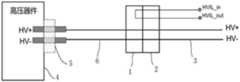
如图1所示,现有的高压器件80上集成有的高压互锁回路设计的形式一般为:高压器件内设有高压互锁回路的低压回路的信号输入线HVIL_in及信号输出线HVIL_out,并通过高压器件80上设有的低压接插头83连接至高压互锁回路的控制器84,其中,当连接有高压供电线的高压插头81插入高压器件的高压插口82时,高压插头81处的低压回路的开关等同闭合,此时高压器件80内的信号输入线HVIL_in及信号输出线HVIL_out两者连通,从而使得低压回路连通;而当高压插头81从高压器件80的高压插口82拔出时,高压器件80内的信号输入线HVIL_in及信号输出线HVIL_out两者不连通,从而使得低压回路断开。此外,当人员插拔高压插头81时,高压互锁回路的控制器84通过监测低压回路的通断,来触发高压互锁装置断开,从而引起整车下高压电,避免人员触电风险。As shown in FIG. 1 , the design of the high-voltage interlock loop integrated on the existing high-voltage device 80 is generally as follows: the signal input line HVIL_in and the signal output line HVIL_out of the low-voltage loop of the high-voltage interlock loop are provided in the high-voltage device, and the The low-
由于为了提高高压器件的高压安全防护性能,现有的高压器件需要通过重新设计才能带有高压互锁设计,无法沿用原型号的高压器件,而重新对高压器件进行高压互锁设计会增加高压器件的开发成本。In order to improve the high-voltage safety protection performance of high-voltage devices, the existing high-voltage devices need to be redesigned to have a high-voltage interlock design, and the original type of high-voltage devices cannot be used. development costs.
实用新型内容Utility model content
针对上述问题,本实用新型的目的在于提供一种高压互锁回路系统、用于高压互锁回路系统的母接件及公接件,其能够现有的需要对高压器件重新设计才能带有高压互锁设计的问题。In view of the above problems, the purpose of the present utility model is to provide a high-voltage interlocking circuit system, a female connector and a male connector for the high-voltage interlocking circuit system, which can be used to redesign high-voltage devices in order to carry high-voltage Interlocking design issues.
为了实现上述目的,第一方面的,本实用新型一实施例提供了一种用于高压互锁回路系统的母接件,用于与用于连接高压供电线的公接件配合,其包括:In order to achieve the above purpose, in the first aspect, an embodiment of the present utility model provides a female connector for a high-voltage interlock circuit system, which is used to cooperate with a male connector for connecting a high-voltage power supply line, which includes:
母接件主体;main body of female connector;
第一外接端子,设于所述母接件主体上,并用于与所述高压器件连接;a first external terminal, arranged on the main body of the female connector, and used for connecting with the high-voltage device;
第一接头,设于所述母接件主体上且与所述第一外接端子连接,并用于与所述公接件的接头配合;及,a first connector, arranged on the main body of the female connector and connected to the first external terminal, and used for mating with the connector of the male connector; and,
回路连通装置,设于所述母接件主体上,并用于在所述公接件与所述母接件两者配合好时,接通或断开所述高压互锁回路系统的低压回路;还用于在所述两者分开时,使所述低压回路的连通状态与配合好时的连通状态不同。a circuit communication device, arranged on the main body of the female connector, and used for connecting or disconnecting the low-voltage circuit of the high-voltage interlocking circuit system when the male connector and the female connector are well matched; It is also used to make the communication state of the low-pressure circuit different from the communication state of the low-pressure circuit when the two are separated.
作为上述方案的改进,所述回路连通装置包括:连通段、第一接触部及第二接触部;所述连通段连接于所述第一接触部与所述第二接触部之间;所述第一接触部与所述第二接触部在所述母接件主体上裸露设置,并用于在所述两者配合好时,与所述公接件上设有的用于连接低压回路的两个信号端的两个脚对应接触。As an improvement of the above solution, the circuit communication device includes: a communication segment, a first contact portion and a second contact portion; the communication segment is connected between the first contact portion and the second contact portion; the The first contact part and the second contact part are exposed on the main body of the female connector, and are used for connecting with the two connecting parts provided on the male connector for connecting the low-voltage circuit when the two are well matched. The two pins of each signal terminal are in corresponding contact.
作为上述方案的改进,所述第一外接端子为插头、插座、引脚或触点结构;所述第一接头为插头、插座、引脚或触点结构。As an improvement of the above solution, the first external terminal is a plug, a socket, a pin or a contact structure; the first connector is a plug, a socket, a pin or a contact structure.
第二方面的,本实用新型另一实施例提供了一种用于高压互锁回路系统的公接件,用于与第一方面的任一方案所述的母接件配合,其包括:In the second aspect, another embodiment of the present invention provides a male connector for a high-voltage interlock circuit system, which is used to cooperate with the female connector described in any one of the solutions of the first aspect, which includes:
公接件主体;The main body of the male connector;
第二外接端子,设于所述公接件主体上,并用于连接高压供电线;The second external terminal is arranged on the main body of the male connector and is used for connecting the high-voltage power supply line;
第二接头,设于所述公接件主体上且与所述第二外接端子连接,并用于与所述母接件的接头配合。The second connector is arranged on the main body of the male connector and is connected to the second external terminal, and is used for mating with the connector of the female connector.
作为上述方案的改进,所述公接件还包括:用于与所述低压回路的低压输入端连接的低压输入脚及用于与所述低压回路的低压输出端连接的低压输出脚;As an improvement of the above solution, the male connector further includes: a low-voltage input pin for connecting with the low-voltage input end of the low-voltage loop and a low-voltage output pin for connecting with the low-voltage output end of the low-voltage loop;
所述低压输入脚与所述低压输出脚该两脚均设于所述公接件主体上并裸露设置,且在所述公接件与所述母接件两者配合好时,该两脚通过与所述公接件上的回路连通装置相接触而连通。The low-voltage input pin and the low-voltage output pin are both disposed on the main body of the male connector and are exposed, and when the male connector and the female connector are well matched, the two pins It communicates through contact with the circuit communication means on the male connector.
作为上述方案的改进,所述第二外接端子为插头、插座、引脚或触点结构;所述第二接头为插头、插座、引脚或触点结构。As an improvement of the above solution, the second external terminal is a plug, a socket, a pin or a contact structure; the second connector is a plug, a socket, a pin or a contact structure.
第三方面的,本实用新型另一实施例提供了一种用于高压互锁回路系统的母接件,用于与用于连接高压器件的公接件配合,其,包括:In the third aspect, another embodiment of the present invention provides a female connector for a high-voltage interlock circuit system, which is used to cooperate with a male connector for connecting high-voltage devices, which includes:
母接件主体;main body of female connector;
第一外接端子,设于所述母接件主体上,并用于与高压供电线连接;The first external terminal is arranged on the main body of the female connector and is used for connecting with the high-voltage power supply line;
第一接头,设于所述母接件主体上且与所述第一外接端子连接,并用于与所述公接件的接头配合;及,a first connector, arranged on the main body of the female connector and connected to the first external terminal, and used for mating with the connector of the male connector; and,
回路连通装置,设于所述母接件主体上,并用于在所述公接件与所述母接件两者配合好时,接通或断开所述高压互锁回路系统的低压回路;还用于在所述两者分开时,使所述低压回路的连通状态与配合好时的连通状态不同。a circuit communication device, arranged on the main body of the female connector, and used for connecting or disconnecting the low-voltage circuit of the high-voltage interlocking circuit system when the male connector and the female connector are well matched; It is also used to make the communication state of the low-pressure circuit different from the communication state of the low-pressure circuit when the two are separated.
第四方面的,本实用新型另一实施例提供了一种用于高压互锁回路系统的公接件,用于与第三方面的方案的所述的母接件配合,其包括:In the fourth aspect, another embodiment of the present utility model provides a male connector for a high-voltage interlock circuit system, which is used to cooperate with the female connector of the solution of the third aspect, which includes:
公接件主体;The main body of the male connector;
第二外接端子,设于所述公接件主体上,并用于连接高压器件;The second external terminal is arranged on the main body of the male connector and is used to connect the high-voltage device;
第二接头,设于所述公接件主体上且与所述第二外接端子连接,并用于与所述母接件的接头配合。The second connector is arranged on the main body of the male connector and is connected to the second external terminal, and is used for mating with the connector of the female connector.
第五方面的,本实用新型另一实施例提供了一种高压互锁回路系统,其包括:高压器件、高压供电线、第一方面的任一方案所述的母接件及第二方面的任一方案所述的公接件:In the fifth aspect, another embodiment of the present invention provides a high-voltage interlock loop system, which includes: a high-voltage device, a high-voltage power supply line, the female connector according to any one of the first aspect, and the second aspect. The male connector described in either scheme:
所述高压器件的高压端口与所述第一外接端子连接,所述第二外接端子与所述高压供电线连接。The high-voltage port of the high-voltage device is connected to the first external terminal, and the second external terminal is connected to the high-voltage power supply line.
作为上述方案的改进,所述的高压互锁回路系统还包括:高压接插头;所述高压接插头的插头端与所述高压器件的高压端口固定连接,所述高压接插头的接线端通过连接线与所述第一外接端子连接。As an improvement of the above solution, the high-voltage interlock loop system further includes: a high-voltage connector; the plug end of the high-voltage connector is fixedly connected to the high-voltage port of the high-voltage device, and the terminal of the high-voltage connector is connected by A wire is connected to the first external terminal.
第六方面的,本实用新型另一实施例提供了一种高压互锁回路系统,其包括:高压器件、高压供电线、第三方面的方案的所述的母接件及第四方面的方案的所述的公接件;In the sixth aspect, another embodiment of the present invention provides a high-voltage interlocking loop system, which includes: a high-voltage device, a high-voltage power supply line, the female connector of the solution of the third aspect, and the solution of the fourth aspect the said male connector;
所述高压器件的高压端口与所述第二外接端子连接,所述第一外接端子与所述高压供电线连接。The high-voltage port of the high-voltage device is connected to the second external terminal, and the first external terminal is connected to the high-voltage power supply line.
作为上述方案的改进,所述的高压互锁回路系统还包括:高压接插头;所述高压接插头的插头端与所述高压器件的高压端口固定连接,所述高压接插头的接线端通过连接线与所述第二外接端子连接。As an improvement of the above solution, the high-voltage interlock loop system further includes: a high-voltage connector; the plug end of the high-voltage connector is fixedly connected to the high-voltage port of the high-voltage device, and the terminal of the high-voltage connector is connected by A wire is connected to the second external terminal.
相比于现有技术,采用本实用新型实施例提供的所述高压互锁回路系统、用于高压互锁回路系统的母接件、公接件及转接组件,无需对高压器件本身重新进行高压互锁设计,只需增加一对设有高压互锁设计的转接件,这一对转接件分别连接高压器件及高压供电线,当这一对转接件配合连接好时,便能够连通高压供电线及高压器件两者。由此可见,通过增加一对设有高压互锁设计的转接件,便可使不带有高压互锁设计的高压器件也可以实现高压互锁功能,提高了高压器件的高压安全防护性。Compared with the prior art, using the high-voltage interlocking circuit system, the female connector, the male connector and the adapter assembly for the high-voltage interlocking circuit system provided by the embodiment of the present utility model does not need to redo the high-voltage device itself. High-voltage interlock design, only need to add a pair of adapters with high-voltage interlock design. This pair of adapters is connected to the high-voltage device and the high-voltage power supply line respectively. Connect the high-voltage power supply line and the high-voltage device. It can be seen that by adding a pair of adapters with a high-voltage interlock design, a high-voltage device without a high-voltage interlock design can also realize the high-voltage interlock function, which improves the high-voltage safety protection of the high-voltage device.
附图说明Description of drawings
为了更清楚地说明本实用新型的技术方案,下面将对实施方式中所需要使用的附图作简单地介绍,显而易见地,下面描述中的附图仅仅是本实用新型的一些实施方式,对于本领域普通技术人员来讲,在不付出创造性劳动的前提下,还可以根据这些附图获得其他的附图。In order to illustrate the technical solutions of the present invention more clearly, the following briefly introduces the accompanying drawings used in the implementation manner. Obviously, the accompanying drawings in the following description are only some implementations of the present utility model. For those of ordinary skill in the art, other drawings can also be obtained from these drawings without any creative effort.
图1是现有技术的高压互锁回路系统的结构示意图;1 is a schematic structural diagram of a high-voltage interlock loop system in the prior art;
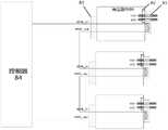
图2是本实用新型一实施例提供的一种高压互锁回路系统在低压回路断开状态下的示意图;2 is a schematic diagram of a high-voltage interlock circuit system provided in an embodiment of the present invention when the low-voltage circuit is disconnected;
图3是本实用新型一实施例提供的一种高压互锁回路系统在低压回路连通状态下的示意图。FIG. 3 is a schematic diagram of a high-voltage interlocking circuit system provided in an embodiment of the present invention in a connected state of a low-voltage circuit.
附图标注说明:Description of the attached drawings:
1.母接件;10.母接件主体;11.第一外接端子;12.第一接头;13.回路连通装置;130.连通段;131.第一接触部;132.第二接触部;1. Female connector; 10. Female connector body; 11. First external terminal; 12. First connector; 13. Circuit communication device; 130. Communication section; 131. First contact part; ;
2.公接件;20.公接件主体;21.第二外接端子;22.第二接头;23.低压输入脚;24.低压输出脚;2. Male connector; 20. Male connector body; 21. Second external terminal; 22. Second connector; 23. Low voltage input pin; 24. Low voltage output pin;
3.高压供电线;3. High voltage power supply line;
4.高压器件;40.高压端口;4. High voltage device; 40. High voltage port;
5.高压接插头;5. High voltage plug;
6.连接线。6. Connect the wires.
具体实施方式Detailed ways
下面将结合本实用新型实施例中的附图,对本实用新型实施例中的技术方案进行清楚、完整地描述,显然,所描述的实施例仅仅是本实用新型一部分实施例,而不是全部的实施例。基于本实用新型中的实施例,本领域普通技术人员在没有做出创造性劳动前提下所获得的所有其他实施例,都属于本实用新型保护的范围。The technical solutions in the embodiments of the present utility model will be clearly and completely described below with reference to the accompanying drawings in the embodiments of the present utility model. Obviously, the described embodiments are only a part of the embodiments of the present utility model, rather than all the implementations. example. Based on the embodiments of the present invention, all other embodiments obtained by those of ordinary skill in the art without creative work fall within the protection scope of the present invention.
在说明书和权利要求书的描述中,需要理解的是,术语“上”、“下”、“内”、“外”等指示的方位或位置关系为基于附图所示的方位或位置关系,仅是为了便于描述本实用新型实施例,而不是指示或暗示所指的装置或部件必须具有特定的方位、以特定的方位构造和操作,因此不能理解为对本实用新型实施例的限制。In the description of the specification and the claims, it should be understood that the orientation or positional relationship indicated by the terms "upper", "lower", "inner", "outer", etc. is based on the orientation or positional relationship shown in the accompanying drawings, It is only for the convenience of describing the embodiments of the present invention, rather than indicating or implying that the devices or components referred to must have a specific orientation, be constructed and operate in a specific orientation, and therefore should not be construed as a limitation on the embodiments of the present invention.
此外,在说明书和权利要求书中的术语第一、第二等仅用于区别相同技术特征的描述目的,而不能理解为指示或暗示相对重要性或者隐含指明所指示的技术特征的数量,也不一定描述次序或时间顺序。在合适的情况下术语是可以互换的。由此,限定有“第一”、“第二”的特征可以明示或者隐含地包括至少一个该特征。In addition, the terms first, second, etc. in the description and the claims are only used for the description purpose of distinguishing the same technical features, and cannot be understood as indicating or implying relative importance or implicitly indicating the number of the indicated technical features, Nor is an order or chronological order necessarily described. Terms are interchangeable under appropriate circumstances. Thus, a feature delimited with "first", "second" may expressly or implicitly include at least one of that feature.
参见图1与图2,本实用新型一实施例提供了一种高压互锁回路系统,其包括:高压器件4、高压供电线3及转接组件:所述转接组件包括公接件2及母接件1。所述母接件1包括:母接件主体10、第一外接端子11、第一接头12及回路连通装置13;所述第一外接端子11,设于所述母接件主体10上;所述第一接头12,设于所述母接件主体10上且与所述第一外接端子11连接;所述回路连通装置13,设于所述母接件主体10上,并用于在所述公接件2与所述母接件1两者配合好时,接通或断开所述高压互锁回路系统的低压回路;还用于在所述两者分开时,使所述低压回路的连通状态与配合好时的连通状态不同。所述公接件2包括:公接件主体20、第二外接端子21及第二接头22;所述第二外接端子21,设于所述公接件主体20上;所述第二接头22,设于所述公接件主体20上且与所述第二外接端子21连接;所述高压器件4的高压端口40(可以是接口、引脚或插座形式等)与所述第一外接端子11连接,所述第二外接端子21与所述高压供电线3连接。Referring to FIG. 1 and FIG. 2, an embodiment of the present invention provides a high-voltage interlock loop system, which includes: a high-
其中,当人员操作母接件1的第一接头12与公接件2的第二接头22配合连接时,便能够连通高压供电线3(可以是连接至高压电源的供电线)及高压器件4两者,同时所述母接件1上的所述回路连通装置13还会使得所述低压回路连通。当人员操作母接件1的第一接头12与公接件2的第二接头22分开时,便会断开高压供电线3与高压器件4两者的连接,同时还会使得所述低压回路断开。这样高压互锁回路系统的控制器通过识别低压回路的通断,来识别所述母接件1与所述公接件2的连接状态,进而在检测到所述母接件1与所述公接件2两者在插拔时,采取措施让该高压器件4的高压工作回路脱离高压状态(例如停止向该工作回路供高压电),从而避免人员触电风险。Wherein, when a person operates the
综上所述,采用本实施例,无需对高压器件4本身重新进行高压互锁设计,只需增加一对设有高压互锁设计的转接件,这一对转接件分别连接高压器件4及高压供电线3,当这一对转接件配合连接好时,便能够连通高压供电线3及高压器件4两者。由此可见,通过增加一对设有高压互锁设计的转接件,便可使不带有高压互锁设计的高压器件4也可以实现高压互锁功能,提高了高压器件4的高压安全防护性。To sum up, using this embodiment, it is not necessary to re-design the high-voltage interlock for the high-
可以理解的是,所述母接件1的所述第一外接端子11还可以是用于与高压供电线3连接,所述公接件2的所述第二外接端子21还可以是用于与高压器件4的高压端口40连接。It can be understood that the first
需要说明的是,所述第一外接端子11或所述第二外接端子21可以直接与所述高压器件4的高压端口40连接,也可以是通过连接线等方式来间接与所述高压器件4的高压端口40连接,在此不做具体限定。It should be noted that the first
在本实施例中,所述第一外接端子11与所述第二外接端子21两者,可以为插头、插座、引脚或触点等结构,在此不做具体限定。所述第一接头12与所述第二接头22两者,也可以为插头、插座、引脚或触点等结构,只要能够让该两个接头良好配合即可,在此也不做具体限定。In the present embodiment, both the first
示例性的,参见图1,所述回路连通装置13包括:连通段130、第一接触部131及第二接触部132;所述连通段130连接于所述第一接触部131与所述第二接触部132之间,所述第一接触部131与所述第二接触部132在所述母接件主体10上裸露设置;而所述公接件2上设有用于与所述低压回路的低压输入端HVIL_in连接的低压输入脚23及用于与所述低压回路的低压输出端HVIL_out连接的低压输出脚24;所述低压输入脚23与所述低压输出脚24该两脚均设于所述公接件主体20上并裸露设置。其中,当所述公接件2与所述母接件1两者配合好时,所述第一接触部131与所述低压输入脚23接触,所述第二接触部132与所述低压输出脚24接触,从而让所述低压回路为连通状态。Exemplarily, referring to FIG. 1 , the
可以理解的是,连通上述两个脚的所述回路连通装置13,还可以是一块裸露在所述母接件主体10上的导电块(图未示),或者是设有两个供所述低压输入脚23与所述低压输出脚24对应插接的插槽的导电体(图未示)等,在此不做具体限定。It can be understood that, the
需要说明的是,所述回路连通装置13连通或断开所述低压回路的方式还可以有:所述回路连通装置13包括一个接近检测传感器(图未示)、开关(图未示)及控制装置(图未示),当接近检测传感器检测到所述公接件2接近所述母接件1时,控制装置控制设于所述低压回路中的所述开关闭合,从而让所述低压回路连通,当接近检测传感器检测到所述公接件2与所述母接件1两者分离时,控制装置控制设于所述低压回路中的所述开关断开。或者,所述回路连通装置13包括一个具有弹性复位功能的开关按钮(图未示),该开关按钮设于所述低压回路中并裸露在所述母接件主体10上,当所述公接件2与所述母接件1配合接触时,所述开关按钮会被所述公接件2接触按下,从而使得低压回路连通;当所述公接件2与所述母接件1两者分开时,所述开关按钮由于失去外力的按压而会复位,从而使得低压回路断开。以上仅是回路连通装置13的其中一些示例结构,仅是为了便于理解而提出,不应以上述的具体结构来限定所述回路连通装置13的解释范围。It should be noted that, the
作为上述方案的改进,参见图1,所述的高压互锁回路系统,还包括:高压接插头5。其中,当所述母接件1用于连接高压器件4时,所述高压接插头5的插头端与所述高压器件4的高压端口40固定连接,所述高压接插头5的接线端通过连接线6与所述第一外接端子11连接。而当所述公接件2用于连接高压器件4时,所述高压接插头5的插头端与所述高压器件4的高压端口40固定连接,所述高压接插头5的接线端通过连接线6与所述第二外接端子21连接。As an improvement of the above solution, referring to FIG. 1 , the high-voltage interlocking circuit system further includes: a high-
可以理解的是,所述高压接插头5的插头端与所述高压器件4的高压端口40固定连接的方式可以为:胶水粘接固定或者是焊接固定等,在此不做具体限定。It can be understood that the way in which the plug end of the high
以上所述,仅为本实用新型的具体实施方式,但本实用新型的保护范围并不局限于此,任何熟悉本领域技术的技术人员在本实用新型公开的技术范围内,可轻易想到的变化或替换,都应涵盖在本实用新型的保护范围之内。因此,本实用新型的保护范围应以所述权利要求的保护范围为准。The above are only specific embodiments of the present utility model, but the protection scope of the present utility model is not limited to this. Any person skilled in the art can easily think of changes within the technical scope disclosed by the present utility model. Or replacement should be covered within the protection scope of the present invention. Therefore, the protection scope of the present invention should be based on the protection scope of the claims.
Claims (10)
Priority Applications (1)
| Application Number | Priority Date | Filing Date | Title |
|---|---|---|---|
| CN201922116186.8UCN211404911U (en) | 2019-11-28 | 2019-11-28 | High-voltage interlocking loop system, female connector and male connector for high-voltage interlocking loop system |
Applications Claiming Priority (1)
| Application Number | Priority Date | Filing Date | Title |
|---|---|---|---|
| CN201922116186.8UCN211404911U (en) | 2019-11-28 | 2019-11-28 | High-voltage interlocking loop system, female connector and male connector for high-voltage interlocking loop system |
Publications (1)
| Publication Number | Publication Date |
|---|---|
| CN211404911Utrue CN211404911U (en) | 2020-09-01 |
Family
ID=72212371
Family Applications (1)
| Application Number | Title | Priority Date | Filing Date |
|---|---|---|---|
| CN201922116186.8UActiveCN211404911U (en) | 2019-11-28 | 2019-11-28 | High-voltage interlocking loop system, female connector and male connector for high-voltage interlocking loop system |
Country Status (1)
| Country | Link |
|---|---|
| CN (1) | CN211404911U (en) |
- 2019
- 2019-11-28CNCN201922116186.8Upatent/CN211404911U/enactiveActive
Similar Documents
| Publication | Publication Date | Title |
|---|---|---|
| CN102738614A (en) | Connector and power management system thereof | |
| CN205985599U (en) | Prevent cable of opening a way | |
| CN208656083U (en) | electrical connector | |
| CN102646882A (en) | A USB2.0 connector socket and a plug used in conjunction with it | |
| AU2010229819B2 (en) | Electrical coupler system and method for manufacture thereof | |
| CN211404911U (en) | High-voltage interlocking loop system, female connector and male connector for high-voltage interlocking loop system | |
| CN104991092B (en) | Second protection testing terminal arranges adapter | |
| CN102646881B (en) | A USB3.0 connector socket and a plug used in conjunction with it | |
| CN201126892Y (en) | Explosion-proof inserted apparatus | |
| CN110198861B (en) | Electrical connection device, electrical architecture, and electric or hybrid electric vehicle | |
| CN205900999U (en) | A kind of anti-open circuit connector | |
| TWM583645U (en) | International charger structure | |
| CN206271988U (en) | Connector socket and plug | |
| CN115764463A (en) | Car Charging Adapter | |
| CN210692966U (en) | type-C power cables, head-mounted display devices and virtual reality systems | |
| CN211364270U (en) | High-voltage interlock device, high-voltage interlock circuit system and vehicle | |
| CN208955368U (en) | A kind of patchcord for switchgear aviation plug loop-around test | |
| CN206595486U (en) | Instrument terminal connector is protected in a kind of cyclization | |
| CN220544294U (en) | Connector for solving hot-line plugging | |
| CN217063310U (en) | From portable power source who takes charging wire | |
| CN215732586U (en) | DC power supply switching device | |
| CN221687912U (en) | Power adapter | |
| CN213026814U (en) | Multifunctional data connecting line | |
| CN203839660U (en) | Power Adapter with Reduced Mating and Unplugging Stress | |
| CN101989717B (en) | Socket and circuit board with the socket |
Legal Events
| Date | Code | Title | Description |
|---|---|---|---|
| GR01 | Patent grant | ||
| GR01 | Patent grant | ||
| TR01 | Transfer of patent right | Effective date of registration:20220105 Address after:511434 No. 36, Longying Road, Shilou Town, Panyu District, Guangzhou City, Guangdong Province Patentee after:GAC AION New Energy Vehicle Co.,Ltd. Address before:510030 23 building, Cheng Yue mansion 448-458, Dongfeng Middle Road, Yuexiu District, Guangzhou, Guangdong. Patentee before:GUANGZHOU AUTOMOBILE GROUP Co.,Ltd. | |
| TR01 | Transfer of patent right | ||
| CP03 | Change of name, title or address | Address after:No. 36 Longying Road, Shilou Town, Panyu District, Guangzhou City, Guangdong Province Patentee after:GAC AION NEW ENERGY AUTOMOBILE Co.,Ltd. Country or region after:China Address before:No. 36 Longying Road, Shilou Town, Panyu District, Guangzhou City, Guangdong Province Patentee before:GAC AION New Energy Vehicle Co.,Ltd. Country or region before:China | |
| CP03 | Change of name, title or address |