CN211402913U - Ultra-small zoom lens - Google Patents
Ultra-small zoom lensDownload PDFInfo
- Publication number
- CN211402913U CN211402913UCN202020261695.XUCN202020261695UCN211402913UCN 211402913 UCN211402913 UCN 211402913UCN 202020261695 UCN202020261695 UCN 202020261695UCN 211402913 UCN211402913 UCN 211402913U
- Authority
- CN
- China
- Prior art keywords
- lens
- image
- convex
- surface facing
- focal length
- Prior art date
- Legal status (The legal status is an assumption and is not a legal conclusion. Google has not performed a legal analysis and makes no representation as to the accuracy of the status listed.)
- Active
Links
Images


Landscapes
- Lenses (AREA)
Abstract
Translated fromChinese
Description
Translated fromChinese技术领域technical field
本实用新型属于安防监控技术领域,具体地涉及一种超小变焦镜头。The utility model belongs to the technical field of security monitoring, in particular to an ultra-small zoom lens.
背景技术Background technique
监控摄像机得到越来越多的应用,并逐渐提出24小时连续监控、低照度环境下监控、大视野监控等需求,进而又提升到要求监控影像高清化的趋势。Surveillance cameras are getting more and more applications, and gradually put forward the requirements of 24-hour continuous monitoring, monitoring in low-light environment, large-view monitoring, etc., and then increase to the trend of requiring high-definition monitoring images.
在需要实施24小时连续监控的工厂厂区、大厦、停车场中,小型且高画质的日夜两用摄像机的需求愈来愈旺。日夜两用摄像机的优势是即使在低照度,甚至没有可见光照明的环境中,运用夜间模式(夜间为黑白图像),使用近红外灯照射监控对象,也可以观察到清晰的图像。同时,不仅仅是观察监控对象,对监控对象的识别也成为了可能。In factories, buildings, and parking lots that require 24-hour continuous monitoring, there is a growing demand for small, high-quality day and night cameras. The advantage of day and night cameras is that even in environments with low illumination or even no visible light, clear images can be observed by using night mode (black and white images at night) and using near-infrared lights to illuminate the monitored object. At the same time, it is not only possible to observe the monitored objects, but also to identify the monitored objects.
如果将普通的日用型镜头安装在日夜两用摄像机上使用,在运用夜间模式时,由于纵向色差的影响,聚焦会产生偏焦,无法采集到清晰的图像。为了不产生偏焦,使镜头能够运用于日夜两用型摄像机,需要从可见光区域到近红外光线区域的范围内尽量减少纵向色差。If an ordinary day-use lens is installed on a day/night camera, when using night mode, due to the influence of longitudinal chromatic aberration, the focus will be out of focus, and a clear image cannot be captured. In order not to produce out-of-focus and enable the lens to be used in day and night cameras, it is necessary to minimize longitudinal chromatic aberration in the range from the visible light region to the near-infrared light region.
目前市面上的光学监控镜头存在的明显缺陷在于,光学镜头总长(TTL)过大,镜片过多,使得镜头整体成本过高、体积过大,影响使用;对传递函数管控不好,分辨率低,低解析,图像锐度差,图像不均匀;焦距段跨度小,视场角跨度小,切换灵活性差;红外共焦性不好,在切换可见红外的时候离焦量大,红外使用时像质差;以及变倍数低,涵盖焦距段不完善,实用性不高。The obvious defects of the current optical monitoring lenses on the market are that the total length of the optical lens (TTL) is too large and the number of lenses is too large, which makes the overall cost of the lens too high, the volume is too large, and affects the use; the transfer function is not well controlled and the resolution is low. , low resolution, poor image sharpness, uneven image; small span of focal length, small span of field of view, poor switching flexibility; poor infrared confocality, large amount of defocus when switching visible infrared, and the image when infrared is used The quality is poor; and the zoom factor is low, the coverage of the focal length is not perfect, and the practicability is not high.
为此,本实用新型提供了一种新的日夜两用的超小变焦监控镜头。To this end, the utility model provides a new ultra-small zoom monitoring lens for both day and night.
实用新型内容Utility model content
为了改进现有的监控镜头,本实用新型提供了一种超小变焦镜头,由物侧至像侧依序包括第一透镜、第二透镜、第三透镜、第四透镜、光阑、第五透镜、第六透镜、第七透镜、第八透镜和第九透镜;In order to improve the existing monitoring lens, the utility model provides an ultra-small zoom lens, which sequentially includes a first lens, a second lens, a third lens, a fourth lens, a diaphragm, a fifth lens from the object side to the image side lens, sixth lens, seventh lens, eighth lens and ninth lens;
该第一透镜具负屈光率,具有一朝向物侧的物侧面及一朝向像侧的像侧面,该物侧面为凸面,该像侧面为凹面;The first lens has a negative refractive index, has an object side facing the object side and an image side facing the image side, the object side is convex, and the image side is concave;
该第二透镜具负屈光率,具有一朝向物侧的物侧面及一朝向像侧的像侧面,该物侧面为凹面,该像侧面为凹面;The second lens has a negative refractive index, has an object side facing the object side and an image side facing the image side, the object side is concave, and the image side is concave;
该第三透镜具负屈光率,具有一朝向物侧的物侧面及一朝向像侧的像侧面,该物侧面具为凸面,该像侧面具为凹面;The third lens has a negative refractive index and has an object side facing the object side and an image side facing the image side, the object side has a convex surface, and the image side has a concave surface;
该第四透镜具正屈光率,具有一朝向物侧的物侧面及一朝向像侧的像侧面,该物侧面为凸面,该像侧面为凸面;The fourth lens has a positive refractive index and has an object side facing the object side and an image side facing the image side, the object side is convex, and the image side is convex;
该第五透镜具正屈光率,具有一朝向物侧的物侧面及一朝向像侧的像侧面,该物侧面为凸面,该像侧面为凹面;The fifth lens has a positive refractive index, has an object side facing the object side and an image side facing the image side, the object side is convex, and the image side is concave;
该第六透镜具正屈光率,具有一朝向物侧的物侧面及一朝向像侧的像侧面,该物侧面为凸面,该像侧面为凸面;The sixth lens has a positive refractive index, has an object side facing the object side and an image side facing the image side, the object side is convex, and the image side is convex;
该第七透镜具负屈光率,具有一朝向物侧的物侧面及一朝向像侧的像侧面,该物侧面为凹面,该像侧面为凹面;The seventh lens has a negative refractive index, has an object side facing the object side and an image side facing the image side, the object side is concave, and the image side is concave;
该第八透镜具正屈光率,具有一朝向物侧的物侧面及一朝向像侧的像侧面,该物侧面为凸面,该像侧面为凸面;The eighth lens has a positive refractive index and has an object side facing the object side and an image side facing the image side, the object side is convex, and the image side is convex;
该第九透镜具负屈光率,具有一朝向物侧的物侧面及一朝向像侧的像侧面,该物侧面为凹面,该像侧面为凸面。The ninth lens has a negative refractive index and has an object side facing the object side and an image side facing the image side. The object side surface is concave and the image side surface is convex.
第一至第四透镜构成调焦透镜组;第五至第九构成变倍透镜组。The first to fourth lenses constitute a focusing lens group; the fifth to ninth lenses constitute a variable magnification lens group.
该超小变焦镜头具有屈光率的透镜只有上述九片。This ultra-small zoom lens has only the above-mentioned nine lenses.
优选地,该超小变焦镜头还满足:该该第三透镜与第四透镜相互胶合。Preferably, the ultra-small zoom lens also satisfies that: the third lens and the fourth lens are cemented with each other.
优选地,该超小变焦镜头还满足:该该第六透镜与第七透镜相互胶合。Preferably, the ultra-small zoom lens also satisfies that: the sixth lens and the seventh lens are cemented with each other.
优选地,该超小变焦镜头还满足:|vd4-vd3|>30,其中,vd3和vd4分别为第三透镜、第四透镜的色散系数。Preferably, the ultra-small zoom lens also satisfies: |vd4-vd3|>30, where vd3 and vd4 are the dispersion coefficients of the third lens and the fourth lens, respectively.
优选地,该超小变焦镜头还满足:|vd7-vd6|>30,其中,vd6和vd7分别为第六透镜、第七透镜的色散系数。Preferably, the ultra-small zoom lens also satisfies: |vd7-vd6|>30, wherein vd6 and vd7 are the dispersion coefficients of the sixth lens and the seventh lens, respectively.
优选地,该超小变焦镜头还满足:第三透镜、第九透镜为16阶偶次塑料非球面设计。Preferably, the ultra-small zoom lens also satisfies that: the third lens and the ninth lens are 16th-order even-order plastic aspherical designs.
优选地,该超小变焦镜头还满足:第一透镜和第七透镜均采用高折射率材料,nd1=1.835,nd7=1.847,其中nd1是第一透镜的折射率,nd7是第七透镜的折射率。Preferably, the ultra-small zoom lens also satisfies that: both the first lens and the seventh lens are made of high refractive index materials, nd1=1.835, nd7=1.847, where nd1 is the refractive index of the first lens, and nd7 is the refractive index of the seventh lens Rate.
优选地,该超小变焦镜头还满足:第二透镜、第三透镜和第六透镜均使用色散系数较大的材料,其中vd2=58.35,vd3=59.51,vd6=51.16,vd2、vd3和vd6分别是第二透镜、第三透镜和第六透镜的色散系数。Preferably, the ultra-small zoom lens also satisfies: the second lens, the third lens and the sixth lens are all made of materials with large dispersion coefficients, wherein vd2=58.35, vd3=59.51, vd6=51.16, vd2, vd3 and vd6 respectively is the dispersion coefficient of the second lens, the third lens and the sixth lens.
本实用新型的有益效果在于:The beneficial effects of the present utility model are:
1.光学TTL小于33mm,且采用玻塑混合9片式设计,使镜头整体体积小,且制造成本低廉;1. The optical TTL is less than 33mm, and the glass-plastic hybrid 9-piece design makes the overall size of the lens small and the manufacturing cost low;
2.对传递函数管控好,高分辨率(2K),高解析,图像锐度高,图像均匀;2. Good control of transfer function, high resolution (2K), high resolution, high image sharpness and uniform image;
3.焦距段跨度大,视场角跨度大,切换灵活性强;3. The focal length span is large, the field of view span is large, and the switching flexibility is strong;
4.使用切换片进行可见-红外切换,提高红外成像质量。4. Use the switching sheet to perform visible-infrared switching to improve the quality of infrared imaging.
附图说明Description of drawings
为了更清楚地说明本实用新型实施例中的技术方案,下面将对实施例描述中所需要使用的附图作简要介绍,显而易见地,下面描述中的附图仅仅是本实用新型的一些实施例,对于本领域的普通技术人员来讲,在不付出创造性劳动的前提下,还可以根据这些附图获得其他的附图。In order to illustrate the technical solutions in the embodiments of the present invention more clearly, the following briefly introduces the accompanying drawings used in the description of the embodiments. Obviously, the drawings in the following description are only some embodiments of the present invention. , for those of ordinary skill in the art, other drawings can also be obtained from these drawings without any creative effort.
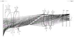
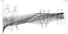
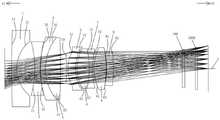
图1为本实用新型实施例一的处于最短焦距时的结构示意图;1 is a schematic structural diagram of Embodiment 1 of the present utility model when it is at the shortest focal length;
图2为本实用新型实施例一的处于最长焦距时的结构示意图;2 is a schematic structural diagram of Embodiment 1 of the present utility model at the longest focal length;
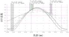
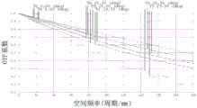
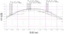
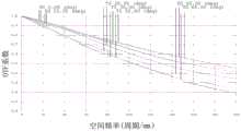
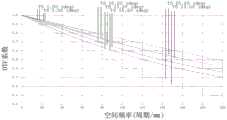
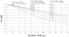
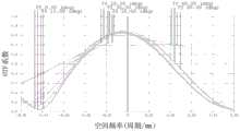
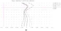
图3为本实用新型实施例一的处于最短焦距时的可见光0.450-0.650μm的MTF图;Fig. 3 is the MTF diagram of visible light 0.450-0.650 μm at the shortest focal length according to the first embodiment of the present invention;
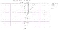
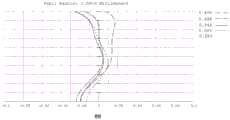
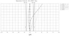
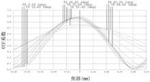
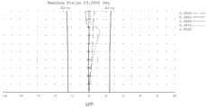
图4为本实用新型实施例一的处于最短焦距时的可见光0.450-0.650μm的离焦曲线图;4 is a defocus curve diagram of visible light 0.450-0.650 μm at the shortest focal length according to Embodiment 1 of the present invention;
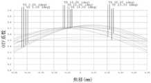
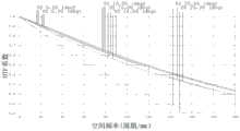
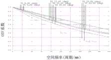
图5为本实用新型实施例一的处于最短焦距时的红外850nm的MTF图;Fig. 5 is the MTF diagram of infrared 850nm at the shortest focal length according to the first embodiment of the present utility model;
图6为本实用新型实施例一的处于最短焦距时的红外线850nm的离焦曲线图;6 is a defocusing curve diagram of infrared rays at 850 nm at the shortest focal length according to Embodiment 1 of the present utility model;
图7为本实用新型实施例一的处于最短焦距时的横向色差曲线图;7 is a lateral chromatic aberration curve diagram at the shortest focal length according to Embodiment 1 of the present utility model;
图8为本实用新型实施例一的处于最短焦距时的纵向像差图示意图;8 is a schematic diagram of a longitudinal aberration diagram at the shortest focal length according to Embodiment 1 of the present invention;
图9为本实用新型实施例一的处于最长焦距时的可见光0.450-0.650μm的MTF图;9 is the MTF diagram of the visible light 0.450-0.650 μm at the longest focal length according to the first embodiment of the present invention;
图10为本实用新型实施例一的处于最长焦距时的可见光0.450-0.650μm的离焦曲线图;10 is a defocus curve diagram of visible light 0.450-0.650 μm at the longest focal length according to Embodiment 1 of the present invention;
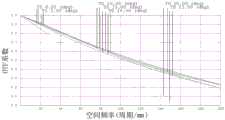
图11为本实用新型实施例一的处于最长焦距时的红外850nm的MTF图;11 is the MTF diagram of the infrared 850nm at the longest focal length according to the first embodiment of the present invention;
图12为本实用新型实施例一的处于最长焦距时的红外线850nm的离焦曲线图;12 is a defocus curve diagram of infrared rays at 850 nm at the longest focal length according to Embodiment 1 of the present invention;
图13为本实用新型实施例一的处于最长焦距时的横向色差曲线图;13 is a lateral chromatic aberration curve diagram at the longest focal length according to Embodiment 1 of the present invention;
图14为本实用新型实施例一的处于最长焦距时的纵向像差图示意图;14 is a schematic diagram of a longitudinal aberration diagram at the longest focal length according to Embodiment 1 of the present invention;
图15为本实用新型实施例二的处于最短焦距时的结构示意图;15 is a schematic structural diagram of the second embodiment of the present invention when it is at the shortest focal length;
图16为本实用新型实施例二的处于最长焦距时的结构示意图;16 is a schematic structural diagram of the second embodiment of the present invention when it is at the longest focal length;
图17为本实用新型实施例二的处于最短焦距时的可见光0.450-0.650μm的MTF图;17 is the MTF diagram of visible light 0.450-0.650 μm at the shortest focal length according to the second embodiment of the present invention;
图18为本实用新型实施例二的处于最短焦距时的可见光0.450-0.650μm的离焦曲线图;18 is a defocus curve diagram of visible light 0.450-0.650 μm at the shortest focal length according to the second embodiment of the present invention;
图19为本实用新型实施例二的处于最短焦距时的红外850nm的MTF图;19 is the MTF diagram of the infrared 850nm at the shortest focal length according to the second embodiment of the present invention;
图20为本实用新型实施例二的处于最短焦距时的红外线850nm的离焦曲线图;Fig. 20 is the defocus curve diagram of infrared ray 850nm when being at the shortest focal length according to the second embodiment of the present utility model;
图21为本实用新型实施例二的处于最短焦距时的横向色差曲线图;21 is a lateral chromatic aberration curve diagram at the shortest focal length according to
图22为本实用新型实施例二的处于最短焦距时的纵向像差图示意图;22 is a schematic diagram of a longitudinal aberration diagram at the shortest focal length according to
图23为本实用新型实施例二的处于最长焦距时的可见光0.450-0.656μm的MTF图;23 is the MTF diagram of visible light 0.450-0.656 μm at the longest focal length according to the second embodiment of the present invention;
图24为本实用新型实施例二的处于最长焦距时的可见光0.450-0.656μm的离焦曲线图;24 is a defocus curve diagram of visible light 0.450-0.656 μm at the longest focal length according to the second embodiment of the present invention;
图25为本实用新型实施例二的处于最长焦距时的红外850nm的MTF图;25 is the MTF diagram of the infrared 850nm at the longest focal length according to the second embodiment of the present invention;
图26为本实用新型实施例二的处于最长焦距时的红外线850nm的离焦曲线图;26 is a defocus curve diagram of infrared rays at 850 nm at the longest focal length according to the second embodiment of the present invention;
图27为本实用新型实施例二的处于最长焦距时的横向色差曲线图;27 is a lateral chromatic aberration curve diagram at the longest focal length according to the second embodiment of the present invention;
图28为本实用新型实施例二的处于最长焦距时的纵向像差图示意图;28 is a schematic diagram of a longitudinal aberration diagram at the longest focal length according to the second embodiment of the present invention;
图29为本实用新型实施例三的处于最短焦距时的结构示意图;29 is a schematic structural diagram of Embodiment 3 of the present invention when it is at the shortest focal length;
图30为本实用新型实施例三的处于最长焦距时的结构示意图;30 is a schematic structural diagram of Embodiment 3 of the present utility model when it is at the longest focal length;
图31为本实用新型实施例三的处于最短焦距时的可见光0.450-0.650μm的MTF图;31 is the MTF diagram of the visible light 0.450-0.650 μm at the shortest focal length according to the third embodiment of the present invention;
图32为本实用新型实施例三的处于最短焦距时的可见光0.450-0.650μm的离焦曲线图;32 is a defocus curve diagram of visible light 0.450-0.650 μm at the shortest focal length according to the third embodiment of the present invention;
图33为本实用新型实施例三的处于最短焦距时的红外850nm的MTF图;33 is the MTF diagram of the infrared 850nm at the shortest focal length according to the third embodiment of the present invention;
图34为本实用新型实施例三的处于最短焦距时的红外线850nm的离焦曲线图;34 is a defocus curve diagram of infrared rays at 850 nm at the shortest focal length according to Embodiment 3 of the present utility model;
图35为本实用新型实施例三的处于最短焦距时的横向色差曲线图;35 is a lateral chromatic aberration curve diagram at the shortest focal length according to Embodiment 3 of the present utility model;
图36为本实用新型实施例三的处于最短焦距时的纵向像差图示意图;36 is a schematic diagram of a longitudinal aberration diagram at the shortest focal length according to Embodiment 3 of the present invention;
图37为本实用新型实施例三的处于最长焦距时的可见光0.450-0.656μm的MTF图;37 is the MTF diagram of the visible light 0.450-0.656 μm at the longest focal length according to the third embodiment of the present invention;
图38为本实用新型实施例三的处于最长焦距时的可见光0.450-0.656μm的离焦曲线图;38 is a defocus curve diagram of visible light 0.450-0.656 μm at the longest focal length according to the third embodiment of the present invention;
图39为本实用新型实施例三的处于最长焦距时的红外850nm的MTF图;39 is the MTF diagram of the infrared 850nm at the longest focal length according to the third embodiment of the present invention;
图40为本实用新型实施例三的处于最长焦距时的红外线850nm的离焦曲线图;40 is a defocus curve diagram of infrared rays at 850 nm at the longest focal length according to the third embodiment of the present invention;
图41为本实用新型实施例三的处于最长焦距时的横向色差曲线图;41 is a lateral chromatic aberration curve diagram at the longest focal length according to Embodiment 3 of the present invention;
图42为本实用新型实施例三的处于最长焦距时的纵向像差图示意图;42 is a schematic diagram of a longitudinal aberration diagram at the longest focal length according to Embodiment 3 of the present invention;
图43为本实用新型实施例四的处于最短焦距时的结构示意图;43 is a schematic structural diagram of
图44为本实用新型实施例四的处于最长焦距时的结构示意图;44 is a schematic structural diagram of
图45为本实用新型实施例四的处于最短焦距时的可见光0.450-0.650μm的MTF图;45 is the MTF diagram of the visible light 0.450-0.650 μm at the shortest focal length according to the fourth embodiment of the present invention;
图46为本实用新型实施例四的处于最短焦距时的可见光0.450-0.650μm的离焦曲线图;46 is a defocus curve diagram of visible light 0.450-0.650 μm at the shortest focal length according to the fourth embodiment of the present invention;
图47为本实用新型实施例四的处于最短焦距时的红外850nm的MTF图;47 is the MTF diagram of the infrared 850nm at the shortest focal length according to the fourth embodiment of the present invention;
图48为本实用新型实施例四的处于最短焦距时的红外线850nm的离焦曲线图;48 is a defocus curve diagram of infrared rays at 850 nm at the shortest focal length according to
图49为本实用新型实施例四的处于最短焦距时的横向色差曲线图;49 is a lateral chromatic aberration curve diagram at the shortest focal length according to
图50为本实用新型实施例四的处于最短焦距时的纵向像差图示意图;50 is a schematic diagram of a longitudinal aberration diagram at the shortest focal length according to
图51为本实用新型实施例四的处于最长焦距时的可见光0.450-0.656μm的MTF图;51 is the MTF diagram of the visible light 0.450-0.656 μm at the longest focal length according to the fourth embodiment of the present invention;
图52为本实用新型实施例四的处于最长焦距时的可见光0.450-0.656μm的离焦曲线图;52 is a defocus curve diagram of visible light 0.450-0.656 μm at the longest focal length according to
图53为本实用新型实施例四的处于最长焦距时的红外850nm的MTF图;53 is the MTF diagram of the infrared 850nm at the longest focal length according to the fourth embodiment of the present invention;
图54为本实用新型实施例四的处于最长焦距时的红外线850nm的离焦曲线图;54 is a defocus curve diagram of infrared rays at 850 nm at the longest focal length according to
图55为本实用新型实施例四的处于最长焦距时的横向色差曲线图;55 is a lateral chromatic aberration curve diagram at the longest focal length according to
图56为本实用新型实施例四的处于最长焦距时的纵向像差图示意图。56 is a schematic diagram of a longitudinal aberration diagram at the longest focal length according to
具体实施方式Detailed ways
为进一步说明各实施例,本实用新型提供有附图。这些附图为本实用新型揭露内容的一部分,其主要用以说明实施例,并可配合说明书的相关描述来解释实施例的运作原理。配合参考这些内容,本领域普通技术人员应能理解其他可能的实施方式以及本实用新型的优点。图中的组件并未按比例绘制,而类似的组件符号通常用来表示类似的组件。To further illustrate the various embodiments, the present invention provides accompanying drawings. These drawings are a part of the disclosure of the present invention, which are mainly used to illustrate the embodiments, and can be combined with the relevant description of the specification to explain the operation principles of the embodiments. With reference to these contents, those of ordinary skill in the art should be able to understand other possible embodiments and the advantages of the present invention. Components in the figures are not drawn to scale, and similar component symbols are often used to represent similar components.
现结合附图和具体实施方式对本实用新型进一步说明。The present utility model will now be further described with reference to the accompanying drawings and specific embodiments.
所说的「一透镜具有正屈光率(或负屈光率)」,是指所述透镜以高斯光学理论计算出来的近轴屈光率为正(或为负)。所说的「透镜的物侧面(或像侧面)」定义为成像光线通过透镜表面的特定范围。透镜的面形凹凸判断可依该领域中通常知识者的判断方式,即通过曲率半径(简写为R值)的正负号来判断透镜面形的凹凸。R值可常见被使用于光学设计软件中,例如Zemax或CodeV。R值亦常见于光学设计软件的透镜资料表(lens data sheet)中。以物侧面来说,当R值为正时,判定为物侧面为凸面;当R值为负时,判定物侧面为凹面。反之,以像侧面来说,当R值为正时,判定像侧面为凹面;当R值为负时,判定像侧面为凸面。The "a lens has a positive refractive power (or a negative refractive power)" means that the paraxial refractive power of the lens calculated by the Gaussian optical theory is positive (or negative). The so-called "object side (or image side) of the lens" is defined as the specific range of the imaging light passing through the surface of the lens. The surface concavity and convexity of the lens can be judged according to the judgment method of ordinary knowledge in the field, that is, the convexity and concavity of the lens surface shape can be judged by the sign of the radius of curvature (abbreviated as R value). R-values are commonly used in optical design software such as Zemax or CodeV. R-values are also commonly found in lens data sheets of optical design software. For the side of the object, when the value of R is positive, it is determined that the side of the object is convex; when the value of R is negative, the side of the object is determined to be concave. Conversely, for the image side, when the R value is positive, the image side is determined to be concave; when the R value is negative, the image side is determined to be convex.
本实用新型提供了一种超小变焦镜头,由物侧至像侧依序包括第一透镜、第二透镜、第三透镜、第四透镜、光阑、第五透镜、第六透镜、第七透镜、第八透镜和第九透镜。The utility model provides an ultra-small zoom lens, which comprises a first lens, a second lens, a third lens, a fourth lens, a diaphragm, a fifth lens, a sixth lens and a seventh lens in sequence from the object side to the image side lens, an eighth lens, and a ninth lens.
该第一透镜具负屈光率,具有一朝向物侧的物侧面及一朝向像侧的像侧面,该物侧面具有一在圆周附近区域的凸面部,该像侧面具有一在光轴附近区域的凹面部。The first lens has a negative refractive index, has an object side facing the object side and an image side facing the image side, the object side has a convex portion near the circumference, and the image side has a region near the optical axis the concave face.
该第二透镜具负屈光率,具有一朝向物侧的物侧面及一朝向像侧的像侧面,该物侧面具有一在圆周附近区域的凹面部,该像侧面具有一在光轴附近区域的凹面部。The second lens has a negative refractive index, has an object side facing the object side and an image side facing the image side, the object side has a concave portion near the circumference, and the image side has a region near the optical axis the concave face.
该第三透镜具负屈光率,具有一朝向物侧的物侧面及一朝向像侧的像侧面,该物侧面具有一在圆周附近区域的凸面部,该像侧面具有一在光轴附近区域的凹面部。The third lens has a negative refractive index, has an object side facing the object side and an image side facing the image side, the object side has a convex portion near the circumference, and the image side has a region near the optical axis the concave face.
该第四透镜具正屈光率,具有一朝向物侧的物侧面及一朝向像侧的像侧面,该物侧面具有一在圆周附近区域的凸面部,该像侧面具有一在光轴附近区域的凹面部。The fourth lens has a positive refractive index, has an object side facing the object side and an image side facing the image side, the object side has a convex portion near the circumference, and the image side has a region near the optical axis the concave face.
该第五透镜具正屈光率,具有一朝向物侧的物侧面及一朝向像侧的像侧面,该物侧面具有一在圆周附近区域的凸面部,该像侧面具有一在光轴附近区域的凹面部。The fifth lens has a positive refractive index, has an object side facing the object side and an image side facing the image side, the object side has a convex portion near the circumference, and the image side has a region near the optical axis the concave face.
该第六透镜具正屈光率,具有一朝向物侧的物侧面及一朝向像侧的像侧面,该物侧面具有一在圆周附近区域的凸面部,该像侧面具有一在光轴附近区域的凸面部。The sixth lens has a positive refractive index, has an object side facing the object side and an image side facing the image side, the object side has a convex portion near the circumference, and the image side has a region near the optical axis convex face.
该第七透镜具负屈光率,具有一朝向物侧的物侧面及一朝向像侧的像侧面,该物侧面具有一在圆周附近区域的凹面部,该像侧面具有一在光轴附近区域的凹面部。The seventh lens has a negative refractive index, has an object side facing the object side and an image side facing the image side, the object side has a concave portion near the circumference, and the image side has a region near the optical axis the concave face.
该第八透镜具正屈光率,具有一朝向物侧的物侧面及一朝向像侧的像侧面,该物侧面具有一在圆周附近区域的凸面部,该像侧面具有一在光轴附近区域的凸面部。The eighth lens has a positive refractive index, has an object side facing the object side and an image side facing the image side, the object side has a convex portion near the circumference, and the image side has a region near the optical axis convex face.
该第九透镜具负屈光率,具有一朝向物侧的物侧面及一朝向像侧的像侧面,该物侧面具有一在圆周附近区域的凹面部,该像侧面具有一在光轴附近区域的凸面部。The ninth lens has a negative refractive index, has an object side facing the object side and an image side facing the image side, the object side has a concave portion near the circumference, and the image side has a region near the optical axis convex face.
第一至第四透镜构成调焦透镜组;第五至第九构成变倍透镜组。The first to fourth lenses constitute a focusing lens group; the fifth to ninth lenses constitute a variable magnification lens group.
本实用新型采用九片透镜,并通过对各个透镜的屈光率以及面型的排列设计,具有光学TTL小于33mm,镜头整体体积小,且制造成本低廉;对传递函数管控好,高分辨率(2K),高解析,图像锐度高,图像均匀;焦距段跨度大,视场角跨度大,切换灵活性强;使用切换片进行可见-红外切换,提高红外成像质量等优点,并且该设计采用二组元变焦设计,变焦过程像质稳定,且使结构设计简单,利于大规模量产。The utility model adopts nine lenses, and through the arrangement design of the refractive index and surface shape of each lens, the optical TTL is less than 33mm, the overall size of the lens is small, and the manufacturing cost is low; the transfer function is well controlled, and the high resolution ( 2K), high resolution, high image sharpness, uniform image; large span of focal length, large span of field of view, and strong switching flexibility; using switching film for visible-infrared switching to improve infrared imaging quality and other advantages, and the design adopts Two-component zoom design, stable image quality during zooming, and simple structure design, which is conducive to mass production.
优选地,该超小变焦镜头还满足:第三、第四透镜为胶合片,且|vd4-vd3|>30,其中,vd3和vd4分别为第三透镜、第四透镜的色散系数,有利于校正色差。Preferably, the ultra-small zoom lens also satisfies: the third and fourth lenses are plywood, and |vd4-vd3|>30, where vd3 and vd4 are the dispersion coefficients of the third lens and the fourth lens, respectively, which is beneficial to Correct chromatic aberration.
优选地,该超小变焦镜头还满足:第六、第七透镜为胶合片,且|vd7-vd6|>30,其中,vd6和vd7分别为第六透镜、第七透镜的色散系数,有利于校正色差。Preferably, the ultra-small zoom lens also satisfies: the sixth and seventh lenses are plywood, and |vd7-vd6|>30, where vd6 and vd7 are the dispersion coefficients of the sixth and seventh lenses, respectively, which is beneficial to Correct chromatic aberration.
优选地,该超小变焦镜头还满足:第三透镜、第九透镜为16阶偶次塑料非球面设计,于矫正二级光谱及高级像差,同时利于镜头结构设计,降低镜头成本。Preferably, the ultra-small zoom lens also satisfies that the third lens and the ninth lens are 16th-order even-order plastic aspherical designs, which can correct the secondary spectrum and advanced aberrations, facilitate the lens structure design, and reduce the cost of the lens.
优选地,该超小变焦镜头还满足:nd1=1.835,nd7=1.847,第一透镜和第七透镜均采用高折射率材料,能够比较好的优化光学结构。Preferably, the ultra-small zoom lens also satisfies: nd1=1.835, nd7=1.847, and both the first lens and the seventh lens are made of high refractive index materials, which can better optimize the optical structure.
优选地,该超小变焦镜头还满足:vd2=58.35,vd3=59.51,vd6=51.16,第二透镜、第三透镜和第六透镜均使用色散系数较大的材料,利于减小光的色散,优化色差。Preferably, the ultra-small zoom lens also satisfies: vd2=58.35, vd3=59.51, vd6=51.16, the second lens, the third lens and the sixth lens are all made of materials with larger dispersion coefficients, which is beneficial to reduce the dispersion of light, Optimize chromatic aberration.
优选地,该设计中的镜头使用可见-红外切换片设计,兼顾可见和红外的成像像质,提高总体成像质量。Preferably, the lens in this design uses a visible-infrared switching sheet design, taking into account the imaging quality of both visible and infrared, and improving the overall imaging quality.
下面将以具体实施例对本实用新型的变焦镜头进行详细说明。The zoom lens of the present invention will be described in detail below with specific embodiments.
实施一implement one
如图1和2所示,一种超小变焦镜头,从物侧A1至像侧A2沿一光轴I依次包括第一透镜1至第四透镜4、光阑10、第五透镜5至第九透镜9、保护玻璃100和成像面1000;该第一透镜1至第九透镜9各自包括一朝向物侧A1且使成像光线通过的物侧面以及一朝向像侧A2且使成像光线通过的像侧面。As shown in Figs. 1 and 2, an ultra-small zoom lens includes a first lens 1 to a
该第一透镜1具负屈光率,该第一透镜1的物侧面11为凸面,该第一透镜1的像侧面12为凹面;第二透镜2具负屈光率,该第二透镜2的物侧面21为凹面,该第二透镜2的像侧面22为凹面;该第三透镜3具负屈光率,该第三透镜3的物侧面31为凸面,该第三透镜3的像侧面32为凸面;该第四透镜4具正屈光率,该第四透镜4的物侧面41为凸面,该第四透镜4的像侧面42为凸面;该第一透镜1至第四透镜4构成调焦透镜组,可沿光轴I相对于光阑10来回移动。The first lens 1 has a negative refractive power, the
第五透镜5具正屈光率,该第五透镜5的物侧面51为凸面,该第五透镜5的像侧面52为凹面;第六透镜6具正屈光率,该第六透镜6的物侧面61为凸面,该第六透镜6的像侧面62为凸面;第七透镜7具负屈光率,该第七透镜7的物侧面71为凹面,该第七透镜7的像侧面72为凹面;第八透镜8具正屈光率,该第八透镜8的物侧面81为凸面,该第八透镜8的像侧面82为凸面;第九透镜9具负屈光率,该第九透镜9的物侧面91为凸面,该第九透镜9的像侧面92为凸面。该第五透镜5至第九透镜9构成变倍透镜组,可沿光轴I相对于光阑10来回移动。The
在本实施例中,使用七片玻璃和两片塑料非球面的组合,包含2组双胶合透镜,第一透镜1至第四透镜4为镜头的前组,第五透镜5至第九透镜9为镜头的后组,第三、第四透镜为胶合透镜,第六、第七透镜为胶合透镜,第五、第九透镜为塑料非球面透镜,其中光阑10位于第四透镜和第五透镜之间。In this embodiment, a combination of seven pieces of glass and two pieces of plastic aspheric surfaces is used, including two groups of doublet lenses, the first lens 1 to the
本具体实施例的最短焦距(广角)时的详细光学数据如表1-1所示。The detailed optical data at the shortest focal length (wide angle) of this specific embodiment are shown in Table 1-1.
表1-1实施例一的最短焦距时的详细光学数据Table 1-1 Detailed optical data at the shortest focal length of Example 1


本具体实施例的最长焦距(长焦)时的详细光学数据如表1-2所示。The detailed optical data at the longest focal length (telephoto) of this specific embodiment are shown in Table 1-2.
表1-2实施例一的最长焦距时的详细光学数据Table 1-2 Detailed optical data at the longest focal length of Example 1


本具体实施例中,物侧面31、91和像侧面32、92依下列非球面曲线公式定义:In this specific embodiment, the object sides 31, 91 and the image sides 32, 92 are defined according to the following aspheric curve formula:

其中:in:
z:非球面的深度(非球面上距离光轴为y的点,与相切于非球面光轴上顶点之切面,两者间的垂直距离);z: the depth of the aspheric surface (the point on the aspheric surface that is y away from the optical axis, and the tangent plane tangent to the vertex on the optical axis of the aspheric surface, the vertical distance between the two);
c:非球面顶点的曲率(the vertex curvature);c: the vertex curvature of the aspherical vertex;
K:锥面系数(Conic Constant);K: Conic Constant;

rn:归一化半径(normalization radius(NRADIUS));rn : normalization radius (NRADIUS);
u:r/rn;u: r/rn ;
am:第m阶Qcon系数(is the mth Qcon coefficient);am : the mth order Qcon coefficient (is the mth Qcon coefficient);
Qmcon:第m阶Qcon多项式(the mth Qcon polynomial)。Qmcon : the mth Qconpolynomial .
本实施例的解像力请参阅图3-14,具体地,参考图3和图5,从图上可以看出对传函管控好,分辨率低,低解析度,可见光环境下,在广角时,200lp/mm空间频率的MTF值低至0.25,在长焦时,200lp/mm空间频率的MTF值甚至低于0.1;在红外环境下,200lp/mm空间频率下,MTF值均大于0.18,拍摄噪点少;可见光与红外850nm共焦性请参阅图4和图6,可以看出可见光与红外共焦性好,广角下,可见与红外切换时的离焦量小于4μm,长焦下,可见与红外切换时的离焦量小于10μm;横向色差图详见图7和图13,可以看出横向色差小于±0.005mm;纵向像差图详见图8和图14,可以看出横轴色差小。For the resolution of this embodiment, please refer to Figures 3-14. Specifically, refer to Figures 3 and 5. It can be seen from the figures that the transmission is well controlled, the resolution is low, and the resolution is low. The MTF value of the 200lp/mm spatial frequency is as low as 0.25. At telephoto, the MTF value of the 200lp/mm spatial frequency is even lower than 0.1; in the infrared environment, the MTF value of the 200lp/mm spatial frequency is greater than 0.18, and the shooting noise The confocality of visible light and infrared at 850nm is shown in Figure 4 and Figure 6. It can be seen that the confocality of visible light and infrared is good. At wide angle, the defocus amount when switching between visible and infrared is less than 4μm, and at telephoto, visible and infrared are The defocus amount during switching is less than 10μm; the lateral chromatic aberration diagram is shown in Figure 7 and Figure 13, it can be seen that the lateral chromatic aberration is less than ±0.005mm; the longitudinal aberration diagram is shown in Figure 8 and Figure 14, it can be seen that the horizontal axis chromatic aberration is small.
在本实施例中,TTL<32.3mm,而焦距范围在3.15mm-8.0mm之间。In this embodiment, TTL<32.3mm, and the focal length range is between 3.15mm-8.0mm.
实施例二
如图15和16所示,本实施例与实施例一的各个透镜的面型凹凸和屈光率相同,仅各透镜表面的曲率半径、透镜厚度等光学参数不同。As shown in FIGS. 15 and 16 , the surface concavo-convex and refractive index of each lens in this embodiment and the first embodiment are the same, and only the optical parameters such as the curvature radius and lens thickness of each lens surface are different.
本具体实施例的最短焦距(广角)时的详细光学数据如表2-1所示。The detailed optical data at the shortest focal length (wide angle) of this specific embodiment are shown in Table 2-1.
表2-1实施例二的最短焦距时的详细光学数据Table 2-1 Detailed optical data at the shortest focal length of Example 2


本具体实施例的最长焦距(长焦)时的详细光学数据如表2-2所示。The detailed optical data at the longest focal length (telephoto) of this specific embodiment are shown in Table 2-2.
表2-2实施例二的最长焦距时的详细光学数据Table 2-2 Detailed optical data at the longest focal length of Example 2


本具体实施例的解像力请参阅图17-28,具体地,参考图17和图19,从图上可以看出对传函管控好,分辨率低,低解析度,可见光环境下,在广角时,200lp/mm空间频率的MTF值低至0.25,在长焦时,200lp/mm空间频率的MTF值甚至低于0.1;在红外环境下,200lp/mm空间频率下,MTF值均大于0.18,拍摄噪点少;可见光与红外850nm共焦性请参阅图18和图20,可以看出可见光与红外共焦性好,广角下,可见与红外切换时的离焦量小于4μm,长焦下,可见与红外切换时的离焦量小于10μm;横向色差图详见图21和图27,可以看出横向色差小于±0.005mm;纵向像差图详见图22和图28,可以看出横轴色差小。For the resolution of this specific embodiment, please refer to Figures 17-28, specifically, refer to Figures 17 and 19. It can be seen from the figures that the transmission is well controlled, the resolution is low, and the resolution is low. In the visible light environment, when the wide angle is used , the MTF value of 200lp/mm spatial frequency is as low as 0.25, at telephoto, the MTF value of 200lp/mm spatial frequency is even lower than 0.1; in infrared environment, at 200lp/mm spatial frequency, the MTF value is greater than 0.18, shooting Less noise; see Figure 18 and Figure 20 for the confocality of visible light and infrared at 850nm. It can be seen that visible light and infrared have good confocality. At wide angle, the defocus amount when switching between visible and infrared is less than 4μm. The defocus amount during infrared switching is less than 10μm; the lateral chromatic aberration diagram is shown in Figure 21 and Figure 27, it can be seen that the lateral chromatic aberration is less than ±0.005mm; the longitudinal aberration diagram is shown in Figure 22 and Figure 28, it can be seen that the horizontal axis chromatic aberration is small .
在本实施例中,TTL<32.3mm,而焦距范围在3.14mm-8.0mm之间。In this embodiment, TTL<32.3mm, and the focal length range is between 3.14mm-8.0mm.
实施例三Embodiment 3
如图29和30,本实施例与实施例一的各个透镜的面型凹凸和屈光率相同,仅各透镜表面的曲率半径、透镜厚度等光学参数不同。As shown in FIGS. 29 and 30 , the surface concavo-convex and refractive index of each lens in this embodiment and the first embodiment are the same, and only the optical parameters such as the curvature radius and lens thickness of each lens surface are different.
本具体实施例的最短焦距(广角)时的详细光学数据如表3-1所示。The detailed optical data at the shortest focal length (wide angle) of this specific embodiment are shown in Table 3-1.
表3-1实施例三的最短焦距时的详细光学数据Table 3-1 Detailed optical data at the shortest focal length of Example 3


本具体实施例的最长焦距(长焦)时的详细光学数据如表3-2所示。The detailed optical data at the longest focal length (telephoto) of this specific embodiment are shown in Table 3-2.
表3-2实施例三的最长焦距时的详细光学数据Table 3-2 Detailed optical data at the longest focal length of Example 3


本具体实施例的解像力请参阅图31-42,具体地,参考图31和图33,从图上可以看出对传函管控好,分辨率低,低解析度,可见光环境下,在广角时,200lp/mm空间频率的MTF值低至0.28,在长焦时,200lp/mm空间频率的MTF值甚至低于0.1;在红外环境下,200lp/mm空间频率下,MTF值均大于0.18,拍摄噪点少;可见光与红外850nm共焦性请参阅图32和图34,可以看出可见光与红外共焦性好,广角下,可见与红外切换时的离焦量小于4μm,长焦下,可见与红外切换时的离焦量小于10μm;横向色差图详见图35和图41,可以看出横向色差小于±0.005mm;纵向像差图详见图36和图42,可以看出横轴色差小。Please refer to Figures 31-42 for the resolution of this specific embodiment, specifically, refer to Figures 31 and 33, it can be seen from the figures that the transmission is well controlled, the resolution is low, and the resolution is low. , the MTF value of the 200lp/mm spatial frequency is as low as 0.28. At telephoto, the MTF value of the 200lp/mm spatial frequency is even lower than 0.1; in the infrared environment, the MTF value of the 200lp/mm spatial frequency is greater than 0.18. Less noise; see Figure 32 and Figure 34 for the confocality of visible light and infrared at 850nm. It can be seen that the confocality of visible light and infrared is good. At wide angle, the defocus amount when switching between visible and infrared is less than 4μm. The defocus amount during infrared switching is less than 10μm; the lateral chromatic aberration diagram is shown in Figure 35 and Figure 41, it can be seen that the lateral chromatic aberration is less than ±0.005mm; the longitudinal aberration diagram is shown in Figure 36 and Figure 42, it can be seen that the horizontal axis chromatic aberration is small .
在本实施例中,TTL<32.5mm,而焦距范围在3.14mm-8.0mm之间。In this embodiment, TTL<32.5mm, and the focal length range is between 3.14mm-8.0mm.
实施例四
如图43和44所示,本实施例与实施例一的各个透镜的面型凹凸和屈光率相同,仅各透镜表面的曲率半径、透镜厚度等光学参数不同。As shown in FIGS. 43 and 44 , the surface concavo-convex and refractive index of each lens in this embodiment and the first embodiment are the same, and only the optical parameters such as the curvature radius and lens thickness of each lens surface are different.
本具体实施例的最短焦距(广角)时的详细光学数据如表4-1所示。The detailed optical data at the shortest focal length (wide angle) of this specific embodiment are shown in Table 4-1.
表4-1实施例四的最短焦距时的详细光学数据Table 4-1 Detailed optical data at the shortest focal length of Example 4


本具体实施例的最长焦距(长焦)时的详细光学数据如表4-2所示。The detailed optical data at the longest focal length (telephoto) of this specific embodiment are shown in Table 4-2.
表4-2实施例四的最长焦距时的详细光学数据Table 4-2 Detailed optical data at the longest focal length of Example 4


本具体实施例的解像力请参阅图45-56,具体地,参考图45和图47,从图上可以看出对传函管控好,分辨率低,低解析度,可见光环境下,在广角时,200lp/mm空间频率的MTF值低至0.28,在长焦时,200lp/mm空间频率的MTF值甚至低于0.1;在红外环境下,200lp/mm空间频率下,MTF值均大于0.18,拍摄噪点少;可见光与红外850nm共焦性请参阅图46和图48,可以看出可见光与红外共焦性好,广角下,可见与红外切换时的离焦量小于4μm,长焦下,可见与红外切换时的离焦量小于10μm;横向色差图详见图49和图56,可以看出横向色差小于±0.005mm;纵向像差图详见图50和图56,可以看出横轴色差小。For the resolution of this specific embodiment, please refer to Figures 45-56, specifically, refer to Figures 45 and 47. It can be seen from the figures that the transmission is well controlled, the resolution is low, and the resolution is low. In the visible light environment, when the angle is wide , the MTF value of 200lp/mm spatial frequency is as low as 0.28, and at telephoto, the MTF value of 200lp/mm spatial frequency is even lower than 0.1; in infrared environment, at 200lp/mm spatial frequency, the MTF value is greater than 0.18, shooting Less noise; see Figure 46 and Figure 48 for the confocality of visible light and infrared at 850nm. It can be seen that the visible light and infrared have good confocality. At wide angle, the defocus amount when switching between visible and infrared is less than 4μm, and at telephoto, visible and infrared are The defocus amount during infrared switching is less than 10μm; the lateral chromatic aberration diagram is shown in Figure 49 and Figure 56, it can be seen that the lateral chromatic aberration is less than ±0.005mm; the longitudinal aberration diagram is shown in Figure 50 and Figure 56, it can be seen that the horizontal axis color difference is small .
在本实施例中,TTL<32.7mm,而焦距范围在3.15mm-8.0mm之间。In this embodiment, TTL<32.7mm, and the focal length range is between 3.15mm-8.0mm.
以上所述,只是本实用新型的较佳实施例而已,本实用新型并不局限于上述实施方式,只要其以相同的手段达到本实用新型的技术效果,凡在本公开的精神和原则之内,所做的任何修改、等同替换、改进等,均应包含在本公开保护的范围之内。都应属于本实用新型的保护范围。在本实用新型的保护范围内其技术方案和/或实施方式可以有各种不同的修改和变化。The above are only preferred embodiments of the present invention, and the present invention is not limited to the above-mentioned embodiments, as long as the technical effect of the present invention is achieved by the same means, all within the spirit and principles of the present disclosure , any modification, equivalent replacement, improvement, etc. made shall be included within the protection scope of the present disclosure. All should belong to the protection scope of the present invention. Various modifications and changes can be made to the technical solutions and/or implementations of the present invention within the protection scope of the present invention.
Claims (8)
Priority Applications (1)
| Application Number | Priority Date | Filing Date | Title |
|---|---|---|---|
| CN202020261695.XUCN211402913U (en) | 2020-03-06 | 2020-03-06 | Ultra-small zoom lens |
Applications Claiming Priority (1)
| Application Number | Priority Date | Filing Date | Title |
|---|---|---|---|
| CN202020261695.XUCN211402913U (en) | 2020-03-06 | 2020-03-06 | Ultra-small zoom lens |
Publications (1)
| Publication Number | Publication Date |
|---|---|
| CN211402913Utrue CN211402913U (en) | 2020-09-01 |
Family
ID=72233630
Family Applications (1)
| Application Number | Title | Priority Date | Filing Date |
|---|---|---|---|
| CN202020261695.XUActiveCN211402913U (en) | 2020-03-06 | 2020-03-06 | Ultra-small zoom lens |
Country Status (1)
| Country | Link |
|---|---|
| CN (1) | CN211402913U (en) |
Cited By (3)
| Publication number | Priority date | Publication date | Assignee | Title |
|---|---|---|---|---|
| CN111175953A (en)* | 2020-03-06 | 2020-05-19 | 厦门力鼎光电股份有限公司 | An ultra-small zoom lens |
| CN113866957A (en)* | 2021-11-03 | 2021-12-31 | 厦门力鼎光电股份有限公司 | Economical two-component multi-point zoom imaging system |
| WO2022077600A1 (en)* | 2020-10-14 | 2022-04-21 | 诚瑞光学(深圳)有限公司 | Optical camera lens |
- 2020
- 2020-03-06CNCN202020261695.XUpatent/CN211402913U/enactiveActive
Cited By (4)
| Publication number | Priority date | Publication date | Assignee | Title |
|---|---|---|---|---|
| CN111175953A (en)* | 2020-03-06 | 2020-05-19 | 厦门力鼎光电股份有限公司 | An ultra-small zoom lens |
| CN111175953B (en)* | 2020-03-06 | 2024-10-18 | 厦门力鼎光电股份有限公司 | Ultra-small zoom lens |
| WO2022077600A1 (en)* | 2020-10-14 | 2022-04-21 | 诚瑞光学(深圳)有限公司 | Optical camera lens |
| CN113866957A (en)* | 2021-11-03 | 2021-12-31 | 厦门力鼎光电股份有限公司 | Economical two-component multi-point zoom imaging system |
Similar Documents
| Publication | Publication Date | Title |
|---|---|---|
| CN110646919B (en) | Fisheye lens | |
| CN111999869B (en) | Infrared confocal zoom lens | |
| CN108318995B (en) | Lens system and lens | |
| CN110361833B (en) | Optical imaging lens | |
| CN206505215U (en) | 2.8mm Datong light compact wide-angle lens | |
| CN110568590A (en) | A star-level optical lens and its imaging method | |
| CN211402913U (en) | Ultra-small zoom lens | |
| CN108663783A (en) | A kind of large aperture low cost panorama fish eye lens | |
| CN110780431B (en) | Zoom lens | |
| CN110082894A (en) | A kind of zoom lens | |
| CN109975965A (en) | A kind of zoom lens | |
| CN209707794U (en) | An optical imaging lens | |
| CN114063257B (en) | A wide-angle and large aperture adiabatic fixed-focus security lens | |
| CN213482550U (en) | Wide-angle optical imaging lens | |
| CN112327465A (en) | Wide-angle optical imaging lens | |
| CN208969321U (en) | an optical imaging lens | |
| CN111175953B (en) | Ultra-small zoom lens | |
| CN217718236U (en) | Wide-angle low-distortion optical imaging lens | |
| CN216083247U (en) | A compact ultra-wide-angle lens | |
| CN216434519U (en) | A telephoto floating focus lens for drones | |
| CN216285935U (en) | 4K wide-angle splicing lens | |
| CN210270347U (en) | Optical imaging lens | |
| CN210572983U (en) | Zoom lens | |
| CN209765154U (en) | a zoom lens | |
| CN214151220U (en) | Three-component zoom lens |
Legal Events
| Date | Code | Title | Description |
|---|---|---|---|
| GR01 | Patent grant | ||
| GR01 | Patent grant |