CN211402187U - Box structure of image acquisition equipment and image acquisition equipment - Google Patents
Box structure of image acquisition equipment and image acquisition equipmentDownload PDFInfo
- Publication number
- CN211402187U CN211402187UCN201921640217.3UCN201921640217UCN211402187UCN 211402187 UCN211402187 UCN 211402187UCN 201921640217 UCN201921640217 UCN 201921640217UCN 211402187 UCN211402187 UCN 211402187U
- Authority
- CN
- China
- Prior art keywords
- light source
- box
- box body
- driving
- window
- Prior art date
- Legal status (The legal status is an assumption and is not a legal conclusion. Google has not performed a legal analysis and makes no representation as to the accuracy of the status listed.)
- Active
Links
- 238000001514detection methodMethods0.000claimsabstractdescription15
- 238000004891communicationMethods0.000claimsabstractdescription3
- 210000005056cell bodyAnatomy0.000claims1
- 238000007789sealingMethods0.000claims1
- 238000010586diagramMethods0.000description12
- 230000008878couplingEffects0.000description5
- 238000010168coupling processMethods0.000description5
- 238000005859coupling reactionMethods0.000description5
- 238000000034methodMethods0.000description5
- 230000008569processEffects0.000description4
- 239000000758substrateSubstances0.000description3
- 230000009471actionEffects0.000description2
- 230000009286beneficial effectEffects0.000description2
- 230000000694effectsEffects0.000description2
- 230000005540biological transmissionEffects0.000description1
- 230000008859changeEffects0.000description1
- 230000007547defectEffects0.000description1
- 230000007812deficiencyEffects0.000description1
- 238000005286illuminationMethods0.000description1
- 238000009434installationMethods0.000description1
- 238000004064recyclingMethods0.000description1
- 230000001568sexual effectEffects0.000description1
Images


Landscapes
- Investigating Materials By The Use Of Optical Means Adapted For Particular Applications (AREA)
Abstract
Description
Translated fromChinese技术领域technical field
本发明涉及机械领域,尤其涉及一种图像采集装置及图像检测设备。The invention relates to the field of machinery, in particular to an image acquisition device and an image detection device.
背景技术Background technique
在回收行业中,如手机、平板电脑等产品在被回收后,通常需要进行外观参数、性能参数等各项检测,以判断该回收的产品是否具备二次出售的价值,并评估出售的价值等。In the recycling industry, after products such as mobile phones and tablet computers are recycled, various tests such as appearance parameters and performance parameters are usually required to determine whether the recycled products have the value of secondary sales, and to evaluate the value of sales, etc. .
通常,大多数产品在回收后,采用人工方式对其外观参数进行检测,但由于人工操作存在主观差异性,极易出现漏检的情况,所以,部分厂家采用图像处理结合智能识别的方式替代人工解决相应的问题,例如采用图像采集设备对电子产品的表面进行图像采集,然后对采集的图像进行处理分析。然而,在现有的图像采集设备,通常是在临时在一个暗室内或箱体内搭建一个简易的图像采集仪器对图像进行采集,因此存在装配繁琐、结构复杂,不便于待检测的产品等待测物的取拿等缺陷。Usually, after most products are recycled, their appearance parameters are checked manually. However, due to subjective differences in manual operations, it is very easy to miss detection. Therefore, some manufacturers use image processing combined with intelligent recognition to replace manual labor. Solve the corresponding problems, for example, use an image acquisition device to collect images on the surface of electronic products, and then process and analyze the collected images. However, in the existing image acquisition equipment, a simple image acquisition instrument is usually built temporarily in a dark room or box to collect images, so there are cumbersome assembly and complex structure, which is inconvenient for the product to be detected waiting for the object to be measured. Defects such as taking and taking.
因此,如何提供一种结构简单,方便待测物的取拿的图像采集设备的箱体结构及图像采集设备,是本实用新型所急需解决的技术问题。Therefore, how to provide a box body structure and an image acquisition device of an image acquisition device with a simple structure and convenient for taking and taking the object to be measured is a technical problem to be solved urgently by the present invention.
发明内容SUMMARY OF THE INVENTION
针对上述现有技术的缺点或不足,本发明要解决的技术问题是如何提供一种图像采集设备的箱体结构及图像采集设备,其结构简单,方便待测物的取拿。In view of the above-mentioned shortcomings or deficiencies of the prior art, the technical problem to be solved by the present invention is how to provide a box structure of an image acquisition device and an image acquisition device, which have a simple structure and are convenient for taking the object to be measured.
为解决上述技术问题,本发明提供了一种图像采集设备的箱体结构,包括:In order to solve the above technical problems, the present invention provides a box structure of an image acquisition device, including:
可形成密闭环境的箱体;A box that can form a closed environment;
窗口,开设于所述箱体上;a window, opened on the box body;
承接平台,可滑动地设置于所述箱体内,用于放置待测物,并从所述窗口滑入所述箱体内部后,封闭所述窗口;a receiving platform, which is slidably arranged in the box for placing the object to be tested, and after sliding into the box from the window, the window is closed;
驱动装置,与所述承接平台相连,用于带动所述承接平台的滑动;a driving device, connected with the receiving platform, for driving the sliding of the receiving platform;
控制装置,与所述驱动装置通讯连接。A control device is connected in communication with the driving device.
进一步作为优选地,所述承接平台将所述箱体内部分成上腔体和下腔体;所述箱体结构还包括:设置于所述上腔体内并用于悬挂第一摄像头的第一基梁、设置于箱体内并用于将第二摄像头倒挂于所述箱体内的第二基梁。Further preferably, the receiving platform divides the inside of the box into an upper cavity and a lower cavity; the box structure further includes: a first base beam disposed in the upper cavity and used for suspending the first camera and a second base beam arranged in the box and used to hang the second camera upside down in the box.
进一步作为优选地,所述承接平台包括:具有一用于放置所述待测物的容纳腔的盒体,且所述盒体的一侧壁用于封闭所述窗口;其中,所述容纳腔的底壁有部分为透明区域,且所述透明区域形成用于放置所述待测物的检测区。Further preferably, the receiving platform includes: a box body having a accommodating cavity for placing the object to be tested, and a side wall of the box body is used to close the window; wherein, the accommodating cavity A part of the bottom wall of the device is a transparent area, and the transparent area forms a detection area for placing the object to be tested.
进一步作为优选地,所述底壁上有部分凸起形成与所述检测区的形状相匹配凸起部,且所述凸起部有部分被镂空形成与检测区的形状相匹配的镂空部;所述底壁还包括:用于盖合所述镂空部并用于放置待测物且为透明面板的承接板。Further preferably, a portion of the bottom wall is convex to form a convex portion that matches the shape of the detection area, and a portion of the convex portion is hollowed out to form a hollow portion that matches the shape of the detection area; The bottom wall further includes: a receiving plate which is used to cover the hollow part and is used to place the object to be tested and is a transparent panel.
进一步作为优选地,还包括:设置于所述箱体内的轨道、与所述承接平台相连用于滑动连接所述轨道的滑轨。Further preferably, it also includes: a rail arranged in the box body, and a slide rail connected with the receiving platform for slidingly connecting the rail.
进一步作为优选地,所述驱动装置包括:驱动电机、与驱动电机的驱动轴相连并用于带动所述承接平台滑动的驱动杆、与所述驱动杆和所述承接平台的侧壁相连的固定件。Further preferably, the driving device comprises: a driving motor, a driving rod connected with the driving shaft of the driving motor and used to drive the bearing platform to slide, and a fixing member connected with the driving rod and the side wall of the bearing platform .
进一步作为优选地,所述驱动电机为丝杆电机;所述驱动杆为丝杆;所述固定件的一端套设在丝杆上,而另一端与所述承接平台相连;其中,当所述丝杆正向转动时,所述固定件推动所述承接平台朝所述窗口的外侧移动;当所述丝杆反向转动时,所述固定件推动所述承接平台朝所述窗口的内侧移动。Further preferably, the driving motor is a screw motor; the driving rod is a screw; one end of the fixing member is sleeved on the screw, and the other end is connected with the receiving platform; wherein, when the When the lead screw rotates forward, the fixing piece pushes the receiving platform to move toward the outside of the window; when the lead screw rotates reversely, the fixing piece pushes the receiving platform to move toward the inside of the window .
进一步作为优选地,所述箱体结构还包括:与所述箱体的内壁相连的光源调整条、与所述光源调整条可拆卸连接的光源固定条、与所述光源固定条可拆卸连接并用于悬挂光源的支架本体;其中,所述光源调整条沿其轴向开设有槽体,用于滑动连接光源固定条。Further preferably, the box structure further comprises: a light source adjustment bar connected with the inner wall of the box body, a light source fixing bar detachably connected with the light source adjustment bar, and a light source fixing bar detachably connected with the light source fixing bar. It is attached to the bracket body for suspending the light source; wherein, the light source adjusting strip is provided with a groove body along its axial direction, which is used for slidingly connecting the light source fixing strip.
进一步作为优选地,所述光源调整条包括:用于与所述内壁相连的固定片、与固定片垂直相连并用于与所述光源固定条可拆卸连接的调整片;其中,所述调整片沿其轴向开设有所述槽体。Further preferably, the light source adjustment strip includes: a fixing piece for connecting with the inner wall, an adjustment piece for connecting with the fixing piece vertically and for detachably connecting with the light source fixing strip; wherein, the adjustment piece is along the The groove body is opened in the axial direction.
进一步作为优选地,所述光源调整条和所述光源固定条均为多个;各光源调整条的轴向相互平行,且呈矩形对称分布;各光源固定条的相对两端均分别与相邻的两条光源调整条垂直相连;相对且平行的两条光源固定条分别与支架本体的相对两侧相连。Further preferably, there are a plurality of the light source adjustment bars and the light source fixing bars; the axes of the light source adjustment bars are parallel to each other and are distributed symmetrically in a rectangular shape; the opposite ends of the light source fixing bars are respectively adjacent to each other. The two light source adjustment bars are connected vertically; the two opposite and parallel light source fixing bars are respectively connected with opposite sides of the bracket body.
进一步作为优选地,所述支架本体包括:开设有镂空区的支撑面板;多个联结件,沿所述镂空区的周向设置在所述支撑面板上,用于活动连接光源,并使得所述光源悬挂于所述支架本体上;其中,所述支撑面板包括:开设有所述镂空区的框体部、与所述框体部相连并用于与所述光源固定条可拆卸连接的定位部。Further preferably, the bracket body comprises: a support panel with a hollowed-out area; a plurality of coupling pieces, arranged on the support panel along the circumference of the hollowed-out area, are used for movably connecting the light source and making the The light source is suspended on the bracket body; wherein, the support panel includes: a frame body part with the hollow area, and a positioning part connected with the frame body part and used for detachable connection with the light source fixing strip.
本申请还提供了一种图像采集设备,包括:摄像头,光源,还包括上述箱体结构;其中,所述光源、所述摄像头和所述控制装置电性连接。The present application also provides an image acquisition device, comprising: a camera, a light source, and the above-mentioned box structure; wherein, the light source, the camera and the control device are electrically connected.
进一步作为优选地,还包括:设置于所述箱体的外壁的一显示屏,且所述显示屏与所述驱动装置和所述控制装置电性连接。Further preferably, it also includes: a display screen disposed on the outer wall of the box, and the display screen is electrically connected with the driving device and the control device.
进一步作为优选地,还包括:设置于所述箱体的外壁的一显示屏,且所述显示屏与所述驱动装置和所述控制装置电性连接。Further preferably, it also includes: a display screen disposed on the outer wall of the box, and the display screen is electrically connected with the driving device and the control device.
与现有技术相比,本申请结构简单,可以方便待测物的取拿。Compared with the prior art, the present application has a simple structure and can facilitate the taking of the object to be tested.
附图说明Description of drawings
通过阅读参照以下附图所作的对非限制性实施例所作的详细描述,本申请的其它特征、目的和优点将会变得更明显:Other features, objects and advantages of the present application will become more apparent by reading the detailed description of non-limiting embodiments made with reference to the following drawings:
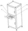
图1:本发明第一实施例中图像采集设备的箱体结构的外部示意图;Fig. 1: The external schematic diagram of the box structure of the image acquisition device in the first embodiment of the present invention;
图2:本发明第一实施例中图像采集设备的箱体结构在打开时的结构示意图;Figure 2: A schematic structural diagram of the box structure of the image acquisition device in the first embodiment of the present invention when it is opened;
图3:本发明第一实施例中承接平台的结构示意图;Figure 3: a schematic structural diagram of a receiving platform in the first embodiment of the present invention;
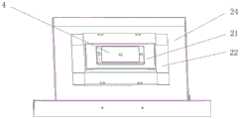
图4:本发明第一实施例中承接板的结构示意图;Figure 4: a schematic structural diagram of a receiving plate in the first embodiment of the present invention;
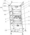
图5:本发明第一实施例中箱体结构在设置有光源时的内部结构示意图;Figure 5: a schematic diagram of the internal structure of the box structure in the first embodiment of the present invention when a light source is provided;
图6:本发明第一实施例中光源和支架本体结合后的结构示意图;Figure 6: a schematic structural diagram of the combination of the light source and the bracket body in the first embodiment of the present invention;
图7:本发明第一实施例中箱体结构在设置有光源时的内部结构示意图;Figure 7: A schematic diagram of the internal structure of the box structure when the light source is provided in the first embodiment of the present invention;
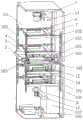
图8:本发明第一实施例中图像采集设备的内部结构示意图;Fig. 8 is a schematic diagram of the internal structure of the image acquisition device in the first embodiment of the present invention;
图9:本发明第一实施例中带有反射镜的承接平台的结构示意图;Figure 9: a schematic structural diagram of a receiving platform with a mirror in the first embodiment of the present invention;
图10:本发明第一实施例中设有光源的支架本体的结构示意图;Figure 10: a schematic structural diagram of a bracket body provided with a light source in the first embodiment of the present invention;
图11:本发明第一实施例中光源的结构示意图;Figure 11: a schematic structural diagram of a light source in the first embodiment of the present invention;
图12:本发明第一实施例中图像采集设备的结构示意图;FIG. 12 is a schematic structural diagram of an image acquisition device in the first embodiment of the present invention;
附图标记说明:第一摄像头1、承接平台2、反射镜3、待测物4、连接件5、光源6、支架本体7、联结件8、第二摄像头9、第二支架11、箱体13、窗口130、上腔体131、下腔体132、上柜门133、下柜门134、显示屏135、第一基梁14、第二基梁15、吊环16、支撑脚17、轨道18、滑轨19、承接板 21、底板22、把手23、安装基板24、凸起部221、内缘面2211、镂空部222、第一本体51、第一滑槽511、第二本体52、第二滑槽521、第三本体53、反射镜本体31、固定板32、转动板33、转孔331、垂直部81、水平部82、圆弧槽83、底座61、轴孔611、灯体62、光源调整条101、光源固定条102、驱动杆103、驱动电机104、固定件105、光源控制器106、工控机107、槽体1011、固定片1012、调整片1013。Description of reference numerals:
具体实施方式Detailed ways
以下将结合附图对本发明的构思、具体结构及产生的技术效果作进一步说明,以充分地了解本发明的目的、特征和效果。The concept, specific structure and technical effects of the present invention will be further described below in conjunction with the accompanying drawings, so as to fully understand the purpose, characteristics and effects of the present invention.
实施例一Example 1
本实施例提供了一种图像采集设备的箱体结构,如图1和图2所示,其主要是由可形成密闭环境的箱体13、开设于箱体13上的窗口130、可滑动地设置于箱体13内并用于放置待测物4的承接平台2、与承接平台2相连并用于带动承接平台2滑动的驱动装置、与驱动装置通讯连接的控制装置等构成。This embodiment provides a box body structure of an image acquisition device, as shown in FIG. 1 and FIG. 2 , which mainly consists of a
其中,承接平台2从窗口130滑入箱体13内部后,封闭窗口130。Wherein, after the
通过上述内容可知:由于箱体13内设有一滑动的承接平台2,箱体13 开设有用于滑出承接平台2的窗口130,并且由于箱体结构还具有用于带动承接平台2滑动的驱动装置,因此可通过控制装置控制驱动装置,使得承接平台2自动从窗口130滑出箱体内部后,通过人工操作或机械手抓取等方式将待测物4放置于承接平台2上,当承接平台2在驱动装置的作用下自动从窗口130滑入箱体的内部后,即可使得待测物4在密闭环境内进行图像采集。因此,本申请提供的箱体结构的结构简单,可实现承接平台2的自动滑动,方便手机、平板电脑等待测物4的取拿,例如通过机械手的配合,实现智能化流水式操作,以替代人工操作,因而可提高工作效率。It can be seen from the above content that since the
具体地,如图5所示,本实施例中的承接平台2将箱体13内部分成上腔体131和下腔体132。箱体结构还包括:设置于上腔体131内并用于悬挂第一摄像头1的第一基梁14、设置于箱体13内并用于将第二摄像头9倒挂于箱体13内的第二基梁15。以方便第一摄像头1和第二摄像头9的固定及其位置的调节,便于其采集图像过程中的校准,节省时间。其中,作为优选的方式,第一基梁14和第二基梁15分别用于活动连接第一摄像头1和第二摄像头9。Specifically, as shown in FIG. 5 , the
进一步作为优选地,如图2所示,承接平台2主要由具有一用于放置待测物4的容纳腔的盒体。其中,盒体的一侧壁用于封闭窗口130。通过将承接平台2滑出窗口130外,便于用户放置手机,并保证承接平台2在封闭窗口130后,箱体内部形成良好的密闭环境,以利于待测物的图像采集等。Further preferably, as shown in FIG. 2 , the receiving
并且,容纳腔的底壁有部分为透明区域,且透明区域形成用于放置待测物4的检测区。In addition, a part of the bottom wall of the accommodating cavity is a transparent area, and the transparent area forms a detection area for placing the object to be tested 4 .
此外,如图3所示,为了便于承接平台2的安装和设置,容纳腔的底壁可以由开设有镂空区(图中未示出)的安装基板24、与安装基板24固定相连的底板22等构成。其中,底板22上有部分为透明区域。In addition, as shown in FIG. 3 , in order to facilitate the installation and setting of the receiving
进一步作为优选地,如图4所示,容纳腔的底壁有部分凸起形成与检测区的形状相匹配的凸起部221,且凸起部221有部分被镂空形成与检测区的形状相匹配的镂空部222。并且,底壁还包括:用于盖合镂空部222并用于放置待测物4且为透明面板的承接板21。通过透明区域有利于摄像头从相对的两个方向分别拍摄待测物4的正面图像和背面图像,以简化操作。另外,待测物4在被测试的过程中,由于其位置是不动的,因此第一摄像头1和第二摄像头9采集的图像可以较好的匹配,进一步简化了结构,方便了工作人员的操作,提高了采集效率,便于后续的图像处理。另外,需要说明的是,本实施例中的凸起部221优选设置于底板22上。Further preferably, as shown in FIG. 4 , a portion of the bottom wall of the accommodating cavity is raised to form a raised
另外,如图1所示,本实施例中盒体可以优选为抽屉,并且,安装基板 24的底部可与相应的轨道和滑轨等滑轨组件相连,以实现抽屉的滑动,即承接平台2的滑动,以便于放置或取出待测物4。此外,承接平台2,即盒体的外壁还设有把手23,以方便用户手工或机械手将盒体从箱体13内部抽出或推入箱体内部。In addition, as shown in FIG. 1 , in this embodiment, the box body can preferably be a drawer, and the bottom of the mounting
进一步作为优选地,如图5所示,箱体结构还包括:设置于箱体13内的轨道18、与承接平台2相连用于滑动连接轨道18的滑轨19。其中,滑轨19 与如图3中所示的安装基板24相连。本实施例中的轨道18和滑轨19均优选为两条,且相互平行,分别设置于底板22的相对两侧。由此,通过轨道18 和滑轨19的配合,实现承接平台22的平稳滑动,且不影响第二摄像头9对待测物4的拍摄。Further preferably, as shown in FIG. 5 , the box body structure further includes: a
进一步作为优选地,如图8所示,驱动装置可以由驱动电机104、与驱动电机104的驱动轴相连并用于带动承接平台2滑动的驱动杆103、与驱动杆103和承接平台2的侧壁相连的固定件105等构成。以通过驱动电机104 驱动驱动杆103,使得承接平台2在固定件105的作用下移动,从而可实现智能化流水式操作。Further preferably, as shown in FIG. 8 , the driving device may be composed of a driving
详细地,如图8所示,本实施例中的驱动电机104优选为丝杆电机。并且,驱动杆103为优选为丝杆;固定件105的一端套设在丝杆上,而另一端与承接平台2相连。其中,当丝杆正向转动时,固定件105推动承接平台2 朝窗口130的外侧移动;当丝杆反向转动时,固定件105推动承接平台2朝窗口130的内侧移动。由此可知,通过驱动电机104、丝杆和固定件105的传动配合,通过较小的推力,即可平稳地推动承接平台22,并精准控制承接平台22的移动距离。In detail, as shown in FIG. 8 , the driving
另外,需要说明的是,本实施例中的驱动电机104还可以根据实际需要,选择为液压电机或气动电机,驱动件为对应的推杆,固定件为相应的连接件等,以实现承接平台的滑动,在此不作赘述。In addition, it should be noted that the driving
进一步作为优选地,如图5和图8所示,箱体结构还包括:与箱体13的内壁相连的光源调整条101、与光源调整条101可拆卸连接的光源固定条102、与光源固定条102可拆卸连接并用于悬挂光源的支架本体7;其中,光源调整条101沿其轴向开设有槽体,用于滑动连接光源固定条102,如通过螺栓等紧固件,如实现彼此之间的锁紧连接。由此可知,借助光源调整条101和光源固定条102之间的配合,实现了支架本体7的高度调节,从而便于调节悬挂在支架本体7上的光源的高度。Further preferably, as shown in FIG. 5 and FIG. 8 , the box body structure further includes: a light
进一步作为优选地,如图5所示,为了方便实际应用中的装配,光源调整条101可以由用于与所述内壁相连的固定片1012、与固定片1012垂直相连并用于与所述光源固定条102可拆卸连接的调整片1013等构成。其中,所述调整片沿其轴向开设有所述槽体1011,且槽体1011的数量可与第一支架7 的数量一一对应。Further preferably, as shown in FIG. 5 , in order to facilitate the assembly in practical applications, the light
进一步作为优选地,如图5所示,本实施例中的光源调整条101和光源固定条102均为多个;各光源调整条101的轴向相互平行,且呈矩形对称分布;各光源固定条102的相对两端均分别与相邻的两条光源调整条101垂直相连;相对且平行的两条光源固定条102分别与支架本体7的相对两侧相连。从而使得光源固定条与支架本体7相连的固定点可以在同一平面内呈矩形分布,进而使得支架本体7不易产生倾斜,有利于支架本体7在箱体13高度方向上的平稳调节,进而减少光源6在调节过程中产生的精度误差。在此,需要说明的是,本实施例的上腔体131和下腔体132内的光源固定条102和光源调整条101的数量均优选为四条,且光源调整条101可以分为多组,每组中的光源固定条102两两相对设置,并用于固定一支架本体7。Further preferably, as shown in FIG. 5 , there are multiple light source adjustment bars 101 and light
进一步作为优选地,如图6所示,支架本体7为开设有镂空区71的支撑面板72。其中,支撑面板72可以由开设有镂空区71的框体部721、与框体部721相连并用于与光源固定条102相连的定位部722等构成。通过该结构不仅可降低支架本体7的重量,还可在安装光源后,不影响摄像头的拍摄的情况下,通过定位部722方便支架本体7与光源固定条102之间的定位连接。Further preferably, as shown in FIG. 6 , the
另外,如图4所示,本申请的箱体结构内从上至下间隔设置有若干个支架本体7。并且各支架本体7均通过联结件8和锁止件设置有光源6,其中,联结件8用于活动连接光源6,并使得光源6悬挂于支架本体7上。锁止件用于在光源6转动至预设角度后,将光源6与联结件8锁紧连接。。因此,通过多组支架本体7可从上至下悬挂多组光源6,以通过两组以上的光源6 的共同配合,使得照射到待测物4表面上的光线保持均匀,同时,借助其中一组光源6照射的光线对另一组光源6照射的光线起到补强光或补弱光的作用,避免待测物4的局部出现亮斑等现象。其中,本实施例仅以两个支架本体7为例作说明,并且,当支架本体7的数量为超过两个时,各支架本体7 等距设置。In addition, as shown in FIG. 4 , in the box structure of the present application,
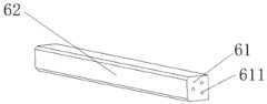
详细地,如图10所示,本实施例中的联结件8主要是由开设有圆弧槽 83的垂直部81、与垂直部81相连并与支架本体7相邻的水平部82、与光源 6的侧壁相连并插入圆弧槽83的支轴(图中未表示)等构成。其中,垂直部 81通过圆弧槽83与支轴形成转动连接;锁止件为用于对支轴锁紧连接的锁紧螺母(图中未表示)。显然,本实施例中的锁紧件不限于锁紧螺母,还可以为对于本领域技术人员来说,现有技术中已知的相关锁紧件,例如夹头、卡扣、插销等,在此不作具体的限定和赘述。In detail, as shown in FIG. 10 , the
由此可知,通过支轴在对应的圆弧槽83之间的滑动,实现光源6的照射角度的调节和固定。值得说的是,本实施例还可采用其他的部件替代锁紧螺母以实现对支轴的锁紧,在此不作具体的限定It can be seen from this that the adjustment and fixation of the irradiation angle of the
此外,如图11所示,作为优选的方式,本实施例中的光源6可由底座 61、开设在底座61上的轴孔611、矩形的灯体62等构成。并且,底座61的端面上开设有转轴孔611至少为两个,其中,一个为轴心孔,另一个为转轴孔。其中,第一光源6在转动时,围绕插入轴心孔的中心轴转动,并且通过插入转轴孔的支轴带动第一光源6的调节,籍此,实现了第一光源6的圆周转动,方便了第一光源6的照射角度的精准控制。其中,本实施例中的转轴孔611优选为两个,且位于同一圆周上。In addition, as shown in FIG. 11, as a preferred way, the
此外,如图1所示,为了方便图像检测设备的吊装和搬运,箱体13的顶部设置有四个吊环16,箱体13的底部设置有四个支撑脚17。In addition, as shown in FIG. 1 , in order to facilitate the hoisting and transporting of the image detection device, the top of the
另外,需要说明的是,如图8所示,本实施例中的控制装置可以由与驱动装置电性连接工控机107、用于与光源6和工控机107电性连接的光源控制器106等构成。In addition, it should be noted that, as shown in FIG. 8 , the control device in this embodiment may consist of a
另外,值得一提的是,如图8和图9所示,本实施例中容纳腔的底壁上可设置多个反射镜3,且各反射镜3可首尾依次相连,围合形成的区域为检测区。以借助反射镜3的配合,使得单个摄像头即可拍摄待测物4的正面图像和侧面图像,同时,通过该设置方式使得反射镜3尽可能地对待测物4的侧部,即其周向形成全方位的包围,避免待测物4的侧部有部分区域,以及倒角区域未显示在反射镜3中,从而避免出现漏检的情形。当然,本实施例中的反射镜 3为多个时,也可以为间隔围绕设置的,仅需保持反射镜3的长度大于待测物 4的长度或宽度即可。In addition, it is worth mentioning that, as shown in FIG. 8 and FIG. 9 , in this embodiment, a plurality of
实施例二
本实施例还提供了一种图像采集设备,可参考图8,其包括:摄像头(可参考上述第一摄像头1或第二摄像头9),光源6,上述实施例中任意一项的箱体结构。其中,所述光源6、所述摄像头和所述控制装置电性连接。This embodiment also provides an image acquisition device, please refer to FIG. 8 , which includes: a camera (refer to the above-mentioned
通过上述内容可知:由于本申请中的图像采集设备的箱体13内设有一滑动的承接平台2,箱体13开设有用于滑出承接平台2的窗口130,并且由于箱体结构还具有用于带动承接平台2滑动的驱动装置,因此可通过控制装置控制驱动装置,使得承接平台2自动从窗口130滑入后,通过人工或机械手,将待测物4放置于承接平台2上后,通过驱动装置带动承接平台2滑入窗口 130内,以便于待测物4在密闭环境的箱体13内进行图像采集。因此,本申请提供的箱体结构结构简单,便于装配,同时可实现承接平台2的自动滑动,方便待检测的产品取拿,例如通过机械手的配合,实现智能化流水式操作,以替代人工操作,可提升工作效率。It can be seen from the above content that since the
具体地,如图12所示,本实施例的图像采集设备还包括:设置于所述箱体的外壁的一显示屏135,且所述显示屏135与所述驱动装置和所述控制装置电性连接。因此,通过显示屏135可显示相关的参数信息,例如摄像头拍摄的图像,参考上述第一摄像头1和第二摄像头9拍摄的图像,以及光源的亮度信息、驱动装置的状态等。Specifically, as shown in FIG. 12 , the image acquisition device of this embodiment further includes: a
进一步作为优选地,本实施例中的显示屏135优选为触控显示屏135,以显示相关的参数信息,同时,便于工作人员更改参数信息,例如光源亮度、承接平台的滑动、摄像头的拍摄参数等信息的调整,省去按钮等结构,起到进一步简化结构的作用。Further preferably, the
详细地,本实施例中,如图12所示,箱体13的外壁具有封闭上腔体131 的上柜门133、封闭下腔体132的下柜门134,该显示屏135可优选设置于上柜门133,以利于节约空间,方便工作人员的观察和操作。In detail, in this embodiment, as shown in FIG. 12 , the outer wall of the
以上实施例仅用以说明本发明的技术方案而非限定,仅仅参照较佳实施例对本发明进行了详细说明。本领域的普通技术人员应当理解,可以对本发明的技术方案进行修改或等同替换,而不脱离本发明技术方案的精神和范围,均应涵盖在本发明的权利要求范围。The above embodiments are only used to illustrate the technical solutions of the present invention and are not intended to limit the present invention. The present invention is only described in detail with reference to the preferred embodiments. It should be understood by those of ordinary skill in the art that the technical solutions of the present invention can be modified or equivalently replaced without departing from the spirit and scope of the technical solutions of the present invention, and should be included in the scope of the claims of the present invention.
Claims (14)
Priority Applications (1)
| Application Number | Priority Date | Filing Date | Title |
|---|---|---|---|
| CN201921640217.3UCN211402187U (en) | 2019-09-27 | 2019-09-27 | Box structure of image acquisition equipment and image acquisition equipment |
Applications Claiming Priority (1)
| Application Number | Priority Date | Filing Date | Title |
|---|---|---|---|
| CN201921640217.3UCN211402187U (en) | 2019-09-27 | 2019-09-27 | Box structure of image acquisition equipment and image acquisition equipment |
Publications (1)
| Publication Number | Publication Date |
|---|---|
| CN211402187Utrue CN211402187U (en) | 2020-09-01 |
Family
ID=72212023
Family Applications (1)
| Application Number | Title | Priority Date | Filing Date |
|---|---|---|---|
| CN201921640217.3UActiveCN211402187U (en) | 2019-09-27 | 2019-09-27 | Box structure of image acquisition equipment and image acquisition equipment |
Country Status (1)
| Country | Link |
|---|---|
| CN (1) | CN211402187U (en) |
Cited By (10)
| Publication number | Priority date | Publication date | Assignee | Title |
|---|---|---|---|---|
| US11798250B2 (en) | 2019-02-18 | 2023-10-24 | Ecoatm, Llc | Neural network based physical condition evaluation of electronic devices, and associated systems and methods |
| US11843206B2 (en) | 2019-02-12 | 2023-12-12 | Ecoatm, Llc | Connector carrier for electronic device kiosk |
| US11922467B2 (en) | 2020-08-17 | 2024-03-05 | ecoATM, Inc. | Evaluating an electronic device using optical character recognition |
| US11989710B2 (en) | 2018-12-19 | 2024-05-21 | Ecoatm, Llc | Systems and methods for vending and/or purchasing mobile phones and other electronic devices |
| US12033454B2 (en) | 2020-08-17 | 2024-07-09 | Ecoatm, Llc | Kiosk for evaluating and purchasing used electronic devices |
| US12271929B2 (en) | 2020-08-17 | 2025-04-08 | Ecoatm Llc | Evaluating an electronic device using a wireless charger |
| US12300059B2 (en) | 2019-02-12 | 2025-05-13 | Ecoatm, Llc | Kiosk for evaluating and purchasing used electronic devices |
| US12321965B2 (en) | 2020-08-25 | 2025-06-03 | Ecoatm, Llc | Evaluating and recycling electronic devices |
| US12322259B2 (en) | 2018-12-19 | 2025-06-03 | Ecoatm, Llc | Systems and methods for vending and/or purchasing mobile phones and other electronic devices |
| US12380420B2 (en) | 2019-12-18 | 2025-08-05 | Ecoatm, Llc | Systems and methods for vending and/or purchasing mobile phones and other electronic devices |
- 2019
- 2019-09-27CNCN201921640217.3Upatent/CN211402187U/enactiveActive
Cited By (11)
| Publication number | Priority date | Publication date | Assignee | Title |
|---|---|---|---|---|
| US11989710B2 (en) | 2018-12-19 | 2024-05-21 | Ecoatm, Llc | Systems and methods for vending and/or purchasing mobile phones and other electronic devices |
| US12322259B2 (en) | 2018-12-19 | 2025-06-03 | Ecoatm, Llc | Systems and methods for vending and/or purchasing mobile phones and other electronic devices |
| US11843206B2 (en) | 2019-02-12 | 2023-12-12 | Ecoatm, Llc | Connector carrier for electronic device kiosk |
| US12300059B2 (en) | 2019-02-12 | 2025-05-13 | Ecoatm, Llc | Kiosk for evaluating and purchasing used electronic devices |
| US11798250B2 (en) | 2019-02-18 | 2023-10-24 | Ecoatm, Llc | Neural network based physical condition evaluation of electronic devices, and associated systems and methods |
| US12223684B2 (en) | 2019-02-18 | 2025-02-11 | Ecoatm, Llc | Neural network based physical condition evaluation of electronic devices, and associated systems and methods |
| US12380420B2 (en) | 2019-12-18 | 2025-08-05 | Ecoatm, Llc | Systems and methods for vending and/or purchasing mobile phones and other electronic devices |
| US11922467B2 (en) | 2020-08-17 | 2024-03-05 | ecoATM, Inc. | Evaluating an electronic device using optical character recognition |
| US12033454B2 (en) | 2020-08-17 | 2024-07-09 | Ecoatm, Llc | Kiosk for evaluating and purchasing used electronic devices |
| US12271929B2 (en) | 2020-08-17 | 2025-04-08 | Ecoatm Llc | Evaluating an electronic device using a wireless charger |
| US12321965B2 (en) | 2020-08-25 | 2025-06-03 | Ecoatm, Llc | Evaluating and recycling electronic devices |
Similar Documents
| Publication | Publication Date | Title |
|---|---|---|
| CN211402187U (en) | Box structure of image acquisition equipment and image acquisition equipment | |
| CN211291337U (en) | Image acquisition device and image detection equipment | |
| CN212031269U (en) | Mirror body installing support, imaging device and image acquisition equipment | |
| CN110595361A (en) | Image acquisition device and image detection equipment | |
| CN107270816B (en) | Auxiliary material detection equipment for mobile phone and tablet personal computer | |
| CN206944935U (en) | A kind of mobile phone, tablet personal computer auxiliary material detection device | |
| CN216391264U (en) | Full-automatic analysis test equipment of camera image effect | |
| CN206638174U (en) | Surgery operating sample information acquiring instrument | |
| CN213021938U (en) | Device for setting and measuring illuminance | |
| CN212083264U (en) | Product appearance detection device | |
| CN210442278U (en) | Chip surface detection device | |
| CN220039785U (en) | Endoscope optical test tool | |
| CN205405612U (en) | Device of shooing of counting of corrugated paper | |
| CN216593711U (en) | Mushroom fruiting body weight and phenotype character measuring device | |
| CN219552282U (en) | Glass packaging thermistor detection equipment | |
| CN208661788U (en) | Optical detector | |
| CN205910077U (en) | Automatic test system is extended to cable heat | |
| CN110723478A (en) | Display panel overhauls device | |
| CN210694148U (en) | Focusing and focusing device of camera | |
| CN115389428A (en) | Appearance detection equipment for metal ring glass protective cover | |
| CN110174563A (en) | Automatic testing equipment | |
| CN206113858U (en) | Hole check out test set | |
| WO2023071286A1 (en) | Fabric scanning apparatus | |
| CN210719057U (en) | Visual inspection device | |
| CN114160434A (en) | A dynamic sorting and handling automation system |
Legal Events
| Date | Code | Title | Description |
|---|---|---|---|
| GR01 | Patent grant | ||
| GR01 | Patent grant | ||
| CP01 | Change in the name or title of a patent holder | ||
| CP01 | Change in the name or title of a patent holder | Address after:Room 1101-1103, No. 433, Songhu Road, Yangpu District, Shanghai Patentee after:Shanghai wanwansheng Environmental Protection Technology Group Co.,Ltd. Address before:Room 1101-1103, No. 433, Songhu Road, Yangpu District, Shanghai Patentee before:SHANGHAI YUEYI NETWORK INFORMATION TECHNOLOGY Co.,Ltd. | |
| CP03 | Change of name, title or address | ||
| CP03 | Change of name, title or address | Address after:Room 1101-1103, No. 433, Songhu Road, Yangpu District, Shanghai Patentee after:Shanghai Wanwu Xinsheng Information Technology Group Co.,Ltd. Country or region after:China Address before:Room 1101-1103, No. 433, Songhu Road, Yangpu District, Shanghai Patentee before:Shanghai wanwansheng Environmental Protection Technology Group Co.,Ltd. Country or region before:China |