CN211381596U - An end component of an orthopaedic joint replacement surgical system - Google Patents
An end component of an orthopaedic joint replacement surgical systemDownload PDFInfo
- Publication number
- CN211381596U CN211381596UCN201921339572.7UCN201921339572UCN211381596UCN 211381596 UCN211381596 UCN 211381596UCN 201921339572 UCN201921339572 UCN 201921339572UCN 211381596 UCN211381596 UCN 211381596U
- Authority
- CN
- China
- Prior art keywords
- main shaft
- shaft
- casing
- main
- grinding
- Prior art date
- Legal status (The legal status is an assumption and is not a legal conclusion. Google has not performed a legal analysis and makes no representation as to the accuracy of the status listed.)
- Active
Links
Images


Classifications
- A—HUMAN NECESSITIES
- A61—MEDICAL OR VETERINARY SCIENCE; HYGIENE
- A61B—DIAGNOSIS; SURGERY; IDENTIFICATION
- A61B34/00—Computer-aided surgery; Manipulators or robots specially adapted for use in surgery
- A61B34/30—Surgical robots
Landscapes
- Prostheses (AREA)
Abstract
Translated fromChinese
Description
Translated fromChinese技术领域technical field
本实用新型涉及骨科关节置换技术领域,尤其是涉及一种骨科关节置换手术系统的末端组件。The utility model relates to the technical field of orthopedic joint replacement, in particular to an end component of an orthopedic joint replacement operation system.
背景技术Background technique
随着目前科学技术的发展,在医疗手术过程中,医疗机器人的应用也越来越广泛,因为其使得外科医生能够保持对于术程序的直接亲自控制,同时仍能达成高准确度和/或精确度。目前公告号为CN 102612350 B的发明专利公开了一种用于安放假体组件和/或限制手术工具移动的手术系统,包括计算机辅助导航系统、跟踪装置、显示器装置和机器人臂。大致手术过程如下,外科医生使用扩孔器重整髓臼的表面并将天然表面置换为假体髓臼组件,假体髓臼组件包含髋臼杯,髋臼杯内壁上设有衬垫。手术时,外科医生将髋臼杯连接至冲击器工具的远端并通过用木槌重复击打冲击器工具的近端将髋臼杯植入经过扩孔的髓臼窝中。With the current development of science and technology, medical robots are more widely used in medical procedures, because they allow the surgeon to maintain direct personal control of the surgical procedure, while still achieving a high degree of accuracy and/or precision Spend. The present invention patent publication number CN 102612350 B discloses a surgical system for placing a prosthesis assembly and/or restricting the movement of surgical tools, including a computer-aided navigation system, a tracking device, a display device and a robotic arm. The general procedure is as follows. The surgeon uses a reamer to resurface the acetabular cup and replaces the natural surface with a prosthetic acetabular component containing an acetabular cup with a liner on the inner wall of the acetabular cup. During surgery, the surgeon attaches the acetabular cup to the distal end of the impactor tool and implants the acetabular cup into the reamed acetabular fossa by repeatedly hitting the proximal end of the impactor tool with a mallet.
在机器人手臂端部需要安装末端执行器,末端执行器用于安装髋臼锉,包括安装在机器人手臂上的外壳,外壳内设有主轴,主轴可以在外壳内转动以及滑移,主轴一端连接髋臼锉,另一端连接电钻,手术时,机器人手臂会先将主轴以及髋臼锉定位到髋臼窝前端,并且调整好进给方向,随后外壳医生手动操作主轴滑动,控制髋臼锉的进给量,对髋臼窝进行打磨。An end effector needs to be installed at the end of the robot arm. The end effector is used to install the acetabular ream, including a casing installed on the robot arm. The casing is provided with a main shaft. The main shaft can rotate and slide in the casing. One end of the main shaft is connected to the acetabulum. File, the other end is connected to an electric drill. During the operation, the robot arm will first position the spindle and the acetabular file to the front of the acetabular fossa, and adjust the feeding direction. Then the shell doctor manually slides the spindle to control the feeding amount of the acetabular file. , to grind the acetabular fossa.
在实际操作过程中,主轴端部仅仅只能安装髋臼锉,当髋臼锉对髋臼窝打磨完毕之后,还需要更换冲击器工具,将髋臼杯敲入髋臼窝内,才能完成髋臼杯的安装,需要使用到多种器械搭配才能完成手术过程,操作十分不方便。In the actual operation, only the acetabular ream can be installed at the end of the main shaft. After the acetabular ream has finished grinding the acetabular fossa, it is necessary to replace the impactor tool and knock the acetabular cup into the acetabular fossa to complete the hip ream. The installation of the cup requires the use of a variety of instruments to complete the surgical process, which is very inconvenient to operate.
实用新型内容Utility model content
本实用新型的目的是提供一种骨科关节置换手术系统的末端组件,既可实现对髋臼窝的打磨也可以实现髋臼杯的安装。The purpose of the utility model is to provide an end component of an orthopaedic joint replacement operation system, which can realize both the grinding of the acetabular fossa and the installation of the acetabular cup.
本实用新型的上述实用新型目的是通过以下技术方案得以实现的:一种骨科关节置换手术系统的末端组件,包括与机器人手臂固定的壳体,所述壳体内设有主轴,所述主轴与壳体同轴设置,所述主轴与壳体转动连接且能沿壳体轴线方向滑移,所述主轴端部与主轴同轴设有磨削轴,所述磨削轴端部设有髋臼锉,所述主轴端部设有用于固定磨削轴的固定装置;还包括通过固定装置固定在主轴端部的安装轴,所述安装轴远离主轴一端设有髋臼杯。The above utility model purpose of the present invention is achieved through the following technical solutions: an end component of an orthopaedic joint replacement surgery system, comprising a casing fixed with a robot arm, the casing is provided with a main shaft, and the main shaft is connected to the casing. The main shaft is coaxially arranged with the casing, the main shaft is rotatably connected with the casing and can slide along the axial direction of the casing, the end of the main shaft and the main shaft are coaxially provided with a grinding shaft, and the end of the grinding shaft is provided with an acetabular file , the end of the main shaft is provided with a fixing device for fixing the grinding shaft; it also includes an installation shaft fixed on the end of the main shaft through the fixing device, and an acetabular cup is provided at one end of the installation shaft away from the main shaft.
通过采用上述技术方案,手术时,磨削轴通过固定装置固定在主轴一端,主轴另一端与电钻相连,机器人手臂将主轴定位完毕之后,开启电钻,电钻带动主轴以及磨削轴转动,同时外科医生推动主轴在壳体上滑动,对髋臼进行磨削;磨削完毕之后,解除固定装置的固定,将磨削轴拆卸下来,更换上安装轴,同时将电钻拆卸下来,直接敲击主轴,即可将安装轴上的髋臼杯敲入髋臼内,不需要更换末端组件。By adopting the above technical solution, during the operation, the grinding shaft is fixed on one end of the main shaft by the fixing device, and the other end of the main shaft is connected with the electric drill. After the robot arm has positioned the main shaft, the electric drill is turned on, and the electric drill drives the main shaft and the grinding shaft to rotate. Push the main shaft to slide on the shell to grind the acetabulum; after grinding, release the fixing device, remove the grinding shaft, replace the installation shaft, remove the electric drill at the same time, and directly tap the main shaft, that is The acetabular cup on the mounting shaft can be tapped into the acetabulum without the need to replace the tip assembly.
本实用新型进一步设置为:所述固定装置包括设置在主轴端部的沉孔,所述沉孔内径与安装轴以及磨削轴外径相等,所述沉孔与主轴同轴设置,所述安装轴以及磨削轴外周面上设有凸块,所述主轴端面设有供凸块插入的开口槽,所述主轴外周面上沿主轴径向滑移设有能够部分伸入沉孔内的滚珠,所述安装轴以及磨削轴上设有在插入沉孔内后供滚珠嵌入的环形槽,所述主轴上设有驱动滚珠保持在嵌入环形槽状态的固定件。The utility model is further provided as follows: the fixing device comprises a counterbore arranged at the end of the main shaft, the inner diameter of the counterbore is equal to the outer diameter of the installation shaft and the grinding shaft, the counterbore is coaxial with the main shaft, and the installation There are bumps on the outer peripheral surface of the shaft and the grinding shaft, the end face of the main shaft is provided with an open groove for the bumps to be inserted, and the outer peripheral surface of the main shaft is sliding along the radial direction of the main shaft with balls that can partially extend into the counterbore , the installation shaft and the grinding shaft are provided with annular grooves for the balls to be embedded after being inserted into the countersunk holes, and the main shaft is provided with a fixing member for driving the balls to keep the state of being embedded in the annular grooves.
通过采用上述技术方案,当安装轴或者磨削轴插入沉孔内时,凸块插入开口槽内,设置凸块以及开口槽,可以限制安装轴以及磨削轴与主轴出现周向转动,当安装轴以及磨削轴插入沉孔内之后,滚珠位于沉孔内的部分嵌入环形槽内,由于设置了固定件,滚珠可以始终保持在环形槽内,滚珠即可限制安装轴以及磨削轴滑动,从而实现主轴与磨削轴或安装轴之间的固定。By adopting the above technical solution, when the installation shaft or the grinding shaft is inserted into the counterbore, the convex block is inserted into the open groove, and the convex block and the open groove are arranged to limit the circumferential rotation of the installation shaft, the grinding shaft and the main shaft. After the shaft and the grinding shaft are inserted into the counterbore, the part of the ball located in the counterbore is embedded in the annular groove. Due to the fixed part, the ball can always be kept in the annular groove, and the ball can limit the sliding of the installation shaft and the grinding shaft. Thus, the fixation between the main shaft and the grinding shaft or the mounting shaft is realized.
本实用新型进一步设置为:所述主轴外周面上沿主轴径向设有用于安装滚珠的锥形孔,所述锥形孔与沉孔相通,所述固定件包括套设在主轴上且位于锥形孔外的锁紧套,所述锁紧套沿主轴轴向与主轴滑移连接,所述锁紧套内壁上设有在滚珠嵌入环形槽内时与滚珠抵接的凸环。The utility model is further provided as follows: the outer peripheral surface of the main shaft is provided with a tapered hole for installing the ball along the radial direction of the main shaft, the tapered hole is communicated with the counterbore, and the fixing member comprises a sleeve sleeved on the main shaft and located in the tapered hole. A locking sleeve outside the shaped hole is slidably connected to the main shaft along the axial direction of the main shaft, and the inner wall of the locking sleeve is provided with a convex ring abutting against the ball when the ball is embedded in the annular groove.
通过采用上述技术方案,当需要固定滚珠时,只需要将凸环滑移到锥形孔外,凸环与滚珠抵接,此时滚珠即可保持在环形槽内,当想要拆卸磨削轴或者安装轴时,只需要滑动锁紧套,将凸环从锥形槽外移出,此时滚珠即可在主轴上滑动,即可将磨削轴或者安装轴从主轴上拆卸下来。By adopting the above technical solution, when the ball needs to be fixed, it is only necessary to slide the convex ring out of the tapered hole, and the convex ring is in contact with the ball. At this time, the ball can be kept in the annular groove. When you want to disassemble the grinding shaft Or when installing the shaft, it is only necessary to slide the locking sleeve to move the convex ring out of the conical groove. At this time, the ball can slide on the main shaft, and the grinding shaft or the installation shaft can be removed from the main shaft.
本实用新型进一步设置为:所述主轴外套设有锁紧弹簧,所述锁紧弹簧一端与主轴抵接另一端与凸环侧面抵接,所述主轴外周面上套设有橡胶圈,所述橡胶圈位于凸环远离锁紧弹簧一侧。The utility model is further configured as follows: the outer casing of the main shaft is provided with a locking spring, one end of the locking spring abuts against the main shaft and the other end abuts against the side surface of the convex ring, a rubber ring is sleeved on the outer peripheral surface of the main shaft, and the The rubber ring is located on the side of the collar away from the locking spring.
通过采用上述技术方案,当锁紧弹簧处于原长时,凸环位于锥形孔外,橡胶圈位于锁紧套内,橡胶圈设置在凸环远离锁紧弹簧一侧,设置橡胶圈,可以避免在拆卸磨削轴或者安装轴时,滚珠从锁紧套与主轴之间的缝隙内掉出,设置锁紧弹簧,可以让凸环默认位于锥形孔外,提高了磨削轴以及安装轴固定过程中的安全性。By adopting the above technical solution, when the locking spring is at its original length, the convex ring is located outside the conical hole, the rubber ring is located in the locking sleeve, and the rubber ring is arranged on the side of the convex ring away from the locking spring. When removing the grinding shaft or installing the shaft, the balls fall out from the gap between the locking sleeve and the main shaft. Setting the locking spring can make the convex ring be located outside the tapered hole by default, which improves the fixing of the grinding shaft and the installation shaft. safety in the process.
本实用新型进一步设置为:所述壳体内沿壳体轴线方向滑移设有主套筒,所述主套筒与主轴转动连接。The utility model is further provided that: a main sleeve is slidably arranged in the casing along the axial direction of the casing, and the main sleeve is rotatably connected with the main shaft.
通过采用上述技术方案,通过设置主套筒,主套筒既可以带动主轴在壳体内滑动,也可以带动主轴转动,可以十分稳定可靠的实现主轴与壳体的连接。By adopting the above technical solution, by providing the main sleeve, the main sleeve can not only drive the main shaft to slide in the casing, but also can drive the main shaft to rotate, which can realize the connection between the main shaft and the casing very stably and reliably.
本实用新型进一步设置为:所述壳体上沿壳体轴线方向设有腰形槽,所述主套筒上设有限位柱,所述限位柱滑移设置在腰形槽内,所述壳体外周面上位于腰形槽外套设有限位环,所述限位环与壳体螺纹连接。The utility model is further configured as follows: the casing is provided with a waist-shaped groove along the axial direction of the casing, a limiting column is provided on the main sleeve, and the limiting column is slidably arranged in the waist-shaped groove, and the A limiting ring is provided on the outer peripheral surface of the casing on the outer sleeve of the waist-shaped groove, and the limiting ring is threadedly connected with the casing.
通过采用上述技术方案,通过设置限位柱以及限位槽,可对主套筒起到限位作用,这样主套筒仅仅只能滑动,无法转动,通过调节限位环的位置,使得限位柱与限位环端面抵接,限位环可以对主套筒的滑移范围起到限位,这样可以方便控制髋臼锉的最大进给量,避免出现进给超限的问题,从而保证磨削精度以及手术效果。By adopting the above technical solution, by setting the limit post and the limit groove, the main sleeve can be limited, so that the main sleeve can only slide and cannot rotate. By adjusting the position of the limit ring, the limit The column is in contact with the end face of the limit ring, and the limit ring can limit the sliding range of the main sleeve, which can easily control the maximum feed amount of the acetabular file, avoid the problem of over-feeding, and ensure Grinding accuracy and surgical results.
本实用新型进一步设置为:所述主套筒与腰形槽对应的表面上沿主轴轴向设有刻度。The utility model is further configured as follows: a scale is arranged on the surface of the main sleeve corresponding to the waist-shaped groove along the axial direction of the main shaft.
通过采用上述技术方案,通过在主套筒上设置刻度,可以方便调节限位环位置,实现限位环的固定。By adopting the above-mentioned technical scheme, by setting a scale on the main sleeve, the position of the limit ring can be adjusted conveniently, and the fixing of the limit ring can be realized.
本实用新型进一步设置为:所述刻度为两列对称设置在限位柱两侧。The utility model is further configured as follows: the scales are symmetrically arranged in two columns on both sides of the limiting column.
通过采用上述技术方案,在进给过程中,即使位于限位柱一侧的刻度滑动到壳体内部,通过观察远离限位环一侧的刻度,即刻度位于腰形槽内的多少,也可判断当前进给量,方便外壳医生在手术时观察当前磨削进度。By adopting the above technical solution, during the feeding process, even if the scale on the side of the limit column slides into the inside of the housing, by observing the scale on the side away from the limit ring, that is, how much the scale is located in the waist-shaped groove, it can be Judging the current feed rate, it is convenient for the shell doctor to observe the current grinding progress during the operation.
本实用新型进一步设置为:所述主套筒内设有至少两个圆锥滚子轴承,所述圆锥滚子轴承的内圈与主轴转动连接,所述壳体内设有驱动主套筒朝向远离髋臼锉一端滑动的复位弹簧。The utility model is further provided as follows: at least two tapered roller bearings are arranged in the main sleeve, the inner ring of the tapered roller bearing is rotatably connected with the main shaft, and the housing is provided with a drive main sleeve to move away from the hip A return spring that slides at one end of the file.
通过采用上述技术方案,圆锥滚子轴承的内圈与主轴转动连接,圆锥滚子轴承可以同时承受周向以及周向受力,可以对主轴起到十分好的支撑,设置复位弹簧这样髋臼锉默认是处于回缩状态,即远离病人的状态,这样不仅可以方便操控,也可以提高手术过程中的安全性。By adopting the above technical solution, the inner ring of the tapered roller bearing is rotatably connected with the main shaft, the tapered roller bearing can bear the circumferential and circumferential forces at the same time, and can support the main shaft very well. The default is to be in a retracted state, that is, away from the patient, which not only facilitates manipulation, but also improves the safety during surgery.
本实用新型进一步设置为:所述主轴末端通过固定装置连接有电钻或受力板。The utility model is further provided that: the end of the main shaft is connected with an electric drill or a force plate through a fixing device.
本实用新型进一步设置为:在安装髋臼杯之前,需要在主轴远离髋臼杯的一端安装受力板,以增大主轴的受力面积,降低主轴的损伤,为方便在主轴上切换电钻或者受力板,主轴末端也是通过固定装置连接电钻或受力板,这样电钻或者受力板均是可拆卸设置在主轴上的,安装以及拆卸十分方便。The utility model is further arranged as follows: before installing the acetabular cup, a force-bearing plate needs to be installed at the end of the main shaft away from the acetabular cup, so as to increase the force-bearing area of the main shaft and reduce the damage of the main shaft. The force-bearing plate and the end of the main shaft are also connected to the electric drill or the force-bearing plate through the fixing device, so that the electric drill or the force-bearing plate can be detachably arranged on the main shaft, and the installation and disassembly are very convenient.
综上所述,本实用新型的有益技术效果为:To sum up, the beneficial technical effects of the present utility model are:
1.即可实现磨削也可以实现髋臼杯的安装,功能十分多样;1. It can realize both grinding and installation of acetabular cup, and the functions are very diverse;
2.只需要滑动锁紧套,即可实现安装轴或者磨削轴的拆卸,操作十分方便。2. It is only necessary to slide the locking sleeve to realize the disassembly of the installation shaft or the grinding shaft, which is very convenient to operate.
附图说明Description of drawings
图1是本实用新型的整体结构示意图。Figure 1 is a schematic diagram of the overall structure of the present invention.
图2是图1中竖直方向剖视图。FIG. 2 is a vertical cross-sectional view of FIG. 1 .
图3是本实用新型的磨削轴与主轴安装示意图。FIG. 3 is a schematic diagram of the installation of the grinding shaft and the main shaft of the present invention.
图4是本实用新型的主套筒安装示意图。FIG. 4 is a schematic diagram of the installation of the main sleeve of the present invention.
图中,1、壳体;11、直把手;12、法兰盘;13、复位弹簧;14、腰形槽;15、限位环;2、主轴;21、沉孔;22、开口槽;23、锁紧套;231、凸环;24、锁紧弹簧;25、橡胶圈;26、锥形孔;261、滚珠;3、磨削轴;31、髋臼锉;4、安装轴;41、髋臼杯;5、受力板;6、凸块;7、环形槽;8、主套筒;81、圆锥滚子轴承;82、限位柱;83、刻度。In the figure, 1. Housing; 11. Straight handle; 12. Flange plate; 13. Return spring; 14. Waist-shaped groove; 15. Limit ring; 2. Main shaft; 21. Counterbore; 22. Open slot; 23, locking sleeve; 231, convex ring; 24, locking spring; 25, rubber ring; 26, tapered hole; 261, ball; 3, grinding shaft; 31, acetabular file; 4, installation shaft; 41 , acetabular cup; 5, stress plate; 6, bump; 7, annular groove; 8, main sleeve; 81, tapered roller bearing; 82, limit column; 83, scale.
具体实施方式Detailed ways
以下结合附图1-4对本实用新型作进一步详细说明。The present utility model will be further described in detail below in conjunction with accompanying drawings 1-4.
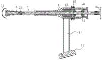
参照图1,为本实用新型公开的一种骨科关节置换手术系统的末端组件,包括与机器人手臂固定的壳体1,壳体1呈圆柱状设置,在壳体1外部固定有直把手11,直把手11一端和壳体1固定连接,另一端固定有法兰盘12,法兰盘12与机器人手臂固定。在壳体1内设有主轴2,主轴2与壳体1同轴设置,主轴2与壳体1转动连接且能沿壳体1轴线方向滑移,在主轴2端部与主轴2同轴设有磨削轴3,磨削轴3端部设有髋臼锉31,主轴2端部设有用于固定磨削轴3的固定装置;还包括通过固定装置固定在主轴2端部的安装轴4,安装轴4远离主轴2一端设有髋臼杯41。Referring to FIG. 1 , it is an end assembly of an orthopaedic joint replacement surgery system disclosed by the utility model, including a casing 1 fixed with a robot arm, the casing 1 is arranged in a cylindrical shape, and a straight handle 11 is fixed outside the casing 1 , One end of the straight handle 11 is fixedly connected with the housing 1, and the other end is fixed with a
参照图1,手术时,磨削轴3通过固定装置固定在主轴2一端,主轴2另一端与电钻相连,机器人手臂将主轴2定位完毕之后,开启电钻,电钻带动主轴2以及磨削轴3转动,同时外科医生推动主轴2在壳体1上滑动,对髋臼进行磨削,磨削完毕之后,解除固定装置的固定,将磨削轴3拆卸下来,更换上安装轴4,同时将电钻拆卸下来,直接敲击主轴2,即可将安装轴4上的髋臼杯41敲入髋臼内。1, during the operation, the grinding
此外,参照图1,为提高安装轴4以及磨削轴3的利用率,髋臼锉31与磨削轴3之间、髋臼杯41与安装轴4之间,均是可拆卸固定连接,连接结构可以采用现有技术中的固定结构,在此不做过多赘述。In addition, referring to FIG. 1 , in order to improve the utilization rate of the installation shaft 4 and the grinding
参照图2以及图3,固定装置包括设置在主轴2端部的沉孔21,沉孔21内径与安装轴4以及磨削轴3外径相等,沉孔21与主轴2同轴设置,这样可以保证主轴2转动时安装轴4以及磨削轴3不会出现摆动,在安装轴4以及磨削轴3的外周面上设有凸块6,主轴2端面上设有供凸块6插入的开口槽22,当安装轴4或者磨削轴3插入沉孔21内时,凸块6插入开口槽22内,设置凸块6以及开口槽22,可以限制安装轴4以及磨削轴3与主轴2出现周向转动,此时只需要对安装轴4以及磨削轴3的轴线方向进行限位即可。2 and 3, the fixing device includes a
参照图2以及图3,为避免安装轴4以及磨削轴3从沉孔21内滑出,在主轴2外周面上沿主轴2径向滑移设有能够部分伸入沉孔21内的滚珠261,滚珠261位于沉孔21内的体积小于滚珠261体积的二分之一,安装轴4以及磨削轴3上设有在插入沉孔21内后供滚珠261嵌入的环形槽7,主轴2上设有驱动滚珠261保持在嵌入环形槽7状态的固定件。当安装轴4以及磨削轴3插入沉孔21内之后,滚珠261位于沉孔21内的部分嵌入环形槽7内,由于设置了固定件,滚珠261可以始终保持在环形槽7内,滚珠261即可限制安装轴4以及磨削轴3滑动。2 and 3 , in order to prevent the mounting shaft 4 and the grinding
参照图2以及图3,在主轴2外周面上沿主轴2径向设有用于安装滚珠261的锥形孔26,锥形孔26一端与外界相通,另一端与沉孔21相通,锥形孔26的大径端位于主轴2外周面上,锥形孔26的小径小于滚珠261的直径,这样可以避免滚珠261从锥形孔26内掉出,固定件包括套设在主轴2上且位于锥形孔26外的锁紧套23,锁紧套23可以沿着主轴2的轴向滑动,锁紧套23沿主轴2轴向与主轴2滑移连接,锁紧套23内壁上设有在滚珠261嵌入环形槽7内时与滚珠261抵接的凸环231,当需要固定滚珠261时,只需要将凸环231滑移到锥形孔26外,凸环231与滚珠261抵接,此时滚珠261即可保持在环形槽7内,当想要拆卸磨削轴3或者安装轴4时,只需要滑动锁紧套23,将凸环231从锥形槽外移出,此时滚珠261即可在主轴2上滑动,即可将磨削轴3或者安装轴4从主轴2上拆卸下来。2 and 3, a
参照图2以及图3,为实现锁紧套23的固定,在主轴2外套设有锁紧弹簧24,锁紧弹簧24一端与主轴2抵接另一端与凸环231侧面抵接,当锁紧弹簧24处于原长时,凸环231位于锥形孔26外,为避免在拆卸磨削轴3或者安装轴4,滚珠261从锁紧套23与主轴2之间的缝隙内掉出,在主轴2外周面上套设有橡胶圈25,橡胶圈25位于锁紧套23内,橡胶圈25设置在凸环231远离锁紧弹簧24一侧,设置锁紧弹簧24,可以让凸环231默认位于锥形孔26外,提高了磨削轴3以及安装轴4固定过程中的安全性。2 and 3 , in order to realize the fixation of the locking
参照图2以及图4,为实现主轴2与壳体1之间的转动以及滑移,在壳体1内沿壳体1轴线方向滑移设有主套筒8,主套筒8的外径与壳体1内径相等,主套筒8与主轴2转动连接。通过设置主套筒8,主套筒8既可以带动主轴2在壳体1内滑动,也可以带动主轴2转动,可以十分稳定可靠的实现主轴2与壳体1的连接。在主套筒8内设有至少两个圆锥滚子轴承81的外圈与主套筒8内壁固定,圆锥滚子轴承81的内圈与主轴2转动连接,圆锥滚子轴承81可以同时承受周向以及周向受力,可以对主轴2起到十分好的支撑,在壳体1内设有驱动主套筒8朝向远离髋臼锉31一端滑动的复位弹簧13,设置复位弹簧13这样髋臼锉31默认是处于回缩状态,即远离病人的状态,这样不仅可以方便操控,也可以提高手术过程中的安全性。2 and 4, in order to realize the rotation and sliding between the
参照图2以及图4,壳体1上沿壳体1轴线方向有腰形槽14,在主套筒8上设有限位柱82,限位柱82沿主套筒8的径向设置,限位柱82端部与主套筒8螺纹连接,限位柱82与腰形槽14配合,限位柱82滑移设置在腰形槽14内,通过设置限位柱82以及限位槽,可对主套筒8起到限位作用,这样主套筒8仅仅只能滑动,无法转动,壳体1外周面上位于腰形槽14外套设有限位环15,限位环15与壳体1螺纹连接,通过调节限位环15的位置,使得限位柱82与限位环15端面抵接,限位环15可以对主套筒8的滑移范围起到限位,这样可以方便控制髋臼锉31的最大进给量,避免出现进给超限的问题,从而保证磨削精度以及手术效果。2 and 4 , there is a waist-shaped groove 14 on the housing 1 along the axial direction of the housing 1, and a limit post 82 is provided on the main sleeve 8, and the limit post 82 is arranged along the radial direction of the main sleeve 8 to limit The end of the positioning column 82 is threadedly connected with the main sleeve 8, the limiting column 82 is matched with the waist-shaped groove 14, and the limiting column 82 is slidably arranged in the waist-shaped groove 14. The main sleeve 8 has a limiting effect, so that the main sleeve 8 can only slide and cannot rotate. The outer peripheral surface of the casing 1 is located in the waist-shaped groove 14. The outer casing is provided with a limiting ring 15. The limiting ring 15 and the casing 1 Threaded connection, by adjusting the position of the limit ring 15, the limit post 82 is in contact with the end face of the limit ring 15, and the limit ring 15 can limit the sliding range of the main sleeve 8, which can facilitate the control of the hip The maximum feed amount of the
参照图2以及图4,为了方便调整限位环15的位置,对最大进给量的范围进行调节,在主套筒8与腰形槽14对应的表面上沿主轴2轴向设有刻度83,刻度83以限位杆为原点沿主轴2轴向延伸,将刻度83与主套筒8对应设置,可以方便观察刻度83。初始状态,限位柱82是位于腰形槽14一端的,以限位柱82为原点,参照主套筒8上的刻度83,即可实现限位环15位置的调节,方便对主套筒8滑动范围进行调节。同时,为了避免限位环15出现松动,本实施例中,限位环15为两个,两个限位环15可以互相抵紧,避免限位环15出现自转,影响定位精度。2 and 4, in order to adjust the position of the limit ring 15 conveniently and adjust the range of the maximum feed amount, a scale 83 is provided on the surface of the main sleeve 8 corresponding to the waist groove 14 along the axial direction of the
此外,参照图2以及图4,为了方便在磨削过程中观察磨削精度,刻度83为两列对称设置在限位柱82两侧,这样在进给过程中,即使位于限位柱82一侧的刻度83滑动到壳体1内部,通过观察远离限位环15一侧的刻度83,即刻度83位于腰形槽14内的多少,即可判断当前进给量,方便外壳医生在手术时观察当前磨削进度。In addition, referring to FIGS. 2 and 4 , in order to facilitate the observation of the grinding accuracy during the grinding process, the scales 83 are symmetrically arranged in two rows on both sides of the limit post 82 , so that during the feeding process, even if it is located at one of the limit posts 82 The scale 83 on the side slides into the housing 1, and by observing the scale 83 on the side away from the limit ring 15, that is, how much the scale 83 is located in the waist-shaped groove 14, the current feed rate can be judged, which is convenient for the shell doctor during the operation. Observe the current grinding progress.
此外,参照图2以及图4,在安装髋臼杯41时,需要对主轴2进行敲击,为降低主轴2的损伤,在安装髋臼杯41之前,需要在主轴2远离髋臼杯41的一端安装受力板5,以增大主轴2的受力面积,为方便在主轴2上切换电钻或者受力板5,主轴2末端通过固定装置连接有电钻或受力板5,这样电钻或者受力板5均是可拆卸设置在主轴2上的,安装以及拆卸十分方便,固定装置的结构与主轴2和磨削轴3的固定结构类似,在此不再赘述。In addition, referring to FIG. 2 and FIG. 4 , when installing the acetabular cup 41 , it is necessary to knock the
本实施例的实施原理为:手术时,当需要对髋臼杯41进行打磨的时候,先在主轴2上安装磨削轴3,将磨削轴3插入沉孔21内,滚珠261嵌入环形槽7内,磨削轴3上的凸块6嵌入开口槽22内,随后松开锁紧套23,锁紧套23将滚珠261限制在锥形孔26内,滚珠261即可将磨削轴3固定在主轴2上,随后再在磨削轴3上安装上髋臼锉31,即可实现磨削轴3的固定,最后再将电钻固定在主轴2另一端,开启电钻,滑动主轴2,即可实现髋臼的磨削;The implementation principle of this embodiment is as follows: when the acetabular cup 41 needs to be ground during the operation, first install the grinding
当想要安装髋臼杯41时,滑动锁紧套23,此时滚珠261可以在锥形孔26内活动,拔出磨削轴3,将安装轴4插入沉孔21内并且通过滚珠261以及锁紧套23固定,同时在主轴2另一端安装上受力板5,即可进行髋臼杯41的安装。When you want to install the acetabular cup 41, slide the locking
本具体实施方式的实施例均为本实用新型的较佳实施例,并非依此限制本实用新型的保护范围,故:凡依本实用新型的结构、形状、原理所做的等效变化,均应涵盖于本实用新型的保护范围之内。The examples of this specific embodiment are all preferred embodiments of the present invention, and are not intended to limit the protection scope of the present invention. Therefore: all equivalent changes made according to the structure, shape and principle of the present invention are not It should be covered within the protection scope of the present invention.
Claims (10)
Translated fromChinesePriority Applications (1)
| Application Number | Priority Date | Filing Date | Title |
|---|---|---|---|
| CN201921339572.7UCN211381596U (en) | 2019-08-16 | 2019-08-16 | An end component of an orthopaedic joint replacement surgical system |
Applications Claiming Priority (1)
| Application Number | Priority Date | Filing Date | Title |
|---|---|---|---|
| CN201921339572.7UCN211381596U (en) | 2019-08-16 | 2019-08-16 | An end component of an orthopaedic joint replacement surgical system |
Publications (1)
| Publication Number | Publication Date |
|---|---|
| CN211381596Utrue CN211381596U (en) | 2020-09-01 |
Family
ID=72219416
Family Applications (1)
| Application Number | Title | Priority Date | Filing Date |
|---|---|---|---|
| CN201921339572.7UActiveCN211381596U (en) | 2019-08-16 | 2019-08-16 | An end component of an orthopaedic joint replacement surgical system |
Country Status (1)
| Country | Link |
|---|---|
| CN (1) | CN211381596U (en) |
Cited By (12)
| Publication number | Priority date | Publication date | Assignee | Title |
|---|---|---|---|---|
| CN112043470A (en)* | 2020-09-21 | 2020-12-08 | 北京市春立正达医疗器械股份有限公司 | Threaded rod interchangeable acetabular cup installer |
| CN113288326A (en)* | 2020-11-12 | 2021-08-24 | 元化智能科技(深圳)有限公司 | Bone file switching device for hip joint |
| CN113796964A (en)* | 2021-09-27 | 2021-12-17 | 天衍医疗器材有限公司 | Terminal device of orthopedic surgery robot |
| CN113925564A (en)* | 2021-10-15 | 2022-01-14 | 汕头大学 | A system for reaping the acetabulum |
| CN115363685A (en)* | 2022-08-08 | 2022-11-22 | 北京市春立正达医疗器械股份有限公司 | A medical high-speed grinding drill with a coaxial rotating telescopic structure |
| CN116370163A (en)* | 2022-07-19 | 2023-07-04 | 北京和华瑞博医疗科技有限公司 | Surgical system |
| CN116370014A (en)* | 2022-07-01 | 2023-07-04 | 北京和华瑞博医疗科技有限公司 | Joint forming actuator and surgical system |
| CN116370015A (en)* | 2022-07-01 | 2023-07-04 | 北京和华瑞博医疗科技有限公司 | Hip replacement surgery actuator and surgical system |
| CN116509544A (en)* | 2023-04-07 | 2023-08-01 | 杭州键嘉医疗科技股份有限公司 | Handheld navigation tool for hip replacement surgery and use method thereof |
| CN116616857A (en)* | 2023-06-12 | 2023-08-22 | 北京和华瑞博医疗科技有限公司 | Tool components, actuators and surgical robotic systems |
| CN116725684A (en)* | 2022-09-27 | 2023-09-12 | 北京和华瑞博医疗科技有限公司 | Joint operation device and surgical operation system |
| WO2024002262A1 (en)* | 2022-07-01 | 2024-01-04 | 北京和华瑞博医疗科技有限公司 | Hip replacement surgery actuator and surgical system |
- 2019
- 2019-08-16CNCN201921339572.7Upatent/CN211381596U/enactiveActive
Cited By (14)
| Publication number | Priority date | Publication date | Assignee | Title |
|---|---|---|---|---|
| CN112043470A (en)* | 2020-09-21 | 2020-12-08 | 北京市春立正达医疗器械股份有限公司 | Threaded rod interchangeable acetabular cup installer |
| CN113288326A (en)* | 2020-11-12 | 2021-08-24 | 元化智能科技(深圳)有限公司 | Bone file switching device for hip joint |
| CN113796964A (en)* | 2021-09-27 | 2021-12-17 | 天衍医疗器材有限公司 | Terminal device of orthopedic surgery robot |
| CN113796964B (en)* | 2021-09-27 | 2023-06-20 | 天衍医疗器材有限公司 | Terminal device of orthopedic surgery robot |
| CN113925564A (en)* | 2021-10-15 | 2022-01-14 | 汕头大学 | A system for reaping the acetabulum |
| WO2024002262A1 (en)* | 2022-07-01 | 2024-01-04 | 北京和华瑞博医疗科技有限公司 | Hip replacement surgery actuator and surgical system |
| CN116370015B (en)* | 2022-07-01 | 2024-04-30 | 北京和华瑞博医疗科技有限公司 | Hip replacement surgery actuator and surgical system |
| CN116370014A (en)* | 2022-07-01 | 2023-07-04 | 北京和华瑞博医疗科技有限公司 | Joint forming actuator and surgical system |
| CN116370015A (en)* | 2022-07-01 | 2023-07-04 | 北京和华瑞博医疗科技有限公司 | Hip replacement surgery actuator and surgical system |
| CN116370163A (en)* | 2022-07-19 | 2023-07-04 | 北京和华瑞博医疗科技有限公司 | Surgical system |
| CN115363685A (en)* | 2022-08-08 | 2022-11-22 | 北京市春立正达医疗器械股份有限公司 | A medical high-speed grinding drill with a coaxial rotating telescopic structure |
| CN116725684A (en)* | 2022-09-27 | 2023-09-12 | 北京和华瑞博医疗科技有限公司 | Joint operation device and surgical operation system |
| CN116509544A (en)* | 2023-04-07 | 2023-08-01 | 杭州键嘉医疗科技股份有限公司 | Handheld navigation tool for hip replacement surgery and use method thereof |
| CN116616857A (en)* | 2023-06-12 | 2023-08-22 | 北京和华瑞博医疗科技有限公司 | Tool components, actuators and surgical robotic systems |
Similar Documents
| Publication | Publication Date | Title |
|---|---|---|
| CN211381596U (en) | An end component of an orthopaedic joint replacement surgical system | |
| JP6181104B2 (en) | Method and apparatus for pre-treating bone for a prosthetic device | |
| US7998146B2 (en) | Apparatus and method for hip cup extraction | |
| US20190247202A1 (en) | Surgical instrument and method of positioning an acetabular prosthetic component | |
| AU2020260529B2 (en) | Ball and cup impactors for implanting a hip prosthesis | |
| CN103637837A (en) | Surgical instrument and method of disassembling a tibial prosthesis | |
| CN111329555B (en) | Gear type universal shaft connection anti-blocking acetabular bone rasp and cup placing self-locking mechanism rod | |
| EP3111897B1 (en) | Orthopedic impactor | |
| CN205697919U (en) | A kind of femoral myelocavity file access road protection sleeve with hander | |
| NZ739115B2 (en) | Ball and cup impactors for implanting a hip prosthesis | |
| BR122022019662B1 (en) | FEMORAL CUP IMPACTOR SET, E, KIT | |
| BR102014015570A2 (en) | hemispherical profile cutter for chiseling of the acetabular pelvis cavity in animal and human hip arthroplasty | |
| BR122022019659B1 (en) | ACETABULAR BALL IMPACTOR SET, E, KIT | |
| HK1251435B (en) | Ball and cup impactors for implanting a hip prosthesis |
Legal Events
| Date | Code | Title | Description |
|---|---|---|---|
| GR01 | Patent grant | ||
| GR01 | Patent grant |