CN211355052U - Baking tray and air fryer with same - Google Patents
Baking tray and air fryer with sameDownload PDFInfo
- Publication number
- CN211355052U CN211355052UCN201920956688.9UCN201920956688UCN211355052UCN 211355052 UCN211355052 UCN 211355052UCN 201920956688 UCN201920956688 UCN 201920956688UCN 211355052 UCN211355052 UCN 211355052U
- Authority
- CN
- China
- Prior art keywords
- shaped body
- disc
- hot air
- oil
- group
- Prior art date
- Legal status (The legal status is an assumption and is not a legal conclusion. Google has not performed a legal analysis and makes no representation as to the accuracy of the status listed.)
- Withdrawn - After Issue
Links
- 235000013305foodNutrition0.000claimsabstractdescription31
- 238000000034methodMethods0.000claimsdescription6
- 238000010411cookingMethods0.000abstractdescription15
- 230000000694effectsEffects0.000abstractdescription7
- 239000004519greaseSubstances0.000abstractdescription2
- 230000005540biological transmissionEffects0.000description39
- 238000010586diagramMethods0.000description15
- 239000003517fumeSubstances0.000description14
- 238000010438heat treatmentMethods0.000description10
- XLYOFNOQVPJJNP-UHFFFAOYSA-NwaterSubstancesOXLYOFNOQVPJJNP-UHFFFAOYSA-N0.000description10
- 239000000779smokeSubstances0.000description9
- 239000004615ingredientSubstances0.000description8
- 230000009471actionEffects0.000description6
- 230000006872improvementEffects0.000description6
- 230000007246mechanismEffects0.000description6
- 230000008569processEffects0.000description3
- 238000000926separation methodMethods0.000description3
- 238000003756stirringMethods0.000description3
- 241000251468ActinopterygiiSpecies0.000description2
- 230000008901benefitEffects0.000description2
- 238000001816coolingMethods0.000description2
- 238000001514detection methodMethods0.000description2
- 238000001914filtrationMethods0.000description2
- 230000017525heat dissipationEffects0.000description2
- 235000013194Lyophyllum decastesNutrition0.000description1
- 240000005856Lyophyllum decastesSpecies0.000description1
- 238000009825accumulationMethods0.000description1
- 230000000903blocking effectEffects0.000description1
- 230000000711cancerogenic effectEffects0.000description1
- 231100000357carcinogenToxicity0.000description1
- 239000003183carcinogenic agentSubstances0.000description1
- 230000006835compressionEffects0.000description1
- 238000007906compressionMethods0.000description1
- 230000003247decreasing effectEffects0.000description1
- 230000007547defectEffects0.000description1
- 238000005516engineering processMethods0.000description1
- 235000012020french friesNutrition0.000description1
- 230000036541healthEffects0.000description1
- 238000009434installationMethods0.000description1
- 235000013372meatNutrition0.000description1
- 150000007530organic basesChemical class0.000description1
- 238000013021overheatingMethods0.000description1
- 230000005855radiationEffects0.000description1
- 230000003014reinforcing effectEffects0.000description1
- 238000009423ventilationMethods0.000description1
Images


Landscapes
- Frying-Pans Or Fryers (AREA)
Abstract
Description
Translated fromChinese技术领域technical field
本实用新型属于厨房电器技术领域,具体涉及一种烤盘及具有该烤盘的空气炸锅。The utility model belongs to the technical field of kitchen appliances, and in particular relates to a roasting pan and an air fryer having the roasting pan.
背景技术Background technique
油炸食品如薯条、炸鸡翅等因口感酥脆、香气扑鼻而受到人们喜爱,但油炸食品所含热量与脂肪较高,与目前人们的健康生活理念相悖;且油在高温下反复使用会产生一种致癌物质,对人的身体是非常有害的。Fried foods such as french fries and fried chicken wings are loved by people because of their crisp taste and fragrant aroma, but fried foods contain high calories and fat, which is contrary to the current concept of healthy life; It produces a carcinogen that is very harmful to the human body.
空气炸锅通过高速热风循环技术对食物进行炸制,能满足人们对油炸食品的口感需求的同时,由于其无需使用油,产生的气味、蒸汽少,还能满足人们的健康需求,具有较好的市场前景。Air fryers fry food through high-speed hot air circulation technology, which can meet people's taste requirements for fried food. At the same time, because it does not need to use oil, it produces less odor and steam, and can also meet people's health needs. good market prospects.
现有的空气炸锅多包括有机座,设于机座内的锅体,设于锅体内用于放置食物的烤盘,如专利号为201720105061.3的实用新型专利《一种空气炸锅》(授权公告号为CN206867131U)、专利号为201720236156.9的实用新型专利《一种热效率提高的空气炸锅》(授权公告号为CN207101153U)等公开的结构。以上这些空气炸锅均能较好地炸制食物,但是在实际使用过程中,由于待炸制的食物多是新鲜的肉类、鱼类等,这些食物直接放置在烤盘上与烤盘接触,容易在炸制的过程中粘在烤盘上,将烤盘上的漏油孔堵住,使得食物与油脂不能分离,进而影响到食物的口感的同时,还无法充分体现空气炸锅烹饪食物含油量低的优点。Existing air fryers mostly include an organic base, a pot body located in the base, and a baking tray for placing food in the pot body, such as the utility model patent "An Air Fryer" with the patent number of 201720105061.3 (authorized). Announcement No. CN206867131U), utility model patent No. 201720236156.9 "An air fryer with improved thermal efficiency" (authorized announcement No. CN207101153U) and other disclosed structures. All of the above air fryers can fry food well, but in actual use, since most of the food to be fried is fresh meat, fish, etc., these foods are directly placed on the grill and are in contact with the grill. , it is easy to stick to the baking pan during the frying process, and the oil leakage hole on the baking pan is blocked, so that the food and the oil cannot be separated, which affects the taste of the food, and cannot fully reflect the cooking of the air fryer. Advantages of low oil content.
为了克服烹饪出的食物含油量高的缺陷,专利号为201720975141.4的实用新型专利《一种空间大的空气炸锅》(授权公告号为CN208659003U)公开了空气炸锅,其包括上盖、底座,底座内设有接油锅,一用于放置食材的支撑盘设置在接油锅内,支撑盘的底面与接油锅的底面间留有空隙,支撑盘上设有漏油孔,为了使食材与油脂分离,该接油锅内还设有搅拌装置,以搅拌放置在支撑盘上的食材。但是,该空气炸锅的搅拌装置不适用于鱼类等易搅碎的食材。In order to overcome the defect of high oil content in cooked food, the utility model patent "A Large Space Air Fryer" (authorized announcement number CN208659003U) with the patent number of 201720975141.4 discloses an air fryer, which includes an upper cover and a base, There is an oil pan in the base, a support plate for placing ingredients is set in the oil pan, there is a gap between the bottom surface of the support plate and the bottom surface of the oil pan, and there are oil leakage holes on the support plate, in order to make the ingredients Separated from grease, the oil receiving pan is also provided with a stirring device to stir the ingredients placed on the support plate. However, the stirring device of the air fryer is not suitable for easily broken ingredients such as fish.
除了上述的油脂与食物无法较好分离的问题外,现有的空气炸锅中高速循环的热风的流向直接影响到空气炸锅的烹饪效果,若热风无法均匀地流过食材,会导致食材受热不均匀。烤盘的结构有时对热风的流向也会产生较大的影响,合理设置烤盘能提高空气炸锅的烹饪效果。如专利号为201620829939.3的实用新型专利《一种空气炸锅用托盘》(授权公告号为CN206462867U)通过在现有的托盘结构的基础上,增大通孔(即漏油孔)的孔径,使得通孔面积在托盘底面面积中的占比提升至50~90%,循环的热风能通过通孔较多地进入托盘与食材间的,提升了食材烤制的速度。In addition to the above-mentioned problem that the fat and food cannot be well separated, the flow direction of the high-speed circulating hot air in the existing air fryer directly affects the cooking effect of the air fryer. If the hot air cannot flow evenly through the ingredients, the ingredients will be heated uneven. The structure of the grilling pan sometimes has a greater impact on the flow of hot air. A reasonable setting of the grilling pan can improve the cooking effect of the air fryer. For example, the utility model patent No. 201620829939.3 "A Tray for Air Fryer" (authorized announcement No. CN206462867U) increases the diameter of the through hole (ie the oil leakage hole) on the basis of the existing tray structure, so that the The proportion of the hole area in the bottom surface area of the tray is increased to 50-90%, and the circulating hot air can enter more between the tray and the ingredients through the through holes, which improves the baking speed of the ingredients.
实用新型内容Utility model content
本实用新型所要解决的第一个技术问题是针对现有技术的现状,提供一种能防止食物堵住漏油孔,进而实现食物与油脂分离的烤盘。The first technical problem to be solved by the utility model is to provide a baking pan which can prevent food from blocking the oil leakage hole and further realize the separation of food and oil, aiming at the current state of the prior art.
本实用新型所要解决的第二个技术问题是针对现有技术的现状,提供一种能促进热风对食物进行加热而提高烹饪效果的烤盘。The second technical problem to be solved by the present invention is to provide a grill pan which can promote the heating of food by hot air and improve the cooking effect in view of the current state of the prior art.
本实用新型所要解决的第三个技术问题是针对现有技术的现状,提供一种便于拿取和立放沥油的烤盘。The third technical problem to be solved by the utility model is to provide a baking pan which is easy to take and stand to drain oil, aiming at the current situation of the prior art.
本实用新型所要解决的第四个技术问题是针对现有技术的现状,提供一种具有上述烤盘的空气炸锅。The fourth technical problem to be solved by the present invention is to provide an air fryer with the above-mentioned grill pan in view of the current state of the prior art.
本实用新型解决上述第一个、第二个技术问题所采用的技术方案为:一种烤盘,包括有盘状本体,该盘状本体上开设有漏油孔,其特征在于:所述盘状本体的上端面上间隔凸设有若干个凸起件,各凸起件的上端面整体构成用于放置食物的支撑面。The technical solution adopted by the utility model to solve the above-mentioned first and second technical problems is as follows: a baking pan includes a disc-shaped body, and an oil leakage hole is opened on the disc-shaped body, and is characterized in that: the pan is characterized in that: The upper end surface of the shaped body is protruded with a plurality of protruding parts at intervals, and the upper end surface of each protruding part integrally constitutes a supporting surface for placing food.
为进一步提高烹饪效率,所述凸起件为长条状结构,各凸起件围绕盘状本体的中部向外边缘呈辐射状分布;相邻两个凸起件之间形成有供热风从盘状本体的外边缘流向中部的导流通道。如此,食物放置在长条状结构的凸起件上,且热风能通过导流通道从食物下方流过,对食物进行均匀充分烹饪。In order to further improve the cooking efficiency, the protruding pieces are of long strip-like structure, and each protruding piece is distributed radially around the middle part of the disc-shaped body and the outer edge; The outer edge of the disc-shaped body flows to the guide channel in the middle. In this way, the food is placed on the protruding piece of the elongated structure, and the hot air can flow under the food through the guide channel, so that the food can be evenly and fully cooked.
工作时,热风从盘状本体的边缘流向中部,并在产生热风的热风装置的作用下,从盘状本体的中部向上吹向热风装置,再由热风装置将热风吹向盘状本体的边缘,完成一个完整的热风循环,为进一步提高热风循环,作为改进,各所述凸起件沿着顺时针或逆时针方向弯曲。如此,由盘状本体的边缘吹向中部的热风会产生一个旋流,能提高热风循环的同时,还能提高烹饪效率。When working, the hot air flows from the edge of the disc-shaped body to the middle, and under the action of the hot-air device that generates hot air, it blows upward from the middle of the disc-shaped body to the hot-air device, and then the hot-air device blows the hot air to the edge of the disc-shaped body. To complete a complete hot air circulation, in order to further improve the hot air circulation, as an improvement, each of the protruding pieces is bent in a clockwise or counterclockwise direction. In this way, the hot air blown from the edge of the disc-shaped body to the middle will generate a swirling flow, which can improve the circulation of the hot air and at the same time improve the cooking efficiency.
为便于盘状本体上的油能从漏油孔漏下,防止油堆积在盘状本体上而影响烹饪。改进,所述盘状本体为中部低、外边缘高的结构,所述漏油孔设于盘状本体的中部。In order to facilitate the oil on the disc-shaped body to leak from the oil leakage hole, the oil can be prevented from accumulating on the disc-shaped body and affecting cooking. In an improvement, the disc-shaped body is a structure with a low middle part and a high outer edge, and the oil leakage hole is arranged in the middle part of the disc-shaped body.
进一步改进,所述漏油孔位于盘状本体的中心和以盘状本体的中心为圆心的若干个同心圆周线上,所述导流通道的内端与所述漏油孔相对应。如此,导流通道内的热风能提高烹饪效果的同时,还能将分散在盘状本体上的油集中吹至漏油孔处,使油能顺利地从漏油孔流出。In a further improvement, the oil leakage hole is located in the center of the disc-shaped body and several concentric circumferential lines centered on the center of the disc-shaped body, and the inner end of the diversion channel corresponds to the oil leakage hole. In this way, while the hot air in the guide channel can improve the cooking effect, it can also blow the oil dispersed on the disc-shaped body to the oil leakage hole in a concentrated manner, so that the oil can flow out of the oil leakage hole smoothly.
再改进,所述凸起件包括有第一组凸起件、第二组凸起件、第三组凸起件,所述第一组凸起件以盘状本体的中心为起点向外边缘呈辐射状分布;所述第二组凸起件位于相邻两个第一组凸起件之间并以内圈漏油孔的同心圆周线为起点向外边缘呈辐射状分布;所述第三组凸起件位于相邻两个第二组凸起件及相邻的第一、第二组凸起件之间,并以最外圈漏油孔的同心圆周线为起点向外边缘呈辐射状分布。如此,漏油孔也根据第一组、第二组、第三组凸起件的分布而对应分布在盘状本体的中心、内圈的同心圆周线及外圈的同心圆周线上,以防止油堆积在盘状本体上,且规律分布的第一组、第二组、第三组凸起件还能提高热风的循环效率。Further improvement, the protruding parts include a first group of protruding parts, a second group of protruding parts, and a third group of protruding parts, and the first group of protruding parts takes the center of the disc-shaped body as a starting point and an outer edge Radial distribution; the second group of protruding parts is located between two adjacent first groups of protruding parts, and the concentric circumferential line of the inner ring oil leakage hole is the starting point and the outer edge is radially distributed; the third group of protruding parts is radially distributed; The group of protruding parts is located between two adjacent second group of protruding parts and the adjacent first and second group of protruding parts, and takes the concentric circumferential line of the oil leakage hole of the outermost ring as the starting point to radiate to the outer edge. distribution. In this way, the oil leakage holes are also correspondingly distributed in the center of the disc-shaped body, the concentric circumference of the inner ring and the concentric circumference of the outer ring according to the distribution of the first, second and third groups of protruding parts to prevent The oil is accumulated on the disc-shaped body, and the regularly distributed first, second and third groups of raised parts can also improve the circulation efficiency of hot air.
本实用新型解决上述第三个技术问题所采用的技术方案为:所述盘状本体的上端面上设有提手。The technical solution adopted by the present invention to solve the above-mentioned third technical problem is as follows: a handle is provided on the upper end surface of the disc-shaped body.
作为改进,所述提手有两个,并位于盘状本体的左右两侧上;且该提手具有能挂扣至空气炸锅上而使盘状本体立放的钩部。如此,提手便于手提的同时,还能挂扣至空气炸锅上,使得烤盘不会因放置在厨房台面上而弄脏台面,且立放的烤盘还能进行沥油,便于使用。As an improvement, there are two said handles, which are located on the left and right sides of the pan-shaped body; and the handle has a hook portion that can be hooked to the air fryer to make the pan-shaped body stand upright. In this way, while the handle is convenient for carrying, it can also be hooked to the air fryer, so that the baking pan will not be soiled due to being placed on the kitchen countertop, and the upright baking pan can also be drained for ease of use.
改进,所述提手整体呈倒置的L型,包括有下端支撑在盘状本体的上端面上的立杆、与立杆的上端相连的横杆,横杆的另一端朝着盘状本体的下侧方向延伸,与立杆形成上述钩部。Improvement, the handle is in an inverted L shape as a whole, and includes a vertical rod whose lower end is supported on the upper end surface of the disc-shaped body, and a crossbar connected with the upper end of the vertical rod. It extends in the lower side direction and forms the above-mentioned hook portion with the vertical rod.
本实用新型解决上述第四个技术问题所采用的技术方案为:一种空气炸锅,包括机座;设置在机座内的锅体;及设于机座内用于产生热风的热风装置;其特征在于:还包括如上所述的烤盘,该烤盘设置在所述锅体内,并位于所述热风装置的下方。The technical scheme adopted by the utility model to solve the above-mentioned fourth technical problem is: an air fryer, comprising a machine base; a pot body arranged in the machine base; and a hot air device arranged in the machine base for generating hot air; It is characterized in that: it also includes the above-mentioned roasting pan, the roasting pan is arranged in the pot body and is located below the hot air device.
与现有技术相比,本实用新型的优点在于:通过在盘状本体的上端面设置若干个凸起件,使得食物能支撑在凸起件上,而不会直接与盘状本体上的漏油孔接触,进而能有效防止食物堵塞漏油孔而使油堆积在盘状本体上,实现了食物与油脂分离。且循环流动的热风能从相邻的凸起件之间的间隙流过,进而能对凸起件上的食物进行加热,提高了烹饪效果。且本实用新型结构简单,便于实施。具有该烤盘的空气炸锅能避免因油堆积在烤盘上而影响食物口感的同时,还能提高热风循环效率、提高烹饪效果。Compared with the prior art, the advantage of the present invention lies in that: by arranging several protruding pieces on the upper end face of the disc-shaped body, the food can be supported on the protruding pieces, and will not be directly connected with the leakage of the disc-shaped body. The oil holes are in contact, thereby effectively preventing food from clogging the oil leakage holes and causing oil to accumulate on the disc-shaped body, thereby realizing the separation of food and oil. In addition, the circulating hot air can flow through the gaps between the adjacent protruding pieces, thereby heating the food on the protruding pieces, thereby improving the cooking effect. In addition, the utility model has a simple structure and is easy to implement. The air fryer with the grilling pan can avoid the influence of the food taste due to the accumulation of oil on the grilling pan, and at the same time, it can also improve the hot air circulation efficiency and the cooking effect.
附图说明Description of drawings
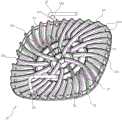
图1为本实用新型实施例中烤盘的结构示意图;Fig. 1 is the structural representation of the baking tray in the embodiment of the present utility model;
图2为本实用新型实施例中烤盘另一视角的结构示意图;Fig. 2 is the structural schematic diagram of another angle of view of the baking pan in the embodiment of the present invention;
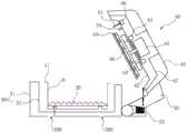
图3为本实用新型实施例中烤盘上热空气流向的示意图;Fig. 3 is the schematic diagram of the hot air flow direction on the baking pan in the embodiment of the present utility model;
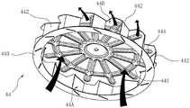
图4为本实用新型实施例中热风风叶的结构示意图;4 is a schematic structural diagram of a hot air fan blade in an embodiment of the present utility model;
图5为本实用新型实施例中热风风叶的俯视图;Fig. 5 is the top view of the hot air fan blade in the embodiment of the utility model;
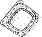
图6为本实用新型实施例中油烟过滤组件的结构示意图;6 is a schematic structural diagram of an oil fume filter assembly in an embodiment of the present invention;
图7为本实用新型实施例中油烟过滤组件的立体分解图;7 is a perspective exploded view of the oil fume filter assembly in the embodiment of the present invention;
图8为本实用新型实施例中空气炸锅的结构示意图;Fig. 8 is the structural representation of the air fryer in the embodiment of the utility model;
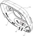
图9为本实用新型实施例中烤盘立放在空气炸锅上的结构示意图;Fig. 9 is the structural schematic diagram of the grill pan standing on the air fryer in the embodiment of the present utility model;
图10为本实用新型实施例中电机架的结构示意图;10 is a schematic structural diagram of a motor frame in an embodiment of the present invention;
图11为本实用新型实施例中空气炸锅另一视角的结构示意图(省略外壳);11 is a schematic structural diagram of the air fryer from another perspective in the embodiment of the present invention (the outer casing is omitted);
图12为本实用新型实施例中空气炸锅再一视角的结构示意图(省略外壳);12 is a schematic structural diagram of the air fryer from another perspective in the embodiment of the present invention (the outer casing is omitted);
图13为本实用新型实施例中锅盖的结构示意图;13 is a schematic structural diagram of a pot cover in an embodiment of the present invention;
图14为本实用新型实施例中锅盖的立体分解图;Figure 14 is a perspective exploded view of a pot cover in an embodiment of the present invention;
图15为本实用新型实施例中上反射板的部分结构示意图;15 is a schematic diagram of a partial structure of an upper reflector in an embodiment of the present invention;
图16为本实用新型实施例中锅盖打开状态下的结构示意图;FIG. 16 is a schematic structural diagram of the open state of the pot cover in the embodiment of the present invention;
图17为本实用新型实施例中锅盖盖合状态下的外部结构示意图;17 is a schematic diagram of the external structure of the pot lid in the closed state of the embodiment of the present invention;
图18为本实用新型实施例中锅盖盖合状态下的结构示意图;Figure 18 is a schematic structural diagram of the pot lid in the closed state in the embodiment of the present invention;
图19为本实用新型实施例中微动开关打开状态下的结构示意图;19 is a schematic structural diagram of the microswitch in an open state in an embodiment of the present utility model;
图20为本实用新型实施例中微动开关闭合状态下的结构示意图。FIG. 20 is a schematic structural diagram of the micro switch in the closed state in the embodiment of the present invention.
具体实施方式Detailed ways
以下结合附图实施例对本实用新型作进一步详细描述。The present utility model will be further described in detail below with reference to the embodiments of the accompanying drawings.
本实用新型的烤盘主要应用于空气炸锅,以放置并烹饪食物。为更直观地体现出本实用新型的烤盘在空气炸锅中的安装结构及功能,本实施例结构空气炸锅的整体结构进行阐述说明,具体如下:The grill pan of the utility model is mainly applied to the air fryer to place and cook food. In order to more intuitively reflect the installation structure and function of the grill pan of the present invention in the air fryer, the overall structure of the air fryer with the structure of the present embodiment is described, and the details are as follows:
如图1~20所示,为本申请的空气炸锅的一个优选实施例,该空气炸锅包括有机座;设置在机座内的锅体10;设置在锅体10内的烤盘20。机座可以为一体式结构,也可以为具有基座和锅盖的分体式结构。本实施例中,机座为具有基座30和锅盖40的分体式结构,锅盖40的后侧铰接在基座30上能实现转动开合,上述锅体10设置在基座30内。具体如下:As shown in FIGS. 1 to 20 , which is a preferred embodiment of the air fryer of the present application, the air fryer includes a machine base; a
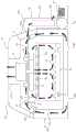
如图1~3和图9所示,上述烤盘20包括有盘状本体21,该盘状本体21上开设有漏油孔22,盘状本体21的上端面上间隔凸设有若干个凸起件23,各凸起件23的上端面整体构成用于放置食物的支撑面,相邻两个凸起件23之间形成有供热风通过的导流通道24。本实施例中,凸起件23为长条状结构,各凸起件23围绕盘状本体21的中部向外边缘呈辐射状分布;相邻两个凸起件23之间形成有供热风从盘状本体21的外边缘流向中部的上述导流通道24。为提高热风循环效率,各凸起件23沿着顺时针或逆时针方向弯曲。As shown in FIGS. 1 to 3 and FIG. 9 , the above-mentioned
为使油水能从漏油孔22漏下,防止油水堆积在盘状本体21上,盘状本体21设计为中部低、外边缘高的结构,漏油孔22设于盘状本体21的中部。具体为:漏油孔22位于盘状本体21的中心和以盘状本体21的中心为圆心的若干个同心圆周线上,导流通道24的内端与漏油孔22相对应。上述凸起件23包括有第一组凸起件231、第二组凸起件232、第三组凸起件233,第一组凸起件231以盘状本体21的中心为起点向外边缘呈辐射状分布;第二组凸起件232位于相邻两个第一组凸起件231之间并以内圈漏油孔的同心圆周线为起点向外边缘呈辐射状分布;第三组凸起件233位于相邻两个第二组凸起件232及相邻的第一、第二组凸起件之间,并以最外圈漏油孔的同心圆周线为起点向外边缘呈辐射状分布。如此,第一组凸起件231的起点对应于盘状本体21中心的漏油孔22,第二组凸起件232的起点对应于盘状本体21内圈上的漏油孔22,第三组凸起件233的起点对应于盘状本体21外圈上的漏油孔22。当然,漏油孔22不限于上述分布,也可以增加或减少漏油孔22的设置;凸起件23也同样不限于上述的分布结构。In order to allow oil and water to leak from the
为便于拿取烤盘,盘状本体21的上端面上设有提手25。该提手25有两个,并位于盘状本体21的左右两侧上;且该提手25具有能挂扣至空气炸锅上而使盘状本体21立放的钩部。提手25的具体结构为:提手整体呈倒置的L型,包括有下端支撑在盘状本体21的上端面上的立杆251、与立杆251的上端相连的横杆252,横杆252的另一端朝着盘状本体21的下侧方向延伸,与立杆251形成上述钩部。In order to facilitate taking the baking tray, a
为使烹饪完后烤盘20能实现立放,机座的上部设有能支撑提手25以使烤盘20立放的支架51。该支架51有两个并左右间隔设置在机座的后侧上;为了与提手25相配合,便于提手挂扣,支架51为凸设在机座上的凸耳。且为了进一步提高支撑强度,并收集烤盘20立放时沥下来的油水,机座的底部上设有用于支撑烤盘20并收集烤盘20上的油水的集油槽52。如此,烤盘20上的提手25能挂扣在支架51上使烤盘20立放,立放状态下烤盘20的底部支撑在集油槽52上,油水能沿着烤盘20流至集油槽52内,实现烤盘20上油水的收集,提高使用卫生。In order to make the
如图13、14、16、18所示,上述锅盖40包括有具有第一进风口41A的外壳41;设置在外壳41内的上反射板42;对应第一进风口41A设于上反射板42的上方的冷风风叶43;设于上反射板42的下方的热风风叶44;设于上反射板42的上方的驱动电机45,其输出轴依次穿过冷风风叶43、上反射板42后与热风风叶44相连;设于热风风叶44的下方的加热件46和电机架47。上述热风风叶44、加热件46和驱动电机45组成能产生热风的热风装置,冷风风叶43和驱动电机45组成能产生冷风的冷风装置。As shown in FIGS. 13 , 14 , 16 and 18 , the above-mentioned
其中,电机架47设置在上放射板42的上方,用于支撑驱动电机45;电机架47的下部与上反射板42的外边沿相连后横置在外壳41内,将外壳41的腔体上、下分隔;电机架47与上反射板42之间形成有空腔,冷风风叶43(冷风风叶43选用常规的风叶结构)设于该空腔内;电机架47的下部或/和上反射板42的外边沿上开设有供冷风流出锅盖的第二通风口47C。The
电机架47的具体结构为:包括内部中空的机架本体470,机架本体470的顶部开设有用于安装驱动电机45的安装孔471,该安装孔471与驱动电机45之间形成有供外界的冷空气进入的第二进风口47A,该第二进风口47A与第一进风口41A相对并与机架本体470的内部相连通;该安装孔471外侧的机架本体470上开设有若干个与机架本体470的内部相连通的第一通风口47B,以供冷风流向外壳41。本实施中机架本体470整体呈倒扣的碗状(机架本体470倒扣在上放射板上42形成上述空腔),第一通风口47B沿着机架本体470的侧壁周向间隔分布。机架本体470的下边沿成型有向外凸的支撑环472,该支撑环472上开设有若干个上述第二通风口47C,第二通风口47C沿着支撑环472周向分布。机架本体470的顶部向上凸设有凸起座473,该凸起座473上、下贯通形成上述安装孔471,用于容置驱动电机45,驱动电机45通过一连接件连接在安装孔471内。具体请参见图10、11、12。The specific structure of the
本实施例中,为提高热风循环效率,还包括有下反射板48,该下反射板48与上反射板42相连并设于热风风叶44和加热件46(本实施例中加热件46选用加热管)之间,该下反射板48上开设有与热风风叶44的入风口44A相对的通孔480。下反射板48与上反射板42的连接结构为:下反射板48的侧壁上通过至少三片连接片481与上反射板42相连,连接片481的两端均通过螺钉与上、下反射板相连;本实施例中连接片481有四片,并沿着下反射板48的侧壁周向间隔分布。且为了进一步聚拢热风气流,该下反射板48包括有面板和沿着面板的外边沿向下弯折的侧壁,上述通孔480设于下反射板48的面板上,连接片480连接在下反射板48的侧壁上。In this embodiment, in order to improve the hot air circulation efficiency, a
其中,如图4、5所示,热风风叶44包括有与驱动电机45的输出轴相连的转盘441和若干个叶片442(本实施例中叶片442与转盘441为一体连接件,当然也可分别单独制作,然后通过后续工艺将两者连接),叶片442向下凸设在转盘441的下端面上并环绕转盘441的边缘周向间隔设置,各叶片442沿着转盘441的旋转方向倾斜设置,相邻两个叶片442之间形成能使通过的气流旋转的出风口44B,转盘441的下端面与各叶片442之间形成供气流进入的入风口44A。为提高入风口44A的进风效率和出风口44B的出风效率,热风风叶44还包括有导风圈443,该导风圈443与各叶片442的下端部相连。其中,叶片442的数量为至少10片,本实施例中为13片,各叶片442与转盘441的径向呈20~80度倾斜设置,本实施例中倾斜角度A为49.53度。为提高转盘441的强度,转盘441的端面上设有加强筋444。Among them, as shown in FIGS. 4 and 5 , the
为实现油烟过滤,上述锅盖40还包括有用于过滤油烟的油烟过滤组件49,如图6、7、13、14、16、18所示,该油烟过滤组件49设置在加热件46的下方并与下反射板48相连(即设于热风风叶44的入风口44A下方)。其中,油烟过滤组件49包括有能连接到下反射板48上的支架491和设于支架491上的过滤层492,过滤层492有至少两层并上下间隔分布在支架491上,相邻两层过滤层492之间具有供气流流过的空间。还包括有用于防止相邻两层过滤层492相互贴合的支撑件493,该支撑件493与支架491相连并位于相邻两层过滤层492之间的空间内。In order to achieve oil fume filtering, the above-mentioned
具体为:支撑件493为横置在上述空间内的支撑条,支撑条的端部与支架491相连接。支架491整体呈环形的边框结构,支架491的外侧壁上设有能拆卸式地连接到空气炸锅上的连接件。本实施例中,该连接件包括有能插接到空气炸锅上的舌片494(本实施例中下反射板48的侧壁上设有插孔482,舌片494插接到该插孔482中),该舌片494连接在支架491一侧的外侧壁上;支架491另一侧的外侧壁上设有与空气炸锅上的卡钩483配合的卡槽495(本实施例中卡钩483设置在下放射板48的侧壁上)。卡槽495沿着支架491的外侧壁周向延伸。为便于拿取,油烟过滤组件49还包括有把手496,该把手496卡接在卡槽495内。本实施中,过滤层492有两层,并分别与支架491的上、下边沿相连接。支撑件493整体呈十字形结构,当然也可选用其他结构的支撑件,只要能实现支撑过滤层492,并不阻碍热风流动均可。通过设置油烟过滤组件49,能过滤掉一部风的油烟,防止油烟黏附在加热件46、热风风叶44上而影响使用。Specifically, the
本实施例中,为便于锅盖40的开合,空气炸锅还包括有转动机构50,锅盖40通过转动机构50铰接在基座30上,上述支架51设于转动机构50的左右两侧,上述集油槽52设于转动机构50与基座30的铰接处。其中,转动机构50包括有转板53和转轴54,转板53的上端与锅盖40的后侧相连接,下端通过转轴54与基座30转动连接;集油槽52设于转轴54上并与基座30相连接。上述转板53内部开设有用于容置线路板的空间530,且转板53上开设有与该空间530相连通的散热孔。具体为:转板53上开设有与该空间530相连通的第四进风口53A和第四通风口53B,第四进风口53A与上述第一通风口47B相连通,第四通风口53B与外界相连通。In this embodiment, in order to facilitate the opening and closing of the
为实现锅盖40打开后黏附在锅盖40上的油水不会随处滴溅,锅盖40上与锅体10相对的工作面(即上述上反射板42的工作面)上设有在锅盖40打开后能将工作面上的油水导流至锅盖40后侧的导油通道,在锅盖40打开后上述集油槽52位于该导油通道的出口的下方。具体为:上反射板42的工作面上开设有沿着工作面的边沿从工作面的左、右两侧相对地向后侧延伸的第一导油槽421、第二导油槽422,第一导油槽421、第二导油槽422组成上述导油通道,第一导油槽421后侧的端部与第二导油槽422后侧的端部之间留有间隔420,该间隔420为导油通道的出口。In order to prevent the oil and water adhering to the
本实施例中,上反射板42整体呈倒扣的碗状,上反射板42的内壁面为上述的工作面。上反射板42的边沿设有向外凸的连接环423,该连接环423通过螺钉与电机架47相连接,以实现电机架47与上反射板42将外壳41的腔体上、下分隔。且上反射板42包括内、外套设的第一单元反射板424、第二单元反射板425,第一、第二单元反射板之间通过上述连接环423相连。如此,锅盖40打开后,锅盖40上的油水能沿着第一、第二导油槽流至出口,然后汇集至集油槽52内,实现油水的收集,进一步提高使用卫生。为了排出工作过程中产生的油烟,在外壳41上开设有第一排烟口411,在上反射板42上开设有第二排烟口426,第一排烟口411与第二排烟口426之间通过排烟管427连接(排烟管427的底部连接在上反射板42上并与第二排烟口相连通,顶部穿过第一排烟口411,以将油烟排出)。如此,产生的油烟能通过排烟管427排出至外界。本实施例中,排烟管427倾斜设置。In this embodiment, the
如图18所示,本实施例中热风循环的路径为:从热风风叶44的出风口44B出来的热风沿着锅盖40进入锅体10内,并沿着锅体10的内壁流至烤盘20,从烤盘20的边缘沿着导流通道24流向烤盘20的中部,并在热风风叶44的入风口44A负压的作用下,烤盘20中部的热风依次经过油烟过滤组件49、加热件46后吸入热风风叶44,再由热风风叶44的出风口44B吹出,完成一个完整的热风循环。当然也会有部分的热风沿着锅体10内壁流至烤盘20的下方,并从烤盘20中部的漏油孔22被向上吸入热风风叶44内。故而,锅体10与上反射板42的工作面之间形成供热风循环的热循环空间。As shown in FIG. 18 , the hot air circulation path in this embodiment is as follows: the hot air from the
热风循环会使基座30的温度升高,为实现基座30散热,本实施例中的基座30包括有外壁31和内壁32,且基座30的外壁31与内壁32之间为中空结构,基座30的上端面上对应第二通风口47C开设有第三进风口30A,基座30的外壁31上开设有与第三进风口30A相连通的第三通风口30B(当锅盖40盖合在基座30上时,电机架47上的支撑环472的下端面与基座30的上端面接触配合);外壳41、上反射板42的上端面、电机架47与基座30之间形成供冷风循环的冷循环空间;本实施例中该第三通风口30B设于基座30的底部和后侧,一部分冷风从基座30底部流出进入外界,另一部分冷风从基座30的后侧流出,从基座30后侧流出的冷风能对上述转板53进行进一步冷却降温。The hot air circulation will increase the temperature of the
故而,本实施例中冷风循环路径为:外界空气沿着外壳41的第一进风口41A、电机架47的第二进风口47A吸入电机架47内后,在冷风风叶43的作用下从第一通风口47B吹出,且从第一通风口47B吹出的一部分冷风从第四进风口53A进入转板53内,冷却转板53内的线路板后从第四通风口53B流出,吹向外界;另一部分冷风从电机架47的第二通风口47C吹出并从基座30的第三进风口30A进入基座30内部,以冷却基座30,防止基座过热,然后从第三通风口30B出。Therefore, in this embodiment, the cold air circulation path is as follows: after the outside air is sucked into the
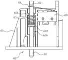
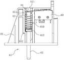
在使用时,为避免出现未放置锅体10就进行烹饪的情况出现,还设有用于检测锅体10是否放入的微动开关60和能触动该微动开关60的传动件61。如图18、19、20所示,该微动开关60为常开式结构,空气炸锅仅在微动开关60打开的状态下工作,锅体10上设有与传动件61配合的触发部,该触发部在锅体10位于机座内的状态下作用在传动件61上使微动开关60仍处于打开状态,该传动件61在锅体10离开机座的状态下复位并驱使微动开关60闭合。由于本实施例的机座包括有基座30和锅盖40,故而,为同时检测锅盖40是否盖合,上述微动开关60和传动件61设置在锅盖40上(本实施中,微动开关60和传动件61设置在上述电机架47上),上述触发部在锅体10位于基座30内且锅盖40盖合的状态下作用在传动件61上使微动开关60仍处于打开状态,该传动件61在锅盖40打开或/和锅体10离开基座30的状态下复位并驱使微动开关60闭合。为使锅体10能和传动件61稳定地配合,锅体10的上边沿上设有外翻边11,触发部位于该外翻边11上,以增大了锅体10的接触面。In use, in order to avoid the situation of cooking without placing the
上述传动件61的具体结构为:传动件61包括有竖向设置的传动杆62、套设在传动杆62上使传动杆始终具有向下移动的趋势的弹簧63,该传动杆62的下端与上述触发部配合而脱离或作用在触发部上,上端与微动开关60的触点64配合而闭合或脱离触点64;在传动杆62的下端作用在触发部上的状态下,传动杆62向上移动,传动杆62的上端脱离微动开关60的触点64;在传动杆62的下端脱离触发部的状态下,传动杆62在弹簧63的作用下向下移动、复位,传动杆62的上端与微动开关60的触点64接触并驱动触点64闭合。(本实施例中,传动杆62的上端凸设有台阶621,该台阶621位于微动开关60的触点64上方,当传动杆62下移时,台阶621与微动开关60的触点64接触,并驱动触点64闭合;当传动杆62上移时,台阶621与微动开关60的触点64脱离,触点64处于打开状态)。为使传动杆62能稳定工作,该传动件61还包括有设置在锅盖40的电机架47上的支撑座65,该支撑座65的侧面上竖向设有导向槽650,传动杆62设置在该导向槽650内并能沿着导向槽650上下移动;微动开关60设置在该支撑座65的上部。为限制传动杆62的移动距离,导向槽650的上部设有用于限制传动杆62最高位置的第一台阶651,下部设有用于限制传动杆62最低位置的第二台阶652,传动杆42上设有与第一、第二台阶配合的凸缘622。上述弹簧63套设在传动杆62上后位于导向槽650内,弹簧63的下端支撑在凸缘622上,上端能抵接在第一台阶651上,弹簧63在传动杆62向上移动的过程中受到压缩而使传动杆62始终具有向下移动的趋势。如此,当传动杆62的下端脱离触发部时(即锅体10未放入基座30或/和锅盖40未盖合),传动杆62在弹簧63的作用下下移,传动杆62的上端驱动微动开关60闭合,微动开关60闭合时,空气炸锅不能执行烹饪工作。当传动杆62的下端抵接作用在触发部上时(即锅体10放入基座30且锅盖40盖合),传动杆62上移,传动杆62的上端远离微动开关60,微动开关60处于常开状态,空气炸锅能执行烹饪工作。The specific structure of the above-mentioned
为防止锅盖40在盖合过程中出现卡死或盖不严的情况,锅盖40与基座30的盖合面为向后下侧倾斜的倾斜度B≤30度的斜面,具体请参见图17。且由于驱动电机45、加热件46、热风风叶44等部件均设置在锅盖40内,使得锅盖40较重,为避免锅盖40打开时意外夹手,锅盖40与基座30的转动连接处设有扭簧,即上述转动机构50的转轴54上设有扭簧,以使锅盖40打开后能在扭簧作用下缓慢打开。如图16、18所示,为检测锅内的温度,锅盖40上还设有检温装置70,检温装置70可参考现有技术,在此不做赘述。In order to prevent the
Claims (8)
Priority Applications (1)
| Application Number | Priority Date | Filing Date | Title |
|---|---|---|---|
| CN201920956688.9UCN211355052U (en) | 2019-06-24 | 2019-06-24 | Baking tray and air fryer with same |
Applications Claiming Priority (1)
| Application Number | Priority Date | Filing Date | Title |
|---|---|---|---|
| CN201920956688.9UCN211355052U (en) | 2019-06-24 | 2019-06-24 | Baking tray and air fryer with same |
Publications (1)
| Publication Number | Publication Date |
|---|---|
| CN211355052Utrue CN211355052U (en) | 2020-08-28 |
Family
ID=72157974
Family Applications (1)
| Application Number | Title | Priority Date | Filing Date |
|---|---|---|---|
| CN201920956688.9UWithdrawn - After IssueCN211355052U (en) | 2019-06-24 | 2019-06-24 | Baking tray and air fryer with same |
Country Status (1)
| Country | Link |
|---|---|
| CN (1) | CN211355052U (en) |
Cited By (2)
| Publication number | Priority date | Publication date | Assignee | Title |
|---|---|---|---|---|
| CN110151002A (en)* | 2019-06-24 | 2019-08-23 | 郭鑫 | A baking pan and an air fryer with the baking pan |
| US12349837B1 (en)* | 2022-12-11 | 2025-07-08 | Ghada Wadi | Air fryer system |
- 2019
- 2019-06-24CNCN201920956688.9Upatent/CN211355052U/ennot_activeWithdrawn - After Issue
Cited By (2)
| Publication number | Priority date | Publication date | Assignee | Title |
|---|---|---|---|---|
| CN110151002A (en)* | 2019-06-24 | 2019-08-23 | 郭鑫 | A baking pan and an air fryer with the baking pan |
| US12349837B1 (en)* | 2022-12-11 | 2025-07-08 | Ghada Wadi | Air fryer system |
Similar Documents
| Publication | Publication Date | Title |
|---|---|---|
| US5699722A (en) | Rapid cooking device | |
| US5513558A (en) | Rapid cooking device | |
| US5165328A (en) | Expandable countertop oven | |
| US4817509A (en) | Air Fryer | |
| CN110101316A (en) | A kind of air fryer | |
| CN210902654U (en) | Pot cover and air fryer with same | |
| CN210276928U (en) | a multifunctional oven | |
| CN110151002A (en) | A baking pan and an air fryer with the baking pan | |
| CN110101317A (en) | A kind of pot cover and the air fryer with the pot cover | |
| CN214549018U (en) | Air fryer with uniform heating | |
| CN211355052U (en) | Baking tray and air fryer with same | |
| CN210446767U (en) | Oil fume filter assembly and air fryer with the oil fume filter assembly | |
| CN210446768U (en) | Air frying pan | |
| AU630338B2 (en) | Hot air cooker | |
| CN213524863U (en) | Cooking utensil | |
| CN210446774U (en) | Air frying pan | |
| CN210446771U (en) | Air frying pan | |
| CN214841068U (en) | An all-in-one frying machine with a new oil receiving box | |
| CN210041493U (en) | Motor frame and air fryer with same | |
| JPH04500761A (en) | hot air cooker | |
| CN216724257U (en) | A separate air fryer | |
| CN114680660B (en) | Frying and baking type multifunctional food processor | |
| CN213993310U (en) | Air frying pan with skewer baking function | |
| CN210611930U (en) | A kind of fan blade and air fryer with the fan blade | |
| CN210446772U (en) | an air fryer |
Legal Events
| Date | Code | Title | Description |
|---|---|---|---|
| GR01 | Patent grant | ||
| GR01 | Patent grant | ||
| EE01 | Entry into force of recordation of patent licensing contract | Assignee:NINGBO JUMENG INTELLIGENT TECHNOLOGY Co.,Ltd. Assignor:YUEDA ELECTRONIC TECHNOLOGY Co.,Ltd. Contract record no.:X2021330000116 Denomination of utility model:The utility model relates to a baking pan and an air fryer with the baking pan Granted publication date:20200828 License type:Common License Record date:20210828 | |
| EE01 | Entry into force of recordation of patent licensing contract | ||
| AV01 | Patent right actively abandoned | Granted publication date:20200828 Effective date of abandoning:20241024 | |
| AV01 | Patent right actively abandoned | Granted publication date:20200828 Effective date of abandoning:20241024 | |
| AV01 | Patent right actively abandoned | ||
| AV01 | Patent right actively abandoned |