CN211327993U - Abdomen building machine with adjustable forearm is stably placed type - Google Patents
Abdomen building machine with adjustable forearm is stably placed typeDownload PDFInfo
- Publication number
- CN211327993U CN211327993UCN201922291702.0UCN201922291702UCN211327993UCN 211327993 UCN211327993 UCN 211327993UCN 201922291702 UCN201922291702 UCN 201922291702UCN 211327993 UCN211327993 UCN 211327993U
- Authority
- CN
- China
- Prior art keywords
- forearm
- plate
- arc
- mounting
- stably
- Prior art date
- Legal status (The legal status is an assumption and is not a legal conclusion. Google has not performed a legal analysis and makes no representation as to the accuracy of the status listed.)
- Expired - Fee Related
Links
- 210000000245forearmAnatomy0.000titleclaimsabstractdescription83
- 210000001015abdomenAnatomy0.000titleabstract2
- 210000003127kneeAnatomy0.000claimsabstractdescription19
- 210000002414legAnatomy0.000claimsabstractdescription8
- 230000003187abdominal effectEffects0.000claimsdescription17
- 238000005728strengtheningMethods0.000claimsdescription6
- 210000003489abdominal muscleAnatomy0.000description9
- 210000001624hipAnatomy0.000description8
- 210000001217buttockAnatomy0.000description3
- 230000000694effectsEffects0.000description2
- 210000004705lumbosacral regionAnatomy0.000description2
- 238000000034methodMethods0.000description2
- 210000004197pelvisAnatomy0.000description2
- 210000001139rectus abdominisAnatomy0.000description2
- 208000008035Back PainDiseases0.000description1
- 208000008930Low Back PainDiseases0.000description1
- 230000009286beneficial effectEffects0.000description1
- 210000002808connective tissueAnatomy0.000description1
- 230000008774maternal effectEffects0.000description1
- 238000012986modificationMethods0.000description1
- 230000004048modificationEffects0.000description1
- 230000032696parturitionEffects0.000description1
- 210000002784stomachAnatomy0.000description1
Images


Landscapes
- Orthopedics, Nursing, And Contraception (AREA)
Abstract
Description
Translated fromChinese技术领域technical field
本实用新型涉及健腹机技术领域,具体为一种前臂稳定放置型可调式健腹机。The utility model relates to the technical field of abdominal strengthening machines, in particular to an adjustable abdominal strengthening machine of a stable placement type forearm.
背景技术Background technique
腹肌是人体缔结组织中的重要组成部分,包括腹外斜肌、腹直肌、腹内斜肌和腹横肌。当腹肌收缩时,可以使躯干发生旋转和弯曲,并可以防止骨盆前倾。腹部肌肉对于腰椎的活动和稳定性也有着非常重要的作用,可以控制骨盆和脊柱的活动。软弱无力的腹肌可能导致腰椎生理弯曲增加和骨盆前倾,并增加腰背痛的概率。因此,女性产后腹肌锻炼显得尤为重要,现有腹肌训练的方法一般为借助健腹机锻炼,具有良好的锻炼效果。The abdominal muscles are an important part of the connective tissue in the human body, including the external oblique, rectus abdominis, internal oblique and transverse abdominis. When the abdominal muscles contract, they allow the torso to rotate and flex and prevent the pelvis from tilting forward. The abdominal muscles also play a very important role in the mobility and stability of the lumbar spine, controlling the movement of the pelvis and spine. Weak abdominal muscles may lead to increased physical curvature of the lumbar spine and anterior pelvic tilt, and increase the probability of low back pain. Therefore, postpartum abdominal muscle exercise for women is particularly important. The existing abdominal muscle training method is generally exercising with the help of an abdominal fitness machine, which has a good exercise effect.
另一方面,产妇分娩后,腹部腹直肌和皮肤出现松垮的现象,2016年二胎政策的开放,现阶段进行产后锻炼以期恢复健康完美的身材的产妇越来越多,尤其是初产妇,其中腹肌锻炼尤为重要。但是,目前市面上的健腹机在产妇使用的情况下存在如下缺点:无法稳定的放置手臂、存在安全隐患;无法调节前臂的倾斜角度,不能灵活适应产妇的使用。On the other hand, after giving birth, the rectus abdominis and skin of the puerperae become loose. With the opening of the two-child policy in 2016, more and more mothers, especially primiparas, are doing postpartum exercise in order to restore a healthy and perfect figure. , of which abdominal muscle exercise is particularly important. However, the abdominal fitness machines currently on the market have the following disadvantages when used by puerperae: the arm cannot be placed stably, and there is a potential safety hazard;
发明内容SUMMARY OF THE INVENTION
本实用新型的目的是为了提供一种手臂稳定放置型可调式健腹机,使用时,用双手握住握柄,并把前臂放置在前臂撑板的U型结构内,以解决无法稳定的放置前臂、存在安全隐患的问题;通过调节装置可以调节前臂撑板的倾斜角度和前臂撑板相对于横梁的位置,以解决无法调节前臂的倾斜角度,不能灵活适应产妇使用的问题。The purpose of the utility model is to provide an adjustable abdominal strengthening machine with stable arm placement. When using, hold the handle with both hands, and place the forearm in the U-shaped structure of the forearm support plate, so as to solve the problem of unstable placement. Forearm, the problem of potential safety hazards; through the adjustment device, the inclination angle of the forearm support plate and the position of the forearm support plate relative to the beam can be adjusted, so as to solve the problem that the inclination angle of the forearm cannot be adjusted and can not be flexibly adapted to the use of puerperae.
为了实现上述发明目的,本实用新型采用了以下技术方案:一种前臂稳定放置型可调式健腹机,包括互相连接设置的滑轨和支腿,所述滑轨一端设有后垫脚,所述支腿底端设有前垫脚,所述滑轨上设有滑块,所述滑块顶面设有膝盖支撑组件;In order to achieve the above purpose of the invention, the utility model adopts the following technical solutions: a forearm stably placed adjustable abdominal fitness machine, comprising a sliding rail and a supporting leg that are connected to each other, one end of the sliding rail is provided with a rear foot, and the The bottom end of the outrigger is provided with a front foot, the sliding rail is provided with a sliding block, and the top surface of the sliding block is provided with a knee support assembly;
所述支腿顶端设有横梁,所述横梁两端均垂直设有握柄,所述握柄和横梁之间设有前臂支撑装置,所述前臂支撑装置能够沿横梁滑动和绕横梁转动,所述前臂支撑装置还能够稳定放置前臂。The top of the outrigger is provided with a beam, both ends of the beam are vertically provided with handles, and a forearm support device is arranged between the handle and the beam, and the forearm support device can slide along the beam and rotate around the beam, so The forearm support device can also place the forearm stably.
优选的,所述前臂支撑装置包括前臂撑板和调节装置,所述横梁两端均可拆卸的设有安装座,所述前臂撑板转动设置在安装座顶面上,所述前臂撑板包括底板和侧板,且底板和侧板形成U型结构,所述U型结构用于稳定放置前臂,所述前臂撑板前端转动设有安装块,所述横梁中间位置处设有固定套,所述调节装置活动设置在安装块和固定套之间。Preferably, the forearm support device includes a forearm support plate and an adjustment device, a mounting seat is detachably provided at both ends of the beam, the forearm support plate is rotatably arranged on the top surface of the mounting seat, and the forearm support plate includes The bottom plate and the side plate, and the bottom plate and the side plate form a U-shaped structure, the U-shaped structure is used to place the forearm stably, the front end of the forearm support plate is rotated with a mounting block, and the middle position of the beam is provided with a fixed sleeve, so The adjusting device is movably arranged between the mounting block and the fixing sleeve.
优选的,所述调节装置包括调节连杆和推杆,所述推杆滑动设置在固定套内,所述固定套和推杆之间设有定位插件,所述调节连杆转动设置在推杆和安装块之间,且调节连杆能够绕握柄转动。Preferably, the adjustment device includes an adjustment link and a push rod, the push rod is slidably arranged in a fixed sleeve, a positioning insert is provided between the fixed sleeve and the push rod, and the adjustment link is rotatably arranged on the push rod and the mounting block, and the adjustment link can rotate around the handle.
优选的,还包括固定在握柄上的安装件,所述安装件具有通槽结构,所述调节连杆贯穿通槽结构并和安装件转动连接,所述调节连杆采用折线型结构,且调节连杆的内端朝向推杆内折。Preferably, it also includes a mounting piece fixed on the handle, the mounting piece has a through-slot structure, the adjusting link penetrates through the through-slot structure and is rotatably connected with the mounting piece, the adjusting link adopts a zigzag structure, and adjusts The inner end of the connecting rod is folded inward toward the push rod.
优选的,所述安装座卡设在横梁上,所述安装座底端具有开口结构,所述开口结构上设有锁紧件。Preferably, the mounting seat is clamped on the beam, the bottom end of the mounting seat has an opening structure, and the opening structure is provided with a locking member.
优选的,所述膝盖支撑组件包括互相垂直设置的弧形底板和立板,所述弧形底板固定设置在滑块的顶端上,所述弧形底板和立板形成弧形凹槽,弧形凹槽用于稳定放置膝盖。Preferably, the knee support assembly includes an arc-shaped bottom plate and a vertical plate arranged perpendicularly to each other, the arc-shaped bottom plate is fixedly arranged on the top end of the slider, and the arc-shaped bottom plate and the vertical plate form an arc-shaped groove, and the arc-shaped bottom plate and the vertical plate form an arc-shaped groove. The grooves are used for stable placement of the knee.
优选的,所述后垫脚顶端中央位置处通过安装杆设有臀护板,所述臀护板采用弧形结构。Preferably, a hip guard is provided at the central position of the top end of the rear foot pad through a mounting rod, and the hip guard adopts an arc structure.
与现有技术相比,采用了上述技术方案的前臂稳定放置型可调式健腹机,具有如下有益效果:使用时,用双手握住握柄,并把前臂放置在前臂撑板的U型结构内,可以稳定的放置前臂、消除安全隐患;通过调节装置可以调节前臂撑板的倾斜角度和前臂撑板相对于横梁的位置,进而调节前臂的倾斜角度,灵活的适应产妇使用。Compared with the prior art, the forearm stable placement type adjustable abdominal fitness machine that adopts the above technical solution has the following beneficial effects: when using, hold the handle with both hands, and place the forearm on the U-shaped structure of the forearm support plate Inside, the forearm can be placed stably, eliminating potential safety hazards; through the adjustment device, the inclination angle of the forearm support plate and the position of the forearm support plate relative to the beam can be adjusted, and then the inclination angle of the forearm can be adjusted to flexibly adapt to the use of puerperae.
附图说明Description of drawings
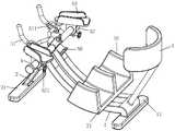
图1为本实用新型前臂稳定放置型可调式健腹机的立体图;Fig. 1 is the perspective view of the utility model forearm stable placement type adjustable stomach machine;
图2为实施例的主视图;Fig. 2 is the front view of embodiment;
图3为实施例的俯视图;3 is a top view of the embodiment;
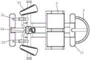
图4为实施例中前臂支撑装置的立体图;4 is a perspective view of a forearm support device in an embodiment;
图5为实施例中前臂支撑装置的主视图;5 is a front view of the forearm support device in the embodiment;
图6为实施例中前臂支撑装置的俯视图;Fig. 6 is the top view of the forearm support device in the embodiment;
图7为实施例中前臂支撑装置的俯视图(前臂撑板调节角度后)。FIG. 7 is a top view of the forearm support device in the embodiment (after the angle of the forearm brace is adjusted).
附图标记:滑轨1、后垫脚11、支腿2、前垫脚21、膝盖支撑组件3、弧形底板31、立板32、臀护板4、横梁5、握柄51、安装件511、安装座52、锁紧件521、前臂撑板53、调节连杆54、固定套55、推杆56、定位插件57、安装块58、滑块6。Reference numerals:
具体实施方式Detailed ways
下面结合附图对本实用新型做进一步描述。The present utility model will be further described below in conjunction with the accompanying drawings.
如图1-3所示的前臂稳定放置型可调式健腹机,包括互相连接设置的滑轨1和支腿2,滑轨1一端设有后垫脚11,后垫脚11顶端中央位置处通过安装杆设有臀护板4,臀护板4采用弧形结构,支腿2底端设有前垫脚21;后垫脚11支撑起滑轨1的后端,同时前垫脚21支撑起支腿2的底端,支腿2和滑轨1共同组成整个健腹机的基体结构,其中,后垫脚11和前垫脚21优选的采用长条形板体,并且后垫脚11、前垫脚21均和支腿2、滑轨1所在的平面互相垂直设置,以稳定的支撑起整个健腹机,另外,后垫脚11通过安装杆安装有臀护板4,臀护板4用于防护产妇的臀部,其中,臀护板4采用弧形结构的设计,可以增加臀部的防护面积,确保产妇安全使用。As shown in Figure 1-3, the forearm stable adjustable abdominal fitness machine includes a
如图1-3所示,滑轨1上设有滑块6,滑块6顶面设有膝盖支撑组件3,膝盖支撑组件3包括互相垂直设置的弧形底板31和立板32,弧形底板31固定设置在滑块6的顶端上,弧形底板31和立板32形成弧形凹槽,弧形凹槽用于稳定放置膝盖;使用时,产妇把膝盖放置在膝盖支撑组件3上,并通过腹肌和腿部给膝盖支撑组件3施加沿滑轨1方向的力,在滑块6和滑轨1滑动配合的作用下,膝盖带动滑块6沿着滑轨1滑动,其中,滑轨1和滑块6配合的一段采用弧形结构,以利于滑块6滑动的同时确保产妇臀部位置不发生改变,确保腹肌的锻炼效果,具体的,产妇把膝盖放置在弧形底板31和立板32形成的弧形凹槽内,弧形底板31从底部托住膝盖,同时,立板32可从侧面挡住膝盖,确保产妇锻炼的过程中膝盖不会滑落,消除膝盖滑落的安全隐患。As shown in Figures 1-3, the
如图1、4-7所示,支腿2顶端设有横梁5,横梁5两端均垂直设有握柄51,握柄51和横梁5之间设有前臂支撑装置,前臂支撑装置能够沿横梁5滑动和绕横梁5转动,前臂支撑装置还能够稳定放置前臂,前臂支撑装置包括前臂撑板53和调节装置,横梁5两端均可拆卸的设有安装座52,安装座52卡设在横梁5上,安装座52底端具有开口结构,开口结构上设有锁紧件521,前臂撑板53转动设置在安装座52顶面上,前臂撑板53包括底板和侧板,且底板和侧板形成U型结构,U型结构用于稳定放置前臂,前臂撑板53前端转动设有安装块58,横梁5中间位置处设有固定套55;使用时,产妇用双手握住握柄51,握柄51外围可以设置海绵套以改善产妇的手感,另外,安装座52通过锁紧件521卡固在横梁5上,当松开锁紧件521后,安装座52底端的开口结构略微张开,可以沿横梁5的方向移动安装座52,进而改变前臂撑板53相对于横梁5的位置,然后通过锁紧件521锁紧即可,产妇可以调节前臂撑板53的位置以适应自身前臂的长度,使用起来更加灵活,同时,前臂撑板53可相对于安装座52旋转以适应前臂撑板53的转动,使用时,把前臂放置在前臂撑板53上,底板可以从底部托起前臂,同时侧板从侧面挡住前臂,进而,U型结构可以稳定放置前臂,消除安全隐患,最后,前臂撑板53前端转动设有安装块58的设计,可以适应前臂撑板53的转动。As shown in Figures 1 and 4-7, the top of the outrigger 2 is provided with a
如图1、4-7所示,调节装置活动设置在安装块58和固定套55之间,调节装置包括调节连杆54和推杆56,推杆56滑动设置在固定套55内,固定套55和推杆56之间设有定位插件57,调节连杆54转动设置在推杆56和安装块58之间,且调节连杆54能够绕握柄51转动,还包括固定在握柄51上的安装件511,安装件511具有通槽结构,调节连杆54贯穿通槽结构并和安装件511转动连接,调节连杆54采用折线型结构,且调节连杆54的内端朝向推杆56内折;朝着固定套55的方向推动推杆56,然后通过定位插件57定位推杆56的位置,具体的,推杆56顶面开设有多个定位插孔,把定位插件57的底端插入到定位插孔内即可定位推杆56,推杆56前端的移动,带动调节连杆54内端移动,在调节连杆54转动设置在安装件511内的作用下,使得调节连杆54发生摆动,同时调节连杆54的两端分别相对于推杆56、安装块58转动,调节连杆54的外端通过安装块58带动前臂撑板53的前端摆动,进而调节前臂撑板53的倾斜角度,可以灵活的适应产妇的锻炼需求,另外,调节连杆54的内端朝向推杆56内折的设计,可以缩短推杆56的长度,节省材料。As shown in Figures 1, 4-7, the adjusting device is movably arranged between the
以上所述是本实用新型的优选实施方式,对于本领域的普通技术人员来说不脱离本实用新型原理的前提下,还可以做出若干变型和改进,这些也应视为本实用新型的保护范围。The above are the preferred embodiments of the present invention. For those of ordinary skill in the art, some modifications and improvements can be made without departing from the principles of the present invention. These should also be regarded as the protection of the present invention. scope.
Claims (7)
Translated fromChinesePriority Applications (1)
| Application Number | Priority Date | Filing Date | Title |
|---|---|---|---|
| CN201922291702.0UCN211327993U (en) | 2019-12-18 | 2019-12-18 | Abdomen building machine with adjustable forearm is stably placed type |
Applications Claiming Priority (1)
| Application Number | Priority Date | Filing Date | Title |
|---|---|---|---|
| CN201922291702.0UCN211327993U (en) | 2019-12-18 | 2019-12-18 | Abdomen building machine with adjustable forearm is stably placed type |
Publications (1)
| Publication Number | Publication Date |
|---|---|
| CN211327993Utrue CN211327993U (en) | 2020-08-25 |
Family
ID=72090588
Family Applications (1)
| Application Number | Title | Priority Date | Filing Date |
|---|---|---|---|
| CN201922291702.0UExpired - Fee RelatedCN211327993U (en) | 2019-12-18 | 2019-12-18 | Abdomen building machine with adjustable forearm is stably placed type |
Country Status (1)
| Country | Link |
|---|---|
| CN (1) | CN211327993U (en) |
Cited By (1)
| Publication number | Priority date | Publication date | Assignee | Title |
|---|---|---|---|---|
| CN112516528A (en)* | 2020-12-02 | 2021-03-19 | 湖南文理学院 | Sports specialty belly body-building device |
- 2019
- 2019-12-18CNCN201922291702.0Upatent/CN211327993U/ennot_activeExpired - Fee Related
Cited By (1)
| Publication number | Priority date | Publication date | Assignee | Title |
|---|---|---|---|---|
| CN112516528A (en)* | 2020-12-02 | 2021-03-19 | 湖南文理学院 | Sports specialty belly body-building device |
Similar Documents
| Publication | Publication Date | Title |
|---|---|---|
| US5100131A (en) | Back muscle exercising and stretching apparatus | |
| US5106083A (en) | Exercise device with protrusion | |
| CN110327597A (en) | A kind of Multifunctional rehabilitation exercise chair | |
| CN214968409U (en) | Beach chair surgical bed for shoulder surgery | |
| CN111388264A (en) | Double-heart integrated bonesetting physiotherapy chair | |
| CN105477841B (en) | A kind of pile frame trains assistor | |
| CN213098952U (en) | Medical treatment is with shank support nursing device | |
| CN211327993U (en) | Abdomen building machine with adjustable forearm is stably placed type | |
| CN210903946U (en) | A weight loss standing frame for children's rehabilitation | |
| CN108403338A (en) | Handrail on the three-dimensional adjustable bed of self-contained unit | |
| EP0131167A2 (en) | Therapeutic device for body stretching | |
| CN110917574B (en) | Abdomen building machine for puerpera exercise | |
| CN219662194U (en) | Lumbar vertebra bone setting device | |
| CN209751568U (en) | Children rehabilitation walker for cerebral palsy | |
| CN211382476U (en) | Backrest adjustable sitting posture correction chair | |
| CN217645764U (en) | A kind of lower limb rehabilitation training device | |
| AU2021101283A4 (en) | Rehabilitation Chair for Orthopedics Department | |
| CN211485534U (en) | Ankle pump athletic training recorder | |
| CN210543175U (en) | Multifunctional rehabilitation training chair | |
| CN211326335U (en) | A multi-stage adjustable pelvic elevation device | |
| CN208990133U (en) | A kind of rehabilitation training device for lumbar spine surgery | |
| CN220142071U (en) | Back treatment auxiliary chair | |
| CN222693947U (en) | Cervical vertebra rehabilitation training device | |
| CN212214476U (en) | A kind of auxiliary device for exercising lumbar back muscles after operation | |
| CN221534238U (en) | Support for assisting children in sitting up and training after hip joint dysplasia operation |
Legal Events
| Date | Code | Title | Description |
|---|---|---|---|
| GR01 | Patent grant | ||
| GR01 | Patent grant | ||
| CF01 | Termination of patent right due to non-payment of annual fee | Granted publication date:20200825 | |
| CF01 | Termination of patent right due to non-payment of annual fee |