CN211301453U - Irrigation device for urological care - Google Patents
Irrigation device for urological careDownload PDFInfo
- Publication number
- CN211301453U CN211301453UCN201922351980.0UCN201922351980UCN211301453UCN 211301453 UCN211301453 UCN 211301453UCN 201922351980 UCN201922351980 UCN 201922351980UCN 211301453 UCN211301453 UCN 211301453U
- Authority
- CN
- China
- Prior art keywords
- fixedly connected
- storage tank
- bevel gear
- liquid
- valve body
- Prior art date
- Legal status (The legal status is an assumption and is not a legal conclusion. Google has not performed a legal analysis and makes no representation as to the accuracy of the status listed.)
- Expired - Fee Related
Links
- 238000003973irrigationMethods0.000titleclaimsabstractdescription11
- 230000002262irrigationEffects0.000titleclaimsabstractdescription11
- 239000007788liquidSubstances0.000claimsabstractdescription80
- XLYOFNOQVPJJNP-UHFFFAOYSA-NwaterSubstancesOXLYOFNOQVPJJNP-UHFFFAOYSA-N0.000claimsabstractdescription52
- 239000002699waste materialSubstances0.000claimsabstractdescription19
- 230000007246mechanismEffects0.000claimsabstractdescription14
- 230000000474nursing effectEffects0.000claimsabstractdescription12
- 238000003756stirringMethods0.000claimsdescription11
- 238000011010flushing procedureMethods0.000claimsdescription7
- 239000007921spraySubstances0.000claimsdescription4
- 238000001356surgical procedureMethods0.000claimsdescription2
- 230000002485urinary effectEffects0.000claims3
- 238000000034methodMethods0.000abstractdescription5
- 239000003814drugSubstances0.000abstractdescription4
- 239000002244precipitateSubstances0.000abstractdescription4
- 230000008569processEffects0.000abstractdescription4
- 238000010586diagramMethods0.000description5
- 238000004140cleaningMethods0.000description3
- 230000003902lesionEffects0.000description3
- 238000001556precipitationMethods0.000description3
- 230000009471actionEffects0.000description2
- POIUWJQBRNEFGX-XAMSXPGMSA-NcathelicidinChemical compoundC([C@@H](C(=O)N[C@@H](CCCNC(N)=N)C(=O)N[C@@H](CCCCN)C(=O)N[C@@H](CO)C(=O)N[C@@H](CCCCN)C(=O)N[C@@H](CCC(O)=O)C(=O)N[C@@H](CCCCN)C(=O)N[C@@H]([C@@H](C)CC)C(=O)NCC(=O)N[C@@H](CCCCN)C(=O)N[C@@H](CCC(O)=O)C(=O)N[C@@H](CC=1C=CC=CC=1)C(=O)N[C@@H](CCCCN)C(=O)N[C@@H](CCCNC(N)=N)C(=O)N[C@@H]([C@@H](C)CC)C(=O)N[C@@H](C(C)C)C(=O)N[C@@H](CCC(N)=O)C(=O)N[C@@H](CCCNC(N)=N)C(=O)N[C@@H]([C@@H](C)CC)C(=O)N[C@@H](CCCCN)C(=O)N[C@@H](CC(O)=O)C(=O)N[C@@H](CC=1C=CC=CC=1)C(=O)N[C@@H](CC(C)C)C(=O)N[C@@H](CCCNC(N)=N)C(=O)N[C@@H](CC(N)=O)C(=O)N[C@@H](CC(C)C)C(=O)N[C@@H](C(C)C)C(=O)N1[C@@H](CCC1)C(=O)N[C@@H](CCCNC(N)=N)C(=O)N[C@@H]([C@@H](C)O)C(=O)N[C@@H](CCC(O)=O)C(=O)N[C@@H](CO)C(O)=O)NC(=O)[C@H](CC=1C=CC=CC=1)NC(=O)[C@H](CC(O)=O)NC(=O)CNC(=O)[C@H](CC(C)C)NC(=O)[C@@H](N)CC(C)C)C1=CC=CC=C1POIUWJQBRNEFGX-XAMSXPGMSA-N0.000description2
- 230000007547defectEffects0.000description1
- 239000012530fluidSubstances0.000description1
- 230000006872improvementEffects0.000description1
- 230000004048modificationEffects0.000description1
- 238000012986modificationMethods0.000description1
- 239000000126substanceSubstances0.000description1
- 239000002351wastewaterSubstances0.000description1
Images


Landscapes
- Devices For Medical Bathing And Washing (AREA)
Abstract
Translated fromChinese
Description
Translated fromChinese技术领域technical field
本实用新型涉及医疗器械技术领域,尤其是涉及泌尿外科护理用冲洗装置。The utility model relates to the technical field of medical devices, in particular to a urological nursing irrigation device.
背景技术Background technique
目前,在泌尿外科手术过后的护理工作中,需要对病灶部位进行定期冲洗,然而,大部分情况下清洗时病人需要保持劈腿跪卧姿势,很不舒服,病人也很难坚持很长时间,因此清洗时十分麻烦,现有的冲洗装置结构过于简单,这样储存的药液会因储存时间过长而导致药液出现沉淀的情况,这样就降低了冲洗装置的工作效率,现有装置只能药液清洗或者清水冲洗,这样就降低了装置的实用性,以及清洗的废液不能收集的问题。At present, in the nursing work after urological surgery, it is necessary to regularly rinse the lesion site. However, in most cases, the patient needs to maintain a split-leg kneeling position during cleaning, which is very uncomfortable, and it is difficult for the patient to persist for a long time. Therefore, It is very troublesome to clean, and the structure of the existing flushing device is too simple, so that the stored medicinal liquid will precipitate due to the long storage time, which reduces the working efficiency of the flushing device. liquid cleaning or clean water flushing, which reduces the practicability of the device and the problem that the cleaning waste liquid cannot be collected.
实用新型内容Utility model content
针对上述情况,为克服现有技术的缺陷,本实用新型提供泌尿外科护理用冲洗装置,通过本设计有效的解决了常规泌尿外科护理用冲洗装置功能单一,冲洗过程中病人舒适性不高,并且药液会出现沉淀,以及废液不能收集的问题。In view of the above situation, in order to overcome the defects of the prior art, the present utility model provides a urological nursing irrigating device, which effectively solves the problem that the conventional urological nursing irrigating device has single function, low patient comfort during the flushing process, and There will be precipitation of the liquid medicine, and the problem that the waste liquid cannot be collected.
为实现上述目的,本实用新型提供如下技术方案:本实用新型包括箱体,所述箱体的上端固定连接有储水箱和储液箱,箱体内设有出气机构,出气机构的左侧连接有阀体,阀体内设有可转动的换向开关,阀体的后端固定连接有第一进气管,第一进气管的上端固定连接于储液箱的上部外表面,阀体的前端固定连接有第二进气管,第二进气管的上端固定连接于储水箱上部外表面,转动换向开关形成储水箱进气或者储液箱进气的结构;In order to achieve the above purpose, the utility model provides the following technical solutions: the utility model comprises a box body, the upper end of the box body is fixedly connected with a water storage tank and a liquid storage tank, an air outlet mechanism is arranged in the box body, and the left side of the air outlet mechanism is connected There is a valve body, the valve body is provided with a rotatable reversing switch, the rear end of the valve body is fixedly connected with a first intake pipe, the upper end of the first intake pipe is fixedly connected to the upper outer surface of the liquid storage tank, and the front end of the valve body is fixed A second air intake pipe is connected, the upper end of the second air intake pipe is fixedly connected to the upper outer surface of the water storage tank, and the reversing switch is rotated to form a structure of air intake of the water storage tank or air intake of the liquid storage tank;
所述储液箱内部底面固定连接有外轴,外轴的上端固定连接有第四锥齿轮,外轴内转动连接有内轴,内轴上端两侧均铰接有第三锥齿轮,第三锥齿轮外侧同轴固定连接有搅拌扇,第三锥齿轮和第四锥齿轮互相啮合,内轴转动形成两个搅拌扇自转的同时绕外轴做公转的结构。The inner bottom surface of the liquid storage tank is fixedly connected with an outer shaft, the upper end of the outer shaft is fixedly connected with a fourth bevel gear, the outer shaft is rotatably connected with an inner shaft, and both sides of the upper end of the inner shaft are hinged with a third bevel gear, a third bevel gear, and a third bevel gear. The outer side of the gear is coaxially and fixedly connected with a stirring fan, the third bevel gear and the fourth bevel gear mesh with each other, and the inner shaft rotates to form a structure in which the two stirring fans revolve around the outer shaft at the same time.
优选的,所述储水箱的前端下部固定连接有出水管,出水管的上端固定连接有出水单向阀;Preferably, a water outlet pipe is fixedly connected to the lower part of the front end of the water storage tank, and a water outlet check valve is fixedly connected to the upper end of the water outlet pipe;
所述储液箱的前端下部固定连接有出液管,出液管的上端固定连接有出液单向阀;A liquid outlet pipe is fixedly connected to the lower part of the front end of the liquid storage tank, and a liquid outlet check valve is fixedly connected to the upper end of the liquid outlet pipe;
出液单向阀和出水单向阀上端固定连接有连接盒,连接盒的上端固定连接有波纹管,波纹管的上端固定连接有喷淋头。The upper ends of the liquid outlet check valve and the water outlet check valve are fixedly connected with a connection box, the upper end of the connection box is fixedly connected with a corrugated pipe, and the upper end of the corrugated pipe is fixedly connected with a sprinkler head.
优选的,所述出气机构包括出气管,出气管的右侧固定连接有套筒,套筒的左端固定连接有进气单向阀,套筒内部滑动连接有活塞,活塞的右侧固定连接有推杆,推杆的右端上部配合有圆柱凸轮,圆柱凸轮的右侧同轴固接有第二锥齿轮,第二锥齿轮的上部啮合有第一锥齿轮,第一锥齿轮的上端同轴固接有第二带轮,第二带轮的外缘连接有皮带,皮带的右端连接有第一带轮,第一带轮的下方固定连接有电机,电机的下端固定连接于箱体的下底面,电机和上端的内轴固定连接。Preferably, the air outlet mechanism includes an air outlet pipe, the right side of the air outlet pipe is fixedly connected with a sleeve, the left end of the sleeve is fixedly connected with an air intake check valve, the inside of the sleeve is slidably connected with a piston, and the right side of the piston is fixedly connected with a The push rod, the upper right end of the push rod is equipped with a cylindrical cam, the right side of the cylindrical cam is coaxially fixed with a second bevel gear, the upper part of the second bevel gear is meshed with a first bevel gear, and the upper end of the first bevel gear is coaxially fixed. A second pulley is connected, the outer edge of the second pulley is connected with a belt, the right end of the belt is connected with a first pulley, a motor is fixedly connected below the first pulley, and the lower end of the motor is fixedly connected to the lower bottom surface of the box , the motor and the inner shaft of the upper end are fixedly connected.
优选的,所述箱体的后端固定连接有废液箱,废液箱的上端固定连接有软垫,废液箱的后端螺纹连接有螺帽。Preferably, a waste liquid tank is fixedly connected to the rear end of the box body, a soft pad is fixedly connected to the upper end of the waste liquid tank, and a nut is threadedly connected to the rear end of the waste liquid tank.
优选的,所述储液箱的上端螺纹连接有第一螺盖,储水箱的上端螺纹连接有第二螺盖。Preferably, the upper end of the liquid storage tank is screwed with a first screw cap, and the upper end of the water storage tank is screwed with a second screw cap.
本实用新型结构新颖,构思巧妙,操作简单方便,通过本设计有效的解决了常规泌尿外科护理用冲洗装置功能单一,冲洗过程中病人舒适性不高,并且药液会出现沉淀,以及废液不能收集的问题。The utility model has the advantages of novel structure, ingenious conception, simple and convenient operation, and effectively solves the problem that the conventional urological nursing irrigation device has a single function, the patient's comfort is not high during the rinsing process, the medicinal liquid will precipitate, and the waste liquid cannot be collection of questions.
附图说明Description of drawings
附图用来提供对本实用新型的进一步理解,并且构成说明书的一部分,与本实用新型的实施例一起用于解释本实用新型,并不构成对本实用新型的限制。在附图中:The accompanying drawings are used to provide a further understanding of the present invention, and constitute a part of the specification, and are used to explain the present invention together with the embodiments of the present invention, and do not constitute a limitation to the present invention. In the attached image:
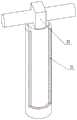
图1为本实用新型整体结构示意图。Figure 1 is a schematic diagram of the overall structure of the utility model.
图2为本实用新型阀体和储液箱、储水箱配合示意图。FIG. 2 is a schematic diagram of the cooperation of the valve body, the liquid storage tank and the water storage tank of the utility model.
图3为本实用新型第一进气管和储液箱配合示意图。FIG. 3 is a schematic diagram of the cooperation between the first air inlet pipe and the liquid storage tank of the present invention.
图4为本实用新型进气机构示意图。FIG. 4 is a schematic diagram of the air intake mechanism of the present invention.
图5为本实用新型搅拌扇和第四锥齿轮配合示意图。FIG. 5 is a schematic diagram of the cooperation between the stirring fan and the fourth bevel gear of the present invention.
图6为本实用新型外轴剖面示意图。FIG. 6 is a schematic cross-sectional view of the outer shaft of the utility model.
图7为本实用新型阀体剖面示意图。FIG. 7 is a schematic sectional view of the valve body of the present invention.
图8为本实用新型换向开关剖面示意图。8 is a schematic cross-sectional view of the reversing switch of the present invention.
图中标号:1-第一进气管、2-阀体、3-第二进气管、4-储水箱、5-储液箱、6-废液箱、7-软垫、8-连接盒、9-螺帽、10-出水管、11-箱体、12-出水单向阀、13-出液单向阀、14-出液管、15-喷淋头、16-波纹管、17-第一螺盖、18-第二螺盖、19-电机、20-第一带轮、21-皮带、22-第二带轮、23-第一锥齿轮、24-第二锥齿轮、25-圆柱凸轮、26-推杆、27-活塞、28-套筒、29-进气单向阀、30-出气管、31-第三锥齿轮、32-搅拌扇、33-内轴、34-第四锥齿轮、35-外轴、36-换向开关、37-第一圆孔、38-第二圆孔。Labels in the figure: 1-first intake pipe, 2-valve body, 3-second intake pipe, 4-water storage tank, 5-liquid storage tank, 6-waste liquid tank, 7-soft pad, 8-connection box, 9-nut, 10-outlet pipe, 11-box, 12-outlet check valve, 13-liquid check valve, 14-outlet pipe, 15-spray head, 16-bellows, 17-section A screw cap, 18-second screw cap, 19-motor, 20-first pulley, 21-belt, 22-second pulley, 23-first bevel gear, 24-second bevel gear, 25-cylinder Cam, 26-push rod, 27-piston, 28-sleeve, 29-inlet check valve, 30-outlet pipe, 31-third bevel gear, 32-stirring fan, 33-inner shaft, 34-fourth Bevel gear, 35-external shaft, 36-reversing switch, 37-first round hole, 38-second round hole.
具体实施方式Detailed ways
下面结合附图1-8对本实用新型的具体实施方式做进一步详细说明。The specific embodiments of the present utility model will be further described in detail below with reference to the accompanying drawings 1-8.
本实用新型包括箱体11,所述箱体11的上端固定连接有储水箱4和储液箱5,箱体11内设有出气机构,出气机构的左侧连接有阀体2,阀体2内设有可转动的换向开关36,阀体2的后端固定连接有第一进气管1,第一进气管1的上端固定连接于储液箱5的上部外表面,阀体2的前端固定连接有第二进气管3,第二进气管3的上端固定连接于储水箱4上部外表面,转动换向开关36形成储水箱4进气或者储液箱5进气的结构。The utility model includes a
阀体2内的换向开关36的下端为一个球体,在日常状况下球体下端的第一圆孔37和第二圆孔38分别和阀体2前端孔和阀体2的右端孔对齐,出气机构排出气体,气体通过阀体2,然后通过第一进气管1将气体输入进储液箱5内,顺时针转动换向开关36九十度实现第一圆孔37和第二圆孔38与阀体2的右端孔和阀体2后端孔对齐,此时气体可以通过第二进气管3向储水箱4内进行进气,从而将储水箱4和储液箱5内部的气压增大。The lower end of the
所述储液箱5内部底面固定连接有外轴35,外轴35的上端固定连接有第四锥齿轮34,外轴35内转动连接有内轴33,内轴33上端两侧均铰接有第三锥齿轮31,第三锥齿轮31外侧同轴固定连接有搅拌扇32,第三锥齿轮31和第四锥齿轮34互相啮合,内轴33转动形成两个搅拌扇32自转的同时绕外轴35做公转的结构。The inner bottom surface of the
内轴33转动的时候,两侧的第三锥齿轮31会在外轴35的第四锥齿轮34外齿的作用下开始转动,从而实现两个搅拌扇32的转动,同时还会绕着外轴35进行公转,从而对药液进行更加均匀的搅拌,防止发生沉淀。When the
所述储水箱4的前端下部固定连接有出水管10,出水管10的上端固定连接有出水单向阀12,所述储液箱5的前端下部固定连接有出液管14,出液管14的上端固定连接有出液单向阀13,出液单向阀13和出水单向阀12上端固定连接有连接盒8,连接盒8的上端固定连接有波纹管16,波纹管16的上端固定连接有喷淋头15。A
当储水箱4内部的气压升高后,会将水从储水箱4底部通过出水管10和出水单向阀12,然后通过连接盒8和波纹管16,从喷淋头15均匀喷出,波纹管16可以随意的变换角度和一定的长度,可以方便病人多角度多方位的对病灶进行冲洗,同理,当储液箱5内部的气压增大时,药液会通过出液管14、出液单向阀13、连接盒8、波纹管16和喷淋头15均匀喷出,并且出液单向阀13和出水单向阀12保证从储液箱5和储水箱4内排出的液体不会发生倒流。When the air pressure inside the water storage tank 4 rises, the water will pass through the
所述出气机构包括出气管30,出气管30的右侧固定连接有套筒28,套筒28的左端固定连接有进气单向阀29,套筒28内部滑动连接有活塞27,活塞27的右侧固定连接有推杆26,推杆26的右端上部配合有圆柱凸轮25,圆柱凸轮25的右侧同轴固接有第二锥齿轮24,第二锥齿轮24的上部啮合有第一锥齿轮23,第一锥齿轮23的上端同轴固接有第二带轮22,第二带轮22的外缘连接有皮带21,皮带21的右端连接有第一带轮20,第一带轮20的下方固定连接有电机19,电机19的下端固定连接于箱体11的下底面,电机19和上端的内轴33固定连接。The air outlet mechanism includes an
电机19转动带动上方的第一带轮20转动,第一带轮20通过皮带21带动第二带轮22转动,第二带轮22通过第一锥齿轮23和第二锥齿轮24实现圆柱凸轮25的转动,圆柱凸轮25表面开有滑槽,下方的推杆26上端固定连接有销杆,销杆可以在圆柱凸轮25的滑槽内来回滑动,圆柱凸轮25转动实现推杆26的左右水平移动,进而实现活塞27的水平移动,在进气单向阀29的配合下,实现电机19转动活塞27不断左右往复运动,从而实现出气管30不断的出气。The rotation of the
所述箱体11的后端固定连接有废液箱6,废液箱6的上端固定连接有软垫7,废液箱6的后端螺纹连接有螺帽9。A
在使用的时候病人可以坐在软垫7上,然后进行冲洗提升了舒适性,并且冲洗下来的废水可以直接流进废液箱6内,废液可以通过将废液箱6后端的螺帽9拧掉就可以将废液排出。During use, the patient can sit on the
所述储液箱5的上端螺纹连接有第一螺盖17,储水箱4的上端螺纹连接有第二螺盖18。The upper end of the
通过将第一螺盖17和第二螺盖18旋转掉,二实现分别向储液箱5内加药液和储水箱4内加水。By rotating off the
本实用新型使用时,病人可以坐在软垫7上,然后进行冲洗提升了舒适性,此时电机19转动带动上方的第一带轮20转动,第一带轮20通过皮带21带动第二带轮22转动,第二带轮22通过第一锥齿轮23和第二锥齿轮24实现圆柱凸轮25的转动,圆柱凸轮25表面开有滑槽,下方的推杆26上端固定连接有销杆,销杆可以在圆柱凸轮25的滑槽内来回滑动,圆柱凸轮25转动实现推杆26的左右水平移动,进而实现活塞27的水平移动,在进气单向阀29的配合下,实现电机19转动活塞27不断左右往复运动,从而实现出气管30不断的出气,此时气体到达阀体2,阀体2内的换向开关36的下端为一个球体,在日常状况下球体下端的第一圆孔37和第二圆孔38分别和阀体2前端孔和阀体2的右端孔对齐,出气机构排出气体,气体通过阀体2,然后通过第一进气管1将气体输入进储液箱5内,顺时针转动换向开关36九十度实现第一圆孔37和第二圆孔38与阀体2的右端孔和阀体2后端孔对齐,此时气体可以通过第二进气管3向储水箱4内进行进气,从而将储水箱4和储液箱5内部的气压增大,当储水箱4内部的气压升高后,会将水从储水箱4底部通过出水管10和出水单向阀12,然后通过连接盒8和波纹管16,从喷淋头15均匀喷出,波纹管16可以随意的变换角度和一定的长度,可以方便病人多角度多方位的对病灶进行冲洗,同理,当储液箱5内部的气压增大时,药液会通过出液管14、出液单向阀13、连接盒8、波纹管16和喷淋头15均匀喷出,并且出液单向阀13和出水单向阀12保证从储液箱5和储水箱4内排出的液体不会发生倒流,当病人进行药液清洗过后,可直接转动换向开关36来实现清水的冲洗,不用再另外去接清水进行冲洗,并且电机19转动的同时会带动上方的内轴33转动,内轴33转动的时候,两侧的第三锥齿轮31会在外轴35的第四锥齿轮34外齿的作用下开始转动,从而实现两个搅拌扇32的转动,同时还会绕着外轴35进行公转,从而对药液进行更加均匀的搅拌,防止发生沉淀,并且本装置的气密性很好,不会发生漏水漏气的现象帮助病人更好的进行冲洗治疗。When the utility model is in use, the patient can sit on the
本实用新型结构新颖,构思巧妙,操作简单方便,通过本设计有效的解决了常规泌尿外科护理用冲洗装置功能单一,冲洗过程中病人舒适性不高,并且药液会出现沉淀,以及废液不能收集的问题,提高了病人冲洗的舒适性和便捷性。The utility model has the advantages of novel structure, ingenious conception, simple and convenient operation, and effectively solves the problem that the conventional urological nursing irrigation device has a single function, the patient's comfort is not high during the rinsing process, the medicinal liquid will precipitate, and the waste liquid cannot be The problem of collection improves the comfort and convenience of patient flushing.
最后应说明的是:以上所述仅为本实用新型的优选实施例而已,并不用于限制本实用新型,尽管参照前述实施例对本实用新型进行了详细的说明,对于本领域的技术人员来说,其依然可以对前述各实施例所记载的技术方案进行修改,或者对其中部分技术特征进行等同替换,凡在本实用新型的精神和原则之内,所作的任何修改、等同替换、改进等,均应包含在本实用新型的保护范围之内。Finally, it should be noted that the above are only the preferred embodiments of the present invention, and are not intended to limit the present invention. , it can still modify the technical solutions recorded in the foregoing embodiments, or perform equivalent replacements to some of the technical features. Any modification, equivalent replacement, improvement, etc. made within the spirit and principle of the present utility model, All should be included within the protection scope of the present invention.
Claims (5)
Priority Applications (1)
| Application Number | Priority Date | Filing Date | Title |
|---|---|---|---|
| CN201922351980.0UCN211301453U (en) | 2019-12-24 | 2019-12-24 | Irrigation device for urological care |
Applications Claiming Priority (1)
| Application Number | Priority Date | Filing Date | Title |
|---|---|---|---|
| CN201922351980.0UCN211301453U (en) | 2019-12-24 | 2019-12-24 | Irrigation device for urological care |
Publications (1)
| Publication Number | Publication Date |
|---|---|
| CN211301453Utrue CN211301453U (en) | 2020-08-21 |
Family
ID=72061134
Family Applications (1)
| Application Number | Title | Priority Date | Filing Date |
|---|---|---|---|
| CN201922351980.0UExpired - Fee RelatedCN211301453U (en) | 2019-12-24 | 2019-12-24 | Irrigation device for urological care |
Country Status (1)
| Country | Link |
|---|---|
| CN (1) | CN211301453U (en) |
- 2019
- 2019-12-24CNCN201922351980.0Upatent/CN211301453U/ennot_activeExpired - Fee Related
Similar Documents
| Publication | Publication Date | Title |
|---|---|---|
| CN111939363A (en) | Portable cleaning and sterilizing device for gynecological nursing | |
| CN111467156A (en) | Urethra medicine feeding device for urology surgery | |
| CN117427235A (en) | Intestinal decompression flushing device | |
| CN211301453U (en) | Irrigation device for urological care | |
| CN110917434B (en) | Clinical nursing device for removing foreign bodies from patient wounds | |
| CN211382646U (en) | Vagina cleaner for gynecological nursing | |
| CN209422745U (en) | A kind of department of general surgery's wound disinfection equipment easy to use | |
| CN108187169B (en) | A kind of gynemetrics's washer easy to operate | |
| CN111359044A (en) | Urinary surgery nursing flushing device for flushing focus parts of patient | |
| CN207980098U (en) | Hospital bed of gynecopathy and flusher | |
| CN213191841U (en) | Disinfection flusher for skin | |
| CN210301875U (en) | Gynaecology uses multi-functional flusher | |
| CN113856017A (en) | Medicine sprayer for treatment of department of respiration | |
| CN221814902U (en) | Uropoiesis surgery flusher | |
| CN219148582U (en) | Vomit collecting device | |
| CN221950332U (en) | Portable visual ear irrigation suction device | |
| CN217697473U (en) | A surgical care irrigation device | |
| CN217567122U (en) | Medicine applicator for gynecological examination | |
| CN217286678U (en) | Gynecological cleaning nursing device | |
| CN215740602U (en) | A vomit collection device for nursing care in an oncology department | |
| CN111632209A (en) | An easy-to-use urological catheterization nursing device | |
| CN222765513U (en) | Flushing device for urinary surgery | |
| CN214129736U (en) | Wound cleaning device for orthopedics department | |
| CN210750563U (en) | Bladder flushing device capable of controlling water temperature and used for prostate postoperative patient | |
| CN215504772U (en) | A kind of nursing device for urology |
Legal Events
| Date | Code | Title | Description |
|---|---|---|---|
| GR01 | Patent grant | ||
| GR01 | Patent grant | ||
| CF01 | Termination of patent right due to non-payment of annual fee | ||
| CF01 | Termination of patent right due to non-payment of annual fee | Granted publication date:20200821 |