CN211231703U - A lever-type switching valve and a faucet - Google Patents
A lever-type switching valve and a faucetDownload PDFInfo
- Publication number
- CN211231703U CN211231703UCN201922116106.9UCN201922116106UCN211231703UCN 211231703 UCN211231703 UCN 211231703UCN 201922116106 UCN201922116106 UCN 201922116106UCN 211231703 UCN211231703 UCN 211231703U
- Authority
- CN
- China
- Prior art keywords
- valve
- cavity
- water outlet
- water
- hole
- Prior art date
- Legal status (The legal status is an assumption and is not a legal conclusion. Google has not performed a legal analysis and makes no representation as to the accuracy of the status listed.)
- Active
Links
Images


Landscapes
- Multiple-Way Valves (AREA)
Abstract
Translated fromChinese
Description
Translated fromChinese技术领域technical field
本实用新型涉及卫浴技术领域,具体而言,涉及一种拨杆式切换阀及水龙头。The utility model relates to the technical field of sanitary ware, in particular to a lever type switching valve and a water faucet.
背景技术Background technique
切换阀被广泛应用于多种卫浴产品,是卫浴产品的重要组成元件,用以实现不同出水口的切换,例如淋浴水龙头的切换阀需要将出水方向切换为花洒出口、手持花洒出口、下出水口及其它出水口。切换阀的设计严重影响卫浴产品的使用体验。Switching valves are widely used in a variety of bathroom products and are an important component of bathroom products. They are used to switch between different water outlets. For example, the switching valve of a shower faucet needs to switch the water outlet direction to shower outlet, hand shower outlet, and down. Water outlet and other water outlets. The design of the switching valve seriously affects the experience of bathroom products.
目前,切换阀主要为旋转式切换阀,该切换阀存在的缺点为指向不清晰、操作较为麻烦,特别是在多功能出水的时候,如果要切换至非相邻的出水口,则必须经过两者之间的出水口,体验感较差。At present, the switching valve is mainly a rotary switching valve. The disadvantages of this switching valve are that the direction is not clear and the operation is more troublesome. Especially when the multi-function water outlet is used, if you want to switch to a non-adjacent water outlet, you must go through two The water outlet between the users has a poor experience.
实用新型内容Utility model content
本实用新型提供了一种拨杆式切换阀,旨在改善切换阀在切换出水口时指向不清晰的问题。The utility model provides a lever type switching valve, which aims to improve the problem that the switching valve does not point clearly when switching the water outlet.
本实用新型还提供了包含拨杆式切换阀的水龙头,旨在改善水龙头切换出水口时指向不清楚的问题。The utility model also provides a faucet including a lever-type switching valve, which aims to improve the problem of unclear direction when the faucet switches the water outlet.
本实用新型是这样实现的:The utility model is realized in this way:
一种拨杆式切换阀,包括:阀盖、阀体和拨杆件,A lever type switching valve, comprising: a valve cover, a valve body and a lever element,
所述阀体具有一凹腔,所述凹腔的腔壁上设有进水口以及周设于所述进水口的多个彼此分隔的出水口,流体从所述进水口流入;The valve body has a concave cavity, the cavity wall of the concave cavity is provided with a water inlet and a plurality of mutually separated water outlets arranged around the water inlet, and the fluid flows in from the water inlet;
所述阀盖盖合于所述阀体上,所述阀盖的内腔与所述凹腔构造成球形阀室;The valve cover is covered on the valve body, and the inner cavity of the valve cover and the concave cavity are configured to form a spherical valve chamber;
所述拨杆件包括安装在所述阀室内的球体以及驱动所述球体旋转的阀杆,所述球体具有一容腔,所述容腔的腔壁上开设与所述进水口位置对应的通水孔和与所述出水口位置一一对应的多个分流孔,所述阀杆伸出所述阀盖,且可转动以使所述球体在关闭位置和多个开启位置之间进行调节,且始终保持所述通水孔与所述进水口的连通状态;The lever member includes a sphere installed in the valve chamber and a valve stem that drives the sphere to rotate, the sphere has a cavity, and a channel corresponding to the position of the water inlet is provided on the cavity wall of the cavity. a water hole and a plurality of shunt holes corresponding to the positions of the water outlet, the valve stem extends out of the valve cover, and can be rotated so that the ball can be adjusted between a closed position and a plurality of open positions, And always keep the communication state between the water hole and the water inlet;
在所述关闭位置,所述阀杆未拨动,每个所述分流孔均和与之对应的所述出水口错开,在所述开启位置,对应所述阀杆拨动方向上的所述分流孔和与之对应的所述出水口连通。In the closed position, the valve stem is not toggled, and each of the diverting holes is staggered from the corresponding water outlet. In the open position, corresponding to the valve stem in the toggle direction The shunt hole communicates with the corresponding water outlet.
进一步地,在本实用新型较佳的实施例中,所述阀体和所述球体的接触面设有密封垫,所述密封垫具有与所述凹腔的腔壁贴合的腔密封部,所述腔密封部与所述进水口和所述出水口对应的位置均设有形状相适的开孔。Further, in a preferred embodiment of the present utility model, the contact surface of the valve body and the sphere is provided with a sealing gasket, and the sealing gasket has a cavity sealing portion that fits with the cavity wall of the cavity, The cavity sealing portion is provided with openings with appropriate shapes at positions corresponding to the water inlet and the water outlet.
进一步地,在本实用新型较佳的实施例中,所述密封垫还包括沿所述开孔的周缘向所述凹腔方向延伸的多个孔密封部,多个所述孔密封部分别插入与之位置对应的所述进水口、所述出水口。Further, in a preferred embodiment of the present invention, the gasket further includes a plurality of hole sealing parts extending along the periphery of the opening toward the cavity, and the plurality of hole sealing parts are respectively inserted into The water inlet and the water outlet corresponding to their positions.
进一步地,在本实用新型较佳的实施例中,所述进水口靠近所述凹腔的端口为圆形孔,所述出水口靠近所述凹腔的端口为腰形孔。Further, in a preferred embodiment of the present invention, the port of the water inlet close to the cavity is a circular hole, and the port of the water outlet close to the cavity is a waist-shaped hole.
进一步地,在本实用新型较佳的实施例中,所述球体为不锈钢球材质。Further, in a preferred embodiment of the present invention, the sphere is made of stainless steel.
进一步地,在本实用新型较佳的实施例中,所述阀体的底部设有密封圈。Further, in a preferred embodiment of the present invention, the bottom of the valve body is provided with a sealing ring.
进一步地,在本实用新型较佳的实施例中,所述分流孔开设在与之对应的所述出水口的转动上方位置,所述阀杆转动,驱动该转动方向上的所述分流孔下移,以使该转动方向上对应的所述出水口被打开。Further, in a preferred embodiment of the present invention, the shunt hole is opened at a position above the rotation of the water outlet corresponding to it, and the valve stem rotates to drive the lower part of the shunt hole in the direction of rotation. move, so that the water outlet corresponding to the rotation direction is opened.
进一步地,在本实用新型较佳的实施例中,每个所述出水口均包括连通外部的出水段以及连通所述凹腔和所述出水段的过渡段,所述过渡段倾斜设置。Further, in a preferred embodiment of the present invention, each of the water outlets includes a water outlet section that communicates with the outside and a transition section that communicates with the cavity and the water outlet section, and the transition sections are arranged obliquely.
进一步地,在本实用新型较佳的实施例中,所述阀盖和所述阀体卡接固定。Further, in a preferred embodiment of the present invention, the valve cover and the valve body are clamped and fixed.
一种水龙头,包含权上述的拨杆式切换阀。A faucet includes the above-mentioned lever-type switching valve.
本实用新型的有益效果是:The beneficial effects of the present utility model are:
本实用新型通过上述设计得到的拨杆式切换阀,操作简便,指向清晰。使用时,拨杆件未拨动状态下(即阀杆保持直立状态时),出水关闭。通过阀杆的拨动,对应拨动方向上的分流口和与之对应的出水口连通,从进水口进入的流体通过通水孔进入到球体的腔室内,然后再通过分流孔进入到与该分流孔位置对应的出水口,实现对应拨动方向上的出水口出水,更加符合人体工学和使用者的操作习惯,产品体验感好。且在不同出水口的切换过程中,不需要在经过其他出水口,避免其他出水口出水。The lever type switching valve obtained by the above-mentioned design of the utility model has the advantages of simple operation and clear pointing. When in use, when the lever is not moved (that is, when the valve stem is kept upright), the water outlet is closed. Through the toggle of the valve stem, the shunt port in the corresponding toggle direction is connected with the corresponding water outlet, and the fluid entering from the water inlet enters the chamber of the sphere through the water hole, and then enters through the shunt hole. The water outlet corresponding to the position of the diverter hole realizes the water outlet in the corresponding toggle direction, which is more in line with ergonomics and the user's operating habits, and the product experience is good. And in the process of switching between different water outlets, there is no need to pass through other water outlets to avoid water from other water outlets.
附图说明Description of drawings
为了更清楚地说明本实用新型实施方式的技术方案,下面将对实施方式中所需要使用的附图作简单地介绍,应当理解,以下附图仅示出了本实用新型的某些实施例,因此不应被看作是对范围的限定,对于本领域普通技术人员来讲,在不付出创造性劳动的前提下,还可以根据这些附图获得其他相关的附图。In order to illustrate the technical solutions of the embodiments of the present invention more clearly, the accompanying drawings required in the embodiments will be briefly introduced below. It should be understood that the following drawings only show some embodiments of the present invention. Therefore, it should not be regarded as a limitation of the scope. For those of ordinary skill in the art, other related drawings can also be obtained from these drawings without any creative effort.
图1是本实用新型实施例1的拨杆式切换阀的结构示意图;Fig. 1 is the structural representation of the lever type switching valve of Embodiment 1 of the present utility model;
图2是图1所示的拨杆式切换阀的分解结构示意图;Fig. 2 is the exploded structure schematic diagram of the lever type switching valve shown in Fig. 1;
图3是图1所示的阀盖的结构示意图;Fig. 3 is the structural schematic diagram of the valve cover shown in Fig. 1;
图4是图1所示的拨杆件的结构示意图;Fig. 4 is the structural representation of the lever member shown in Fig. 1;
图5是图1所示的密封垫的结构示意图;Fig. 5 is the structural representation of the gasket shown in Fig. 1;
图6是图1所示的阀体的结构示意图;Figure 6 is a schematic structural diagram of the valve body shown in Figure 1;
图7是图6所示的阀体的剖切结构示意图;FIG. 7 is a schematic cross-sectional view of the valve body shown in FIG. 6;
图8是图1所示的拨杆式切换阀左边出水的结构示意图;Fig. 8 is the structural schematic diagram of the water outlet on the left side of the lever type switching valve shown in Fig. 1;
图9是图1所示的拨杆式切换阀右边出水的结构示意图。FIG. 9 is a schematic structural diagram of the water outlet on the right side of the lever type switching valve shown in FIG. 1 .
图标:100-拨杆式切换阀;10-阀体;101-凹腔;11-进水口;12-出水口;121-出水段;122-过渡段;13-插槽;14-卡块;15-垫片槽;20-阀盖;201-内腔;202-转动空间;21-耳部;22-卡孔;30-拨杆件;301-容腔;31-阀杆;32-球体;321-通水孔;322-分流孔;40-密封垫;401-开孔;41-腔密封部;42-孔密封部;50-密封圈。Icon: 100-lever switch valve; 10-valve body; 101-cavity; 11-water inlet; 12-water outlet; 121-water outlet; 122-transition; 13-slot; 14-block; 15-gasket groove; 20-bonnet; 201-inner cavity; 202-rotation space; 21-ear part; 22-card hole; 30-lever part; 301-cavity; 31-valve stem; ; 321 - water hole; 322 - shunt hole; 40 - gasket; 401 - opening; 41 - cavity sealing part; 42 - hole sealing part; 50 - sealing ring.
具体实施方式Detailed ways
为使本实用新型实施方式的目的、技术方案和优点更加清楚,下面将结合本实用新型实施方式中的附图,对本实用新型实施方式中的技术方案进行清楚、完整地描述,显然,所描述的实施方式是本实用新型一部分实施方式,而不是全部的实施方式。基于本实用新型中的实施方式,本领域普通技术人员在没有作出创造性劳动前提下所获得的所有其他实施方式,都属于本实用新型保护的范围。因此,以下对在附图中提供的本实用新型的实施方式的详细描述并非旨在限制要求保护的本实用新型的范围,而是仅仅表示本实用新型的选定实施方式。基于本实用新型中的实施方式,本领域普通技术人员在没有作出创造性劳动前提下所获得的所有其他实施方式,都属于本实用新型保护的范围。In order to make the purposes, technical solutions and advantages of the embodiments of the present invention more clear, the technical solutions in the embodiments of the present invention will be clearly and completely described below with reference to the accompanying drawings in the embodiments of the present invention. Obviously, the described The embodiments of the present invention are a part of the embodiments of the present invention, but not all of the embodiments. Based on the embodiments of the present invention, all other embodiments obtained by those of ordinary skill in the art without creative work fall within the protection scope of the present invention. Accordingly, the following detailed description of the embodiments of the invention provided in the accompanying drawings is not intended to limit the scope of the invention as claimed, but is merely representative of selected embodiments of the invention. Based on the embodiments of the present invention, all other embodiments obtained by those of ordinary skill in the art without creative work fall within the protection scope of the present invention.
在本实用新型的描述中,需要理解的是,术语“中心”、“纵向”、“横向”、“长度”、“宽度”、“厚度”、“上”、“下”、“前”、“后”、“左”、“右”、“竖直”、“水平”、“顶”、“底”、“内”、“外”、“顺时针”、“逆时针”等指示的方位或位置关系为基于附图所示的方位或位置关系,仅是为了便于描述本实用新型和简化描述,而不是指示或暗示所指的设备或元件必须具有特定的方位、以特定的方位构造和操作,因此不能理解为对本实用新型的限制。In the description of the present invention, it should be understood that the terms "center", "longitudinal", "lateral", "length", "width", "thickness", "upper", "lower", "front", "Back", "Left", "Right", "Vertical", "Horizontal", "Top", "Bottom", "Inner", "Outer", "Clockwise", "Counterclockwise" etc. Or the positional relationship is based on the orientation or positional relationship shown in the accompanying drawings, which is only for the convenience of describing the present invention and simplifying the description, rather than indicating or implying that the referred device or element must have a specific orientation, be constructed in a specific orientation and operation, so it cannot be construed as a limitation to the present invention.
此外,术语“第一”、“第二”仅用于描述目的,而不能理解为指示或暗示相对重要性或者隐含指明所指示的技术特征的数量。由此,限定有“第一”、“第二”的特征可以明示或者隐含地包括一个或者更多个该特征。在本实用新型的描述中,“多个”的含义是两个或两个以上,除非另有明确具体的限定。In addition, the terms "first" and "second" are only used for descriptive purposes, and should not be construed as indicating or implying relative importance or implying the number of indicated technical features. Thus, a feature defined as "first" or "second" may expressly or implicitly include one or more of that feature. In the description of the present invention, "plurality" means two or more, unless otherwise expressly and specifically defined.
在本实用新型中,除非另有明确的规定和限定,术语“安装”、“相连”、“连接”、“固定”等术语应做广义理解,例如,可以是固定连接,也可以是可拆卸连接,或成一体;可以是机械连接,也可以是电连接;可以是直接相连,也可以通过中间媒介间接相连,可以是两个元件内部的连通或两个元件的相互作用关系。对于本领域的普通技术人员而言,可以根据具体情况理解上述术语在本实用新型中的具体含义。In the present utility model, unless otherwise expressly specified and limited, the terms "installation", "connection", "connection", "fixed" and other terms should be understood in a broad sense, for example, it may be a fixed connection or a detachable connection Connection, or integration; it can be a mechanical connection or an electrical connection; it can be a direct connection or an indirect connection through an intermediate medium, and it can be the internal communication between the two elements or the interaction relationship between the two elements. For those of ordinary skill in the art, the specific meanings of the above terms in the present invention can be understood according to specific situations.
在本实用新型中,除非另有明确的规定和限定,第一特征在第二特征之“上”或之“下”可以包括第一和第二特征直接接触,也可以包括第一和第二特征不是直接接触而是通过它们之间的另外的特征接触。而且,第一特征在第二特征“之上”、“上方”和“上面”包括第一特征在第二特征正上方和斜上方,或仅仅表示第一特征水平高度高于第二特征。第一特征在第二特征“之下”、“下方”和“下面”包括第一特征在第二特征正下方和斜下方,或仅仅表示第一特征水平高度小于第二特征。In the present invention, unless otherwise expressly specified and limited, a first feature "on" or "under" a second feature may include the first and second features in direct contact, or may include the first and second features The features are not in direct contact but through additional features between them. Also, the first feature being "above", "over" and "above" the second feature includes the first feature being directly above and obliquely above the second feature, or simply means that the first feature is level higher than the second feature. The first feature is "below", "below" and "below" the second feature includes the first feature being directly below and diagonally below the second feature, or simply means that the first feature has a lower level than the second feature.
实施例1Example 1
为了便于描述,以下用水指代流体。但本领域技术人员应知,本实用新型的流体可以是任何合适的流体。For ease of description, water is used below to refer to the fluid. However, those skilled in the art should know that the fluid of the present invention can be any suitable fluid.
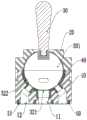
参照图1所示,本实施例提供一种拨杆式切换阀100,包括阀体10、阀盖20和拨杆件30。Referring to FIG. 1 , this embodiment provides a lever-type switching valve 100 , which includes a
请参阅图2,阀体10大致呈圆柱体,阀体的上端部具有一向内凹陷的凹腔101。凹腔101的腔壁上设有进水口11以及周设于进水口11的多个彼此分隔的出水口12,进水口11与外部管路连通,外部管路的水流从进水口11进入,并随拨杆件30切换从不同的出水口12流出,实现不同出水位置的切换。Referring to FIG. 2 , the
进一步优选地,进水口11设置在阀体10的中部,进水口11的周侧设有4个出水口12,4个出水口12均匀分布在进水口11的上、下、左、右四个方向上。在一个使用场景中,上侧的出水口12连通顶部花洒,下侧的出水口12连通淋浴水龙头的下出水口,右侧的出水口12连通手持花洒,左侧的出水口12连通其他出水装置。Further preferably, the
需要说明的是,在其他实施例中,进水口11的周侧也可以设置两个出水口12或3个、5个、6个乃至更多的出水口12。设计者可以根据实际使用需求调整即可。保证出水口12围绕进水口11排布,以使得在多个出水口12进行切换时,不需要经过其他出水口。It should be noted that, in other embodiments, two
阀盖20盖合于阀体10上,与阀体10固定。优选地,本实施例中,阀盖20和阀体10卡接固定,便于实现拆装。具体地,阀体10的相对两侧的外壁上开设有可供向下插入的插槽13,插槽13内设有卡块14。The
对应的,阀盖20的相对两侧设有与插槽13适配的耳部21,耳部21上设有卡孔22,卡孔22插入插槽13中,通过卡块14和卡孔22实现阀盖20和阀体10的卡接固定。Correspondingly, the opposite sides of the
请参阅图2和图3,阀盖20的内腔201与凹腔101构造成球形阀室,且阀盖20顶端具有一供阀杆转动的转动空间202,转动空间202呈倒锥台状,以保证阀杆具有一定的转动自由度。Please refer to FIGS. 2 and 3 , the
进一步地,在较佳的实施例中,凹腔101大致呈半球状,阀盖20的内腔201也大致呈半球状,二者构造出球形阀室。Further, in a preferred embodiment, the
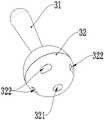
请参阅图2和图4,拨杆件30包括安装在球形阀室内的球体32以及驱动球体32旋转的阀杆31。球体32被限定在阀盖20和阀体10构造出的球形阀室中,球体31的外周面与球形阀室的内壁贴合,且球体32随阀杆31的拨动动作发生转动。Referring to FIGS. 2 and 4 , the
进一步地,在较佳的实施例中,转动空间202限定阀杆31的最大转动角度为20~40°,避免阀杆31过度转动,结构更紧凑。需要说明的是,本实施例所指的最大转动角度为阀杆31未拨动状态(即直立状态下)至向某一方向拨动至触碰转动空间202边缘处的位置。Further, in a preferred embodiment, the
进一步优选地,阀杆31与球体32通过螺纹连接实现固定。Further preferably, the
球体32具有一容腔301,容腔301的腔壁上开设与进水口11位置对应的通水孔321和与出水口12位置一一对应的多个分流孔322。阀杆31伸出阀盖20,且可转动以使球体32在关闭位置和多个开启位置之间进行调节,且始终保持通水孔321与进水口11的连通状态。在关闭位置,阀杆31未拨动,每个分流孔322均和与之对应的出水口12位置错开,在开启位置,对应阀杆31拨动方向上的分流孔322和与之对应的出水口12连通。The
优选地,本实施例中,球体32为空心球体,对应每个出水口12,容腔301的腔壁上设有对应的分流孔322。从进水口11流出的水通过通水孔321进入到容腔301中,然后再经分流孔322进入到与之对应的出水口12中。Preferably, in this embodiment, the
具体地,本实施例中,球体32与阀杆31位置相对的底端设有通水孔321,通水孔321四周均匀分布有4个与出水口12一一对应的分流孔322。Specifically, in this embodiment, the bottom end of the
需要说明的是,在其他实施例中,球体32也可以不是空心球体,例如可以半空心结构,只要满足具有容腔即可。It should be noted that, in other embodiments, the
进一步地,在较佳的实施例中,分流孔322开设在与之对应的出水口12的转动上方位置。即阀杆31直立状态下,分流孔322处于出水口12的上方位置。阀杆31转动,驱动该转动方向上的分流孔322下移,分流孔322和出水口12的位置正对,以使该转动方向上对应的出水口12被打开。Further, in a preferred embodiment, the diverting
在本实施例中,定义进水口11和出水口12之间的弧长为A,定义出水口靠近凹腔101的端口的弧长为B,定义通水孔321和分流孔322之间的弧长为C,则A+B<C,以保证能够关闭出水口12。In this embodiment, the arc length between the
请参阅图5,进一步地,在较佳的实施例中,阀体10和球体32的接触面设有密封垫40。密封垫40大致呈碗状结构,具有与凹腔101的腔壁贴合的腔密封部41,腔密封部41与进水口11和出水口12对应的位置均设有形状相适的开孔401。腔密封部41能够使得阀体10和球体32良好密封。Referring to FIG. 5 , further, in a preferred embodiment, the contact surface of the
进一步地,在较佳的实施例中,密封垫40还包括沿开孔401的周缘向凹腔101方向延伸的多个孔密封部42,多个孔密封部42插入与之位置对应的进水口11、出水口12。通过设置插入到进水口11、出水口12的孔密封部42,进一步保证阀体10和球体32的密封效果。Further, in a preferred embodiment, the
进一步地,在较佳的实施例中,阀体10的底部设有密封圈50。密封圈50的形状与进水口11、出水口12底部端口相适配。在阀体10的下端面上,均沿距离进水口11和出水口12边缘预设距离处内凹形成垫片槽15。预设距离例如可以是0.05~3cm,但不局限于此。密封圈50与垫片槽15相适配,且密封圈50的高度略高于垫片槽15的深度。通过密封垫40和密封圈50实现对进水口11和每个出水口12的密封,密封效果好。Further, in a preferred embodiment, the bottom of the
可以理解的是,密封垫40和密封圈50的材质例如可以是橡胶等。It can be understood that, the material of the sealing
进一步地,在较佳的实施例中,进水口11靠近凹腔101的端口为圆形孔,出水口12靠近凹腔101的端口为腰形孔。Further, in a preferred embodiment, the port of the
请参阅图6和图7,进一步地,在较佳的实施例中,每个出水口12均包括连通外部的出水段121以及连通凹腔101和出水段121的过渡段122,过渡段122倾斜设置。通过该设置,使得结构更为紧凑,且出水口12与不同出水装置的适配性更佳。Please refer to FIG. 6 and FIG. 7 , further, in a preferred embodiment, each
进一步地,在较佳的实施例中,球体32为不锈钢球材质。球体32为不锈钢球,转动的阻尼小、耐磨、耐腐蚀性能好。Further, in a preferred embodiment, the
本实施例还提供一种水龙头,包含上述的拨杆式切换阀100。水龙头的具体构造本领域技术人员可以根据自己的需求选用,在此不再进行赘述。This embodiment also provides a faucet, which includes the above-mentioned lever-type switching valve 100 . The specific structure of the faucet can be selected by those skilled in the art according to their own needs, which will not be repeated here.
综上,本实施例提供的拨杆式切换阀100的工作原理如下:To sum up, the working principle of the lever-type switching valve 100 provided in this embodiment is as follows:
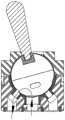
如图1所示,阀杆31保持直立状态时,为未拨动状态,该位置下,通水孔321保持和进水口11的连通状态,但各分流孔322均和与之对应的出水口12位置错开,各出水口12均不出水。As shown in FIG. 1 , when the
如图8所示,阀杆31向左侧拨动,球体32顺时针转动,使得左侧的分流孔322下移至打开左侧的出水口12,实现左侧的出水口12出水。As shown in FIG. 8 , the
如图9所示,阀杆31向右侧拨动,球体32逆时针转动,使得右侧的分流孔322下移至打开右侧的出水口12,实现右侧的出水口12出水。As shown in FIG. 9 , the
以上所述仅为本实用新型的优选实施方式而已,并不用于限制本实用新型,对于本领域的技术人员来说,本实用新型可以有各种更改和变化。凡在本实用新型的精神和原则之内,所作的任何修改、等同替换、改进等,均应包含在本实用新型的保护范围之内。The above descriptions are only preferred embodiments of the present invention, and are not intended to limit the present invention. For those skilled in the art, the present invention may have various modifications and changes. Any modification, equivalent replacement, improvement, etc. made within the spirit and principle of the present invention shall be included in the protection scope of the present invention.
Claims (10)
Translated fromChinesePriority Applications (1)
| Application Number | Priority Date | Filing Date | Title |
|---|---|---|---|
| CN201922116106.9UCN211231703U (en) | 2019-11-29 | 2019-11-29 | A lever-type switching valve and a faucet |
Applications Claiming Priority (1)
| Application Number | Priority Date | Filing Date | Title |
|---|---|---|---|
| CN201922116106.9UCN211231703U (en) | 2019-11-29 | 2019-11-29 | A lever-type switching valve and a faucet |
Publications (1)
| Publication Number | Publication Date |
|---|---|
| CN211231703Utrue CN211231703U (en) | 2020-08-11 |
Family
ID=71921208
Family Applications (1)
| Application Number | Title | Priority Date | Filing Date |
|---|---|---|---|
| CN201922116106.9UActiveCN211231703U (en) | 2019-11-29 | 2019-11-29 | A lever-type switching valve and a faucet |
Country Status (1)
| Country | Link |
|---|---|
| CN (1) | CN211231703U (en) |
Cited By (1)
| Publication number | Priority date | Publication date | Assignee | Title |
|---|---|---|---|---|
| CN110953379A (en)* | 2019-11-29 | 2020-04-03 | 路达(厦门)工业有限公司 | Deflector rod type switching valve and faucet |
- 2019
- 2019-11-29CNCN201922116106.9Upatent/CN211231703U/enactiveActive
Cited By (1)
| Publication number | Priority date | Publication date | Assignee | Title |
|---|---|---|---|---|
| CN110953379A (en)* | 2019-11-29 | 2020-04-03 | 路达(厦门)工业有限公司 | Deflector rod type switching valve and faucet |
Similar Documents
| Publication | Publication Date | Title |
|---|---|---|
| US4378029A (en) | Single control faucet | |
| CN109595360B (en) | Water channel switching device and water outlet device | |
| CN201040267Y (en) | Shower multifunctional water outlet structure | |
| US10730060B2 (en) | Convenient switching valve | |
| CN216812983U (en) | Valve body, waste water valve and water purification equipment | |
| CN211231703U (en) | A lever-type switching valve and a faucet | |
| CN110529634A (en) | Shower body and shower equipment | |
| CN110953379A (en) | Deflector rod type switching valve and faucet | |
| CN111059323A (en) | A lever-type switching valve and a faucet | |
| CN211231700U (en) | Deflector rod type switching valve and faucet | |
| CN108150679B (en) | Integrated valve core and shower valve | |
| CN216975870U (en) | Water diversion and outflow device | |
| CN217559092U (en) | Double-confluence outlet valve body and concealed combined valve body | |
| JP4976664B2 (en) | Mixer tap | |
| CN207299495U (en) | Blowdown valve and there is its water heater | |
| US11300218B2 (en) | Three-way flow dividing valve structure | |
| CN210013282U (en) | Constant temperature shower faucet | |
| CN215563045U (en) | Bubbler capable of adjusting flow | |
| CN220177201U (en) | Water outlet device and switching mechanism thereof | |
| CN220836144U (en) | Side water outlet switching structure | |
| CN114738518B (en) | Valve group and kitchen and toilet appliance | |
| CN210095577U (en) | Shower bath | |
| CN213899984U (en) | Water tap with multiple water outlets | |
| JP2959012B2 (en) | Switching valve | |
| CN215214866U (en) | A kind of adapter faucet and faucet |
Legal Events
| Date | Code | Title | Description |
|---|---|---|---|
| GR01 | Patent grant | ||
| GR01 | Patent grant |